
FEM Modelling Approaches of Bolt Connections for the Dynamic Analyses of an Automotive Engine


1
Department of Industrial Engineering, University of Salerno, 84084 Fisciano, SA, Italy
2
Department of Chemical, Materials and Production Engineering, University of Naples Federico II, 80125 Naples, NA, Italy
*
Author to whom correspondence should be addressed.
Appl. Sci. 2021, 11(10), 4343; https://doi.org/10.3390/app11104343
Submission received: 12 April 2021
/
Revised: 6 May 2021
/
Accepted: 8 May 2021
/
Published: 11 May 2021
(This article belongs to the Special Issue Advances in Vibroacoustics and Aeroacustics of Marine, Aerospace and Automotive Systems)
Abstract
:Three different finite element method (FEM) modelling approaches of bolt connections of a four-stroke, four-cylinder petrol engine are presented, and the related results compared in terms of preprocessing time and accuracy. A full 3D modelling of the bolt connections was preliminarily validated through a comparison with experimental test data available for the whole engine. Two further modelling approaches, a 1D approach and a contact-based (0D) approach, were benchmarked considering their influence on the accuracy for the dynamic analysis of an engine. Each of the three approaches presented pros and cons, even if the 1D modelling could be envisaged as the recommended one in most of cases.
1. Introduction
Since early years of numerical computation, several methods have been developed to improve the efficiency of numerical simulation and to circumvent the limitations of power computing. In recent years, computer aided engineering (CAE) simulation has become a key tool in the designing process that allows to tackle complex problem concerning acoustics [1] and vibroacoustics/aeroacoustics [2] in several environments, e.g., automotive [3] and aerospace [4,5].
These advances in numerical methods proved beneficial, e.g., in the simulation of dynamic systems, which can require the solution of the equations of motion over large time intervals and with numerous time steps. Accurately assessing the dynamic behavior of these systems, when low–medium frequency vibrations are involved, often requires the use of multibody simulation and finite element method (FEM) [6].
Assembling the individual sub-components to build up global FEM models of structures can result in very large models, having a number of Degrees of Freedom (DoFs) which can easily exceed the limits of computer capacity, at least for reasonable runtimes. The question arises whether such FEM models can be reduced in size, e.g., through substructuring approaches [7], preserving at the same time the capability to represent the dynamic characteristics of structures with satisfactory accuracy. Moreover, the joint usage of different numerical approaches, like FEM-BEM (boundary element method), can prove beneficial for vibroacoustic assessment [8].
Linear dynamic finite element analysis can be considered very reliable today for the design of components in an automotive engine. Unfortunately, when these individual components are built into assemblies, the level of confidence in the results is reduced since the joints in the real structure introduce nonlinearities that cannot be reproduced with a linear model. In particular, the FEM analysis of individual components of automotive engine blocks provides high accuracy and a good agreement with the measured response data. However, when these components are assembled, the accuracy of such predictions can significantly deteriorate since models describing stiffness and friction properties of joints are linearised.
The dynamic response of crucial components often depends upon the dynamic behavior of bolted connections. As is usually the case, the accurate modeling of structures with many mechanical joints remains a challenging work as the nonlinear behavior included in assembled structures strongly depends on the interface properties. Joints have historically consisted of assemblies involving nuts, bolts, screws, etc. and the design and analysis of these joints can be quite challenging. A fully nonlinear analysis is required to include the influence of the bolted joints, model the flexibility in the contact interface, and consider the nonlinear behavior of the contact due to partial slip and separations.
Motivated by the current demands in high-performance structural analysis, and by a need to better model systems with localized nonlinearities, analysts have developed a number of different approaches for modeling and simulating the dynamics of a bolted-joint structure. However, it is still unclear which approach might be most effective for a given system or set of conditions.
An investigation based on tests and FEM simulations of a double channel beam-to-column connection was presented in [9]. Bolt components were represented in three-dimensional forms and boundary conditions between bolts, double channels and the column section were modeled with contact elements. A comparison between a complex nonlinear modelling for bolts and a more traditional rigid or linear-elastic flange joint was carried out in [10]. It was demonstrated that the nonlinear nature of a casing flange joint was needed for a detailed modelling of the contact interaction of joints. Along the same line, further researches were developed to enable FEM representation of bolts both accurate and computationally efficient. Particularly, one work compared a time-domain modelling of a whole joint and a frequency-domain node-to-node approach [11], whereas another compared multiple approaches (from detailed models to more simplified ones) to represent the behavior of single solid bolts under static and dynamic tension loading [12]. Bolt modelling approaches were also compared in [13], where a simplified modelling through 2D plates and bar elements (representing the bolts) and a fully non-linear 3D modelling were presented. The effects of element mesh refinements on the nut and bolt contact surfaces, and types of contacts were analyzed and discussed. In [14], an improved modeling approach was developed that led to a good correlation with the experimental results and a good understanding of the underlying nonlinear mechanisms at the flange interface.
The work in [15] investigated and compared four kinds of FEM modelling: a solid bolt model, a coupled bolt model, a spider bolt model and a no-bolt model. All the proposed models took into account of pretension effects and contacts between flanges to join and, among all these models. The solid bolt model (a 3D bolt with contact elements between head/nut and the flange interfaces) provided the most accurate responses compared with the experimental results. However, joining components through 3D models of bolts can be very expensive from the computational standpoint, especially for large structures, thus the coupled bolt model (a coupling between dofs of head/nut and flange), was reported as the best compromise between effectiveness and usefulness on accuracy and runtimes. For the sake of clarity, it is worth reporting that the case study was based on a large marine diesel engine, consisting of several parts connected by long stay bolts.
Analytical models of bolted joint structures undergoing transient excitation were presented in [16]. A FEM based structural modelling of composite bolted joints was described in [17,18]. In [19], four kinds of FEM bolt models were suggested for a structure with a bolted joint and, through a comparison with simple static experiment and modal test results, the effectiveness and usefulness of the bolt models were confirmed. Based on the Levenberg–Marquardt optimization algorithms, a more accurate calculation model of bolt head connection stiffness is proposed in [20], providing a universal assessment model for calculating the bolt head connection stiffness of various parameters.
Similar to [15], the focus of this work is related to the industrial issue of modelling complex and large structures from the dynamic standpoint, with particular reference to an internal combustion engine (ICE) for the automotive industry. However, the presented investigation can be straightforwardly extended to further engineering areas. ICE dynamics are explored especially in the low frequency range and at low engine speeds, where the direct vibration transmission at the engine mounts represents a critical excitation mechanism [21].
Within this framework, this work presents three approaches for the modelling of bolts interconnecting the mechanical components of an ICE, already used in [7]. The ICE under analysis is a four-cylinder, four-stroke, with 1200 cc engine displacement and manual transmission, originally modelled with all its sub-components, i.e., exhaust system, brackets, mounts, alternator, intake manifold, etc. It is worth noting that such ICE model comprised more than 100 sub-components, all of them interconnected by means of several bolts with different sizes, tightening torques, pretension loads, etc. Therefore, the proper modelling of such connections not only has to be as accurate as possible, but also computationally affordable, of general validity and not prone to user error implementation.
The rest of this paper is structured as it follows.
Firstly, a description of the FEM model of the ICE is provided, highlighting the model simplifications (some components were discarded) adopted to speed up the analyses.
Secondly, the three proposed modelling approaches of bolt connections are described. The engine dynamic results considering a full 3D modeling of bolts were compared with corresponding experimental outcomes for validation of this complex approach. Once validated, it was considered as a reference numerical model for benchmarking two simplified modelling approaches of bolt connections, namely a 1D simplified approach and a contact-based (0D) approach. The benchmark was based on frequency response function (FRF) analyses performed for the three different bolt modellings (three different FEM models were created).
Finally, results in terms of FRFs were presented and compared for various positions, modelling approaches and for two frequency ranges. A discussion of results was provided, together with some recommendations of general validity.
2. Problem Description
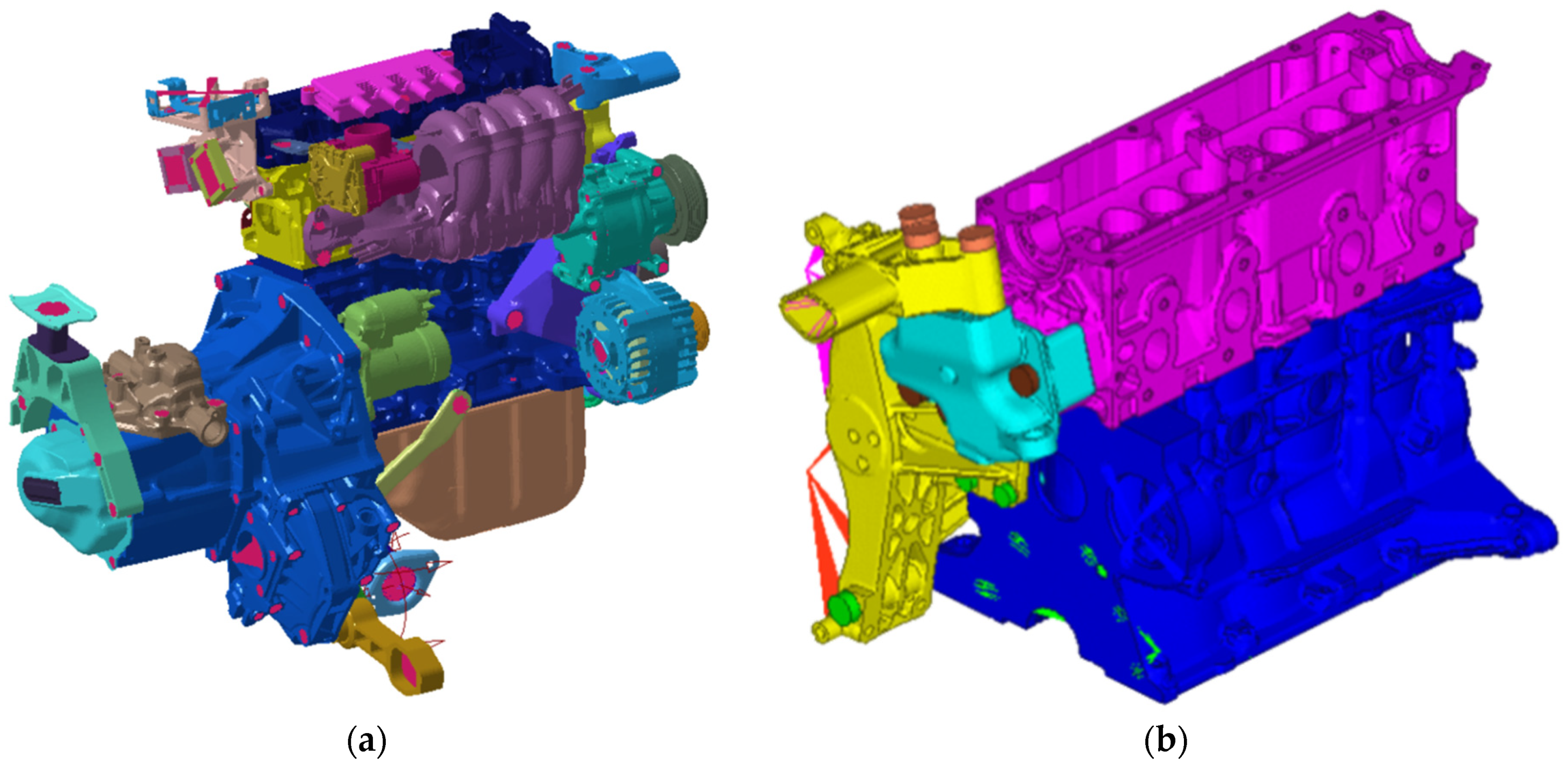
Tetrahedral quadratic elements were used to model components such as engine crankcase, cylinder head, crankshaft, gearbox, etc., whereas quadrilateral quadratic surface elements were used to model thin elements such as the exhaust pipe or the oil pan (Figure 1a). The average element size was set to 3–6 mm and the final full FEM model (Figure 1a) comprised nearly 5.7 × 10⁶ elements and 4.7 × 10⁶ nodes.
Such engine numerical model was simplified for the dynamic analysis, switching from the configuration of Figure 1a to that of Figure 1b, in such a way to reduce the computational burden. The simplification adopted was judged as acceptable within the framework of the proposed problem, as the dynamics of bracket and accessory bracket are nearly insensitive to the relatively limited engine mass reduction operated with the subtraction of the cylinder head cover and related components. Consequently, such a simplified configuration was adopted for all calculations throughout this work.
FRF analyses were adopted to evaluate the vibration behavior of the reduced model with all the bolt connections modelled in three different ways: “full 3D bolt model”, “Glue surfaces”, and “1D model”.
3. Reference 3D Modelling
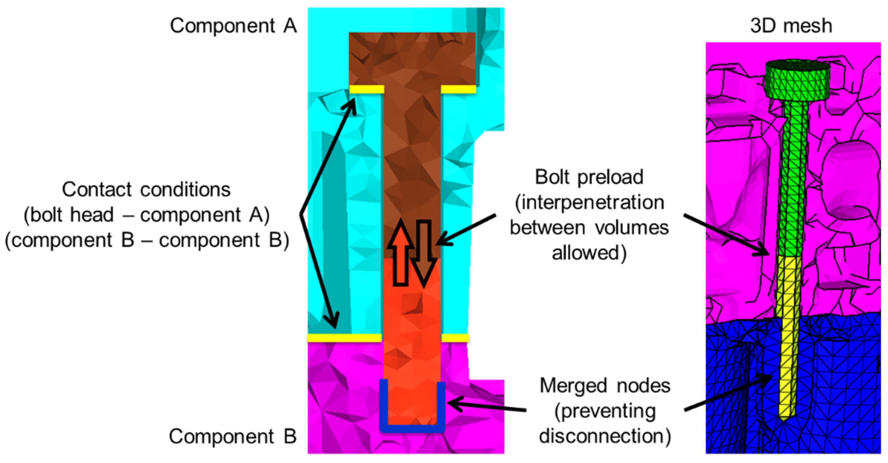
The reference and most accurate option implemented for modelling bolt connections (hereinafter “full 3D bolt model”) was based on a complete 3D FEM modelling (Figure 2), with the explicit allowance for: pretension in the bolt as caused by the tightening torque (modelled as an imposed deformation in the middle of the bolt that allows interpenetration between the two volumes); nonlinear contact with friction (friction coefficient equal to 0.15) between bolt head and components and between component surfaces to join; a fully clamped condition at the end of the bolt, with nodes of the two coupling parts merged together.
In another simplified approach, “Glue surfaces”, a preliminary nonlinear static analysis was run so as to calculate the contact surface in each connection on the basis of the imposed pretension in bolts and friction coefficient on the contact surfaces. Consequently, the nonlinear contact elements were replaced by a continuity condition for the contact areas highlighted by the previous static analysis and the linear dynamic analyses was then performed. Further details are provided in the following sections.
It is worth mentioning that explicitly modelling each bolt in his three-dimensional nature involves relevant runtimes (one-day calculus) and memory space occupation (up to 60 GB) for the linear modal analysis, despite using a powerful professional workstation.
4. FRF Analyses on the Simplified Engine Model but with Full 3D Bolt Modelling
The aim of this preliminary analysis was the validation of such 3D modelling strategy for the engine dynamic analysis, in order to subsequently adopt it as a reference for benchmarking the other two considered approaches.
An FRF analysis was run on the simplified engine model (Figure 1b) and the acceleration levels were compared with experimental acceleration measurements, obtained by an impact hammer test in-house performed on the full engine model of Figure 1a (a disassembled engine corresponding to the configuration of Figure 1b was not available in the laboratory).
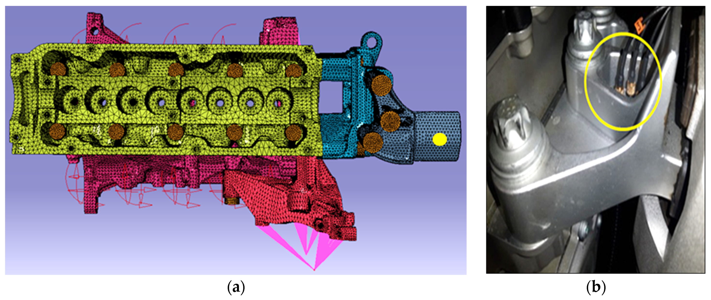
Figure 3a shows one of the experimental hammering points (in correspondence of the engine bracket), whereas Figure 3b highlights the accelerometer nearby monitoring point (yellow circle); a slight misalignment between numerical monitoring point and experimental hammering point can be expected. It is also possible noting from Figure 3a the heads of bolts explicitly modelled (brown colored elements). The cross comparison between numerical and experimental outcomes allowed the fine tuning of this modelling strategy, e.g., the damping coefficient.
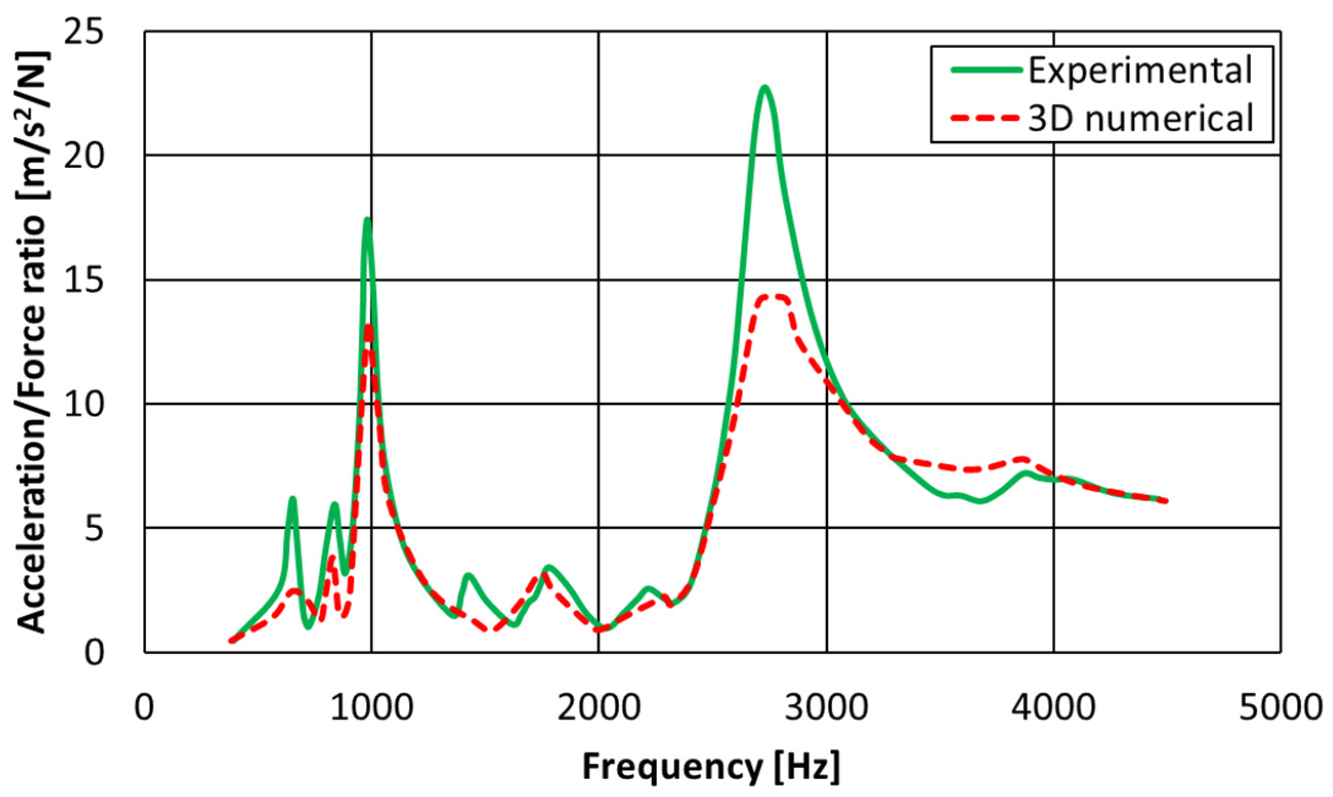
After fine tuning of this numerical model, the final numerical/experimental comparison on the inertance (accelerations/excitation force) at the hammered point, measured by an impact hammer test, is reported in Figure 4 across the whole considered frequency range (100 ÷ 4000 Hz), showing quite a satisfactory level of correlation, with perfectly overlapped eigenfrequencies. Some discrepancies can be noticed in the acceleration amplitudes and this can be attributed to two main reasons: the uncertainties on the modal damping value introduced in the dynamic simulation, equal to 3% in all the frequency range (rigorously, it should be frequency dependent) and equal for all the three different involved materials (cast iron, iron and aluminum), and to the slight mismatch between the location of the experimental hammered point and the monitoring point in the numerical model.
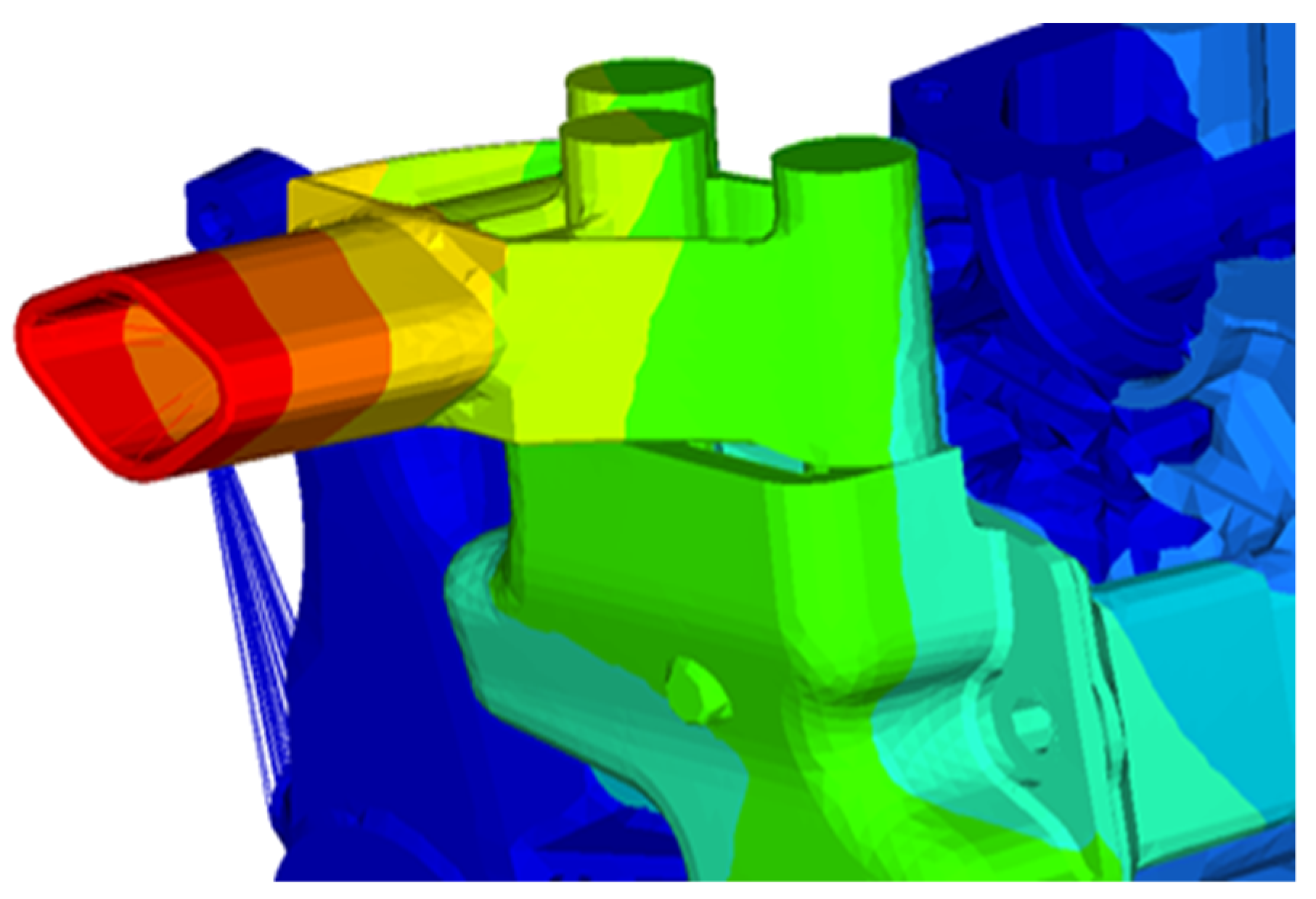
In Figure 5 the eigenmode at nearly 2700 Hz (see also Figure 4) corresponding to the first flexural mode of the engine bracket is shown. The adoption of a simplified FEM engine model allowed to significantly reduce the computational burden whereas the inherent approximations were judged as acceptable in view of satisfactory matching between numerical and experimental outcomes. As said above, the “full 3D bolt model” was considered as the reference against which benchmarking the “1D model” and “Glue surfaces” simplified modelling approaches.
5. Simplified Modelling Approaches
The following simplified modelling approaches for the bolt connections were benchmarked against the validated “full 3D bolt model”:
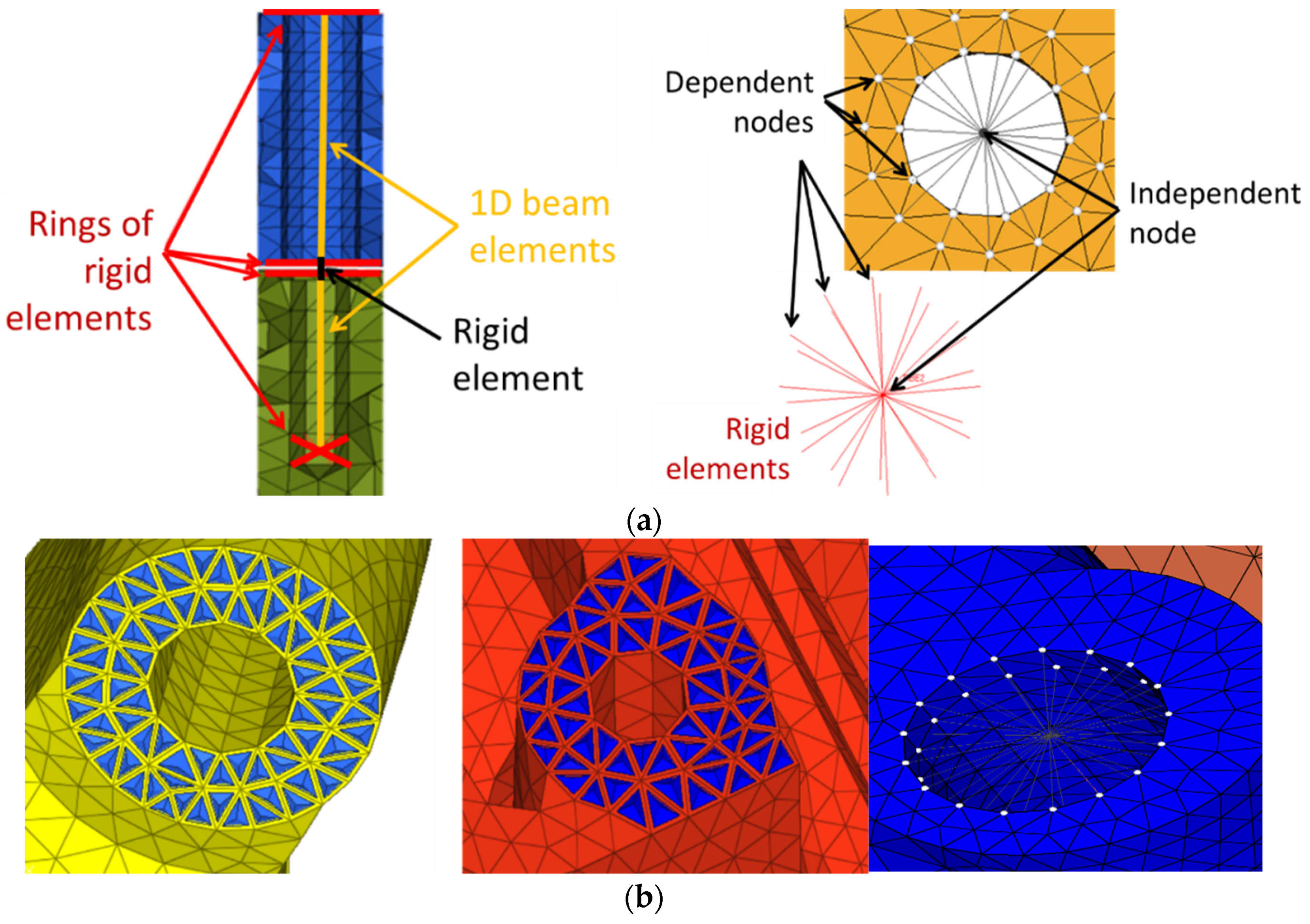
- A simplified 1D modelling (Figure 6a) based on combinations of rigid and 1D beam elements (hereinafter “1D model”). Such an approach was based on the use of beam elements (CBAR) to model the pin and rigid elements (RBE2) to connect it to the components: stars of rigid elements connecting independent central nodes on bolt axis to the surrounding dependent nodes (in this way such nodes are constrained to undergo the same displacements); an intermediate 1D rigid element was added so as to allow for slight misalignments between components (rather typical for models with many components).
- A simplified “Glue surfaces” condition where master and slave surfaces are glued together with a “freeze” contact condition (Figure 6b), namely, no relative motion is allowed between such interacting surfaces. This modelling can be considered as the simplest modelling approach among the three proposed here because the bolt is not modelled at all (consequently discarding its mass contribution). In particular, just the stiffening effect of bolts is modelled, using stars of rigid elements connecting master nodes, selected along the bolt axis, with slave nodes, selected along the internal radius of the cylindrical surface (Figure 6b).
6. Results and Discussion
FRF analyses were performed in four different positions of the hammered point in order to benchmark the two simplified approaches for bolt modelling. Results were provided for two separate frequency ranges: 0–2000 Hz and 2000–4000 Hz.
6.1. Frequency Range 0–2000 Hz
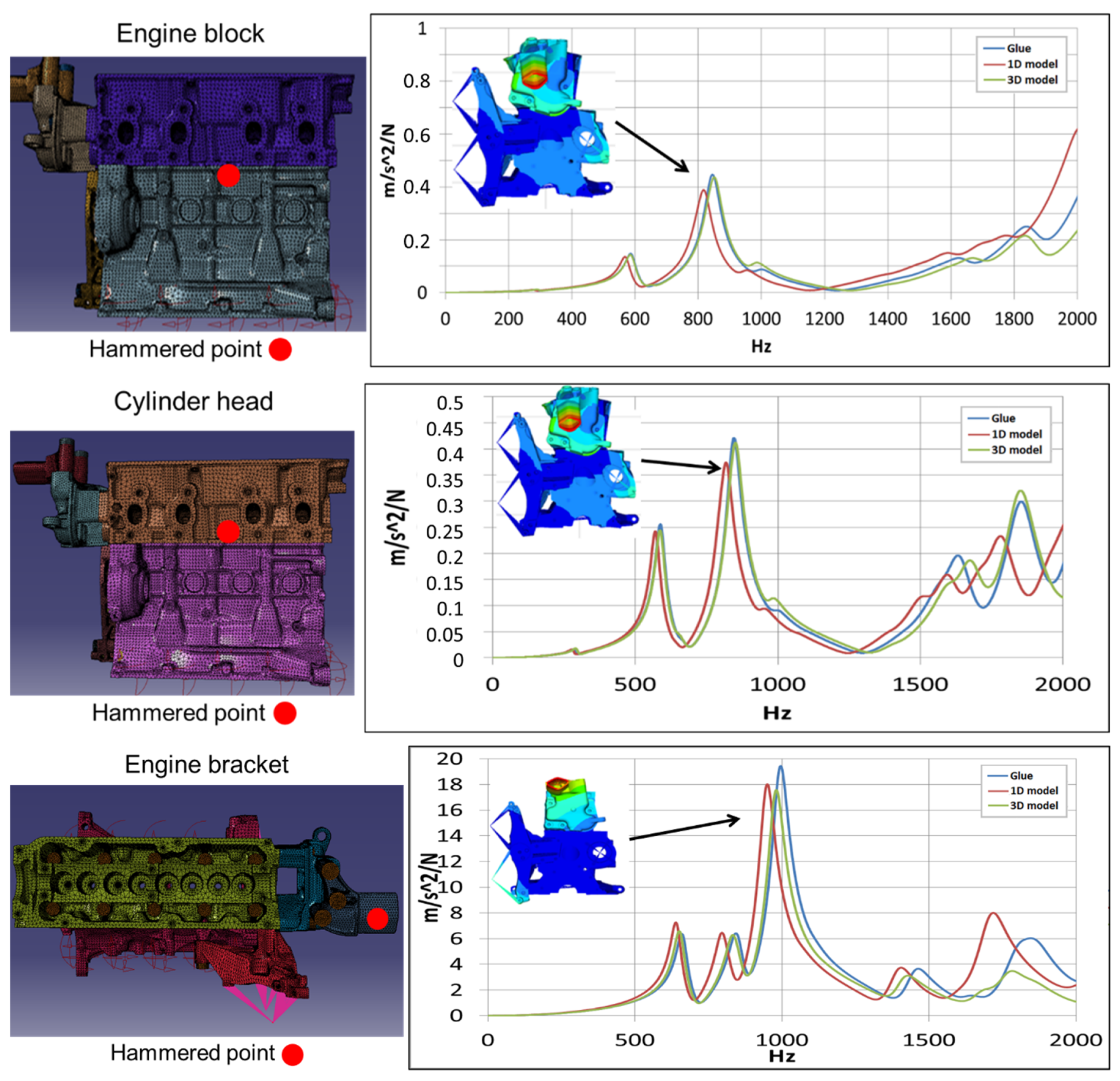
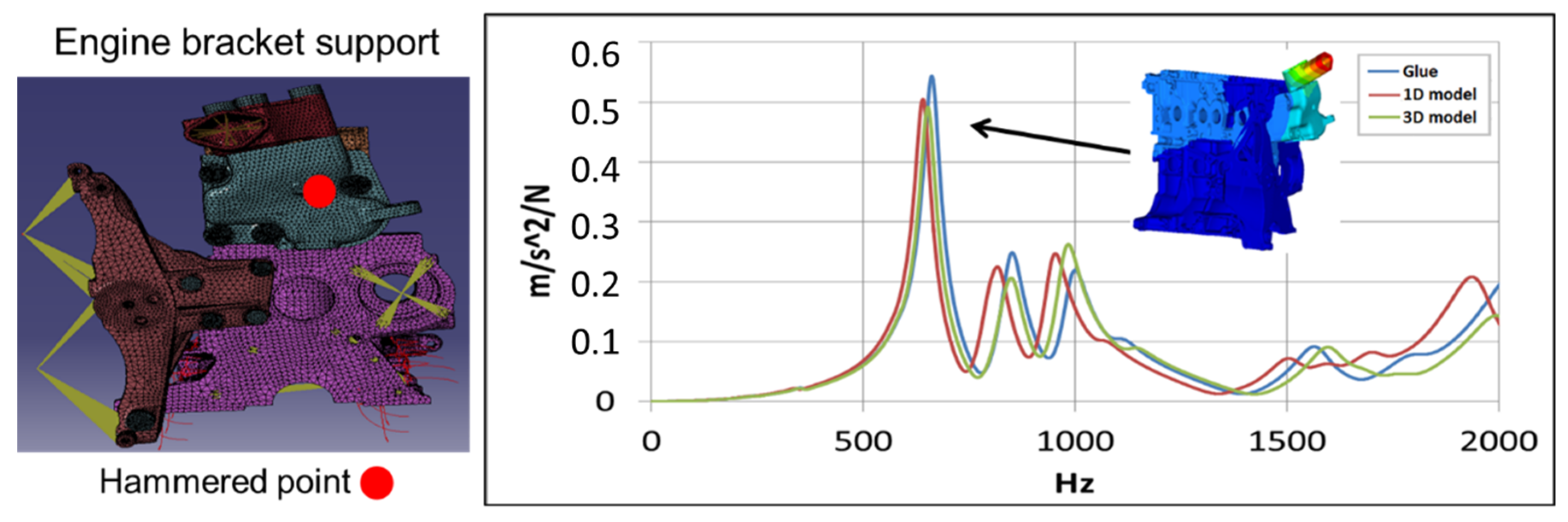
Taking as a reference the 3D modelling and considering the frequency range 0–2000 Hz, it is possible to observe that “Glue surfaces” approach works slightly better than “1D model” with respect to all the hammered positions (Figure 7).
However, as an overall, results for the three modelling approaches are mostly equivalent, since, due to the lack of local modes in the considered frequency range, the modes are mainly of a global type (Figure 7) and consequently not affected by the details of bolt modelling. Namely, the type of bolt connection modelling produces no appreciable impact because in the connection areas there is no tendency to local disconnection or, in general, no tendency to relative local motion between the connected parts.
Even if the “Glue surfaces” modelling seems to provide slightly more accurate results than the “1D model”, the latter is more advantageous for users since being a more standardized procedure (thus less prone to error) and involving lower user efforts.
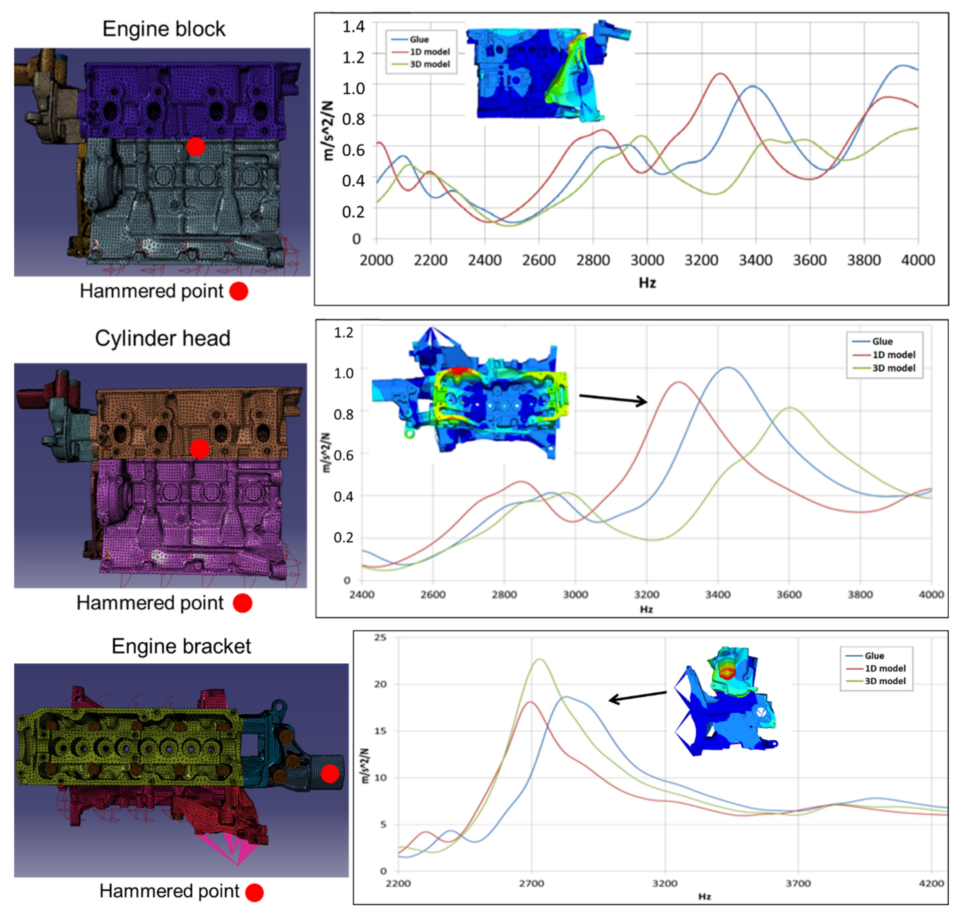
6.2. Frequency Range 2000–4000 Hz
Taking as a reference the 3D modelling and considering the frequency range 2000–4000 Hz (Figure 8), it is possible to observe that “Glue surfaces” approach works slightly better than “1D model” with respect to the cases of engine block and cylinder head whereas the reverse happens for the two remaining cases.
Such an outcome can be explained considering that a certain relative motion between components should be allowed when trying to simulate the presence of high frequency local modes. Such mobility is not allowed at all by “Glue surfaces” strategy that, consequently, turns out to be preferable when high pretension loads are applied, e.g., when considering connections between engine block and cylinder head. This is the reason of an improved correlations provided by the “1D model” approach when the excitation is on the engine block or cylinder head. On the contrary, when considering the hammering point either on the bracket or on bracket support, the tightening torque of the related bolt connections is lower and lower is also the overall stiffness of the component, asking for a less stiff connection as provide by “1D model”, which provides better correlations.
In conclusion, at a frequency ranging in 2 ÷ 4 kHz, glued surfaces provided slight accuracy improvements in comparison with the “1D model” when high pretension loads are applied, whereas the reverse happens for low pretension load.
7. Conclusions
Three FEM modelling approaches for the numerous bolts interconnecting the components of a petrol engine were compared in terms of computational burden, preprocessing time, and modelling accuracy. FRF analyses were selected to characterize the vibration response of a reduced model of the engine, when different approaches were adopted for modelling bolts.
As a matter of fact, the 3D FEM modelling presented relevant drawbacks in terms of memory requirements (30 to 60 GB of memory occupation) and runtimes (up to two days’ calculus to obtain the needed FRFs) for a full engine dynamic analysis.
At relatively low frequencies (<2000 Hz), gluing the surfaces turned out to provide a slight accuracy improvement but at expenses of runtimes and preprocessing times. Using the “1D model” was more advantageous for users since it is standardized company procedure, consequently less prone to error and involving a lower user effort.
At higher frequency and when high pretension loads are needed, “Glue” provided a slight accuracy improvement in comparison with “1D model”, whereas the reverse happened for low pretension load.
Compared to “1D model”, the “Glue” approach increased computational time since additional equations had to be solved to take into account the interactions between surfaces. Such an increase could be estimated at +20%.
“1D model” did not increase preprocessing time significantly, since creation of 1D bolts was automated and allowed for completing a modal analysis up to 4000 Hz with 6 h of runtime.
In conclusion, the “1D model” approach could be envisaged as the recommended one for a simplified modelling of the bolt connections, thanks to its substantial advantages in terms of preprocessing times and, at the same time, providing a comparable accuracy with “Glue” approach.
Author Contributions
Conceptualization E.A. and R.C.; methodology, V.G. and R.S.; software, V.G.; formal analysis, V.G. and R.S.; investigation, V.G.; writing—original draft preparation, R.S. and R.C.; writing—review and editing, R.S., R.C., and E.A.; supervision, E.A. and R.C. All authors have read and agreed to the published version of the manuscript.
Funding
This research received no external funding.
Institutional Review Board Statement
Not applicable.
Informed Consent Statement
Informed consent was obtained from all subjects involved in the study.
Data Availability Statement
The data presented in this study are available on request from the corresponding author.
Conflicts of Interest
The authors declare no conflict of interest.
References
- Citarella, R.; Landi, M. Acoustic analysis of an exhaust manifold by Indirect Boundary Element Method. Open Mech. Eng. J. 2011, 5, 138–151. [Google Scholar] [CrossRef] [Green Version]
- Citarella, R.; Federico, L. Advances in Vibroacoustics and Aeroacustics of Aerospace and Automotive Systems. Appl. Sci. 2018, 8, 366. [Google Scholar] [CrossRef] [Green Version]
- Armentani, E.; Giannella, V.; Parente, A.; Pirelli, M. Design for NVH: Topology optimization of an engine bracket support. Procedia Struct. Integr. 2020, 26, 211–218. [Google Scholar] [CrossRef]
- Giannella, V.; Lombardi, R.; Pisani, M.M.; Federico, L.; Barbarino, M.; Citarella, R. A novel Optimization Framework to Replicate the Vibro-Acoustics Response of an Aircraft Fuselage. Appl. Sci. 2020, 10, 2473. [Google Scholar] [CrossRef] [Green Version]
- Bianco, D.; Adamo, F.P.; Barbarino, M.; Vitiello, P.; Bartoccini, D.; Federico, L.; Citarella, R. Integrated Aero–Vibroacoustics: The Design Verification Process of Vega-C Launcher. Appl. Sci. 2018, 8, 88. [Google Scholar] [CrossRef] [Green Version]
- Armentani, E.; Sbarbati, F.; Perrella, M.; Citarella, R. Dynamic analysis of a car engine valve train system. Int. J. Veh. Noise Vib. 2016, 12, 229–240. [Google Scholar] [CrossRef]
- Armentani, E.; Giannella, V.; Citarella, R.; Parente, A.; Pirelli, M. Substructuring of a Petrol Engine: Dynamic Characterization and Experimental Validation. Appl. Sci. 2019, 9, 4969. [Google Scholar] [CrossRef] [Green Version]
- Armentani, E.; Trapani, R.; Citarella, R.; Parente, A.; Pirelli, M. FEM-BEM Numerical Procedure for Insertion Loss Assessment of an Engine Beauty Cover. Open Mech. Eng. J. 2013, 7, 27–34. [Google Scholar] [CrossRef]
- Yorgun, C.; Dalcı, S.; Altay, G.A. Finite element modeling of bolted steel connections designed by double channel. Comput. Struct. 2004, 82, 2563–2571. [Google Scholar] [CrossRef]
- Schwingshackl, C.; Petrov, E. Modeling of Flange Joints for the Nonlinear Dynamic Analysis of Gas Turbine Engine Casings. J. Eng. Gas Turbines Power 2012, 134, 122504. [Google Scholar] [CrossRef]
- Lacayo, R.; Pesaresi, L.; Groß, J.; Fochler, D.; Armand, J.; Salles, L.; Schwingshackl, C.; Allen, M.; Brake, M. Nonlinear modeling of structures with bolted joints: A comparison of two approaches based on a time-domain and frequency-domain solver. Mech. Syst. Signal Process. 2019, 114, 413–438. [Google Scholar] [CrossRef] [Green Version]
- Guzas, E.; Behan, K.; Davis, J. 3D Finite Element Modeling of Single Bolt Connections under Static and Dynamic Tension Loading. Shock Vib. 2015, 2015, 205018. [Google Scholar] [CrossRef] [PubMed] [Green Version]
- Bhonge, P.S.; Foster, B.D.; Lankarani, H.M. Finite Element Modeling and Analysis of Structural Joints Using Nuts and Bolts. In Proceedings of the ASME 2011 International Mechanical Engineering Congress and Exposition, IMECE2011, Denver, CO, USA, 11–17 November 2011. [Google Scholar]
- Schwingshackl, C.W.; di Maio, D.; Sever, I.; Green, J.S. Modeling and Validation of the Nonlinear Dynamic Behavior of Bolted Flange Joints. J. Eng. Gas Turbines Power 2013, 135, 122504. [Google Scholar] [CrossRef]
- KimaJoo, J.; Beom, C.Y.; Kang, S. Finite element analysis and modeling of structure with bolted joints. Appl. Math. Model. 2007, 31, 895–911. [Google Scholar] [CrossRef]
- Liao, X.; Zhang, J.; Xu, X. Analytical Model of Bolted Joint Structure and Its Nonlinear Dynamic Characteristics in Transient Excitation. Shock Vib. 2016, 2016, 8387497. [Google Scholar] [CrossRef] [Green Version]
- Belardi, V.G.; Fanelli, P.; Vivio, F. Theoretical definition of a new custom finite element for structural modeling of composite bolted joints. Compos. Struct. 2021, 258, 113199. [Google Scholar] [CrossRef]
- Belardi, V.G.; Fanelli, P.; Vivio, F. A novel composite bolted joint element: Application to a single-bolted joint. Procedia Struct. Integr. 2018, 12, 281–295. [Google Scholar] [CrossRef]
- Li, P.; Li, W.; Wei, P.; Wang, Q. Research on finite element analysis and modelling of bolted joint. In IOP Conference Series: Materials Science and Engineering; IOP Publishing: Bristol, UK, 2020. [Google Scholar] [CrossRef]
- Lu, S.; Hua, D.; Li, Y.; Li, P. Establishment and Verification of Nonlinear Bolt Head Connection Stiffness Theoretical Model Based on Levenberg-Marquardt Method. IEEE Access 2020, 8, 189354–189364. [Google Scholar] [CrossRef]
- Armentani, E.; Caputo, F.; Esposito, L.; Citarella, V.G.R. Multibody Simulation for the Vibration Analysis of a Turbocharged Diesel Engine. Appl. Sci. 2018, 8, 1192. [Google Scholar] [CrossRef] [Green Version]
- Altair Engineering. Hypermesh User Manual; Altair Engineering: Troy, MI, USA, 2011. [Google Scholar]
- SIEMENS-LMS Virtual Lab. User Manual; SIEMENS-LMS Virtual Lab: Plano, TX, USA, 2011. [Google Scholar]
Figure 1.
(a) Full CAD model of the 4-cylinder 4-stroke petrol engine; (b) simplified model adopted for the FEM simulations.
Figure 1.
(a) Full CAD model of the 4-cylinder 4-stroke petrol engine; (b) simplified model adopted for the FEM simulations.

Figure 2.
Full 3D modelling of bolts, with highlight of nonlinear contact and pretension in the bolt shank.
Figure 2.
Full 3D modelling of bolts, with highlight of nonlinear contact and pretension in the bolt shank.

Figure 3.
FEM simplified model with highlight of the reference position (yellow dot) for vibration excitation (a) and acceleration measurement nearby location (b).
Figure 3.
FEM simplified model with highlight of the reference position (yellow dot) for vibration excitation (a) and acceleration measurement nearby location (b).

Figure 4.
Experimental and numerical (“full 3D”) inertance vs. frequency measured at engine bracket, with excitation in the same point (highlighted in Figure 3a).
Figure 4.
Experimental and numerical (“full 3D”) inertance vs. frequency measured at engine bracket, with excitation in the same point (highlighted in Figure 3a).

Figure 5.
Eigenmode at nearly 2700 Hz (Figure 4) with highlight of engine bracket response.
Figure 5.
Eigenmode at nearly 2700 Hz (Figure 4) with highlight of engine bracket response.

Figure 6.
(a) 1D simplified approach with rigid and elastic beam elements; (b) approach with “Glue surfaces”, with highlight of contact continuity conditions (left-center) and star of rigid elements (right).
Figure 6.
(a) 1D simplified approach with rigid and elastic beam elements; (b) approach with “Glue surfaces”, with highlight of contact continuity conditions (left-center) and star of rigid elements (right).

Figure 7.
FRFs in the frequency range 0–2000 Hz, for the four hammered positions with highlight of eigenmodes related to the highest resonance amplitudes.
Figure 7.
FRFs in the frequency range 0–2000 Hz, for the four hammered positions with highlight of eigenmodes related to the highest resonance amplitudes.


Figure 8.
FRFs in the frequency range 2000–4000 Hz, for the four hammered positions with highlight of eigenmodes related to the highest resonance amplitudes.
Figure 8.
FRFs in the frequency range 2000–4000 Hz, for the four hammered positions with highlight of eigenmodes related to the highest resonance amplitudes.


Publisher’s Note: MDPI stays neutral with regard to jurisdictional claims in published maps and institutional affiliations. |
© 2021 by the authors. Licensee MDPI, Basel, Switzerland. This article is an open access article distributed under the terms and conditions of the Creative Commons Attribution (CC BY) license (https://creativecommons.org/licenses/by/4.0/).
Share and Cite
MDPI and ACS Style
Giannella, V.; Sepe, R.; Citarella, R.; Armentani, E. FEM Modelling Approaches of Bolt Connections for the Dynamic Analyses of an Automotive Engine. Appl. Sci. 2021, 11, 4343. https://doi.org/10.3390/app11104343
AMA Style
Giannella V, Sepe R, Citarella R, Armentani E. FEM Modelling Approaches of Bolt Connections for the Dynamic Analyses of an Automotive Engine. Applied Sciences. 2021; 11(10):4343. https://doi.org/10.3390/app11104343
Chicago/Turabian StyleGiannella, Venanzio, Raffaele Sepe, Roberto Citarella, and Enrico Armentani. 2021. "FEM Modelling Approaches of Bolt Connections for the Dynamic Analyses of an Automotive Engine" Applied Sciences 11, no. 10: 4343. https://doi.org/10.3390/app11104343
Note that from the first issue of 2016, this journal uses article numbers instead of page numbers. See further details here.