
Position Control for Soft Actuators, Next Steps toward Inherently Safe Interaction


Department of Electrical and Computer Engineering, University of California, Santa Cruz, CA 95064, USA
*
Author to whom correspondence should be addressed.
Electronics 2021, 10(9), 1116; https://doi.org/10.3390/electronics10091116
Submission received: 13 April 2021
/
Revised: 5 May 2021
/
Accepted: 6 May 2021
/
Published: 9 May 2021
(This article belongs to the Special Issue Human Computer Interaction and Its Future)
Abstract
:Soft robots present an avenue toward unprecedented societal acceptance, utility in populated environments, and direct interaction with humans. However, the compliance that makes them attractive also makes soft robots difficult to control. We present two low-cost approaches to control the motion of soft actuators in applications common in human-interaction tasks. First, we present a passive impedance approach, which employs restriction to pneumatic channels to regulate the inflation/deflation rate of a pneumatic actuator and eliminate the overshoot/oscillation seen in many underdamped silicone-based soft actuators. Second, we present a visual servoing feedback control approach. We present an elastomeric pneumatic finger as an example system on which both methods are evaluated and compared to an uncontrolled underdamped actuator. We perturb the actuator and demonstrate its ability to increase distal curvature around the obstacle and maintain the desired end position. In this approach, we use the continuum deformation characteristic of soft actuators as an advantage for control rather than a problem to be minimized. With their low cost and complexity, these techniques present great opportunity for soft robots to improve human–robot interaction.
1. Introduction
From factory automation to Roombas, robots make our lives easier, safer, and more efficient. Robots have seen great success in structured unpopulated environments. However, built of rigid links actuated by powerful motors, traditional robots are fundamentally unsuited for interaction with humans. Typically cordoned off from populated areas or even separated by heavy walls, accidents with humans are rare but often deadly. In their entire history, robots have only been cited in 45 OSHA accident reports, but 30 of those involved a fatality [1]. With large electric motors and precise controllers, robots capable of meaningful work are generally heavy and expensive, placing them out of reach for most household uses. To bring robots into the home and populated workplace, the collaborative robot (cobot) movement has primarily made them small, slow, or both (Roomba, Universal Robot, Rethink Robot) [2,3], to render them incapable of catastrophic physical harm. Built from inherently deformable inexpensive materials, soft robots promise to resolve the fundamental issues of impedance match and cost. Furthermore, soft robots are exceedingly well positioned to leverage techniques from bioinspired design, drawing motivation from nature and how living organisms move and interact with their environment [4]. Built from low modulus materials including hydrogels [5], silicone elastomers [6,7,8,9,10], or flexible-inextensible materials such as reinforced fabrics [11,12], soft robots are able to conform to their environment promising exciting new opportunities in manipulation and human–robot interaction. Taking advantage of soft robotics’ adaptable nature, research has integrated obstacle contact to these robots to simplify navigation [13]. Multisegmented, proximally actuated soft robotic fingers have achieved high precision by pinch grasping [14].
However, the flexibility that provides so much promise has made the use of traditional control techniques insufficient for soft robots. The softer and more compliant the robot, the more unpredictable and difficult it is to control [15]. While control efforts have largely shifted to machine learning techniques, especially those involving artificial neural networks (ANN) [16,17,18,19], model-based techniques have been pursued. Sensor measurement error [20,21] techniques show promise but remain preliminary. Finite Element Analysis (FEA) is a well-established technique for analyzing continuously deformable structures, but computing complexity prevents the widespread real-time analysis needed for control. One sensor-based approach consists of embedding commercially available bending sensors into the soft robotic gripper [22,23]. However, this approach causes excessive wear and rupture on most systems [21]. Inherently soft resistive and capacitive sensors [20,24,25] have been presented in which geometry changes cause a change in sensor resistance or capacitance. Capable of robust sensor measurements, these systems have been used widely in the aforementioned ANN techniques.
We propose two control approaches for pneumatic soft actuators used in human-centric environments.
Our first approach uses overall passive impedance to maximize the speed with which an actuator reaches its setpoint while minimizing actuator overshoot and subsequent “ringing”. In this method, the impedance of the system’s pneumatic system (both inflow and outflow of gas) is manually tuned using passive elements including tubing of various lengths and diameter as well as orifices.
Our second approach uses real-time visual servoing to control a soft robot actuator using motion tracking markers and a low-cost CCD camera. This approach is well suited for human–robot interaction applications such as patient care or household robots (cobots) [26,27]. By focusing on human-interaction tasks, we narrow our evaluation to characteristic behaviors on the human-scale in dimension, speed, and accuracy. Populated environments are often adequately illuminated with line-of-sight access to tasks unlike deep-sea or pipeline applications.
We draw inspiration from nature and the process humans use for gripping tasks. In addition to proprioceptive feedback, humans rely heavily on visual perception of the hand’s position relative to an object of interest, especially prior to contact, after which haptic feedback may dominate. In the proposed method, a CCD camera acts to perceive markers adhered to a soft robot finger, and a motion-tracking algorithm implements PD control to maintain a desired finger position. This control loop maintains finger position in both a free displacement state and when external forces perturb finger actuation. Recent work at Delhi Technological University included CCD cameras as one component in soft robotic control loop, but the system still requires a traditional curvature embed sensors inside the actuator [28]. Traditional, on-board sensing is an excellent option in many cases. However, as described above, robust control techniques remain elusive, and they often include sensors that are costly, contain toxic chemicals, or damage the actuator over time. Our proposed passive impedance approach provides a near-zero cost option for rapid actuation while minimizing overshoot with no additional components. Our visual servoing feedback control approach uses no onboard sensors, and only a remote CCD camera (often available on robot systems) to obtain reliable position control, minimizing the ambiguity of actuator position.
2. Materials and Methods
In this work, we demonstrate two techniques to control the movement of a soft pneumatic finger-shaped actuator. In the first method, we control the flow of air to and from the actuator via restriction in the flow line (tuned impedance). In the second method, we use PD control of real-time video data to control the position of markers mounted to the actuator (visual servoing). This position data are used to inform pressure setpoint and thereby actuation, resulting in closed loop control of finger position.
2.1. Actuator Design
Similar in concept to many recent pneumatic soft actuators [24,29,30], our device consists of a network of bladders that actuated non-uniformly to produce bending actuation when inflated (Figure 1). While this system can be instrumented with onboard sensors similar to our previous work [20], those sensors were not needed for either the tuned impedance or visual servoing methods presented here and were not included in the current system. The actuator was fabricated using common, inexpensive layered molding techniques [6]. The individual layers were fabricated of readily available elastomer, Dragon Skin 10 (Smooth-On, Inc. Macungie, PA, USA) in molds 3D printed from a widely available low-cost 3D Printer (Prusa i3, Prusa Research, Prague, Czech Republic). By eliminating complex internal vasculature and onboard ionogel sensors, this actuator (or similar designs) can be readily fabricated using tools available at most universities (and even many high schools), maintaining a spirit of accessible technology that is one goal of this work.
The actuator was plumbed with a pneumatic line and fastened to a mount system in a rigid frame (Figure 2). The finger was instrumented with tracking markers consisting of circular markers, 8 mm diameter, of cardstock material adhered to the surface of the finger. Retroflective spherical markers were considered but rejected. This analysis tracks planar motion only, contrast between black markers and a near-white actuator provided excellent contrast, and the additional complexity of retroflective markers deviates from the philosophy of low-cost accessible technology embraced in this work.
2.2. System Configuration
A small CCD camera (Lifecam, Microsoft Corp, Redmond, WA, USA) was mounted normal to the finger plane of motion, and exposure was set to maximize contrast between black markers and surrounding off-white finger and environment. The USB CCD camera was connected to a PC with our marker tracking and control software (see motion capture section), and microcontroller (Arduino nano, Adafruit Industries, New York, NY, USA). The controller output an analog voltage to a pressure regulator (ITV2010-31N2L4, SMC Corp, Noblesville, IN, USA), which increased or decreased air pressure to the actuator as needed (Figure 3). The control signal was passed through a digital-to-analog converter (DAC) (MCP4725, Adafruit Industries, New York, NY, USA), to output a proportional analog voltage. Finally, the DC voltage was applied on the pressure regulator to maintain target pressure.
2.3. Uncontrolled Actuator
To serve as a basis for comparison, we instrumented an uncontrolled silicone finger actuator with supply line and connected it to our evaluation system. We recorded video of the finger actuating followed by venting. For this experiment, inflation plumbing consisted of a ball valve and a short length (≈10 cm) of tubing (3 mm od, 1.5 mm id). Exhaust plumbing consisted of similar tubing (≈5 cm) and a relief valve. Video data were analyzed to display uncontrolled system dynamics for comparison with the two approaches that follow.
2.4. Approach I, Passive Impedance
In this approach, we modulate restriction along system pneumatic lines to limit gas supply and vent rates. This upstream and downstream impedance is tuned to minimize actuator overshoot in approaching a setpoint while minimizing time to reach that setpoint. Taking inspiration from vibration analysis, this can be thought of as conceptually equivalent to a critically damped pneumatic supply/actuator system. Although this is not truly a critically damped system, as we are not directly tuning the damping of the mechanical system, this description is a useful colloquial analogy but not a strict definition.
In order to achieve this pseudo-critical damping, we instrumented an elastomeric finger actuator (Figure 2) as a baseline value for impedance. The configuration included luer-lock access needle, pneumatic solenoid valve (Parker X valve 912-000001-003, Parker Hannifin, Hollis, NH, USA), minimal required tubing, and fittings. Next, we added tubing (3 mm od, 1.5 mm id) between the solenoid valve and luer-lock needle until the actuator no longer overshot its setpoint when actuated. In a real system, this will allow for sufficient plumbing to route lines from the supply to the actuator. Many possible configurations (long narrow tubing, one orifice, several plumbing components) are possible as long as overall impedance is tuned.
2.5. Approach II, Closed Loop Visual Servoing
Using visual servoing of tracking marker positions in a series of video frames, we estimated the position of points along a soft finger actuator and used this data to control the finger position. This system uses a PD controller with an input of pixel coordinates from tracking markers and outputs the required voltage for the air regulator to supply air pressure to the actuator.
While many image processing techniques are available, each has its relative advantages and limitations. We considered the General Hough Transform, image subtraction, and Blob Detection options. The General Hough Transform is a feature extraction technique that detects lines in an image. This technique is a transformation of a point in the x-y plane to the parameter space. Using a polar coordinate representation, it inscribes circles on edge points to find the center of the detention circle. This method yielded an unacceptable number of missed registrations; thus, it was not selected. Image Subtraction is the simplest image filtering method used to detect motion, in which each image has the previous image in the sequence subtracted from it, pixel by pixel. The absolute value of the difference determines if the moving object is dynamic or static [31]. In tuning this approach, one sets sensitivity for maximum correct detections (very few missed detections), while minimizing false detections (detecting a marker where there is none) or swapped detections (identifying one marker as another). In our real-world scenario involving large- and small-scale motion at varying speeds, this approach was unable to reliably identify markers correctly without a considerable number of false detections and swapped detections. This method is believed to be reliable only under a narrow band of lighting and motion conditions. Blob detection is an algorithm designed to detect regions that contrast surrounding areas; it is not limited to detecting certain shapes as in the Hough Circle Algorithm. A low-complexity method, this tracking point detection technique is able to track points quickly and critical for real-time applications. Drawing from this method to reduce delay, our approach utilized the minimum area and circularity parameters of the detections to find targets. Properly tuning those area and circularity parameters allowed us to reduce missed registrations to near zero. Details of the coding strategy and pseudocode are included in the Supplementary Information Section.
In our selected method, based on the Blob Detection theory, we track the frame from left to right, top to bottom. Since the OpenCV tracking functions cannot guarantee that the first point in one frame would still be the same spot of the three reference points, the data points need to be correctly classified before sending it to the feedback control loop. The most straightforward reference point to categorize is the one closest to the pivot point because it has the least significant change as the actuator bends. On inspecting the csv file, this point has two major features: the most significant x coordinates through the end and the smallest or second y coordinates. For the rest of the points, we found one critical moment at which Point B and Point C have the same y coordinates. Second to Point A, Point C had the smallest y coordinates after they were sorted. Once these three points were sorted correctly at any bending angle, we added two more points for a total of five tracking points. For further detail, see Appendix A.
2.6. Experiments
For each of the three configurations (uncontrolled, passive impedance, visual servoing feedback control), the system was mounted on a test platform and plumbed with pneumatic connection for fill and vent (Figure 2). To characterize motion, the uncontrolled actuator was cycled through its range of motion, and the marker position was tracked. A square wave of gas pressure was applied (step up, hold, vent) to characterize actuator oscillation in an uncontrolled state. For the passive impedance approach, a square wave was input to characterize the actuation and evaluate the minimization of overshoot. For the visual servoing feedback control approach, two target heights were set (Y value) of the most distal marker to emulate a square wave input. Pressure and displacement vs. time were recorded as the control system alternated between the two heights. Finally, a perturbation experiment was performed, in which a target height was set, an external perturbation was imposed (deflect the finger with a wooden dowel), and we evaluated the system’s ability to maintain the y-height of the distal-most marker.
3. Results
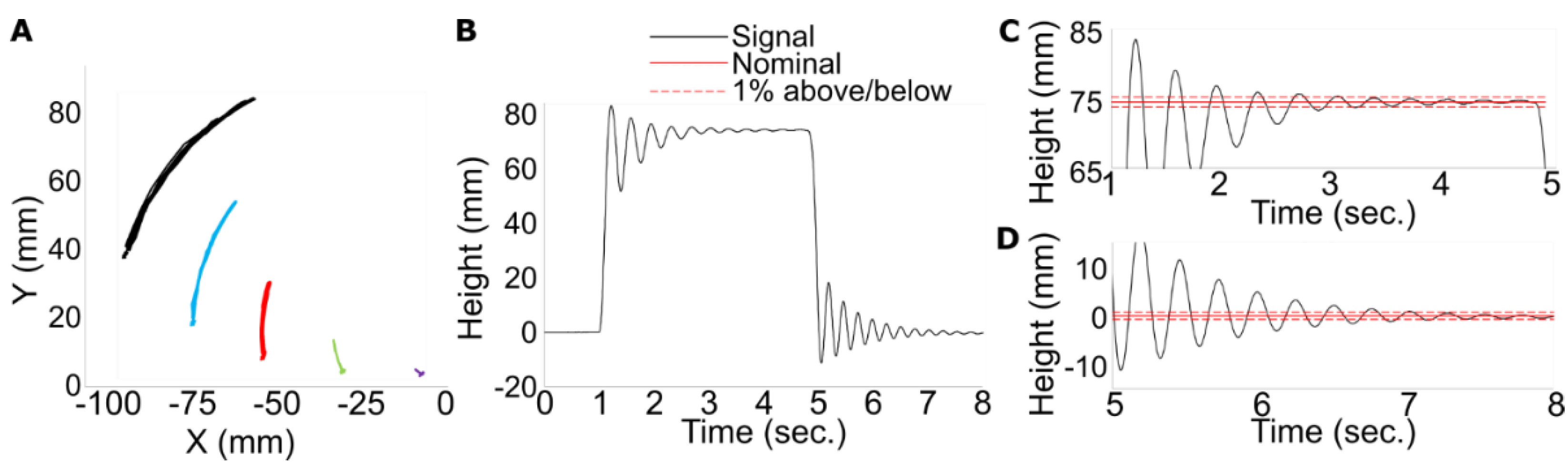
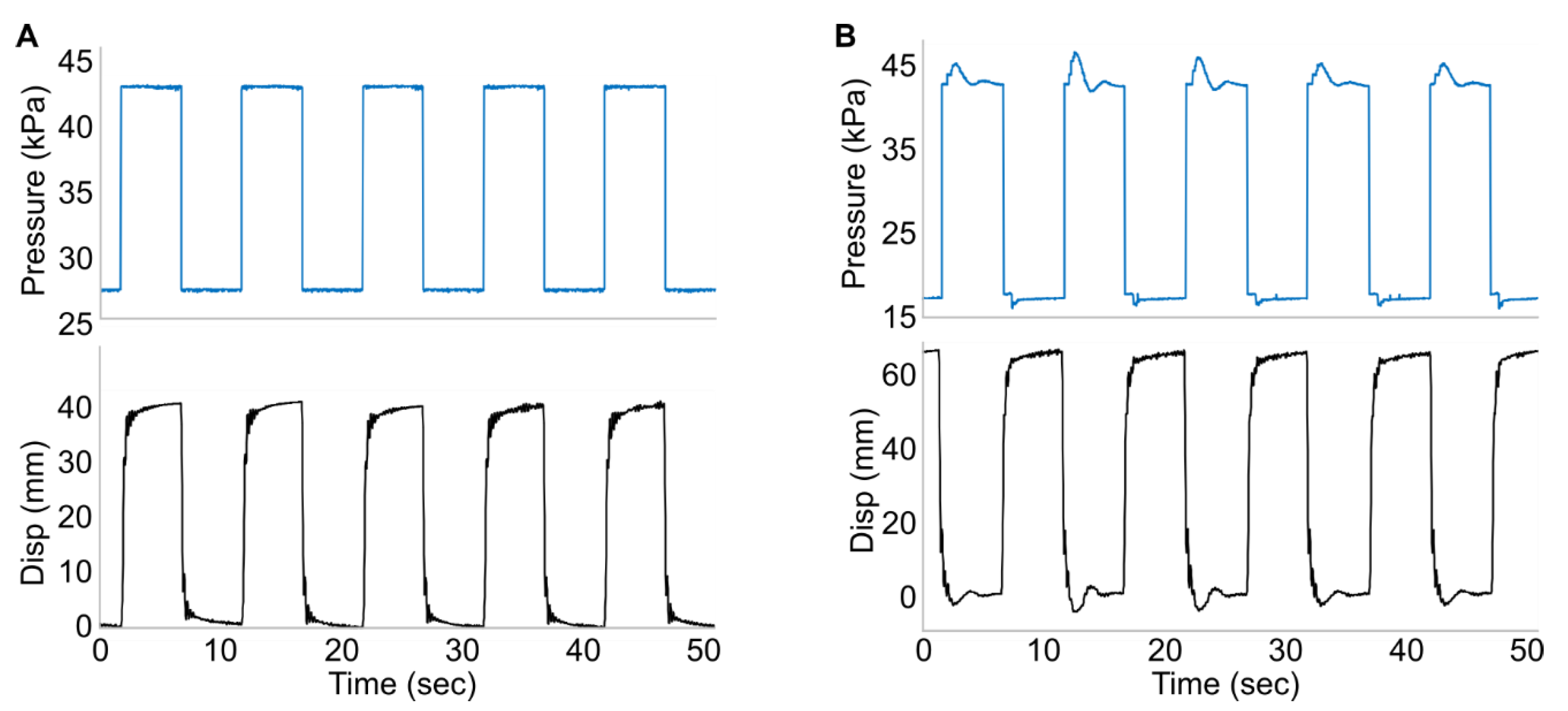
The initial (uncontrolled) actuator was cycled through its range of motion, and markers were tracked and processed. The resulting range of motion curves is presented in Figure 3A. The actuator was inflated and subsequently deflated to show performance characteristics. Resulting marker tracking analysis is shown in Figure 3B. These results serve as a representation of a typical underdamped silicone elastomer similar to the performance of many silicone soft robot actuators. We observe that rapid inflation/deflation (Figure 3B) shows considerable overshoot and multiple cycles of oscillation before settling on the final setpoint. This can be seen in both inflation and deflation. Using the two methods described above essentially eliminated overshoot and allowed rapid actuation to a final position (Figure 4). Figure 4A demonstrates the passive impedance method, which is characterized by an initial sharp rise followed by a slower rise in displacement. This initial rapid displacement followed by a slow ramp is not uncommon in elastomeric soft robot actuators. This behavior is understood to be caused by an initial inflation of the elastomeric tube (rapid) followed by gradual stress-relaxation from the viscoelastic behavior of the actuator material (slow). Based on task parameters, impedance can be tuned to achieve full actuation prior to elastomer relaxation or after a pre-selected extended period. Figure 4B demonstrates the visual servoing feedback control method, with characteristic initial rise followed by repeated adjustment of input pressure to regulate displacement without overshoot. Gain parameters here have been set to achieve inflation rapidly with approximately zero overshoot. However, the gain can be tuned to increase velocity (with some overshoot), or if task specifics require absolute assurance that there is no overshoot, gain can be tuned to damp actuation even more (at the expense of actuation velocity) and assure zero overshoot.
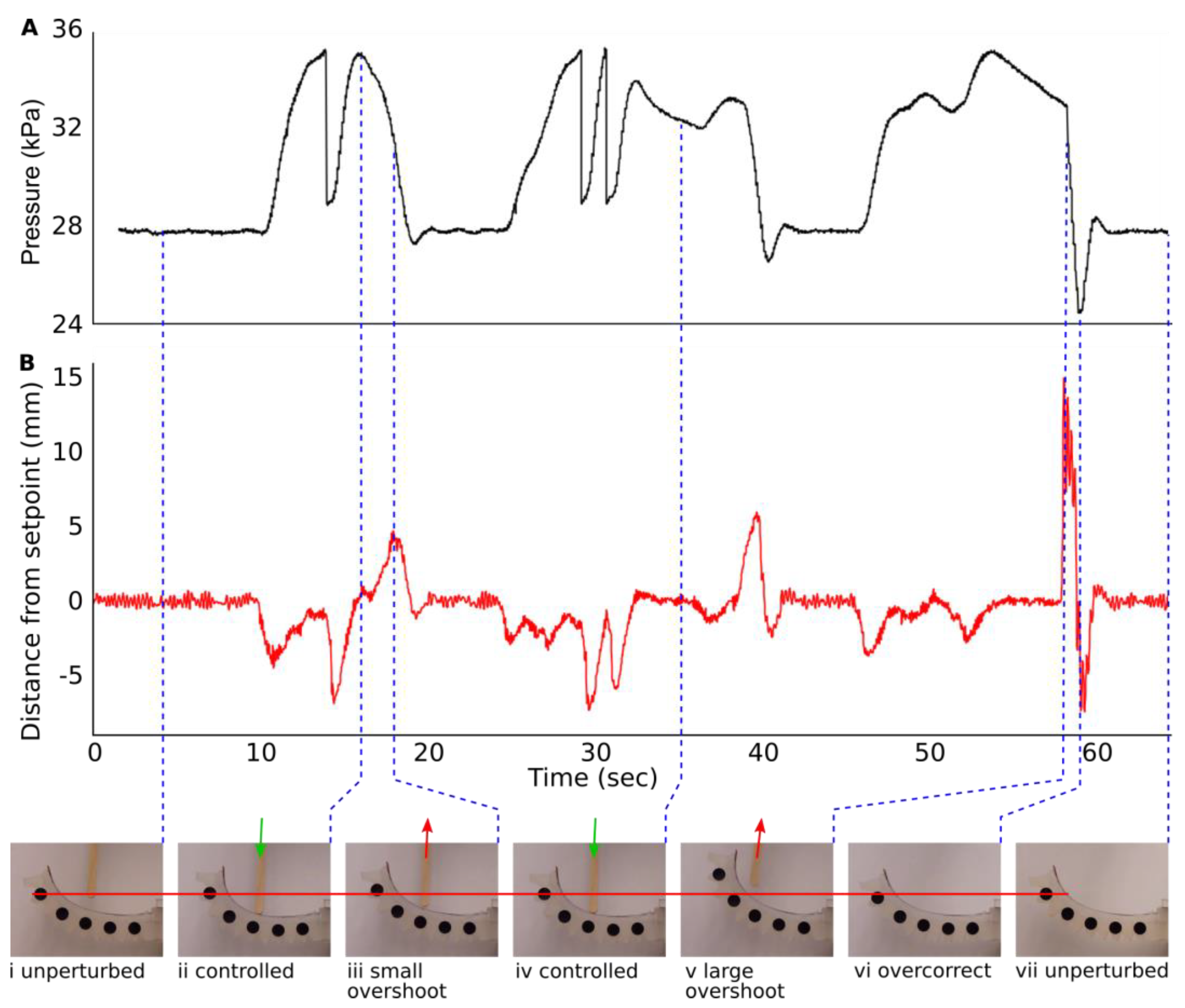
In Figure 5, the controller sets the finger at a selected height (here called Zero). An external force is applied (via a wooden dowel) halfway between the distal and proximal ends of the finger (near marker #3), perturbing the finger from its setpoint. The controller is able to increase distal bend curvature to regain the target height. When the force is removed slowly, the finger retains the setpoint with minimal overshoot. When the external force is removed quickly, considerable overshoot is seen, but the finger is able to regain setpoint.
The reference tracking shows a polynomial curve, which can be approximately described by the function
where p is the Y pixel coordinates’ difference from Point A to Point E, and a is the input value of the controller command to indicate the DAC’s voltage output. For further discussion of a system controller including source of gains and transfer function, see Appendix B.
p = −6.0 × 10⁻⁶ × a2 + 0.1694 × a − 237.52
4. Discussion
In this paper, we present two approaches for controlling a pneumatic soft actuator finger. First, we present a passive impedance approach, in which the overall impedance of supply and vent lines is tuned to achieve a state similar to a critically damped system. Second, we present a visual servoing feedback control approach combining PD pressure control with marker tracking via a CCD camera and custom code. In order for soft robots to achieve the social acceptance required for true human–robot interaction, they must be robust and low cost. Both methods presented herein use readily available, very low-cost components, which are often already installed on current robot systems.
Our first approach (Passive impedance) uses only restriction in supply and vent pressure to achieve the fastest possible actuation/vent times while minimizing overshoot. Although this impedance must be tuned for each new system design, complexity is minimum, changing only the length of supply tubing or adding an orifice to restrict flow. The material cost of a single finger actuator is approximately USD 1 for elastomers, and USD 0.25–1 for supply tubing. The elastomer cost would not change based on the passive impedance method, and tubing cost should rise by less than USD 0.25 for longer tubing and may even drop as a smaller diameter is selected.
Our second approach (visual servoing closed loop control) uses a custom image processing algorithm to track the actuator position, inform a PD control loop, and adjust system pressure to achieve/maintain a desired actuator position. This approach foregoes the complex and often inaccurate process of interpreting onboard sensor data to estimate actuator pose. Instead, this approach uses a readily available CCD camera to directly measure and control the actuator position, which is ultimately the goal of many soft robot control tasks. This approach requires a CCD camera, adhesive markers, and minimal electrical cabling. The CCD camera used in this work was acquired for less than USD 25, although similar web cameras are available for as little as USD 2. Markers were punched from a single sheet of cardstock, with an estimated cost of < USD 0.05 each. Methods using on-board sensors require dedicated electronics (relaxation oscillator, capacitive sensing) and often complex, fragile, or expensive onboard sensors. All of these methods require similar support hardware: pressure regulator, microcontroller, and pneumatic valve.
Our experiments were conducted in a laboratory setting. While no additional measures were taken to minimize lighting, data were acquired in a variety of lighting conditions (spotlight, full-lab light, semi-lit lab). In all cases, brightness and contrast could be adjusted to obtain reliable tracking. It is believed that these lighting conditions represent a spectrum of conditions similar to those encountered in cobot assistive tasks, which is where our work is focused and where soft robots find their greatest advantage. While no robot or indeed any device can be considered entirely safe, we feel that these methods enable a new approach to soft robot control. We do not believe that additional safety concerns have been introduced to the already compelling safety of soft robots.
As a proof of concept demonstration, a simplified arena was used, including a black background, white finger, and black markers. Transitioning to real-world scenarios including dynamic scenes with a variety of colors and brightness poses additional challenges. For our cobot tasks, we maintain the advantage of knowing the distance between the camera and actuator. By maintaining an appropriate depth of field (a few centimeters of sharp image depth) and excluding objects outside of that range (blurry), separating fingers and markers from other objects in the background should be plausible. Scenarios in which the view of markers become intermittently blocked are also possible, and marker tracking algorithms excluding frames due to occlusion are in development. The characterization of these methods is left for future work.
In both approaches, the actuator reaches steady-state actuation and vent in 200 to 500 milliseconds (experiment dependent) with minimal overshoot, which is well within the speed useful for human interaction tasks. Actuation time depends on initial and final states (amount of displacement required) and direction of travel (inflation or deflation). Faster actuation could be achieved if some overshoot were permissible in one direction. For example, if no overshoot at all is permissible during inflation (gripping), gain can be tuned to slow inflation. However, if speed is the primary objective in deflation (release), gain can be tuned to maximize speed despite resulting overshoot. With our visual servoing closed loop control approach, we also demonstrated the ability of our soft finger actuator to respond to an external perturbance. With a single control input (supply pressure), a finger perturbed from its target pose was able to adapt, conform to the perturbation, and reach a new equilibrium at the desired position. This ability to conform to the environment and use system compliance/continuum actuation as an advantage (rather than a source of noise to be overcome) is one of the main goals of soft robotics.
These two approaches provide tools to the soft robotics community in controlling soft systems. We have demonstrated a specific implementation, but by eliminating a need for onboard sensors, these tools can be readily implemented on most soft robot projects with no change to their existing soft systems. This frees their onboard sensors for other perception tasks such as haptics, temperature sensing, or terrain mapping. An early demonstration of this approach, we anticipate future work developing the algorithm from maintaining a stationary finger location to dynamic motion and gripping tasks. Furthermore, the motion tracking system could be expanded to simultaneously track other objects in the environment (stacking tasks) or obstacles to avoid. For a more complex gripping scenario, for example, one characterized by several fingers operating roughly in parallel similar to the fingers of the human hand, further analysis is required. In many gripping tasks, fingers actuate by roughly the same amount (grip) or drastically different amounts (pinch). In the former, grip, scenario, the finger nearest the camera will occlude view of markers on subsequent fingers. In this scenario, it is likely that the precise deflection of subsequent fingers is not required, but it is desirable to know that all fingers are actuating. Simply not being able to detect markers on subsequent fingers may be sufficient state information to track all fingers based on marker data from the nearest finger. If a marker from a subsequent finger is detected, that can be interpreted as an error. Similarly, for the pinch scenario, the camera would anticipate seeing only markers on the nearest finger until it begins the pinching motion, at which time, subsequent fingers should retain their initial position, and markers should become visible. These tasks on a single finger prove very promising for future applications in soft robotic gripping, larger robots for patient handling, and other cobot tasks such as robots in the workplace.
Supplementary Materials
The following are available online at https://www.mdpi.com/article/10.3390/electronics10091116/s1, Video S1: Position control of a pneumatic soft actuator, Video S2: Soft finger continuum actuation response to perturbation.
Author Contributions
Conceptualization, D.L., V.D. and M.W.; Investigation, D.L., V.D., K.L. and M.W.; Methodology, K.L. and M.W.; Project administration, M.W.; Supervision, M.W.; Validation, K.L.; Visualization, K.L.; Writing—original draft, D.L. and V.D.; Writing—review and editing, V.D., K.L. and M.W. All authors have read and agreed to the published version of the manuscript.
Funding
This research was funded by the Hellman Fellow Program 2020.
Conflicts of Interest
The authors declare no conflict of interest.
Appendix A
Image Processing, Marker Tracking.
The current sorting algorithm can be found at: https://github.com/TonyTheScrub/SoftFingerArduino/blob/master/Test_Web_Cam.ipynb. (Accessed on 1 May 2020)
Our first approach involved using the pixel distance of each founded center point from every two frames, so we understood the angle change of the actuator. To split the NumPY matrix containing all the frame data points into a circle, we created a function to compute the distance formula. The output of the distance formula is a N × N matrix that holds circle matches. This is the distance of every found circle’s center coordinates (on x, y axis) in the current frame to those circle’s center coordinates in the previous frame. In this method, the minimum values from each frame are the actuator’s tracking points’ central circular movement of the gripper. Then, these data are exported as a .csv file and sent to Matlab for data visualization. With this method, the data matched most of the expected values, but the process of getting the data we wanted was not straightforward. If the actuator suddenly moved, the minimum values were no longer the correct values to compute with. Our solution was to use a command in the OpenCV library called “findCountours” which retrieves contours from the binary image, allowing us to then convert the streaming video into a binary format. The command requires that circles of detection are drawn on the image and then converted to the binary image before execution to ensure that the target detection has to approximate a successful rate to 100%.
Appendix B
Controller Parameter Settings
The reference tracking shows a polynomial curve which can be approximately described by the function.
where p is the Y pixel coordinates’ difference from Point A to Point E and a is the input value of the controller command to indicate the DAC’s voltage output. Further discussion of system controller, including source of gains and transfer function, is provided below.
p = −6.0 × 10⁻⁶ × a2 + 0.1694 × a − 237.52
Based on the linear control theory, the control loop should have two parts in a negative feedback control system. Using our G plant to be our original plant, its root locus determines whether the controller is a lead or lag compensator. Since we had a specific range of input variables of 1500 to 4000, and our physical formulas did not involve any differential or integral equations, our G plant resembled a gain stage with the gain changing with the input variable. A system without any s variable would not have a feedback control feature, so we needed to add a controller inside our closed loop system. The feedback controller introduced a gain controller, Kp, and a derivative controller, Kd. After adding the PD controller, the system had a transfer function of
Sys = G × (kp + kd × s)/(1 + G × (kp + kd × s)).
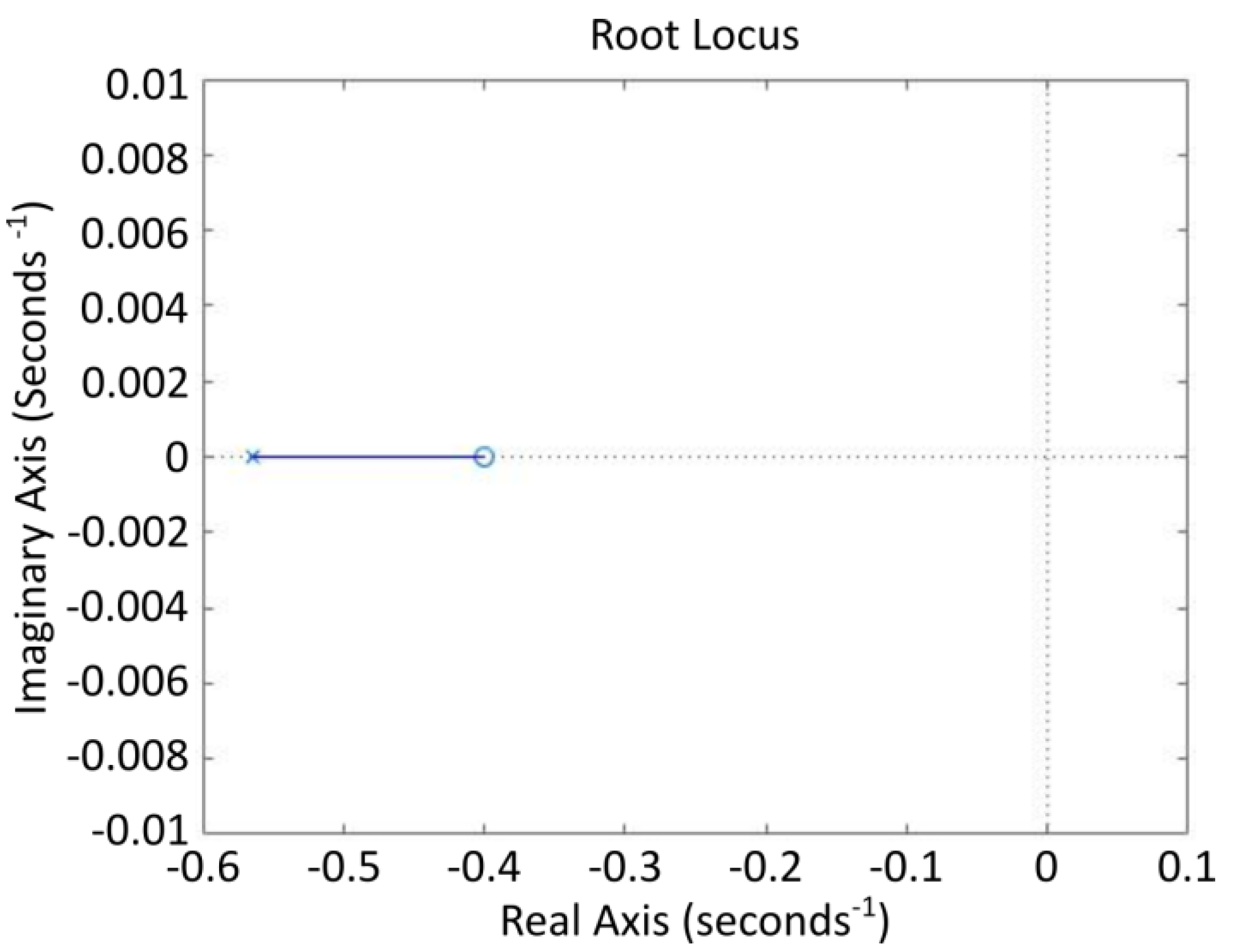
Since the range of the input variable was between [1500 4000], the original gain (G plant) was between [0.1214 0.1526]. The Matlab implementation of the root locus of the transfer function is shown in Figure A1.
Figure A1.
Root locus of the negative feedback loop system transfer function when Kp = 20 and Kd = 50. The system has a singular pole and singular zero.
Figure A1.
Root locus of the negative feedback loop system transfer function when Kp = 20 and Kd = 50. The system has a singular pole and singular zero.

The root locus graph shows that the system had one pole and one zero, which means that we did not need to add any more poles or zeros. As we increased the value of the Kp while keeping the Kd value steady, the pole and the zero moved to the left of the real axis. As we grew the value of the Kd while holding the Kp value steady, the pole and the zero moved to the left along the real axis. If both Kp and Kd were too high compared to 1, then the pole and the zero were nearly identical. The step response of the system is presented in Figure A2.
Figure A2.
Step response of the system when Kp = 2 and Kd = 0.5.

Based on this simulation, the system is stable. To ensure that our system worked correctly, we implemented a PID computer program to our controller and tested through the DAC to the pressure regulator.
References
- Accident Search Results Page | Occupational Safety and Health Administration. Available online: https://www.osha.gov/pls/imis/accidentsearch.search?sic=&sicgroup=&naics=&acc_description=&acc_abstract=&acc_keyword=%22Robot%22&inspnr=&fatal=&officetype=&office=&startmonth=&startday=&startyear=&endmonth=&endday=&endyear=&keyword_list=on&p_start=&p_finish=40&p_sort=&p_desc=DESC&p_direction=Next&p_show=20 (accessed on 9 April 2021).
- Michaelis, J.E.; Siebert-Evenstone, A.; Shaffer, D.W.; Mutlu, B. Collaborative or Simply Uncaged? Understanding Human-Cobot Interactions in Automation. In Proceedings of the 2020 CHI Conference on Human Factors in Computing Systems, Honolulu, HI, USA, 21 April 2020; pp. 1–12. [Google Scholar]
- Lawrence, C. Requiem for Rethink Robotics. Mech. Eng. 2019, 141, 40–45. [Google Scholar] [CrossRef] [Green Version]
- Kim, S.; Laschi, C.; Trimmer, B. Soft Robotics: A Bioinspired Evolution in Robotics. Trends Biotechnol. 2013, 31, 287–294. [Google Scholar] [CrossRef] [PubMed]
- Li, H.; Go, G.; Ko, S.Y.; Park, J.-O.; Park, S. Magnetic Actuated PH-Responsive Hydrogel-Based Soft Micro-Robot for Targeted Drug Delivery. Smart Mater. Struct. 2016, 25, 027001. [Google Scholar] [CrossRef]
- Shepherd, R.F.; Ilievski, F.; Choi, W.; Morin, S.A.; Stokes, A.A.; Mazzeo, A.D.; Chen, X.; Wang, M.; Whitesides, G.M. Multigait Soft Robot. Proc. Natl. Acad. Sci. USA 2011, 108, 20400–20403. [Google Scholar] [CrossRef] [PubMed] [Green Version]
- Majidi, C. Soft Robotics: A Perspective—Current Trends and Prospects for the Future. Soft Robot. 2013, 1, 5–11. [Google Scholar] [CrossRef]
- Wehner, M.; Truby, R.L.; Fitzgerald, D.J.; Mosadegh, B.; Whitesides, G.M.; Lewis, J.A.; Wood, R.J. An Integrated Design and Fabrication Strategy for Entirely Soft, Autonomous Robots. Nature 2016, 536, 451–455. [Google Scholar] [CrossRef]
- Wehner, M.; Tolley, M.T.; Mengüç, Y.; Park, Y.-L.; Mozeika, A.; Ding, Y.; Onal, C.; Shepherd, R.F.; Whitesides, G.M.; Wood, R.J. Pneumatic Energy Sources for Autonomous and Wearable Soft Robotics. Soft Robot. 2014, 1, 263–274. [Google Scholar] [CrossRef] [Green Version]
- Goldfield, E.C.; Park, Y.-L.; Chen, B.-R.; Hsu, W.-H.; Young, D.; Wehner, M.; Kelty-Stephen, D.G.; Stirling, L.; Weinberg, M.; Newman, D. Bio-Inspired Design of Soft Robotic Assistive Devices: The Interface of Physics, Biology, and Behavior. Ecol. Psychol. 2012, 24, 300–327. [Google Scholar] [CrossRef]
- Usevitch, N.S.; Hammond, Z.M.; Schwager, M.; Okamura, A.M.; Hawkes, E.W.; Follmer, S. An Untethered Isoperimetric Soft Robot. Sci. Robot. 2020, 5. [Google Scholar] [CrossRef] [PubMed]
- Sanan, S.; Lynn, P.S.; Griffith, S.T. Pneumatic Torsional Actuators for Inflatable Robots. J. Mech. Robot. 2014, 6, 031003. [Google Scholar] [CrossRef]
- Greer, J.D.; Blumenschein, L.H.; Alterovitz, R.; Hawkes, E.W.; Okamura, A.M. Robust Navigation of a Soft Growing Robot by Exploiting Contact with the Environment. Int. J. Robot. Res. 2020, 39, 1724–1738. [Google Scholar] [CrossRef] [Green Version]
- Teeple, C.B.; Koutros, T.N.; Graule, M.A.; Wood, R.J. Multi-Segment Soft Robotic Fingers Enable Robust Precision Grasping. Int. J. Robot. Res. 2020, 39, 1647–1667. [Google Scholar] [CrossRef]
- Marchese, A.D.; Onal, C.D.; Rus, D. Autonomous Soft Robotic Fish Capable of Escape Maneuvers Using Fluidic Elastomer Actuators. Soft Robot. 2014, 1, 75–87. [Google Scholar] [CrossRef] [PubMed] [Green Version]
- Pfeifer, R.; Lungarella, M.; Iida, F. The Challenges Ahead for Bio-Inspired’soft’robotics. Commun. ACM 2012, 55, 76–87. [Google Scholar] [CrossRef]
- Whitesides, G.M. Soft Robotics. Angew. Chem. Int. Ed. 2018, 57, 4258–4273. [Google Scholar] [CrossRef] [PubMed]
- Nakajima, K.; Hauser, H.; Li, T.; Pfeifer, R. Exploiting the Dynamics of Soft Materials for Machine Learning. Soft Robot. 2018, 5, 339–347. [Google Scholar] [CrossRef] [PubMed] [Green Version]
- Laschi, C.; Cianchetti, M. Soft Robotics: New Perspectives for Robot Bodyware and Control. Front. Bioeng. Biotechnol. 2014, 2, 3. [Google Scholar] [CrossRef] [PubMed] [Green Version]
- Boivin, M.; Milutinović, D.; Wehner, M. Movement Error Based Control for a Firm Touch of a Soft Somatosensitive Actuator. In Proceedings of the 2019 American Control Conference (ACC), Philadelphia, PA, USA, 10–12 July 2019; pp. 7–12. [Google Scholar]
- Koivikko, A.; Raei, E.S.; Sariola, V.; Mosallaei, M.; Mantysalo, M. Soft Actuators with Screen-Printed Curvature Sensors. In Proceedings of the 2017 IEEE SENSORS, Glasgow, UK, 29 October–1 November 2017; pp. 1–3. [Google Scholar]
- Kim, D.H.; Lee, S.W.; Park, H.-S. Sensor Evaluation for Soft Robotic Hand Rehabilitation Devices. In Proceedings of the 2016 6th IEEE International Conference on Biomedical Robotics and Biomechatronics (BioRob), Singapore, 26–29 June 2016; pp. 1220–1223. [Google Scholar]
- Gerboni, G.; Diodato, A.; Ciuti, G.; Cianchetti, M.; Menciassi, A. Feedback Control of Soft Robot Actuators via Commercial Flex Bend Sensors. IEEEASME Trans. Mechatron. 2017, 22, 1881–1888. [Google Scholar] [CrossRef]
- Truby, R.L.; Wehner, M.; Grosskopf, A.K.; Vogt, D.M.; Uzel, S.G.; Wood, R.J.; Lewis, J.A. Soft Somatosensitive Actuators via Embedded 3D Printing. Adv. Mater. 2018, 30, 1706383. [Google Scholar] [CrossRef] [PubMed] [Green Version]
- Vogt, D.; Menguc, Y.; Park, Y.-L.; Wehner, M.; Kramer, R.K.; Majidi, C.; Jentoft, L.P.; Tenzer, Y.; Howe, R.D.; Wood, R.J. Progress in Soft, Flexible, and Stretchable Sensing Systems. In Proceedings of the International Workshop on Research Frontiers in Electronics Skin Technology at ICRA, Karlsruhe, Germany, 6–10 May 2013; Volume 13. [Google Scholar]
- Bauer, A.; Wollherr, D.; Buss, M. Human–Robot Collaboration: A Survey. Int. J. Humanoid Robot. 2008, 5, 47–66. [Google Scholar] [CrossRef]
- Wehner, M. Man to Machine, Applications in Electromyography. EMG Methods Eval. Muscle Nerve Funct. 2012, 29, 427–454. [Google Scholar]
- Jayanthi, N.; Indu, S. Comparison of Image Matching Techniques. Int. J. Latest Trends Eng. Technol. 2016, 7, 396–401. [Google Scholar]
- Morrow, J.; Shin, H.-S.; Phillips-Grafflin, C.; Jang, S.-H.; Torrey, J.; Larkins, R.; Dang, S.; Park, Y.-L.; Berenson, D. Improving Soft Pneumatic Actuator Fingers through Integration of Soft Sensors, Position and Force Control, and Rigid Fingernails. In Proceedings of the 2016 IEEE International Conference on Robotics and Automation (ICRA), Stockholm, Sweden, 16–21 May 2016; pp. 5024–5031. [Google Scholar]
- Nasab, A.M.; Sabzehzar, A.; Tatari, M.; Majidi, C.; Shan, W. A Soft Gripper with Rigidity Tunable Elastomer Strips as Ligaments. Soft Robot. 2017, 4, 411–420. [Google Scholar] [CrossRef] [PubMed]
- Murray, D.; Basu, A. Motion Tracking with an Active Camera. IEEE Trans. Pattern Anal. Mach. Intell. 1994, 16, 449–459. [Google Scholar] [CrossRef] [Green Version]
Figure 1.
Soft finger actuator. (A). Actuator component (green) fabricated between stacked molds (blue, transparent). (B). Two actuator components before bonding. Green and yellow layers can be different material (different moduli) to prescribe actuator performance. Luer-lock needle (blue) inserted for pneumatic operation. (C). Actuator partially inflated instrumented with tracking markers. (D). Markers as tracked by software. (E). Finger position as interpreted by visual servoing system.

Figure 2.
System overview. (A). System diagram of the finger actuator configuration. This configuration is used for uncontrolled, passive impedance control, and visual servoing feedback control approaches. For uncontrolled and passive impedance control approaches, a camera and PC are used for data acquisition only. For the visual servoing feedback control approach, the finger position is captured by the camera and quantized by the image processing algorithm in the PC, which sends a pressure-set point signal via a microcontroller through the digital-to-analog converter to the relieving pressure regulator (black arrows, data); the regulator regulates actuator pressure by adding pressurized air from upstream pneumatic supply or venting to atmosphere (blue lines). (B). A flexed soft finger actuator, controlled by the regulator system shown.

Figure 3.
Motion of an uncontrolled pneumatic finger actuator. (A) Tracking positions of five markers along the length of the actuator during quasi-static inflation and deflation. Origin selected as a stationary point at the base of the actuator. (B) Uncontrolled finger response to sudden application of pneumatic pressure, followed by sudden venting to ambient (square wave). Image shows vertical (Y) displacement of the most distal marker. Here, zero is reported as the steady-state deflated height of the marker. Overshoot during inflation is 12.0% and during deflation is 14.9%. (C) Oscillations of greater than 1% of steady state are seen for five cycles after inflation and seven cycles after deflation, nearly two seconds in each direction.

Figure 4.
Square wave input, two approaches. (A). Pressure and displacement vs. time for approach 1 (Passive impedance). Pressure alternates between high and low setpoints as square wave. Infill and vent line impedances have been tuned to minimize ringing while maximize speed to setpoint. (B). Pressure/displacement curves for approach 2 (Visual servoing feedback control). The system is programmed to alternate the Y-height of the most distal marker between two setpoints.

Figure 5.
Response to perturbation. The actuator can be perturbed and modulate pressure to maintain the position of its most distal marker. (A). Pressure vs. time as the controller attempts to retain the height (Y value) of the distal marker. (B). Change in Y-height (Disturbance) of distal marker due to introduction and removal of external perturbation. Due to the compliant nature of the soft actuator, the distal end of the finger is able to achieve greater curvature and maintain Y-height when perturbed (10–16 s, 23–37 s). When perturbation is removed slowly (16–20 s, 37–41 s), the system is able to recover with little overshoot. When perturbation is removed quickly (56–60 s), the system experiences larger error before recovering (see Supplementary Information Video S2).

Publisher’s Note: MDPI stays neutral with regard to jurisdictional claims in published maps and institutional affiliations. |
© 2021 by the authors. Licensee MDPI, Basel, Switzerland. This article is an open access article distributed under the terms and conditions of the Creative Commons Attribution (CC BY) license (https://creativecommons.org/licenses/by/4.0/).
Share and Cite
MDPI and ACS Style
Li, D.; Dornadula, V.; Lin, K.; Wehner, M. Position Control for Soft Actuators, Next Steps toward Inherently Safe Interaction. Electronics 2021, 10, 1116. https://doi.org/10.3390/electronics10091116
AMA Style
Li D, Dornadula V, Lin K, Wehner M. Position Control for Soft Actuators, Next Steps toward Inherently Safe Interaction. Electronics. 2021; 10(9):1116. https://doi.org/10.3390/electronics10091116
Chicago/Turabian StyleLi, Dongshuo, Vaishnavi Dornadula, Kengyu Lin, and Michael Wehner. 2021. "Position Control for Soft Actuators, Next Steps toward Inherently Safe Interaction" Electronics 10, no. 9: 1116. https://doi.org/10.3390/electronics10091116
Note that from the first issue of 2016, this journal uses article numbers instead of page numbers. See further details here.