
High-Q Slot Resonator Used in Chipless Tag Design


1
School of Navigation, Jimei University, Xiamen 361021, China
2
School of Information Engineering, Jimei University, Xiamen 361021, China
*
Author to whom correspondence should be addressed.
Electronics 2021, 10(9), 1119; https://doi.org/10.3390/electronics10091119
Submission received: 5 April 2021
/
Revised: 30 April 2021
/
Accepted: 5 May 2021
/
Published: 9 May 2021
(This article belongs to the Special Issue Advances in Chipless RFID Technology)
Abstract
:A retransmission chipless tag with multiple U-shaped slot resonators is proposed to cut down the cost of traditional tags with chips. Multiple side-by-side U-shaped slot structures of different lengths are printed on the microstrip line, and the two terminals of the microstrip line are connected correspondingly with two orthogonal ultra-wideband (UWB) transceiver antennas to form the retransmission chipless tag. The U-shaped slot resonator has high Q values and narrow impedance bandwidth. The bandwidth that each resonator adds to the protection bandwidth is 300 MHz. Several 6-bit coding U-shaped slot resonator chipless tags are designed and fabricated for comparison and measurement. Results show that the simulation and the measurement are in agreement. The slot width of the U-shaped slot resonator and the distance between the resonators are reduced, resulting in deepened spectrum notch depth of the resonator. Decreasing the dielectric constant of the substrate or increasing the thickness of the substrate increases the spectrum notch depth of the resonator.
1. Introduction
Radio frequency identification (RFID), a wireless communication technology for noncontact automatic identification and tracking, identifies remote tags by using radio frequency (RF) wave and extracts the encoded data from the backscatter wave. The system is composed of a reader, RFID tags, and a data processing system. The working principle of the RFID system is shown in Figure 1. A continuous wave interrogation signal is transmitted to the tag through the reader antenna. The antenna of the chipped tag receives the interrogation signal and generates an induced current to obtain energy. In this way, the tag is awakened to work. The modulated coded information of the chipped tag is transmitted to the reader with backscatter wave, which decodes the modulated information of the tag. Finally, the encoded data of the tag is obtained by the system [1,2].
RFID systems do not require manual intervention and have the advantages of non-line-of-sight (NLOS) reading and high data capacity. Therefore, chipless tags have the potential to replace barcodes [3,4]. However, the high cost of traditional RFID systems hinders their application in the market for low-value commodities (such as stamps, tickets, and envelopes). The cost of barcodes is very low, about USD $0.005, while the cost of RFID tags is about USD $0.3 [5]. The price of RFID tags is much higher than barcodes, so barcodes still have a greater price advantage. The cost of the entire RFID system depends on the cost of the tag, because the reader has a one-time cost, and there is no need to replace it after it is put to use. The tag needs to be attached to the item and the quantity is huge. The traditional chip tag needs to be made of Silicon chips, the cost of which cannot be further reduced due to indispensable materials and manufacturing processes [6]. Therefore, a chipless tag is proposed. The cost of the chipless tag is mainly determined by the cost of the conductive material constituting its resonant circuit. In the chipless tag, the cost has been greatly reduced due to the removal of the silicon chip of the tag. Moreover, it also has the advantages of the traditional chip tag. However, chipless tags have shortcomings in terms of data capacity and tag size [7].
In recent decades, many researchers have proposed various types of chipless tags, which are divided into two categories: time-domain (TD) [8,9,10,11,12,13], and frequency-domain (FD) chipless tags [14,15,16,17,18,19,20,21,22,23,24,25,26,27,28]
The Ref. [8] proposed a near-field chipless tag system with sequential reading in the time domain. It is realized by multiple linear half-wavelength microstrip resonators which excited in the direction of a vertical straight line. The encoding capacity can reach 100 bits. The density per surface is 4.9 bit/cm2. A series of rectangular patches etching on a dielectric substrate constitute the chipless tag. A pair of rectangular complementary resonators (CSRR) is loaded on a microstrip line to move on the chipless tag printed on the substrate, with rectangular patches of different sizes to generate time-domain codes [9]. The density per surface is 1.15 bit/cm2. However, the moving speed of the chipless tag proposed in the literature [8,9] must be constant. The reader and the tag must be aligned, which is a requirement that is difficult to meet in practical applications.
Chipless tags based on TD also include SAW [10] and transmission delay line chipless tags [11,12,13]. Hartmann et al. [10] have proposed a new modulation method of time overlapped pulse position with simultaneous phase offset modulation. This method has an encoding capacity of up to 256 bits, reaching the encoding capacity of traditional chip tags because the traditional tag-equipped chips have 64-bit, 96-bit, 128-bit and 256-bit RFID standards [29] However, the SAW tag’s nonprintable and high-cost characteristic limits its application in the market. Chipless tags based on the transmission delay line are printable TD tags. The literature [11] has proposed a transmission delay line-based identification (ID) generation circuit, which only realizes four bits of encoding capacity. If the number of encoding bits is increased, the corresponding dimension increases rapidly.
Chipless tags based on the FD are divided into the backscattered [14,15,16,17,18,19] and the retransmitted chipless tags [20,21,22,23,24,25,26,27,28]. The backscattering chipless tag depends on the self-resonance of its multi-resonator to generate spectral characteristics for encoding. The tag does not need a Tx/RX antenna, which is an advantage of its small size and long reading distance. However, a complex algorithm is required to separate the radar cross-section (RCS) signal of the tag before it can be decoded in the actual environment [30,31,32]. The retransmission chipless tag consists of two cross-polarized antennas and a multi-resonator that stores data. The two orthogonally polarized antennas can remarkably decrease the interference between the transmitting and the receiving signals [33]. The system has a low reading error rate and a long reading distance. The tag coding capacity is increased by adding more resonators. The distance between resonators can be adjusted to reduce the coupling effect [34,35,36]. The literature [20,21] first proposed a retransmission chipless tag composed of 6-bit spiral resonators. In order to increase the encoding capacity of the tag, the spiral resonator was increased to 35, the encoding capacity was increased to 35 bits, and the tag size was 88 mm × 65 mm. Although, in order to reduce the size of the tag, the microstrip line was bent and the spiral resonator was placed on both sides of the microstrip line. The tag size was correspondingly increased, and there was a small amount of coupling between the resonators. Retransmissible tags require orthogonal polarization antennas to retransmit information to the orthogonal polarization antennas of the reader. The polarization fields of the reader and the tag must be aligned, otherwise the system sensitivity will be reduced and the error code rate will rise.
It is unrealistic to fully align the orthogonal antennas in practical applications. This situation has promoted the search for chipless tags that are insensitive to polarization [17,18,19]. Current research is based on backscatter chipless tags.
The inherent low isolation between the transmitter and receiver in a chipless tag reader greatly reduces the dynamic range and sensitivity of the reader. The strong excitation signal leaking to the receiver will reduce the sensitivity of the reader to detect weak backscattered signals and reduce the reading range.
This paper has designed a retransmission chipless tag with multiple U-shaped slot bandstop resonators. The U-shaped slot bandstop resonator unit used in the tag has a high Q-value, low coupling effect, high spectrum efficiency, and high encoding capacity. The high isolation of the receiving and the transmitting signals of the tag are due to the orthogonal transceiver antenna. Furthermore, the tag uses transmitting and receiving antennas, resulting in prolonged reading distance.
2. Working Principle
2.1. Working Principle of a Retransmission RFID System Chipless Tag
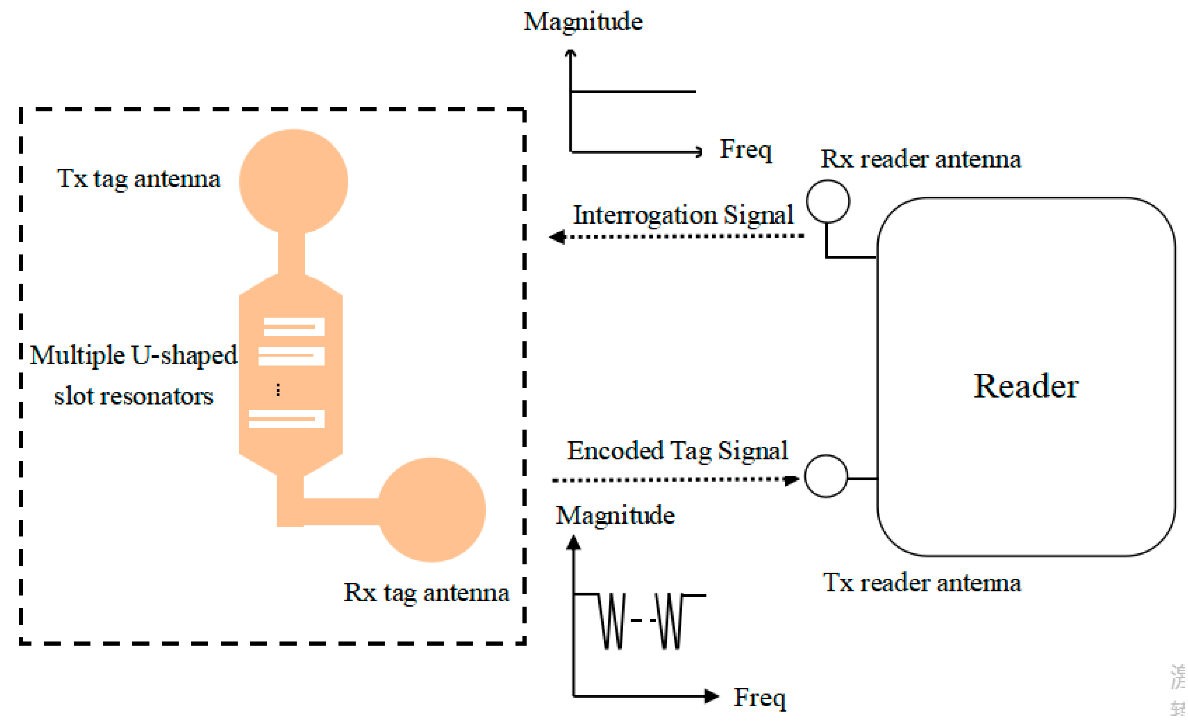
Figure 2 shows the working principle diagram of multiple U-shaped slot resonators with retransmitting chipless tags. First, the reader sends a UWB interrogation signal with a uniform spectrum. Afterward, the receiving antenna of the tag receives the interrogation signal, which is transferred through the resonance circuits to the tag’s transmitting antenna. During the transmission process, the uniformly UWB spectrum structure is changed by the U-shaped slot resonators, and the encoding information on the tag is loaded into the spectrum of the UWB interrogation signal. The UWB signal loaded with encoded information is retransmitted back to the RFID reader by the tag. Then, the data information can be demodulated through the decoding algorithm. The spectral signature of the multiple U-shaped slot resonators has band-stop characteristics at the different resonance frequencies. The resonant frequency point and the data bit are in a 1:1 correspondence (n resonators = n bits), which appears as a notch in the spectrum. When the reader recognizes that the spectrum-characteristic notch exists, the logic state is “1”, and the absence of the spectrum characteristic notch is represented by the logic state of “0”. The polarization characteristics of the reader transmitting antenna and the tag receiving antenna are consistent, and the reader receiving antenna’s polarization characteristic is consistent with the tag transmitting antenna. The transceiver antennas of the reader have orthogonally polarized to each other to maximize the isolation from the continuous interrogation and the encoded modulation signals and avoid mutual interference in the antennas [22]. The polarization characteristics of the tag transceiver antenna are also the same.
According to the Friis transmission formula [37], when the distance between the antennas meets the far-field conditions, and without environmental interference, the power density of the receiving antenna of the RFID system reader is
where PT,reader is the power of the tag-transmitting antenna, Gtag is the gain of the tag-transmitting antenna, and R is the distance between the transmitting and the receiving antennas.
The effective area of the receiving antenna of the RFID system is
The power of the receiving antenna of the RFID system reader is
where Greader is the gain of the reader-receiving antenna, Lp is the power transmission coefficient, and λ is the wavelength.
The Q-value can be calculated by Equation (4)
where B is defined as the −10 dB impedance bandwidth of the U-shaped slot resonator; f is the center frequency of U-shaped slot resonators.
2.2. U-Shaped Slot
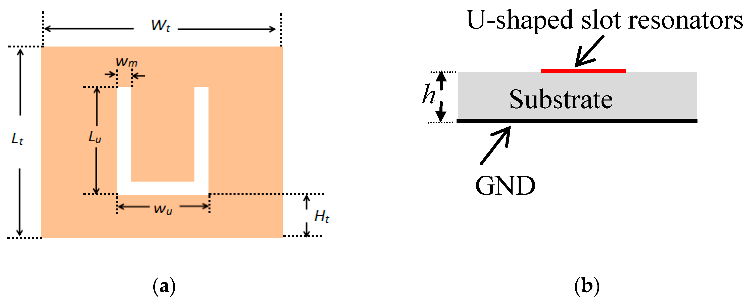
The U-shaped slot is widely used in the patch antenna design [38,39]. The structural parameters of a U-shaped slot of chipless tag are shown in Figure 3, where Lt is the width of the microstrip line, Wt is the length of the microstrip line, and Lu is the length of the U-shaped slot. Wm is the slot width of the U-shaped slot, wu is the length of the bottom side of the U-shaped slot, Ht is the distance from the U-shaped slot in the microstrip line, and h is the thickness of the substrate.
3. Design and Simulation of the Chipless Tag for U-Shaped Slot Resonators
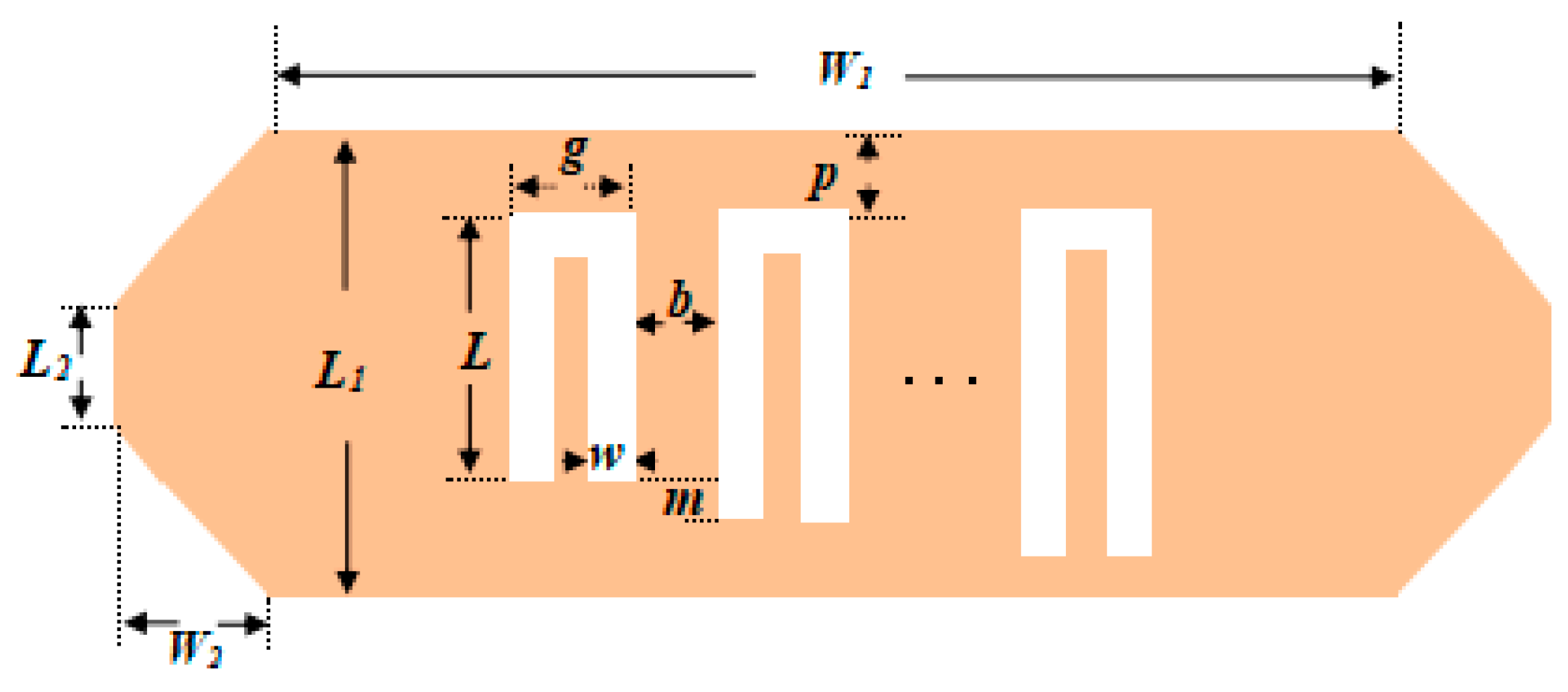
Multiple side-by-side U-shaped slot resonators placed parallel to each other are etched on the microstrip line to form a multi-bit chipless tag, visible in Figure 4, where the L1 is the width of the microstrip line, W1 is the length of the microstrip line, L is the length of the shortest U-shaped slot resonator, and m is the side length difference between adjacent U-shaped slots. w is the slot width of the U-shaped slot resonator, and all U-shaped slot resonators have the same slot width. g is the length of the bottom side of the U-shaped slot resonator and is fixed and consistent with the length of the microstrip line. The distance between adjacent U-shaped slot resonators is b. Different resonance frequencies can be obtained by changing the length of a U-shaped slot resonator. A trapezoidal microstrip is used as a transition belt for impedance matching between the microstrip transmission line and the 50-ohm feeder, which plays the role of a gradual transition to impedance, and the reflection will be suppressed.
U-shaped slot resonators are designed on the F4BM substrate. The relative dielectric constant, loss tangent, and substrate thickness are 2.2, 0.0007, and 1.00 mm, respectively. The High-Frequency Structure Simulator (HFSS) is used for the modeling and the simulation of a single U-shaped slot resonator. Figure 5 shows a schematic of the electric field distribution of a single U-shaped slot resonator. The electric field is strongest near the U-shaped slot, indicating that the U-shaped slot has resonated.
The transmission characteristic curve of the single U-shaped slot resonator S21 is shown in Figure 6. When the side length of the single U-shaped slot resonator is 7 mm, the fundamental frequency of the resonator is 8.28 GHz, and the notch depth of the spectrum characteristic achieves −22 dB. Moreover, the impedance bandwidth B is 0.04 GHz. Q-value is about 207.
Considering that this structure generates second harmonics at 17.67 GHz, the fundamental frequency of the shortest U-shaped slot cannot exceed 17.67 GHz. Otherwise, the second harmonic of the longest slot interferes with the encoded data onto the shortest slot and eventually causes bit errors. Therefore, the available coding frequency band is 8.28 GHz to 17.67 GHz. The bandwidth occupied by a single resonator is 40 MHz. If the guard band of the spectrum-characteristic notches of adjacent resonators is 260 MHz, the 31-bit frequency position code can be formed in the available frequency band, and the largest code states can reach 231.
According to the literature [40], for very thin conductors (that is, thickness→0), the expression of the characteristic impedance Z0 is as follows:
where ɛre is the effective dielectric constant, Ω is the wave impedance in free space, u = L2 / h, and
The accuracy of this expression applies to εr ≤ 128 and 0.01 ≤ u ≤ 10.
From Equation (11), the width L2 of the Z0 = 50 Ω trapezoidal microstrip can be obtained. Due to the limitation of processing accuracy, the size adjustment step length of numerical simulation cannot be lower than the process requirements of chipless tag manufacturing. According to the relevant theoretical formula of the U-shaped slot [38,39], after the HFSS software simulation and design, the structural parameters of the 6-bits U-shaped slot resonator are finally determined in Table 1.
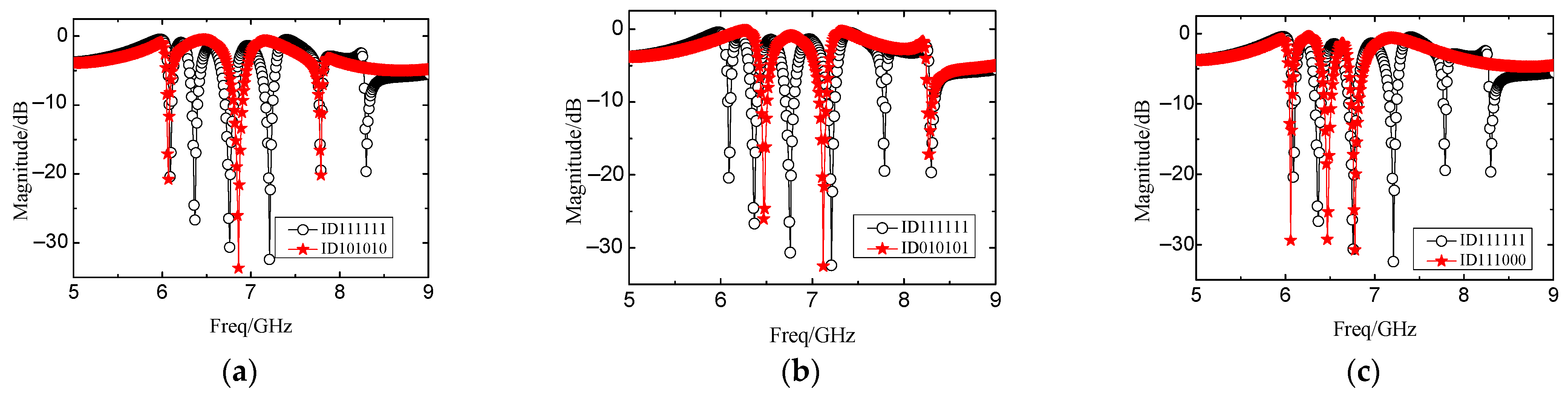
Figure 7 and Figure 8 show the resonance curves of the 4-bits coding tags, namely ID111111, ID111000, ID101010, and ID010101. The ID111111 tag is considered the reference tag. The six resonance spectral notches of the reference tag ID111111 are 6.09, 6.37, 6.76, 7.21, 7.79, and 8.30 GHz, respectively. The notch depth of the spectrum characteristic is between −19 dB and −32 dB. The corresponding spectrum width of each resonator is narrow. The spectrum notch is deep, and the spectrum utilization rate is high.
4. Experimental Results
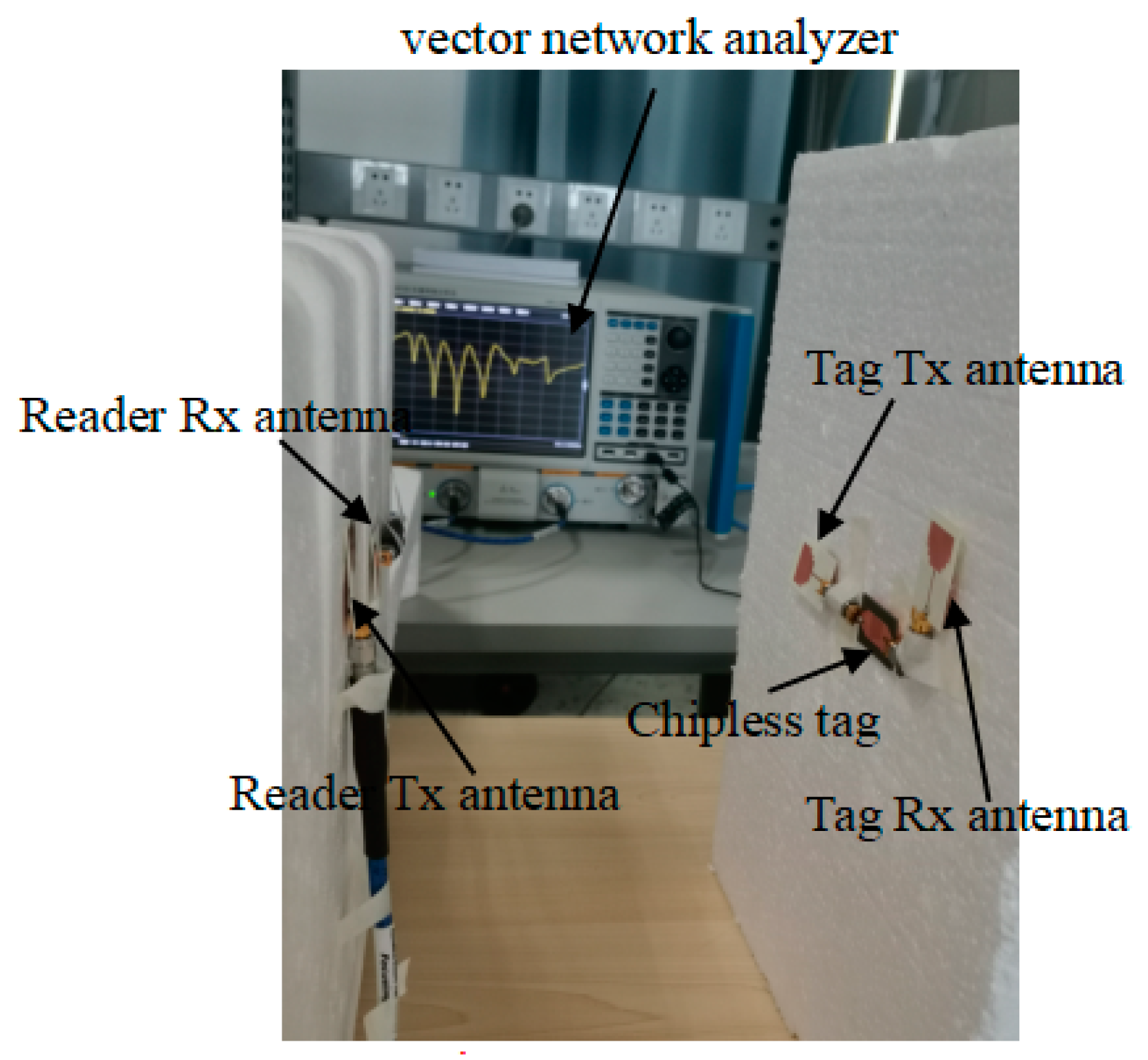
Figure 9 is the test system of a retransmission chipless tag based on multi-state resonators. The experimental setup architecture was composed of a UWB reader, Tx/Rx antennas and a chipless tag. A Ceyear vector network analyzer 3672D was used as an alternative to the UWB reader. The two ports of the network analyzer were, respectively, connected to the L-shaped slot-loaded stepped-impedance UWB antennas [41], which were orthogonal to each other to improve the transceiver isolation of the reader. The tag was connected to two orthogonal L-shaped slot-loaded stepped-impedance UWB antennas through two microwave adapters. In order to prevent the received signal and the transmitted signal of the tag from interfering with each other, the two-sided UWB antennas of the tag were also orthogonal to each other. Both the reader antennas and the tag antennas were fixed on the foam, 10 cm apart. The gain of the L-shaped slot-loaded stepped-impedance UWB antenna was 4 dBi to 8.54 dBi in the range of 2.39 GHz to 13.78 GHz.
The experimental setup architecture was composed of a UWB reader and a chipless tag. The two ports of the network analyzer were, respectively, connected to the UWB antennas, which were orthogonal to each other to improve the transceiver isolation of the reader. The chipless tag needed two orthogonal transceiver antennas; similarly, the chipless reader also needed two orthogonal transceiver antennas which would not affect each other. The polarization characteristics of the transmitting antenna of the reader and the receiving antenna of the tag were the same. The polarization characteristics of the receiving antenna of the reader and the transmitting antenna of the tag were the same. The receiving antenna of the reader received the signal that was transmitting from the tag; however, the transmitting antenna of the reader would not receive any signal from the tag.
In accordance with the simulated U-shaped resonator chipless tag structure, several typical coded chipless tags with a coding capacity of 6 bits were produced, namely ID111111, ID010101, ID101010, ID111000, and the photo is shown in Figure 10. A simulated current vector of the U-shaped slot resonator is shown in Figure 11.
The simulation and the measurement results of the 6-bit U-shaped slot resonators are shown in Figure 12. Figure 12a shows that the six U-shaped slot resonators correspond to six resonance points. The simulation and the measurement results are consistent. A 100 MHz frequency deviation appeared at the 5th resonance point. The value is within the allowable resonator bandwidth, so it does not affect the encoding state of the tag. Figure 12b–d show that, after removing the U-shaped slot, the corresponding simulated and measured resonance points also disappeared, and that the simulation and measurement results are the same. Figure 12 illustrates that the bandwidth of each resonator in the measurement result is broadened compared to that of the simulation result, and the simulation result of the lost arm is larger than the measurement result. The UWB antenna is connected to the resonant circuits by the connector. Although the connector can produce the insertion loss during the measurement, the spectral characteristics of the measured tag can correctly reflect the coding data of the tag, which does not affect the use of the tag.
5. Discussion
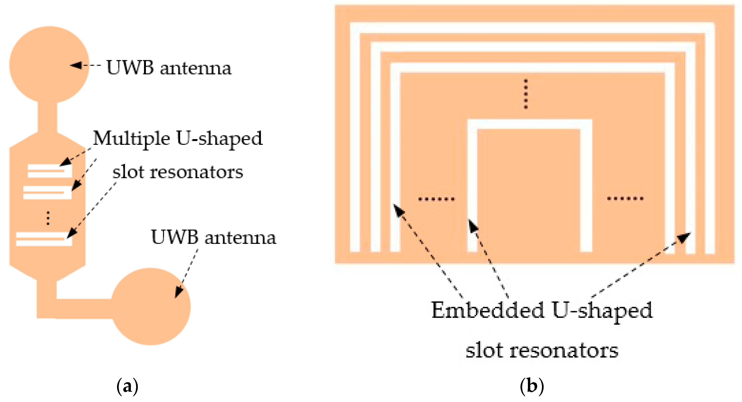
The U-shaped slot resonator is used in retransmission chipless tag RFID systems. It brings a lot of advantages to this design. To compare it to other similar work, Figure 13 shows the schematic diagrams of our design and the other U-shaped slot chipless tag [34]. Our work is shown in Figure 13a. Md Aminul Islam et al. [34] used embedded U-shaped slots based on self-resonance. The electric field must be excited along the direction of the U-shaped slot opening. In our work, the Rx UWB antenna received the interrogation signal and the cascade U-shaped slot resonators changed the structure of the UWB spectrum. Then, the Tx UWB antenna transmitted them to the reader. For our design, the strength of retransmission signal is much greater than the comparison tag in Figure 13b. The coupling effect between the resonators is weak. The chipless tag in our design has high sensitivity, is long in distance, is omnidirectional, etc.
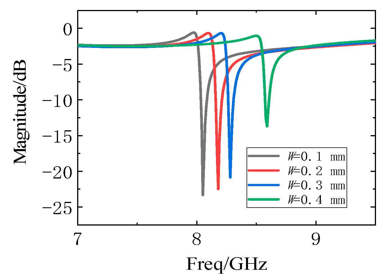
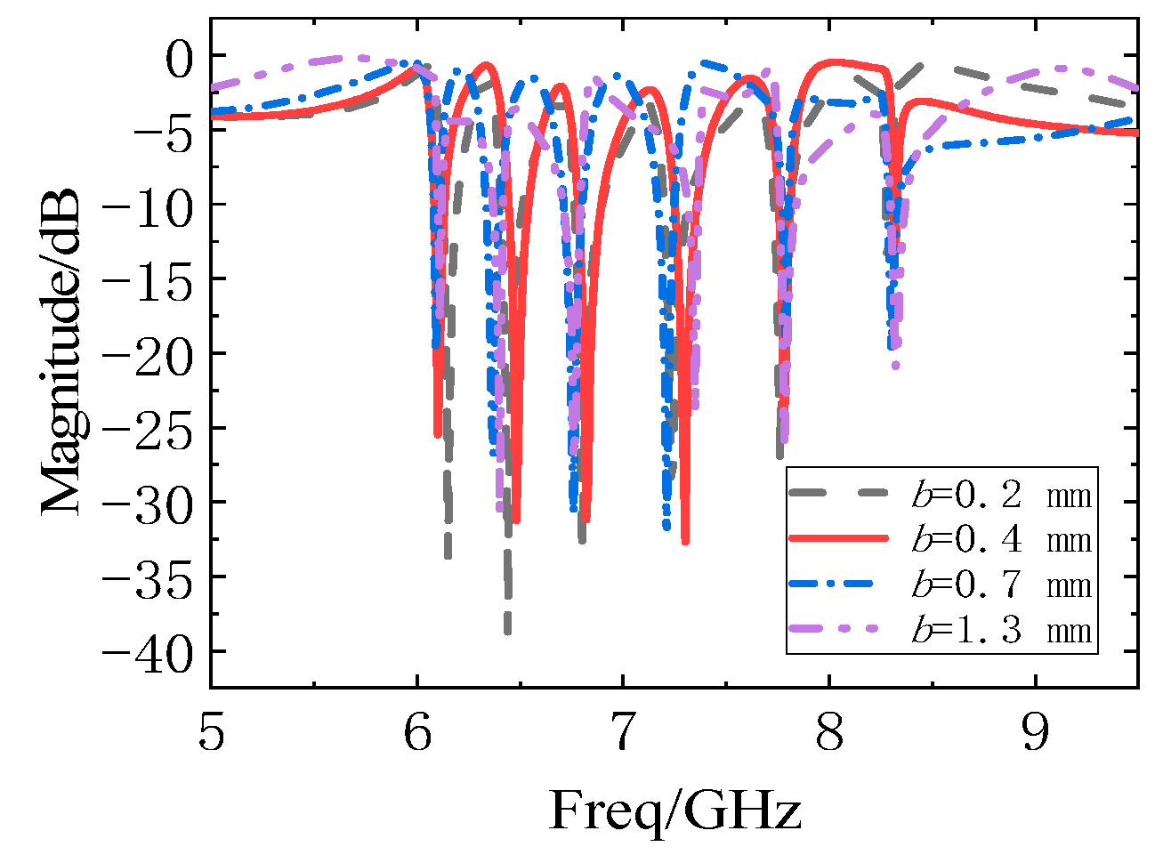
The resonance frequency of a U-shaped slot resonator is determined by the length of the slot and the influence of other parameters, such as the slot width (w) of the U-shaped slot and the distance (b) between the resonators, which are shown in Figure 14 and Figure 15. When the length of the U-shaped slot resonator is 7 mm, the resonance curves corresponding to the change in w from 0.1 mm to 0.7 mm in steps of 0.1 mm is shown in Figure 14. When the slot w changes, the width of the resonance point is unchanged. As the w of the slot narrows, the resonance frequency decreases, and the notch corresponding to the resonance point deepens. The resonance characteristics of b are adjusted to study the coupling effect of U-shaped slot resonators (Figure 15). The b decreases and the notch depth of the resonators deepens, but the resonance frequency is almost unchanged, indicating that U-shaped slot resonators are minimally affected by the coupling effect.
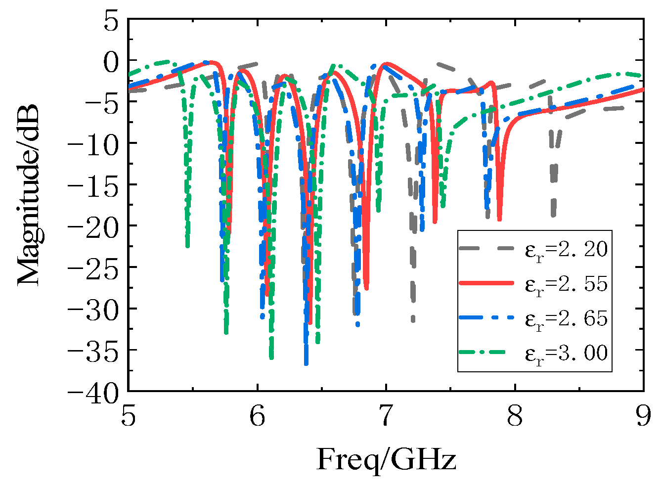
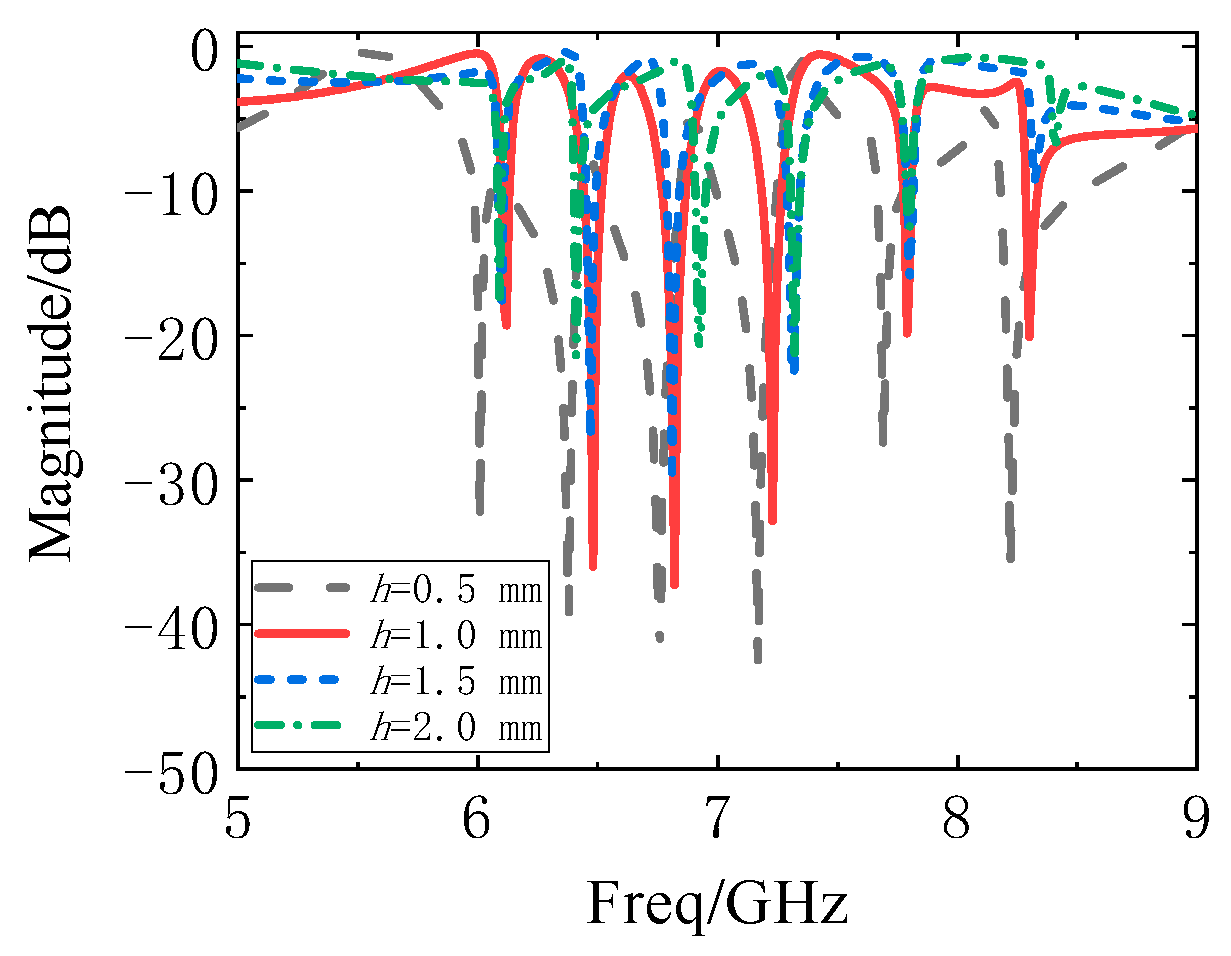
The resonance characteristics of tags with different dielectric constants (Figure 16) and dielectric thicknesses (Figure 17) are studied to directly print the chipless tag of the U-shaped slot resonator structure on materials of different thicknesses, like a barcode. Figure 16 shows that, when the dielectric constant of the medium is 2.2, 2.55, 2.65, and 3.0, the resonance frequency decreases with increasing dielectric constant εr. When the printed materials are different, the frequency position needs to be re-encoded, and the frequency position code of the reference tag needs to be re-encoded. Figure 17 illustrates the tag resonance curve obtained by changing the substrate thickness from 0.5 mm to 2 mm in steps of 0.5 mm. The resonance frequency corresponding to the U-shaped slot resonator changes slightly when the thickness is changed, but the resonance frequency increases as the thickness increases.
Figure 18 and Figure 19 show the resonance curves of the resonator with the longest side length and the resonator with the shortest side length, as the number of resonators constituting the chipless tag is increased to 31 bits. Through HFSS software simulation, it was found that the side length of the U-shaped slot resonator with the shortest side length and the longest side length is 2.9 mm and 11 mm, respectively. The side length difference between adjacent resonators is 0.27 mm. At the same time, the width of all U-shaped slot resonators is the same, at 2.9 mm. The dimension of the 31-bits chipless tag is 113.94 mm × 21.2 mm. The cascades of the U-shaped resonators are arranged side by side. The resonant frequency of the shortest resonator in the 31-bits chipless tag is 13.88 GHz. Meanwhile, the longest resonator corresponds to a resonant frequency of 4.7 GHz.
Table 2 lists the performance comparisons of various types of retransmission chipless tags. The U-shaped slot resonator chipless tags proposed in this paper are simple in design, with high Q-value and small size. The capacity is 1.03 bits/cm2. The spectral capacity is 2.71 bits/GHz. Compared to other retransmission chipless tags, such as ref. [21], the designed 6-bit U-shaped slot resonator has insufficient spectral capacity. However, due to the high Q value of the U-shaped slot resonator, the spectrum utilization rate is high. The substrate size of the 6-bit tag is designed to be 30 × 19.5 mm2. Adding a resonator can increase the encoding capacity of the tag. However, the tag size of the U-shaped slot resonator will not be too large. The tag performance designed in this paper can be expanded.
6. Conclusions
In this paper, a compact U-shaped slot resonator chipless tag based on a retransmission structure is proposed. The resonance unit uses a U-shaped slot resonator with a high Q-value. This type of resonator has a weak mutual coupling effect and is suitable for multi-bit chipless tag design. Given the influence of the second harmonic of the U-shaped slot resonator, this tag can only work in the 8.28–17.67 GHz frequency bands. Finally, 6 bits of U-shaped slot resonators are produced for testing, and results have fully verified the feasibility of this type of chipless tag. Considering that the chipless tag does not need to use any silicon-based circuit or semiconductor device groups, the cost of the tag is low. Moreover, the tag has the same printable characteristics as the barcode, thereby presenting its potential to replace the barcode and be put to wide use in logistics, supermarkets, and other fields.
Author Contributions
These authors contributed equally to this work. Z.M. provided critical feedback, contributed to the research of this project. N.H. conceived the study and the experiments. Z.M. and J.C. carried out the experiments and data analysis. All authors discussed the results and participated in drafting and revising the manuscript. All authors have read and agreed to the published version of the manuscript.
Funding
This research was funded by the Fujian Natural Science Foundation Project, grant number 2019J01718.
Conflicts of Interest
The authors declare no conflict of interest.
References
- Stockman, H. Communication by Means of Reflected Power. Proc. IRE 1948, 36, 1196–1204. [Google Scholar] [CrossRef]
- Nikitin, P.V.; Rao, K.V.S. LabVIEW-Based UHF RFID Tag Test and Measurement System. IEEE Trans. Ind. Electron. 2009, 56, 2374–2381. [Google Scholar] [CrossRef] [Green Version]
- Akbari, A.; Mirshahi, S.; Hashemipour, M. Comparison of RFID system and barcode reader for manufacturing processes. In Proceedings of the 2015 IEEE 28th Canadian Conference on Electrical and Computer Engineering (CCECE), Halifax, NS, Canada, 3–6 May 2015; pp. 502–506. [Google Scholar]
- Preradovic, S.; Karmakar, N.C. Chipless RFID: Bar Code of the Future. IEEE Microw. Mag. 2010, 11, 87–97. [Google Scholar] [CrossRef]
- Harrop, P. The Price-Sensitivity Curve for RFID. Available online: https://www.researchgate.net/publication/294393388_The_price-sensitivity_curve_for_RFID (accessed on 26 July 2020).
- Kaiser, U.; Steinhagen, W. A low-power transponder IC for high-performance identification systems. IEEE J. Solid-State Circuits 1995, 30, 306–310. [Google Scholar] [CrossRef]
- Herrojo, C.; Mata-Contreras, J.; Paredes, F.; Núñez, A.; Ramon, E.; Martín, F. Near-field chipless-RFID system with erasable/programmable 40-bit tags inkjet printed on paper substrates. IEEE Microw. Wirel. Compon. Lett. 2018, 28, 272–274. [Google Scholar] [CrossRef]
- Havlicek, J.; Herrojo, C.; Paredes, F.; Mata-Contreras, J.; Martin, F. Enhancing the Per-Unit-Length Data Density in Near-Field Chipless-RFID Systems with Sequential Bit Reading. IEEE Antennas Wirel. Propag. Lett. 2019, 18, 89–92. [Google Scholar] [CrossRef]
- Paredes, F.; Herrojo, C.; Escudé, R.; Ramon, E.; Martín, F. High Data Density Near-Field Chipless-RFID Tags with Synchronous Reading. IEEE J. Radio Freq. Identif. 2020, 4, 517–524. [Google Scholar] [CrossRef]
- Hartmann, C.S. A global SAW ID Tag with large data capacity. In Proceedings of the IEEE Ultrasonics Symposium, Munich, Germany, 8–11 October 2002; pp. 65–69. [Google Scholar]
- Chamarti, A.; Varahramyan, K. Transmission delay line based ID generation circuit for RFID applications. IEEE Microw. Wirel. Compon. Lett. 2006, 16, 588–590. [Google Scholar] [CrossRef]
- Gupta, S.; Nikfal, B.; Caloz, C. Chipless RFID System Based on Group Delay Engineered Dispersive Delay Structures. IEEE Antennas Wirel. Propag. Lett. 2011, 10, 1366–1368. [Google Scholar] [CrossRef]
- Shao, B.; Chen, Q.; Amin, Y.; David, S.M.; Liu, R.; Zheng, L. An ultra-low-cost RFID tag with 1.67 Gbps data rate by ink-jet printing on paper substrate. In Proceedings of the IEEE Asian Solid-State Circuits Conference, Beijing, China, 8–10 November 2010; pp. 1–4. [Google Scholar]
- EPCglobal Tag Data Standards Version 1.5, ed. Available online: http://www.gs1.org/gsmp/kc/epcglobal/tds/tds15-standard-20100818 (accessed on 26 July 2011).
- Svanda, M.; Havlicek, J.; Machac, J.; Polivka, M. Polarisation independent chipless RFID tag based on circular arrangement of dual-spiral capacitively-loaded dipoles with robust RCS response. IET Microw. Antennas Propag. 2018, 12, 2167–2171. [Google Scholar] [CrossRef] [Green Version]
- Chen, N.; Shen, Y.; Dong, G.; Hu, S. Compact Scalable Modeling of Chipless RFID Tag Based on High-Impedance Surface. IEEE Trans. Electron Devices 2019, 66, 200–206. [Google Scholar] [CrossRef]
- Sharma, V.; Malhotra, S.; Hashmi, M. Slot Resonator Based Novel Orientation Independent Chipless RFID Tag Configurations. IEEE Sens. J. 2019, 19, 5153–5160. [Google Scholar] [CrossRef]
- Babaeian, F.; Karmakar, N. A Cross-Polar Orientation Insensitive Chipless RFID Tag. In Proceedings of the 2019 IEEE International Conference on RFID Technology and Applications, Pisa, Italy, 25–27 September 2019; pp. 116–119. [Google Scholar]
- Vena, A.; Perret, E.; Tedjini, S. High-Capacity Chipless RFID Tag Insensitive to the Polarization. IEEE Trans. Antennas Propag. 2012, 60, 4509–4515. [Google Scholar] [CrossRef]
- Tariq, N.; Riaz, M.A.; Shahid, H.; Khan, M.J.; Khan, M.S.; Amin, Y.; Loo, J.; Tenhunen, H. Orientation Independent Chipless RFID Tag Using Novel Trefoil Resonators. IEEE Access 2019, 7, 122398–122407. [Google Scholar] [CrossRef]
- Preradovic, S.; Balbin, I.; Karmakar, N.C.; Swiegers, G.F. Multiresonator-Based Chipless RFID System for Low-Cost Item Tracking. IEEE Trans. Microw. Theory Tech. 2009, 57, 1411–1419. [Google Scholar] [CrossRef] [Green Version]
- Preradovic, S.; Karmakar, N.C. Design of fully printable planar chipless RFID transponder with 35-bit data capacity. In Proceedings of the 2009 European Microwave Conference (EuMC), Rome, Italy, 29 September–1 October 2009; pp. 13–16. [Google Scholar]
- Preradovic, S.; Roy, S.; Karmakar, N. Fully printable multi-bit chipless RFID transponder on flexible laminate. In Proceedings of the Asia Pacific Microwave Conference, Singapore, 7–10 December 2009; pp. 2371–2374. [Google Scholar]
- Nijas, C.M.; Dinesh, R.; Deepak, U.; Rasheed, A.; Mridula, S.; Vasudevan, K.; Mohanan, P. Chipless RFID Tag Using Multiple Microstrip Open Stub Resonators. IEEE Trans. Antennas Propag. 2012, 60, 4429–4432. [Google Scholar] [CrossRef]
- Ashraf, M.A.; Alshoudokhi, Y.A.; Behairy, H.M.; Alshareef, M.R.; Alshebeili, S.A.; Issa, K.; Fathallah, H. Design and Analysis of Multi-Resonators Loaded Broadband Antipodal Tapered Slot Antenna for Chipless RFID Applications. IEEE Access 2017, 5, 25798–257807. [Google Scholar] [CrossRef]
- Bhuiyan, M.S.; Karmakar, N.C. An efficient coplanar retransmission type chipless RFID tag based on dual-band McSrr. Prog. Electromagn. Res. C 2014, 54, 133–141. [Google Scholar] [CrossRef] [Green Version]
- Preradovic, S.; Karmakar, N.C. Design of Chipless RFID Tag for Operation on Flexible Laminates. IEEE Antennas Wirel. Propag. Lett. 2010, 9, 207–210. [Google Scholar] [CrossRef]
- Sharma, V.; Hashmi, M. Chipless RFID tag based on open-loop resonator. In Proceedings of the Proc. IEEE Asia-Pacific Microw. Conf. (APMC), Kuala Lumpur, Malaysia, 13–16 November 2017; pp. 543–546. [Google Scholar]
- Weng, Y.F.; Cheung, S.W.; Yuk, T.I.; Liu, L. Design of Chipless UWB RFID System Using A CPW Multi-Resonator. IEEE Antennas Propag. Mag. 2013, 55, 13–31. [Google Scholar] [CrossRef] [Green Version]
- Rance, O.; Siragusa, R.; Lemaitre-Auger, P.; Perret, E. Toward RCS magnitude level coding for chipless RFID. IEEE Trans. Microw. Theory Tech. 2016, 64, 2315–2325. [Google Scholar] [CrossRef]
- Marindra, A.M.J.; Tian, G.Y. Chipless RFID sensor tag for metal crack detection and characterization. IEEE Trans. Microw. Theory Tech. 2018, 66, 2452–2462. [Google Scholar] [CrossRef]
- Bibile, M.A.; Karmakar, N.C. Moving Chipless RFID Tag Detection Using Adaptive Wavelet-Based Detection Algorithm. IEEE Trans. Antennas Propag. 2018, 66, 2752–2760. [Google Scholar] [CrossRef]
- Zhang, Y.J.; Gao, R.X.; He, Y.; Tong, M.S. Effective Design of Microstrip-Line Chipless RFID Tags Based on Filter Theory. IEEE Trans. Antennas Propag. 2018, 67, 1428–1436. [Google Scholar] [CrossRef]
- Islam, M.A.; Karmakar, N.C. A Novel Compact Printable Dual-Polarized Chipless RFID System. IEEE Trans. Microw. Theory Tech. 2012, 60, 2142–2151. [Google Scholar] [CrossRef]
- Abdulkawi, W.M.; Sheta, A.A. Design of Chipless RFID Tag Based on Stepped Impedance Resonator for IoT Applications. In Proceedings of the International Conference on Innovation and Intelligence for Informatics, Computing, and Technologies (3ICT), Sakhier, Bahrai, 18–20 November 2018; pp. 1–4. [Google Scholar]
- Abdulkawi, W.M.; Sheta, A.-F.A. Four-State Coupled Line Resonator for Chipless RFID Tags Application. Electronics 2019, 8, 581. [Google Scholar] [CrossRef] [Green Version]
- Rao, K.V.S.; Nikitin, P.V.; Lam, S.F. Antenna design for UHF RFID tags: A review and a practical application. IEEE Trans. Antennas Propag. 2005, 53, 3870–3876. [Google Scholar] [CrossRef]
- Weigand, S.; Huff, G.H.; Pan, K.H.; Bernhard, J.T. Analysis and design of broad-band single-layer rectangular U-slot microstrip patch antennas. IEEE Trans. Antennas Propag. 2003, 51, 457–468. [Google Scholar] [CrossRef]
- Liu, S.; Qi, S.S.; Wu, W.; Fang, D.G. Single-Layer Single-Patch Four-Band Asymmetrical U-Slot Patch Antenna. IEEE Trans. Antennas Propag. 2014, 62, 4895–4899. [Google Scholar] [CrossRef]
- Hammerstad, E.O.; Jensen, O. Accurate models for microstrip computer-aided design. In Proceedings of the 1980 IEEE MTT-S International Microwave Symposium Digest, Washington, DC, USA, 28–30 May 1980; pp. 407–409. [Google Scholar]
- Ma, Z.H.; Jiang, Y.F. L-shaped Slot-loaded stepped-impedance microstrip structure UWB antenna. Micromachines 2020, 11, 828. [Google Scholar] [CrossRef] [PubMed]
Figure 1.
Working principle of the RFID system.

Figure 2.
Working principle diagram of multiple U-shaped slot resonator chipless tags.

Figure 3.
Structure of U-shaped resonators chipless tag: (a) Top view; (b) Side view.

Figure 4.
Electric field distribution of a single U-shaped slot resonator.

Figure 5.
Electric field distribution of a single U-shaped slot resonator.

Figure 6.
Spectrum curve of a single U-shaped slot resonator.

Figure 7.
Simulation of the resonance curves of the 6 bits U-shaped slot resonator chipless tags with a short-circuit logic state of “0”: (a) ID111111 and ID101010; (b) ID111111 and ID010101;(c) ID111111 and ID111000.
Figure 7.
Simulation of the resonance curves of the 6 bits U-shaped slot resonator chipless tags with a short-circuit logic state of “0”: (a) ID111111 and ID101010; (b) ID111111 and ID010101;(c) ID111111 and ID111000.

Figure 8.
The simulation removed the resonance curves of the 6-bits U-shaped slot resonator chipless tags with a logic state of “0”: (a) ID111111 and ID101010; (b) ID111111 and ID010101;(c) ID111111 and ID111000.
Figure 8.
The simulation removed the resonance curves of the 6-bits U-shaped slot resonator chipless tags with a logic state of “0”: (a) ID111111 and ID101010; (b) ID111111 and ID010101;(c) ID111111 and ID111000.

Figure 9.
Test system.

Figure 10.
Picture of U-shaped slot resonator chipless tags: (a) ID111111; (b) ID101010; (c) ID 010101; (d) ID 111000.
Figure 10.
Picture of U-shaped slot resonator chipless tags: (a) ID111111; (b) ID101010; (c) ID 010101; (d) ID 111000.

Figure 11.
Current vector diagram of U-shaped slot resonator: (a) ID111111; (b) ID101010; (c) ID010101; (d) ID111000.
Figure 11.
Current vector diagram of U-shaped slot resonator: (a) ID111111; (b) ID101010; (c) ID010101; (d) ID111000.

Figure 12.
Simulation and measurement results of U-shaped slot resonator chipless tags: (a) ID111111; (b) ID101010; (c) ID010101; (d) ID111000.
Figure 12.
Simulation and measurement results of U-shaped slot resonator chipless tags: (a) ID111111; (b) ID101010; (c) ID010101; (d) ID111000.


Figure 13.
(a) Schematic of the designed tag based on the retransmission chipless tag; (b) the structure proposed by Islam which used embedded U-shaped slots based on self-resonance.
Figure 13.
(a) Schematic of the designed tag based on the retransmission chipless tag; (b) the structure proposed by Islam which used embedded U-shaped slots based on self-resonance.

Figure 14.
Resonance curves of U-shaped slot resonators with different slot widths.

Figure 15.
Resonance curves when the resonator spacing b is changed.

Figure 16.
Resonance curves of U-shaped slot resonator with different dielectric constants.

Figure 17.
Resonance curves of U-shaped slot resonator with different substrate thickness.

Figure 18.
The maximum resonators of the 31-bit retransmitted chipless tag.

Figure 19.
The minimum resonators of the 31-bit retransmitted chipless tag.


Table 1.
The 6-bits U-shaped slot resonator structural parameters values (unit: mm).
| L1 | W1 | L2 | W2 | L | w | g | b | m | p |
|---|---|---|---|---|---|---|---|---|---|
| 10.5 | 16.7 | 3.06 | 6.62 | 7 | 0.3 | 0.9 | 0.7 | 0.5 | 0.5 |
Table 2.
Comparison of different types of retransmitted chipless tags.
| Resonator Type | Frequency Band (GHz) | Q-Value | Capacity (bits/cm2) | Spectral Capacity (bits/GHz) | Size (mm × mm) |
|---|---|---|---|---|---|
| Spiral [21] | 3–7 | - | 0.61 | 8.75 | 88 × 65 |
| Open stubs [23] | 1.9–4.5 | 8 | 0.17 | 3.08 | 80 × 60 |
| Open stubs [24] | 4–9 | 13 | 0.24 | 3.2 | 110 × 60 |
| Microstrip coupled spiral [25] | 5–10.7 | - | 0.09 | 1.05 | 107 × 65 |
| Modified complementary split ring [26] | 6.8–11.2 | - | 0.07 | 1.82 | 140 × 80 |
| Open loop [27] | 3–6 | 30 | 0.25 | 2.67 | 85 × 38 |
| CPW [28] | 3.3–5.5 | 11 | 0.09 | 3.64 | 154 × 55 |
| U-shaped slot (Proposed) | 6.09–8.30 | 207 | 1.03 | 2.71 | 30 × 19.5 |
Publisher’s Note: MDPI stays neutral with regard to jurisdictional claims in published maps and institutional affiliations. |
© 2021 by the authors. Licensee MDPI, Basel, Switzerland. This article is an open access article distributed under the terms and conditions of the Creative Commons Attribution (CC BY) license (https://creativecommons.org/licenses/by/4.0/).
Share and Cite
MDPI and ACS Style
Huang, N.; Chen, J.; Ma, Z. High-Q Slot Resonator Used in Chipless Tag Design. Electronics 2021, 10, 1119. https://doi.org/10.3390/electronics10091119
AMA Style
Huang N, Chen J, Ma Z. High-Q Slot Resonator Used in Chipless Tag Design. Electronics. 2021; 10(9):1119. https://doi.org/10.3390/electronics10091119
Chicago/Turabian StyleHuang, Nengyu, Jiaxiang Chen, and Zhonghua Ma. 2021. "High-Q Slot Resonator Used in Chipless Tag Design" Electronics 10, no. 9: 1119. https://doi.org/10.3390/electronics10091119
Note that from the first issue of 2016, this journal uses article numbers instead of page numbers. See further details here.