


Abstract
In this research work, a simple homemade cubic phantom was designed to validate the Image-Guided Radiotherapy (IGRT) set up and verified with the help of tungsten fiducial markers (size 2–3 mm) inserted into the cubic phantom. Phantom made up of Styrofoam, was scanned with the help of 16 slice Toshiba CT scanner where each slice was of 1 mm thickness and HU level set to −1000. A radio-opaque contrast medium was rubbed on the phantom to visualize the scanner images. Once the iso-center had been marked on a phantom with the help of in-room positioning laser and the fields (RT-LAT and AP) were applied on the contoured body of the phantom in Varian's ARIA-11 Eclipse dosimeter software, the same position of the phantom was reproduced on Varian's Linear Accelerator DHX. Known shifts of 3.0 to 30.0 mm from the marked iso-center were applied on the phantom by moving the couch in all six directions one by one. On each applied couch shift, an x-ray image of the phantom was acquired with the help of an MV portal imager of Linac in AP and RT-LAT direction. This image was superimposed with a reference image of phantom and shift accuracy calculated by ARIA-11 software was noted down. It turned out that irrespective of the position of the phantom on the couch, the calculated corrected shift and deviation from reference position was always between ± 1–2 mm which is the required accuracy for IGRT according to International Atomic Energy Agency (IAEA). This process was repeated 40 times and each time, the corrected shift came out to be ± 1–2 mm. We can conclude that our system is safe and accurate enough to perfectly position the actual patient for IGRT.
Export citation and abstract BibTeX RIS
1. Introduction
Cancer has become a life-threatening disease throughout the globe and the associated death toll has been raised annually. Reports published by the world health organization (WHO) identified that over nine million people have died in 185 countries from cancer and this number can reach up to thirteen million in the next two decades. There is utmost need to design a novel, reliable and potent strategy for early diagnosis and therapy of cancer to decrease the mortality rate. The traditional treatment techniques for cancer are chemotherapy, surgery, brachytherapy, and radiotherapy [1, 2]. Radiotherapy is considered a versatile technique useful for the treatment of cancer in sophisticated areas of the body where surgery and chemotherapy are not possible to do such as Head and Neck cancer, brain tumor, and leukemia. On the other hand, a wide range of tumors including prostate cancer, breast carcinoma, small cell lung cancer (SCLC), ovarian cancer, and many more can be treated using surgery and chemotherapy along with radiotherapy side by side [3]. A variety of imaging techniques can be utilized for treatment using radiotherapies such as Computed tomography (CT) scan, three-dimensional-Conformal Radiotherapy (3D-CRT), Intensity Modulated Radiotherapy (IMRT), Image-guided Radiotherapy (IGRT), Rapid Arc or VMAT and Cyberknife and GammaKnife [4–6].
Among them, IGRT is assumed to be a more reliable and efficient conformal approach in achieving precise treatment delivery for moveable organs. In this technique, nontoxic metallic radio-opaque fiducial markers are inserted into the tumor before accurately localize the radiation dose delivery into targeted tumor tissue. With the help of fiducial markers which can be visualized via x-ray imaging, oncologists can preferentially locate the site of the tumor, control the interfraction motion of the tumor as well as can effectively deliver the targeted dose to planning tumor volume (PTV) [7, 8]. With the advancements in technology, today, it is possible to see the soft tissues and bony landmarks simultaneously in patients. The benefits associated with IGRT are that it can be used with 3D-CRT, IMRT, and/or proton therapy as hyphenated techniques because of better dose distribution capabilities into the tumor. IGRT has also been observed to increase the dose conformity across PTV while sparing the normal tissues and has potential applications for moveable organs whose position cannot be reproduced identically on regular basis. There are two types of IGRT imaging modalities, one is a 3D-CT scan while the other one is a 4D-CT scan which could be used for localization of tumors using kV imaging and MV imaging techniques [9, 10].
3D printed hollow cubes and/or virtual cubic phantoms (instead of commercially available phantoms) having fiducial marker can also better serve as inputs into the EPID-MV couch to stimulate the imaging artifacts at different gantry angles [11, 12]. Moreover, EPID-MV imaging rather than kV imaging uses comparatively higher patient doses (does not mean that no extra dose can cause side effects) to yield higher quality images. While the imaging doses from the kV portal and kV-CBCT imaging scans utilize less dose than the conventional MV portal imaging strategy [13]. On the other hand, the MV imaging system is considered to be superior to kV imaging in terms of the use of identical geometry for treatment and provides more accurate geometrical information. Furthermore, the MV imaging IGRT system is truly no hitting, no seeing, more suitable, and much more cost-effective than kV imaging counterparts [14, 15].
Literature published in the last two decades highlights the benefits and advancements in the field of IGRT in comparison with other imaging modalities. Which shed light on the importance of this fruitful technique for the effective treatment of cancer most notably prostate, breast, and gastrointestinal cancer [16–18]. To implement the IGRT clinically, it is worth noting to first evaluate the validity of the software and system being used for detection. In this study, we have used Varian's multi-energy linear accelerator DHX along with ARIA-11 software. This tells us about the interfraction movement before targeted dose delivery. Our first goal was to validate the precision and accuracy of the software. A homemade phantom made up of Styrofoam (extruded polystyrene) was used to validate the system and known shifts were performed to achieve the second goal. A nontoxic metallic fiducial marker was inserted into the Styrofoam and required images were acquired using CT-scan. Finally, the results were analyzed with the help of online review software for potential real-time implementation of IGRT clinically.
2. Materials and methods
The materials and techniques used in this study include Varian's linear accelerator (Linac) DHX; fiducial markers (tungsten), Styrofoam phantom, TOSHIBA 16 slice CT scanner, and Eclipse software.
2.1. Varian's linear accelerator (Linac) DHX
Varian's Linac DHX equipped with RF linear wavelength system to accelerate the charged particles from electron gun and oscillator (Klystron or Magnetron) to generate high-frequency RF electromagnetic waves (6.0 MV x-rays) on which electrons are superimposed. These high-speed surfing electrons are either directly used to treat patients with superficial tumors or made strike to high atomic number metallic anode, usually tungsten, to produce high energy x-rays to treat deep-seated tumors [19]. The next component is Klystron which is not a microwave generator but rather it is a microwave oscillator or amplifier. It amplifies the low-energy microwaves generated by the oscillator with the help of an electron bencher cavity which produces high-frequency RF waves to generate up to 6.0 MV x-rays [20]. Another part of the linear accelerator is Gantry from which x-rays come out after passing through various hardware assemblies to make sure that x-ray beam quality is under clinical standards and it can rotate in 360-degree orientation around the patient. Another part is the treatment couch, a flat table consisting of carbon fiber material for insignificant beam attenuation upon which the patients are positioned. It can move in six directions i.e. Superior, Inferior, Left, Right, Up, Down. The next one is the electronic portal imaging device (EPID) which is an array of solid-state radiation detectors with a size of 30 × 40 cm2, 512 × 384 pixels and can detect small objects up to 0.5 mm diameter. The EPID of Varian's Linac DHX used in this study is of MV portal vision and can give optimal imaging results.
2.2. Fiducial markers
Fiducial markers are used to precisely determine the position of moveable organs with an acceptable deviation from the standard position which is around 5.0 mm in length. The fiducial markers should be non-toxic to the human body; hence, the choice of a fiducial marker is of prime importance. We used metallic beads of tungsten having a size of 1 × 5 mm in this study, as our main purpose is to focus the six directional position verification and observation and detection of expected errors. To implement the IGRT clinically, fiducial markers of gold with size 2–5 mm (CIVCO radiotherapy) are of particular value as gold is nontoxic to the human body and can be safely inserted inside the tumor tissue (prostate and lungs) for position verification [21].
2.3. Styrofoam phantom
It is a square shape phantom made up of extruded polystyrene material (15 cm3 dimension) in which the fiducial markers were inserted. The metallic beads were placed on the surface of the phantom for marking purposes. After the CT scan, positioning lasers were marked on the phantom so that the same position can be reproduced on the treatment couch.
2.4. CT scanner equipped eclipse software
TOSHIBA 16 slice CT scanner was used for scanning of Styrofoam phantom to determine the depth and location of the inserted fiducial marker. The thickness of each slice varies from 3–5 mm depending on the type of organ to be scanned. It gives a three-dimensional view of the scanned body in the frontal, sagittal, and transversal planes. It took approximately 1.0 min to scan the whole body. Eclipse software (Varian Medical System version ARIA 11) equipped with a CT scanner was used to match the fiducial markers with their reference image position with the help of EPID. An eclipse is an integrated tool to automatically fix the setup errors which was our primary focus in this study to validate the manual auto-correction of this tool before implementing it for clinical use.
2.5. Styrofoam phantom scanning
To establish the experimental setup, firstly the three metallic beads of tungsten were inserted into the homemade Styrofoam phantom, and then it was positioned on the couch of the CT scanner in room positioning lasers. The laser's position was marked on the surface of the phantom using a black marker and preceded for scanning into TOSHIBA 16 slice CT scanner. As the metallic beads are radio-opaque, the radio-opaque contrast in the form of liquid was applied on the surface of Styrofoam. As the Styrofoam density is equivalent to air so without this it was not visible in images of the CT scanner.
2.6. Contouring, positioning, and shifting of styrofoam phantom
To evaluate the accuracy and validity of Eclipse software for IGRT, contouring, positioning, and shifting of Styrofoam phantom were operated. Once the scan was completed, we draw the body of the Styrofoam phantom in the eclipse software. It was assigned a unique identification number and system mark the position of inserted metallic beads as a reference position in three dimensions (along x, y, and z-axis). Next, we reproduced the position of the Styrofoam phantom followed by repositioning it on the couch of Linac DHX with the help of the same in-room laser assembly as it was set up in the scanner room. It was to make sure that the position of the inserted metallic beads was at the same coordinates as it was during the time of scanning. Furthermore, shifting was performed at different millimeter margins in all six directions of the couch one by one to evaluate the position of the Styrofoam phantom and the data was collected for each time. After getting the port film through EPID, the system told the deviation of tungsten metallic beads from the original position by comparing the difference in iso-center position.
3. Results
3.1. Scanning of styrofoam phantom using a linear accelerator
The homemade Styrofoam phantom containing three tungsten metallic beads was placed on the treatment couch table (figure 1(a)) and these high-energy x-rays were falling on them. The scanning of the phantom (serves as a patient) was done by using the EPID detector of MV portal vision which generates a corresponding electrical signal or pixels. After receiving the attenuated beam, a combination of these pixels make images on 16 slice CT scanner. According to the image, the position was marked on the phantom with the help of a marker as presented in figure 1(b) black squared area. Each slice thickness was 1.0 mm and the metallic beads can be easily visualized in sliced images (frontal, transversal and sagittal views) as the beads are radio-opaque as shown in figure 1(c). Once the scans of the phantom were completed, we draw the body of the phantom using eclipse software and a unique number was assigned to it for use as a reference image as presented by Green Square in figure 1(c). The images of three tungsten metallic beads also presented in the same figure as white (left) and black (right) dots and position was marked along with x, y, and z coordinates.
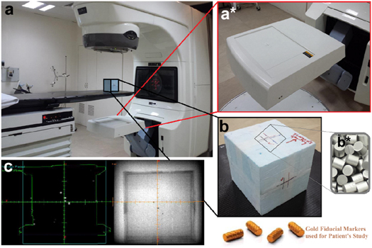
Figure 1. (a) Shows the Varian's Linear Accelerator DHX CT scanner and homemade Styrofoam phantom placed on the treatment couch for positioning using in-room positioning lasers, (a*) shows the zoom image of an electronic portal imaging device (EPID) of MV portal vision. (b) Represents the zoom image of scanned and marked homemade Styrofoam phantom upper face towards Gantry of the linear accelerator through which x-rays comes out and strikes with tungsten metallic beads (b*) fixed into the phantom. (c) Shows the black and white sliced images of tungsten metallic beads after scanning from Eclipse software as reference position along x, y, and z-axis.
Download figure:
Standard image High-resolution image3.2. Positioning, contouring, and shifting of styrofoam phantom
Next to validate the system's accuracy and to evaluate the deviation in the position of metallic beads, the position of the phantom was reproduced using the same in-room laser assembly. Source to Surface Distance (SSD) was noted to be 92.0 cm in Anterior-Posterior (AP) position and 92.5 cm in Right-Lateral (RT-LAT) position with a frame field size of 20 × 20 cm2. Further, the shifts of 5–30 mm with an increment of 5.0 mm were applied on the phantom in all six directions (Superior, Inferior, Left, Right, Up and Down) of the couch with Longitudinal (Lng) 88.5 cm, Lateral (Lat) 0.9 cm and Vertical (Vert) 7.5 cm as well as collimator were adjusted to zero Gantry set at 0 and 270-degree orientation and EPID energy of 6.0 MV was applied. After applying the shifts, the difference was calculated by subtracting the corrected position from the current position of the phantom to observe the deviation as summarized in table 1. It was observed that the system was unable to detect the shifts in Lat position at Gantry = 270 while only shifts can be detected when Gantry = 0. The maximum deviation of 1–2 mm was observed after applying random shifts to the phantom in combination with various positions including AP and RT-LAT as shown in figures 2(a), (c), respectively). The deviation from the actual position after the correction was also monitored by blending and correcting the AP and RT-LAT images as shown in figure 2(b), (d), respectively). The deviation error was fortunately below the accepted error range for IGRT (i.e. 3.0 mm). This small deviation is because of artifacts produced when images were taken through MV portal imager as low energy offers weak absorption of photons into the body, providing blurred images in output as presented in figure 3.
Table 1. The absolute shifts were observed after applying the various shifts and the difference was calculated by subtracting the corrected position from the current position of the phantom.
| Standard Deviations | ||||||||
|---|---|---|---|---|---|---|---|---|
| Gantry = 0 | Gantry = 270 | |||||||
| Shifts | Lng sup | Lng inf | Rt lat | Lt lat | Vert up | Vert down | Lng sup | Lng inf |
| (mm) | (mm) | (mm) | (mm) | (mm) | (mm) | (mm) | (mm) | (mm) |
| 3 | 0.0 | 0.0 | 1.0 | 0.0 | 1.0 | 0.0 | 0.0 | 0.0 |
| 5 | 0.0 | 0.0 | 1.0 | 1.0 | 0.0 | 1.0 | 1.0 | 0.0 |
| 10 | 0.0 | 1.0 | 1.0 | 0.0 | 0.0 | 0.0 | −1.0 | −1.0 |
| 15 | 0.0 | −1.0 | 0.0 | −1.0 | 1.0 | 0.0 | 0.0 | 0.0 |
| 20 | 1.0 | 0.0 | −1.0 | 0.0 | 0.0 | 1.0 | 1.0 | −1.0 |
| 25 | 0.0 | 0.0 | 1.0 | 0.0 | 0.0 | 0.0 | 0.0 | 0.0 |
| 30 | 0.0 | 0.0 | 0.0 | 1.0 | 0.0 | 0.0 | 1.0 | 0.0 |
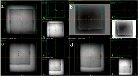
Figure 2. Images were acquired using Eclipse software at various positions including (a) shows images at AP shift position, (b) images taken after blending and correcting AP shift images. On contrary, (c) image was acquired at RT-LAT shift position, meanwhile; (d) represents an image taken after blending and correcting RT-LAT shift position.
Download figure:
Standard image High-resolution image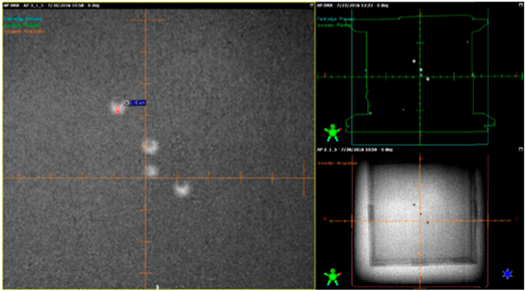
Figure 3. The image artifact was acquired via MV portal vision imager, the blurred image was observed because of weak absorption photons.
Download figure:
Standard image High-resolution image
4. Discussion
All this process of IGRT, before implementation on patients clinically, takes approximately 10 to 20 min which is a very quick way for end-to-end IGRT validation and evaluation. This process includes a CT scan of the IGRT phantom, transferring the images from DICOM to Eclipse, contouring the body, field placement, transferring the plan from Eclipse to linear accelerator [17]. Place an x-ray sensitive cassette under the treatment area of the phantom so that the x-ray beam when interacting with soft tissues or bones of the patient after attenuation makes images on the cassette. Complete attenuation of the beam gives white and no attenuation gives black images, while the rest of the image is formed by the combination of black and white colors. For high-risk patients, IGRT associates with improved biochemical tumor imaging as well as a lower rate of non-specific toxicity as compared to high dose through non-IGRT technique (or IMRT) [22]. In the current study, the maximum positional error was 2.0 mm which was observed relatively small and under permitted range when lateral images were blended. This is due to the artifacts that EPID-MV portal imager of linear accelerator can be easily visualized using transition metal-based fiducial markers with size ≥ 0.75 mm in diameter. As much as the size of the marker will be larger, there are more image artifacts. Smaller-sized fiducial markers can be visualized in kV imaging but with streak artifacts [23, 24]. The reason behind this is the absorption ability of x-rays as low energy x-rays have more absorption probability than those of high energy. The data of different random shifts applied to the phantom shows that irrespective of the position of the phantom on the couch, the chance of error remains within the accepted limit (less than 3.0 mm) for IGRT.
5. Conclusion
The benefits associated with IGRT are strictly lying within the concept of irradiating the PTV with a higher dose than usually prescribed. Since IGRT can efficiently reduce side effects towards critical untargeted organs than any other technique. Our homemade IGRT phantom provides a cost-effective, time-saving, and efficient way for end-to-end IGRT geometrical positional accuracy before treatment delivery. We have successfully tested the positional accuracy of the IGRT phantom by deliberately applying random shifts in all six directions of the coach and found that dose could be delivered with fewer chances of error i.e. between 1–2 mm differences. According to International Atomic Energy Agency (IAEA), the planned dose delivered to the patients in case of IMRT should be within ± 3.0 mm accuracy. After evaluating the results gathered from shifts in combinational positions in AP-LAT and RT-LAT direction simultaneously, the accuracy was observed to be within the tolerance deviation irrespective of the position of the phantom on the couch table which is in good accordance with the IGRT standards. So, based on outcomes obtained, we can suggest that oncologists could be prescribed the higher dose to the tumor site using Eclipse software coupled with the IGRT technique because of higher accurate chances of dose delivery.
Acknowledgments
The authors are cordially thankful to the Chairperson of Shaukat Khanum Memorial Cancer Hospital & Research Centre (SKMCH&RC) Lahore for providing imaging facility and the Chairperson of the Department of Physics for providing necessary materials.
Data availability statement
All data that support the findings of this study are included within the article (and any supplementary files).
Conflict of interest
The authors declare no competing conflict of interest in any case.
Funding
The authors did not receive any kind of funding from any institution or research funding agency to carry out this research work, data assimilation, or publication of the article.