
Long-Term Marine Environment Exposure Effect on Butt-Welded Shipbuilding Steel


.JPG)

1
Marine Engineering Department, Faculty of Maritime Studies, University of Rijeka, Studentska 2, 51000 Rijeka, Croatia
2
Center for Marine Technologies, Faculty of Maritime Studies, University of Rijeka, M. Baraca 19, 51000 Rijeka, Croatia
3
Department of Engineering Mechanics, Faculty of Engineering, University of Rijeka, Vukovarska 58, 51000 Rijeka, Croatia
4
3. Maj Shipyard, Liburnijska 3, 51000 Rijeka, Croatia
*
Author to whom correspondence should be addressed.
J. Mar. Sci. Eng. 2021, 9(5), 491; https://doi.org/10.3390/jmse9050491
Submission received: 9 April 2021
/
Revised: 28 April 2021
/
Accepted: 29 April 2021
/
Published: 1 May 2021
(This article belongs to the Special Issue Ship Structures)
Abstract
:Extreme environments, such as marine environments, have negative impacts on welded steel structures, causing corrosion, reduced structural integrity and, consequently, failures. That is why it is necessary to perform an experimental research sea exposure effect on such structures and materials. Research presented in this paper deals with the mechanical behavior of butt-welded specimens made of AH36 shipbuilding steel when they are exposed to a natural marine environment (water, seawater, sea splash) for prolonged periods (3, 6, 12, 24, and 36 months). The usual approach to such research is to perform accelerated tests in a simulated laboratory environment. Here, relative mass change due to corrosion over time is given along with calculated corrosion rates. Corroded surfaces of specimens were inspected using optical and scanning electron microscopy and comparison, based on the numbers and dimensions of the corrosion pits (diameter and depth) in the observed area. As a result, it can be concluded that exposure between 3 and 6 months shows significant influence on mass loss of specimens. Further, sea splash generally has the most negative impact on corrosion rate due to the combined chemical and mechanical degradation of material. Pit density is the highest at the base metal area of the specimen. The diameters of the corrosion pits grow over the time of exposure as the pits coalesce and join. Pit depths are generally greatest in the heat affected zone area of the specimen.
1. Introduction
Structural integrity of marine steel structures can be greatly reduced by corrosive environments in which they are set. Corrosion can be caused by outer (e.g., water, seawater, sea atmosphere, tides) or inner factors (e.g., ballast water, fuel oil, aggressive cargo) [1,2]. Consequently, loss of structural integrity can lead to failure of steel structures. Marine propulsion systems are generally susceptible to corrosion, leading to a series of possible mechanical failures [3], which is why it is important to gain insight into their fracture behaviors, even if it is the case of marine shaft steels or marine exhaust steels with improved corrosion resistance [4,5]. Damage of masts on the training vessel was caused by deficient welds at the foundation of the masts [6] that accumulated water, enabled corrosion, and reduced the integrity of the structure. A cargo ship [7] sunk due to corrosive influence of the cargo where leaking acid accelerated corrosion of the floor panels, leading to failure. A numerical study showed that corrosion defects in pipelines significantly reduce failure pressure, leading to pipe bursts [8]. Finite element analysis revealed that a barge midship section can decrease for more than a third compared to its initial measure, due to corrosion [9].
Pitting corrosion can be considered one of the most damaging forms of corrosion. Small holes, or pits, are caused by corrosive medium that attacks limited areas on the surface of metal. Stochastic nature of pit distribution poses a threat to the integrity of corroded steel structures. Thus, characterization and quantification of size and distribution of pits is necessary to estimate the structural integrity loss. Different techniques, such as 3D profile measurement [10], X-ray tomography [11], scanning electron microscopy [12] or white light interferometry [13] can be used for such task. As for the effects of pitting corrosion on the marine structures, a recent experimental study revealed that surface machining considerable affects corrosion resistance of steel in seawater environments, even provoking stress-corrosion cracking that has origins in corrosion pits [14]. Further, a study on pitting corrosion resistance of the austenitic stainless steel welded joint revealed that the weld zone is the most critical for pit initiation [15]. Moreover, localized pitting occurs in marine steel-reinforced concrete structures at air-voids in concrete-steel interfaces, provoking further corrosion [16]. In regards to corrosion of steel reinforcement in concrete, a comprehensive model referencing field and laboratory observations, built into the bi-modal solution, was developed [17]. Moreover, a comprehensive study with the aim of developing an advanced technique to predict time-dependent damage caused by the corrosion of marine structures was developed with a corrosion depth formulating as a function of time [18], and a technique applied to determine damage of the ship ballast tank [19].
When dealing with steel welded joints exposed to a corrosive environment, the problem of hydrogen embrittlement should be considered. It was found that cathodic protection can lead to hydrogen embrittlement and that the welds are especially endangered [20]. Moreover, there is a challenge in overcoming indirect environmental effects on the quality of welded joints, in regards to the influence of the storage environment on welding consumables [21].
Additionally, when trying to resolve a problem of corrosion propagation over time, several authors proposed different models of time-variant or time-dependent corrosion wastage models. Just by chronologically selecting the efforts made in the last two decades, a mathematical model that provides statistical characteristics of corrosion wastage as a function of time [22] can be emphasized. Further, a corrosion wastage model was proposed based on a standard non-linear time dependent corrosion model modified by the effects of the different environmental factors contained in the crude oil tank atmosphere [23] or marine atmosphere [24]. As the statistical scatter of corrosion wastage is usually wide, and the reliability of the model relies on it, a model with a formulated Weibull function was developed to account that matter [25]. A similar approach was used to propose a time-dependent pit depth corrosion model for sub-sea gas pipelines [26]. Application of a time-dependent corrosion analysis was used to assess the corrosion impact on automotive structures [27] as they are also prone to corrosion damage and failures [28]. As for the corrosion wastage models for steel bars in concrete, effort was made to develop a model that considers the effects of longitudinal cracking on the chloride and oxygen diffusion [29] or integrate chemo–physical–mechanical, and electrochemical, modeling techniques in an integrated framework [30].
Regarding previously performed studies of the marine environment’s effect on shipbuilding steel corrosion, most of the research was performed in laboratory settings simulating real environments [31] in an accelerated manner [10]. Obviously, there is a lack of long-term experiments in the natural environment [32] focused on the steel corrosion effects. The results of usual laboratory experiments that are performed under controlled conditions and in an accelerated manner prove useful, but they may not relate adequately to the natural environment when investigating corrosion mechanisms [33].
Questions from previous findings served as motivation for the research presented here. The goal of this research was to investigate the prolonged influences of different types of marine environments on butt-welded AH36 steel. Results can be subsequently used in the material selection stage of the structural design process.
2. Materials and Methods
AH36 steel butt-welded specimens were exposed to a real marine environment (water, seawater, sea splash) for prolonged periods (3, 6, 12, 24, and 36 months) in order to determine the influence of these factors on corrosive behavior of such materials. Once extracted, relative mass change of specimens due to corrosion over time was measured. Results are presented in correlation to period of exposure and the type of environment. Moreover, corrosion rates were calculated. Specimen surfaces were inspected using optical and scanning electron microscopy and profilometry. Comparison, based on the numbers and dimensions of corrosion pits in the observed area, is given for specimens exposed to different environments and for different locations on specimens (base metal, heat affected zone, weld metal).
2.1. Material
The presented research was performed on AH36 shipbuilding steel. It is a low-alloy high-strength steel under ASTM A131 standard and a common choice for building large commercial ships, bulk carriers, ferries, and marine and offshore structures, such as pipelines, power plants, port facilities, and oil platforms in general [34]. Minimum yield strength of AH36 should be 355 MPa, while ultimate tensile strength should be in the 490–620 MPa range at room temperature. The most conventional welding methods can be used on AH36 as it has excellent weldability [35].
2.2. Specimen Preparation and Marine Environment Exposure
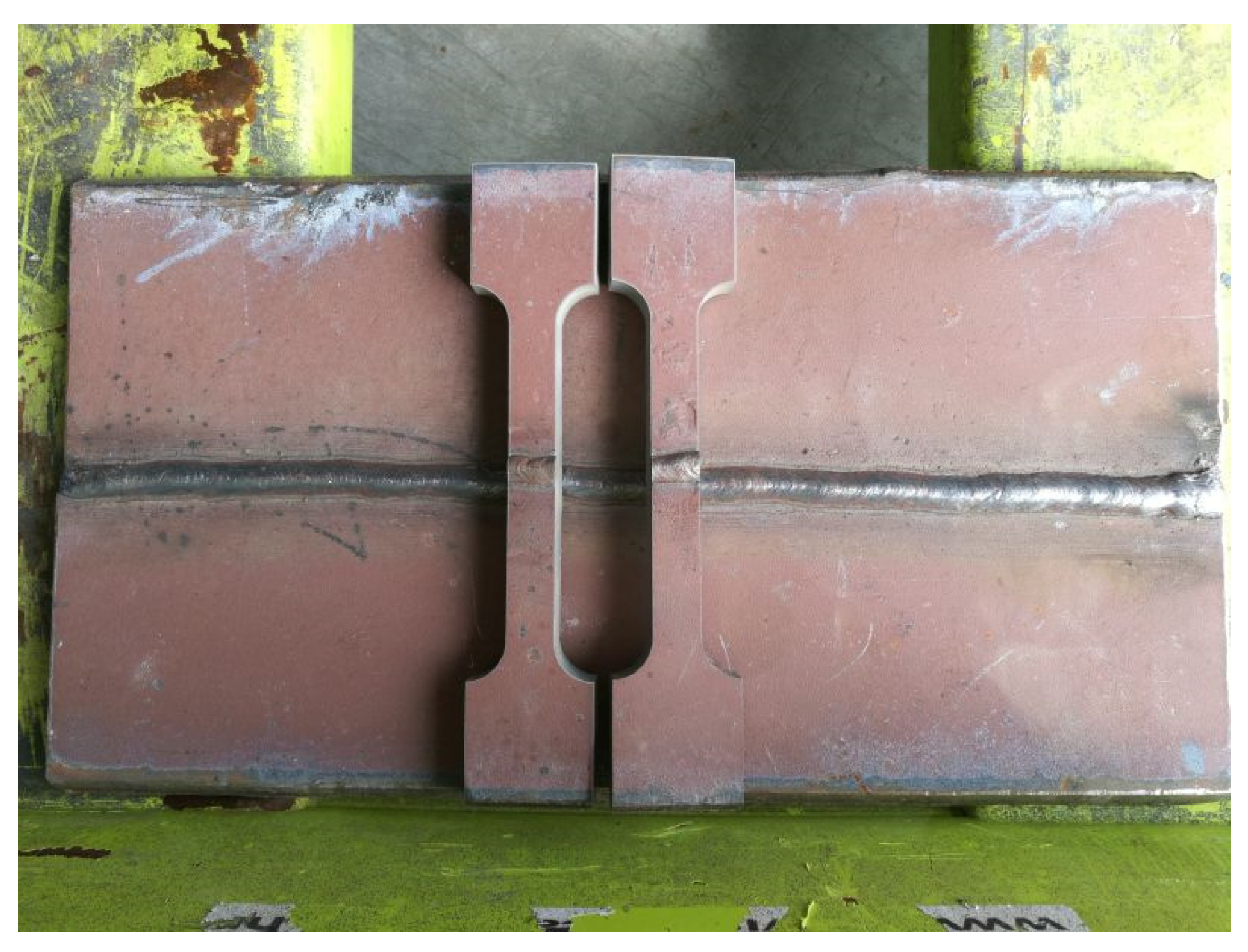
In order to prepare specimens for the experiment, AH36 plates of 12 mm thickness were first machined into 320 × 110 mm rectangular weld blanks, with one side prepared for a single V-groove welded joint. Two blanks were welded with complete joint penetration using the metal active gas (MAG) 136 welding technique. Other details regarding the welding process were: 1.2 mm diameter of welding wire AWS 5.20: E71T-1C; C1 (100% CO2) shielding gas; 15–18 L/min flow rate; Lincoln DC 400, LF 37 welding machine; vertical up welding position; 4 passes; 140–150 A, 21–22 V root parameters, 190–200 A, 24–25 V finish parameters. Butt-welded specimens were cut out parallel to the rolling direction of the plates using water jet technology, Figure 1.
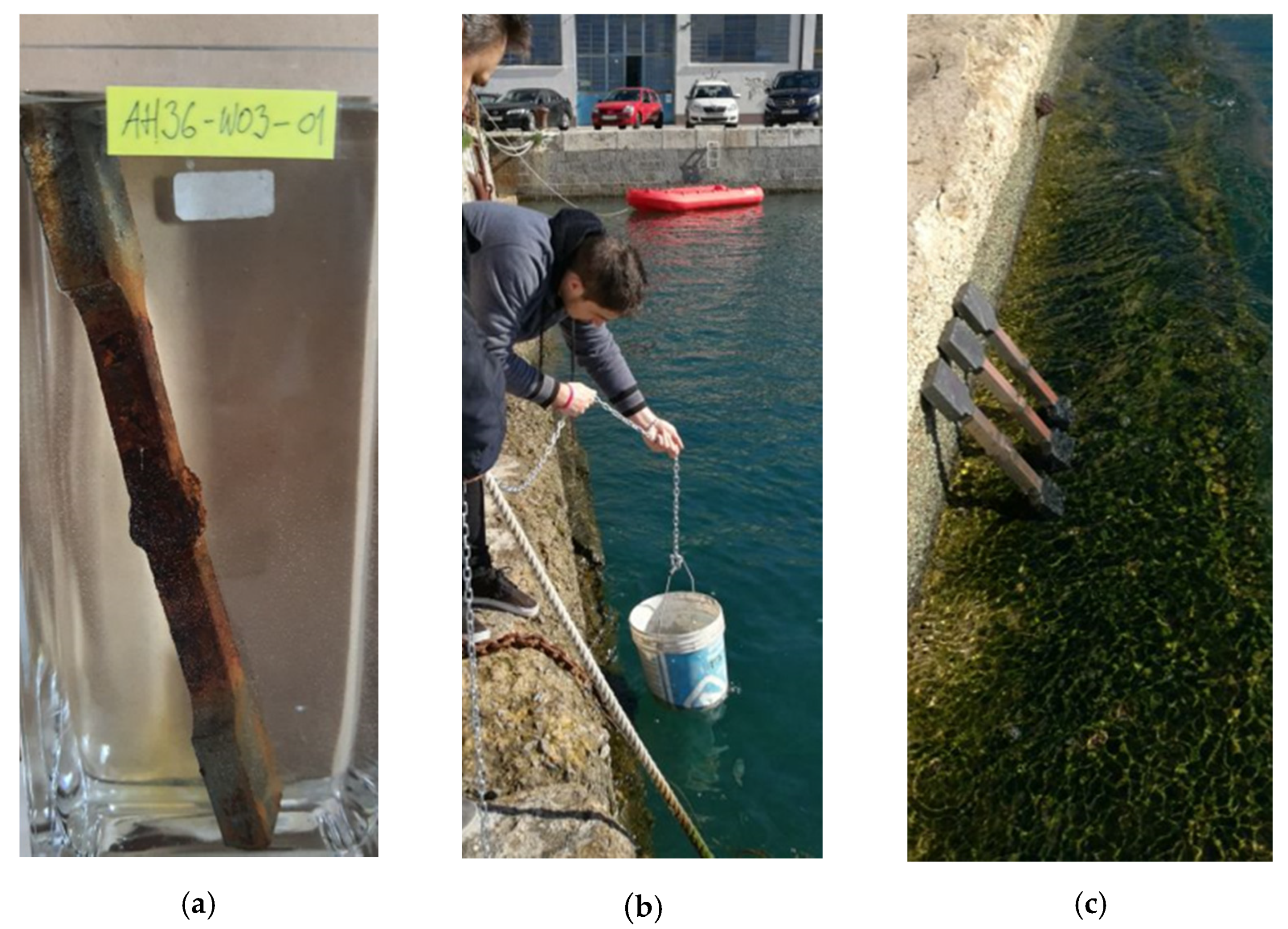
Specimens were exposed to three different types of the environment, Figure 2:
- Tap water in laboratory;
- Seawater, 10 m below sea surface, location: the northern Adriatic, in front of the city of Rijeka in Croatia;
- Sea splash, same geographical location, but with specimens at the sea surface exposed to daily change of tides and splashing of waves.
Specimens were divided into 12 groups, each group containing five specimens, giving a total of 60 specimens. A control group of specimens was kept at room atmosphere. Groups of specimens were exposed to a corrosive environment for 3, 6, 12, 24, and 36 months.
Tap water at room temperature was changed daily to ensure that specimens were in contact with fresh water. Specimens exposed in the sea were affected by changes of sea temperature, salinity, and pH value. At the location of the experiment, sea temperature varied between 10 °C and 14 °C annually, salinity changed between 37.8 and 38.3‰, while the pH value was between 8.22 and 8.29 [37]. After being exposed for 3, 6, 12, 24, and 36 months, the specimens were retrieved from the corrosive environment. Corrosion products were removed from the surface mechanically with a soft brush in running water; specimens were washed with distilled water and dried at room temperature. The procedure was chosen in order to not remove the base material, just corrosion products, but several other procedures can also be applied [38].
2.3. Testing Procedures
Identical digital balance Ohaus 3000 was used before and after the exposure to weigh the specimens in order to determine mass loss.
An 11 MP resolution Sony digital camera was used to obtain digital macro images to investigate localized corrosion on the surface. An area of 200 mm2 (10 mm × 20 mm) was selected on the images to measure the number of corrosion points with ImageJ digital image processing software.
Changes in surface morphology caused by localized corrosion were detected by Olympus SZX10 stereo optical microscope. Moreover, the diameter of corrosion pits was measured this way. Pit depth was measured by analogue Somet pit gauge with 0.01 mm precision. Morphology of the corroded was studied using scanning electron microscope (SEM) FEI Quanta 250.
3. Results
3.1. Mass Loss
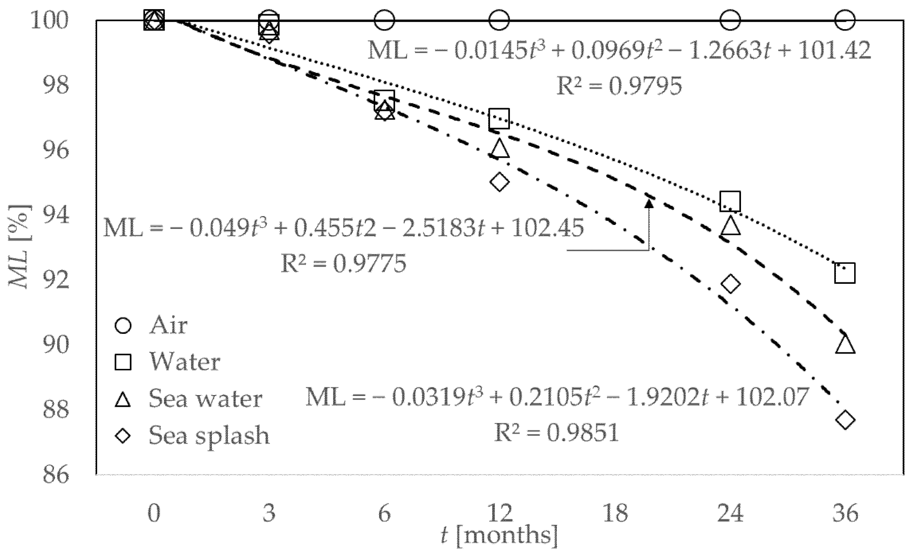
Based on measured values before and after the exposure, the average percentage of mass loss for a group of specimens exposed to different environments was calculated and put in relation to exposure time; Figure 3. Along with measured data, dependency of the average mass loss percentage on the exposure time is represented by approximation curves connecting the experimental values. Additionally, coefficient of determination R2 is displayed.
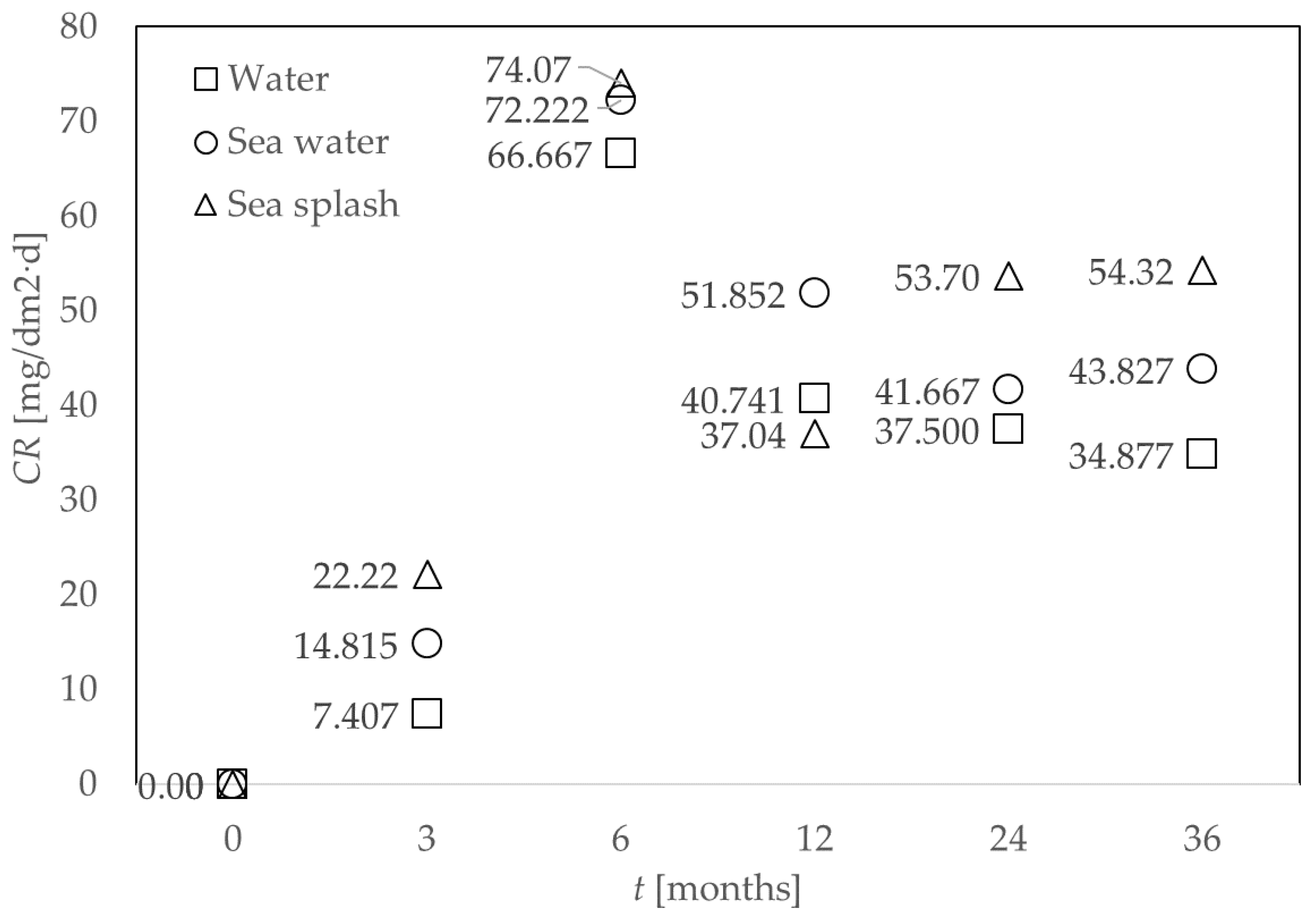
Average corrosion rate CR is calculated according to Equation (2) [39] and given in Figure 4:
where constant K = 2.4 × 10⁶·D, material density D = 7.8 kg/cm3, W = measured mass loss [g], A = specimen area [cm2], T = time of exposure [h]. Corrosion rate describes the material wastage caused by corrosion and it can help in assessing the remaining operational life of material under the influence of the corrosive environment.
3.2. Pit Density and Dimensions
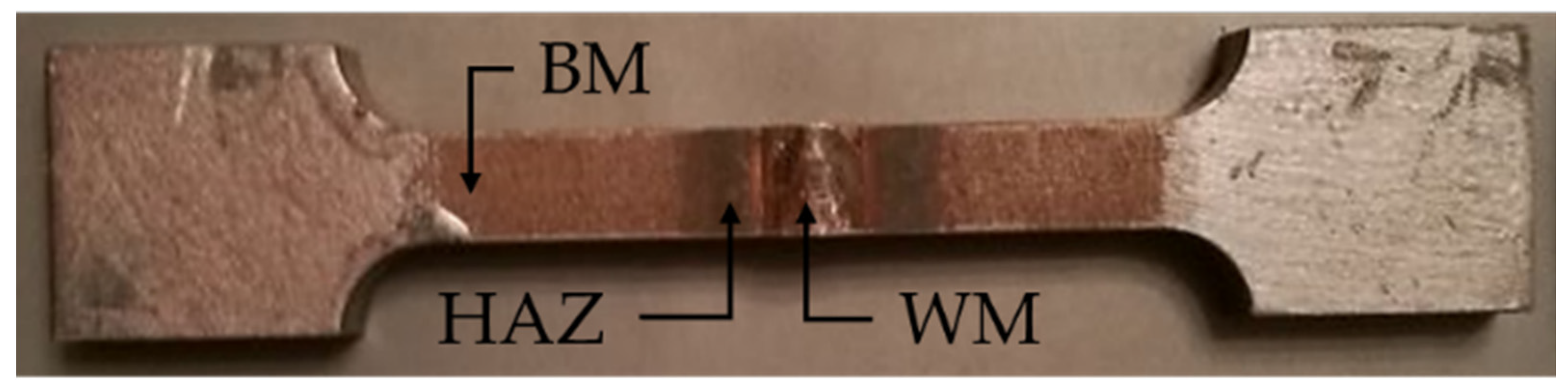
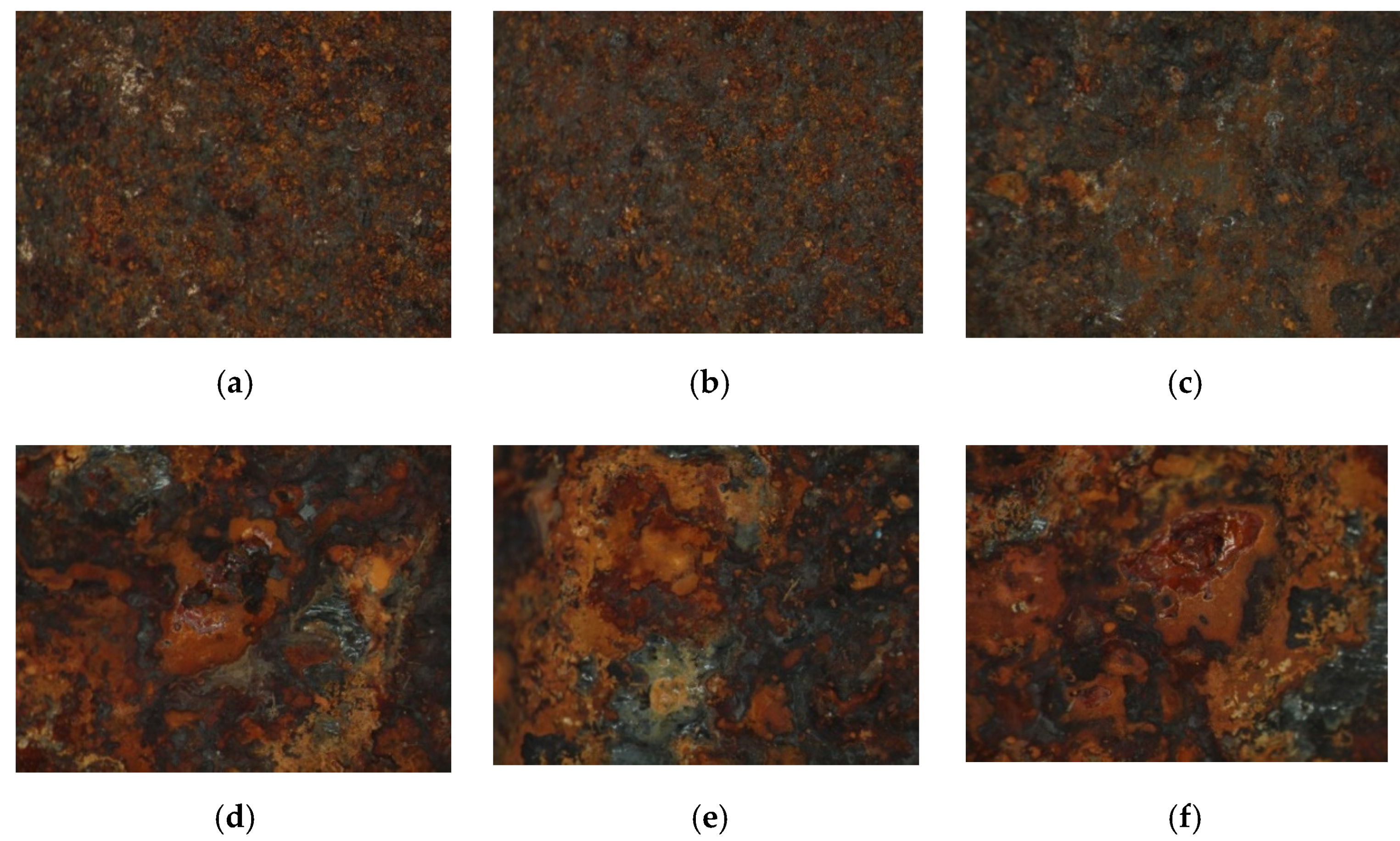
Optical microscope was used to assess the corroded surface at three different areas of specimens: base metal (BM), heat affected zone (HAZ), and weld metal (WM), Figure 5. Visual tests were performed prior to cleaning the specimens, but due to heavily corroded surfaces, priority was given to microscope observations that are presented here. Typical images obtained by optical microscope are presented in Figure 6.
In Table 2, the pit density obtained by processing digital images of corroded surfaces is presented.
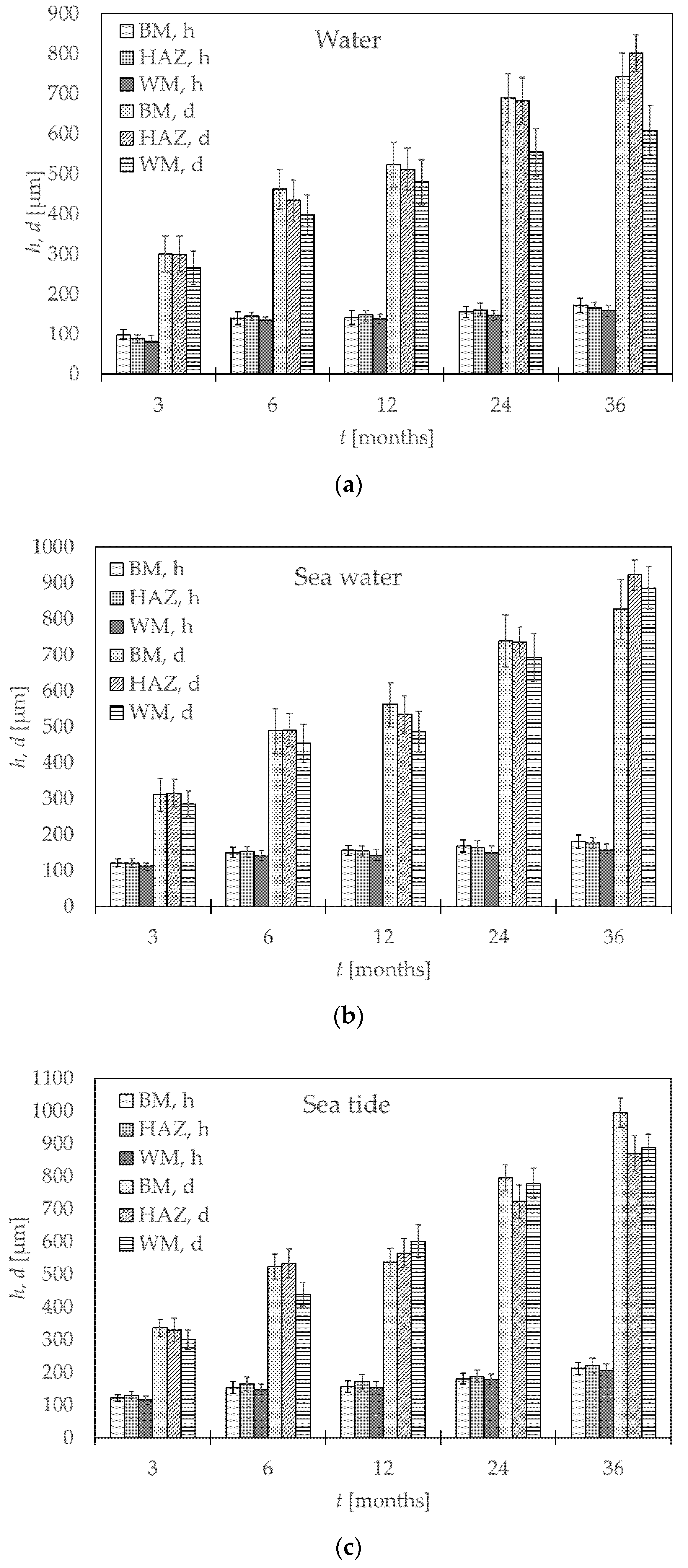
Values of mean pit diameters (d) obtained by optical microscopy along with mean pit depths (h) obtained by measuring actual pit depths with pit depth gauge are presented in Figure 7. Since every group of examined specimens consisted of five items, there was a dissipation of results. Thus, error bars representing standard deviation are also given.
3.3. Corroded Surface Morphology
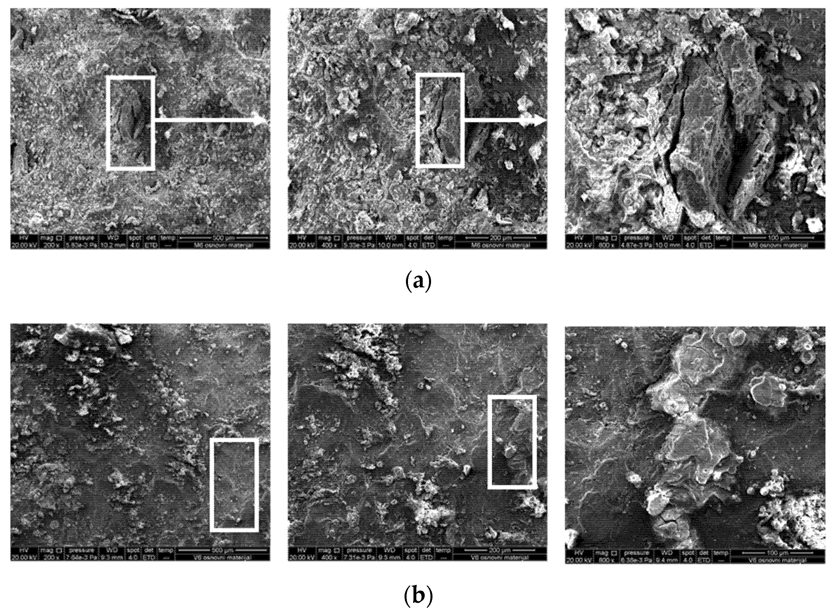
Scanning electron microscope (SEM) was used to assess the corroded surface at three different areas of specimen: base metal (BM), heat affected zone (HAZ), and weld metal (WM); Figure 5. Besides this technique, alternates were used by other authors, such as roughness meters [40]. Typical images obtained by SEM are presented in Figure 8.
4. Discussion
Percentage of mass loss for specimens exposed to different corrosive environments, Figure 3, shows that the significant mass loss occurs after the three-month exposure period. Up to three months, mass loss is negligible. After a six-month exposure period, there is a gain in mass loss, but the rate at which it occurs is somewhat alleviated. This can be contributed to the formation of a protective rust layer on the surface of the metal [41]. However, taking into account the whole 36-month period, one can observe significant mass loss, reaching more than 15% of initial mass. The greatest effect on mass loss was the exposure to sea splash, contributing to combined influence of the corrosive environment (sea) and mechanical loads (splash) [2]. Equations on approximation curves, Figure 3, can help in assessing the mass loss for steel AH36 over the exposure time.
Consistent with previous data, the highest impact on corrosion rate can be observed between the third and sixth month of exposure; Figure 4. Moreover, sea splash generally has the most negative impact on the corrosion rate.
When comparing images of corroded surfaces obtained by optical microscope at three different areas of the specimen exposed to seawater, Figure 6a–c, it can be noted that the number of corrosion pits is highest at the BM area and lowest at the HAZ area. These findings are consistent with pit density values presented in Table 2 and in correlation with previous findings of pit density in austenitic stainless steel welded joints [42].
When comparing images of specimens exposed to the same corrosive environment for two periods (6 and 12 months), Figure 6a–c with Figure 6d–f, it can be noted that pits tend to be larger at specimens exposed for longer periods. On the other hand, pit density tends to be lower for longer periods; Table 2. This is due to fact that pits grow in time and coalesce, making them larger in size, but smaller in number [43].
When assessing a localized corrosion attack, measured pit depth tends to be a better indicator than mass loss. Mean pit depths obtained experimentally, Figure 7, show that the most severe pitting occurs during the first six months of exposure to a corrosive environment. After that, the rate of pit depth growth slows. Moreover, the greatest values of pit depths are measured in the heat-affected zone of the specimens, followed by base material and weld metal. When comparing influence of different corrosive environments, the most negative impact on the surface of the metal has a combined influence of sea and waves (sea splash).
SEM images at three different magnifications (200×, 400×, 800×) for BM of specimens exposed for 6 months to seawater and sea splash, Figure 8, show differences in the shape of the pits at the corroded surfaces. Pits for the metal exposed to the sea have clear and sharp edges, while ones at the metal exposed to the continuous influence of waves have round and smooth edges. These types of smoothed pits present a lower risk of evolving into cracks that could cause failure of a structure [44]. However, generally, greater dimensions of pits at specimens exposed to sea splash than seawater, Figure 8, annulated this fact and bought significant risk of structural integrity loss to the steel structure exposed to the tides.
As for the future direction of the research, it would be useful to study the change of mechanical properties of steel exposed to different types of marine environments for prolonged periods, and to compare them to properties determined at room temperature. Research was conducted on similar steel, various temperatures, and types of environments [45,46,47], but further investigations that are carried out for prolonged periods of exposure, real marine environments, and welded joints could shed additional light on this interesting topic. An educated guess would be that a marine environment could adversely impact the mechanical properties of the steel. Moreover, insight into the change of mechanical properties, due to the change of ambient temperature, would be helpful. Further, the types of experimental data presented in this paper could prove useful in building a numerical model of steel specimen [48] with stochastically distributed corrosion pits over it, performing numerical design optimization [49]. Although there were studies on that matter [10], they did not consider material dissimilarities over BM, HAZ, and WM.
5. Conclusions
To avoid failures, and to help in the preparation of inspection procedures [50], the study of surface conditions of butt-welded specimens made of AH36 shipbuilding steel, exposed to a corrosive marine environment, is presented here. Studying previous similar investigations by other authors, this research has several specific characteristics that need to be emphasized:
- Material was exposed to a natural corrosive environment, which was not the case for most of the previous research studies based in laboratory experiments in simulated environments.
- Exposure to a corrosive environment was performed for prolonged periods, contrary to usual accelerated laboratory tests.
- Findings can be summarized as:
- Exposure between three and six months shows significant influence on mass loss of specimens.
- Sea splash generally has the most negative impact on the corrosion rate due to combined chemical and mechanical degradation of material.
- Pit density is the highest at the BM area of the specimen and lowest at the HAZ area of the specimen.
- The diameter of corrosion pits grows over the time of exposure as the pits coalesce and join.
- Sea splash impacts the shape of the pits, making them rounder and smoother compared to specimens exposed to the sea.
- Pit depths grow fastest during the first six months of exposure to a corrosive environment; after that, the rate of growth tends to slow down.
- Pit depths are generally greatest in the HAZ area of the specimen, followed by BM and WM.
Author Contributions
Conceptualization, G.V. (Goran Vukelic); methodology, G.V. (Goran Vukelic), G.V. (Goran Vizentin); validation J.B.; investigation, G.V. (Goran Vizentin), F.S., M.B.; resources, F.S., M.B.; data curation, G.V. (Goran Vizentin), F.S.; writing—original draft preparation, G.V. (Goran Vukelic); writing—review and editing, J.B., M.B.; supervision, G.V. (Goran Vukelic), J.B.; project administration, G.V. (Goran Vizentin); funding acquisition, G.V. (Goran Vukelic). All authors have read and agreed to the published version of the manuscript.
Funding
This research was funded by the University of Rijeka, grant numbers uniri-technic-18-200 and uniri-technic-18-42. The APC was funded by University of Rijeka.
Institutional Review Board Statement
Not applicable.
Informed Consent Statement
Not applicable.
Acknowledgments
The authors would like to thank Anel Kudic and Branimir Mihaljec, former students of University of Rijeka, Faculty of Maritime Studies, for their technical support.
Conflicts of Interest
The authors declare no conflict of interest. The funders had no role in the design of the study; in the collection, analyses, or interpretation of data; in the writing of the manuscript, or in the decision to publish the results.
References
- Ivošević, Š.; Meštrović, R.; Kovač, N. Probabilistic estimates of corrosion rate of fuel tank structures of aging bulk carriers. Int. J. Nav. Archit. Ocean Eng. 2019, 11, 165–177. [Google Scholar] [CrossRef]
- Ivošević, Š.; Meštrović, R.; Kovač, N. A Probabilistic Method for Estimating the Percentage of Corrosion Depth on the Inner Bottom Plates of Aging Bulk Carriers. J. Mar. Sci. Eng. 2020, 8, 442. [Google Scholar] [CrossRef]
- Vizentin, G.; Vukelic, G.; Murawski, L.; Recho, N.; Orovic, J. Marine propulsion system failures—A review. J. Mar. Sci. Eng. 2020, 8, 662. [Google Scholar] [CrossRef]
- Vukelic, G.; Brnic, J. Predicted fracture behavior of shaft steels with improved corrosion resistance. Metals 2016, 6, 40. [Google Scholar] [CrossRef] [Green Version]
- Vukelic, G.; Brnic, J. Using experimental and numerical characterization in comparing marine exhaust system stainless steels. In Proceedings of the 6th. European Conference on Computational Mechanics (Solids, Structures and Coupled Problems) ECCM 6 and 7th. European Conference on Computational Fluid Dynamics ECFD 7; Owen, R., de Borst, R., Reese, J., Pearce, C., Eds.; CIMNE: Glasgow, UK, 2018; pp. 4423–4431. [Google Scholar]
- Kozak, J.; Tarełko, W. Case study of masts damage of the sail training vessel POGORIA. Eng. Fail. Anal. 2011, 18, 819–827. [Google Scholar] [CrossRef]
- Zunkel, A.; Tiebe, C.; Schlischka, J. “Stolt Rotterdam”–The sinking of an acid freighter. Eng. Fail. Anal. 2014, 43, 221–231. [Google Scholar] [CrossRef]
- Lo, M.; Karuppanan, S.; Ovinis, M. Failure Pressure Prediction of a Corroded Pipeline with Longitudinally Interacting Corrosion Defects Subjected to Combined Loadings Using FEM and ANN. J. Mar. Sci. Eng. 2021, 9, 281. [Google Scholar] [CrossRef]
- Salazar-Domínguez, C.M.; Hernández-Hernández, J.; Rosas-Huerta, E.D.; Iturbe-Rosas, G.E.; Herrera-May, A.L. Structural Analysis of a Barge Midship Section Considering the Still Water and Wave Load Effects. J. Mar. Sci. Eng. 2021, 9, 99. [Google Scholar] [CrossRef]
- Xu, S.; Wang, H.; Li, A.; Wang, Y.; Su, L. Effects of corrosion on surface characterization and mechanical properties of butt-welded joints. J. Constr. Steel Res. 2016, 126, 50–62. [Google Scholar] [CrossRef]
- Česen, A.; Kosec, T.; Legat, A. Characterization of steel corrosion in mortar by various electrochemical and physical techniques. Corros. Sci. 2013, 75, 47–57. [Google Scholar] [CrossRef] [Green Version]
- Reiser, D.B.; Alkire, R.C. The measurement of shape change during early stages of corrosion pit growth. Corros. Sci. 1984, 24, 579–585. [Google Scholar] [CrossRef]
- Holme, B.; Lunder, O. Characterisation of pitting corrosion by white light interferometry. Corros. Sci. 2007, 49, 391–401. [Google Scholar] [CrossRef]
- Ren, Z.; Ernst, F. Stress–Corrosion Cracking of AISI 316L Stainless Steel in Seawater Environments: Effect of Surface Machining. Metals 2020, 10, 1324. [Google Scholar] [CrossRef]
- He, J.; Xu, S.; Ti, W.; Han, Y.; Mei, J.; Wang, X. The Pitting Corrosion Behavior of the Austenitic Stainless Steel 308L-316L Welded Joint. Metals 2020, 10, 1258. [Google Scholar] [CrossRef]
- Melchers, R.E. Long-Term Durability of Marine Reinforced Concrete Structures. J. Mar. Sci. Eng. 2020, 8, 290. [Google Scholar] [CrossRef] [Green Version]
- Melchers, R.E. Experience-Based Physico-Chemical Models for Long-Term Reinforcement Corrosion. Corros. Mater. Degrad. 2021, 2, 6. [Google Scholar] [CrossRef]
- Kim, D.K.; Wong, E.W.C.; Cho, N.K. An advanced technique to predict time-dependent corrosion damage of onshore, offshore, nearshore and ship structures: Part I = generalisation. Int. J. Nav. Archit. Ocean Eng. 2020, 12, 657–666. [Google Scholar] [CrossRef]
- Kim, D.K.; Lim, H.L.; Cho, N.K. An advanced technique to predict time-dependent corrosion damage of onshore, offshore, nearshore and ship structures: Part II = Application to the ship’s ballast tank. Int. J. Nav. Archit. Ocean Eng. 2020, 12, 645–656. [Google Scholar] [CrossRef]
- Świerczyńska, A.; Fydrych, D.; Landowski, M.; Rogalski, G.; Łabanowski, J. Hydrogen embrittlement of X2CrNiMoCuN25-6-3 super duplex stainless steel welded joints under cathodic protection. Constr. Build. Mater. 2020, 238, 117697. [Google Scholar] [CrossRef]
- Świerczyńska, A.; Landowski, M. Plasticity of Bead-on-Plate Welds Made with the Use of Stored Flux-Cored Wires for Offshore Applications. Materials 2020, 13, 3888. [Google Scholar] [CrossRef] [PubMed]
- Paik, J.K.; Thayamballi, A.K.; Park, Y.I. Hwang, J.S. A time-dependent corrosion wastage model for seawater ballast tank structures of ships. Corros. Sci. 2004, 46, 471–486. [Google Scholar] [CrossRef]
- Guedes Soares, C.; Garbatov, Y.; Zayed, A.; Wang, G. Corrosion wastage model for ship crude oil tanks. Corros. Sci. 2008, 50, 3095–3106. [Google Scholar] [CrossRef]
- Soares, C.G.; Garbatov, Y.; Zayed, A.; Wang, G. Influence of environmental factors on corrosion of ship structures in marine atmosphere. Corros. Sci. 2009, 51, 2014–2026. [Google Scholar] [CrossRef]
- Paik, J.K.; Kim, D.K. Advanced method for the development of an empirical model to predict time-dependent corrosion wastage. Corros. Sci. 2012, 63, 51–58. [Google Scholar] [CrossRef]
- Mohd, M.H.; Kim, D.K.; Kim, D.W.; Paik, J.K. A time-variant corrosion wastage model for subsea gas pipelines. Ships Offshore Struct. 2014, 9, 161–176. [Google Scholar] [CrossRef]
- Saeed, A.; Khan, Z.A.; Nazir, M.H. Time dependent surface corrosion analysis and modelling of automotive steel under a simplistic model of variations in environmental parameters. Mater. Chem. Phys. 2016, 178, 65–73. [Google Scholar] [CrossRef]
- Pastorcic, D.; Vukelic, G.; Bozic, Z. Coil spring failure and fatigue analysis. Eng. Fail. Anal. 2019. [Google Scholar] [CrossRef]
- Chen, J.; Zhang, W.; Gu, X. Modeling time-dependent circumferential non-uniform corrosion of steel bars in concrete considering corrosion-induced cracking effects. Eng. Struct. 2019, 201, 109766. [Google Scholar] [CrossRef]
- Yu, Y.; Gao, W.; Castel, A.; Chen, X.; Liu, A. An integrated framework for modelling time-dependent corrosion propagation in offshore concrete structures. Eng. Struct. 2021, 228, 111482. [Google Scholar] [CrossRef]
- Choi, Y.Y.; Lee, S.H.; Park, J.C.; Choi, D.J.; Yoon, Y.S. The impact of corrosion on marine vapour recovery systems by VOC generated from ships. Int. J. Nav. Archit. Ocean Eng. 2019, 11, 52–58. [Google Scholar] [CrossRef]
- Schoefs, F.; Boéro, J.; Capra, B. Long-Term Stochastic Modeling of Sheet Pile Corrosion in Coastal Environment from On-Site Measurements. J. Mar. Sci. Eng. 2020, 8, 70. [Google Scholar] [CrossRef] [Green Version]
- Duan, T.; Peng, W.; Ding, K.; Guo, W.; Hou, J.; Cheng, W.; Liu, S.; Xu, L. Long-term field exposure corrosion behavior investigation of 316L stainless steel in the deep sea environment. Ocean Eng. 2019, 189, 106405. [Google Scholar] [CrossRef]
- Martins, K.L.; Pinto, V.T.; Fragassa, C.; Real, M.V.; Rocha, L.A.O.; Isoldi, L.A.; dos Santos, E.D. A Simplified Numerical Method for the Design and Analysis of FPSO Platform Brackets Subjected to Operational Conditions. J. Mar. Sci. Eng. 2020, 8, 929. [Google Scholar] [CrossRef]
- Kim, J.D.; Myoung, G.H.; Suh, J. Butt weldability of shipbuilding steel AH36 using laser-arc hybrid welding. Trans. Korean Soc. Mech. Eng. A 2016, 40, 901–906. [Google Scholar] [CrossRef]
- Dueren, C.F. Prediction of the hardness in the HAZ of HSLA steels by means of the C-equivalent. In Proceedings of the Conference on Hardenability of Steels 1990, Derby, UK, 17 May 1990. [Google Scholar]
- Institute of Oceanography and Fisheries. Početna Procjena Stanja i Opterećenja Morskog Okoliša Hrvatskog Dijela Jadrana; Institute of Oceanography and Fisheries: Split, Croatia, 2012. [Google Scholar]
- Garbatov, Y.; Saad-Eldeen, S.; Guedes Soares, C.; Parunov, J.; Kodvanj, J. Tensile test analysis of corroded cleaned aged steel specimens. Corros. Eng. Sci. Technol. 2019, 54, 154–162. [Google Scholar] [CrossRef]
- American Society for Testing and Materials, ASTM G1-03 Standard Practice for Preparing, Cleaning and Evaluating Corrosion Test Specimens; West Conshohocken: Montgomery County, PA, USA, 2011.
- Florescu, S.N.; Gheonea, M.C.; Mihailescu, D.; Teodor, V. Influence of marine corrosion on the roughness of MAG welded joint surfaces. In Proceedings of the IOP Conference Series: Materials Science and Engineering; IOP Publishing Ltd.: Bristol, UK, 2020; Volume 968, p. 012008. [Google Scholar]
- Muthanna, B.G.N.; Amara, M.; Meliani, M.H.; Mettai, B.; Božić, Ž.; Suleiman, R.; Sorour, A.A. Inspection of internal erosion-corrosion of elbow pipe in the desalination station. Eng. Fail. Anal. 2019. [Google Scholar] [CrossRef]
- Luo, L.; Huang, Y.; Weng, S.; Xuan, F.Z. Mechanism-related modelling of pit evaluation in the CrNiMoV steel in simulated environment of low pressure nuclear steam turbine. Mater. Des. 2016, 105, 240–250. [Google Scholar] [CrossRef]
- Li, S.X.; Akid, R. Corrosion fatigue life prediction of a steel shaft material in seawater. Eng. Fail. Anal. 2013, 34, 324–334. [Google Scholar] [CrossRef]
- Zerbst, U.; Madia, M.; Klinger, C.; Bettge, D.; Murakami, Y. Defects as a root cause of fatigue failure of metallic components. III: Cavities, dents, corrosion pits, scratches. Eng. Fail. Anal. 2019, 97, 759–776. [Google Scholar] [CrossRef]
- Rajput, A.; Park, J.H.; Hwan Noh, S.; Kee Paik, J. Fresh and sea water immersion corrosion testing on marine structural steel at low temperature. Ships Offshore Struct. 2020, 15, 661–669. [Google Scholar] [CrossRef]
- Rajput, A.; Paik, J.K. Effects of naturally-progressed corrosion on the chemical and mechanical properties of structural steels. Structures 2021, 29, 2120–2138. [Google Scholar] [CrossRef]
- Tavares, S.S.M.; Batista, R.T.; Landim, R.V.; Velasco, J.A.C.; Senna, L.F. Investigation of the effect of low temperature aging on the mechanical properties and susceptibility to sulfide stress corrosion cracking of 22%Cr duplex stainless steel. Eng. Fail. Anal. 2020, 113, 104553. [Google Scholar] [CrossRef]
- Kodvanj, J.; Garbatov, Y.; Guedes Soares, C.; Parunov, J. Numerical Analysis of Stress Concentration in Non-uniformly Corroded Small-Scale Specimens. J. Mar. Sci. Appl. 2020, 1–9. [Google Scholar] [CrossRef]
- Vukelic, G.; Vizentin, G.; Masar, A. Hydraulic torque wrench adapter failure analysis. Eng. Fail. Anal. 2019, 96, 530–537. [Google Scholar] [CrossRef]
- Poggi, L.; Gaggero, T.; Gaiotti, M.; Ravina, E.; Rizzo, C.M. Recent developments in remote inspections of ship structures. Int. J. Nav. Archit. Ocean Eng. 2020, 12, 881–891. [Google Scholar] [CrossRef]
Figure 1.
Welded blanks with cut out specimens.

Figure 2.
Exposure of specimens to corrosive environment: (a) water, (b) seawater, (c) sea splash.

Figure 3.
Average percentage of mass loss (ML) for AH36 steel specimens exposed over time (t) to air, water, seawater, and sea splash for 3, 6, 12, 24, and 36 months.
Figure 3.
Average percentage of mass loss (ML) for AH36 steel specimens exposed over time (t) to air, water, seawater, and sea splash for 3, 6, 12, 24, and 36 months.

Figure 4.
Average corrosion rate (CR) for AH36 steel specimens exposed over time (t) to air, water, seawater, and sea splash for 3, 6, 12, 24, and 36 months.
Figure 4.
Average corrosion rate (CR) for AH36 steel specimens exposed over time (t) to air, water, seawater, and sea splash for 3, 6, 12, 24, and 36 months.

Figure 5.
Areas of specimens observed by microscope: base metal—BM, heat affected zone—HAZ and weld metal—WM.
Figure 5.
Areas of specimens observed by microscope: base metal—BM, heat affected zone—HAZ and weld metal—WM.

Figure 6.
Optical microscope images of specimens exposed to seawater at magnification of 32× for: (a) BM, 6 months exposure; (b) HAZ, 6 mt.; (c) WM, 6 mt.; (d) BM, 12 mt.; (e) HAZ, 12 mt.; (f) WM, 12 mt.
Figure 6.
Optical microscope images of specimens exposed to seawater at magnification of 32× for: (a) BM, 6 months exposure; (b) HAZ, 6 mt.; (c) WM, 6 mt.; (d) BM, 12 mt.; (e) HAZ, 12 mt.; (f) WM, 12 mt.

Figure 7.
Values of average pit depth (h) and pit diameter (d) of specimens over exposed time (t). (a) water, (b) sea water, (c) sea tide.
Figure 7.
Values of average pit depth (h) and pit diameter (d) of specimens over exposed time (t). (a) water, (b) sea water, (c) sea tide.

Figure 8.
SEM images at magnification of 200×, 400×, and 800× for BM specimen area exposed for 6 months to: (a) sea water, (b) sea splash.
Figure 8.
SEM images at magnification of 200×, 400×, and 800× for BM specimen area exposed for 6 months to: (a) sea water, (b) sea splash.


Table 1.
Chemical composition of AH36 steel (wt %).
| C | Si | Mn | P | S | Cr | Cu | Al | Ti | V | Mo | Ni | CEq |
|---|---|---|---|---|---|---|---|---|---|---|---|---|
| 0.157 | 0.392 | 1.501 | 0.014 | 0.003 | 0.03 | 0.015 | 0.042 | 0.003 | 0.003 | 0.08 | 0.01 | 0.2763 |
Table 2.
Pit density.
| Environment: | Water | ||||||||||||||
|---|---|---|---|---|---|---|---|---|---|---|---|---|---|---|---|
| Location: | BM | HAZ | WM | ||||||||||||
| Exposure Time (months): | 3 | 6 | 12 | 24 | 36 | 3 | 6 | 12 | 24 | 36 | 3 | 6 | 12 | 24 | 36 |
| Pit density (10 mm−2): | 3 ± 1 | 4 ± 1 | 5 ± 1 | 4 ± 1 | 5 ± 1 | 2 ± 1 | 3 ± 1 | 5 ± 2 | 4 ± 1 | 5 ± 1 | 2 ± 1 | 2 ± 1 | 3 ± 1 | 3 ± 1 | 4 ± 1 |
| Environment: | Seawater | ||||||||||||||
| Location: | BM | HAZ | WM | ||||||||||||
| Exposure Time (months): | 3 | 6 | 12 | 24 | 36 | 3 | 6 | 12 | 24 | 36 | 3 | 6 | 12 | 24 | 36 |
| Pit Density (10 mm−2): | 6 ± 1 | 9 ± 3 | 6 ± 2 | 5 ± 2 | 5 ± 1 | 2 ± 1 | 3 ± 1 | 3 ± 1 | 2 ± 1 | 2 ± 2 | 4 ± 1 | 7 ± 2 | 6 ± 2 | 6 ± 1 | 5 ± 1 |
| Environment: | Sea splash | ||||||||||||||
| Location: | BM | HAZ | WM | ||||||||||||
| Exposure Time (months): | 3 | 6 | 12 | 24 | 36 | 3 | 6 | 12 | 24 | 36 | 3 | 6 | 12 | 24 | 36 |
| Pit Density (10 mm−2): | 4 ± 1 | 6 ± 2 | 6 ± 2 | 5 ± 1 | 5 ± 1 | 3 ± 2 | 5 ± 2 | 5 ± 2 | 4 ± 1 | 5 ± 1 | 2 ± 1 | 4 ± 1 | 3 ± 1 | 3 ± 1 | 2 ± 1 |
Publisher’s Note: MDPI stays neutral with regard to jurisdictional claims in published maps and institutional affiliations. |
© 2021 by the authors. Licensee MDPI, Basel, Switzerland. This article is an open access article distributed under the terms and conditions of the Creative Commons Attribution (CC BY) license (https://creativecommons.org/licenses/by/4.0/).
Share and Cite
MDPI and ACS Style
Vukelic, G.; Vizentin, G.; Brnic, J.; Brcic, M.; Sedmak, F. Long-Term Marine Environment Exposure Effect on Butt-Welded Shipbuilding Steel. J. Mar. Sci. Eng. 2021, 9, 491. https://doi.org/10.3390/jmse9050491
AMA Style
Vukelic G, Vizentin G, Brnic J, Brcic M, Sedmak F. Long-Term Marine Environment Exposure Effect on Butt-Welded Shipbuilding Steel. Journal of Marine Science and Engineering. 2021; 9(5):491. https://doi.org/10.3390/jmse9050491
Chicago/Turabian StyleVukelic, Goran, Goran Vizentin, Josip Brnic, Marino Brcic, and Florian Sedmak. 2021. "Long-Term Marine Environment Exposure Effect on Butt-Welded Shipbuilding Steel" Journal of Marine Science and Engineering 9, no. 5: 491. https://doi.org/10.3390/jmse9050491
Note that from the first issue of 2016, this journal uses article numbers instead of page numbers. See further details here.