


1. Introduction
Subglacial lakes are discrete water bodies that lie at the base of an ice sheet between the ice and substrate (Siegert, Reference Siegert2000). Since the first discovery of the Antarctic subglacial lake by radio echo detection in the 1960s, scientists have been searching for and studying subglacial lakes. By the end of 2015, 402 Antarctic subglacial lakes had been discovered (Siegert and others, Reference Siegert, Ross and Brocq2016; Siegert, Reference Siegert2017). The study of subglacial lakes is crucial for analyzing the dynamic mechanism of subglacial lake formation, the evolutionary process of the subglacial lake and its influence on the evolution of primitive life, retrieving the history of the ice sheet, obtaining paleoclimate records and analyzing the influence of subglacial hydrological systems on the dynamic evolution of ice sheet. The subglacial lake is also considered to be an extreme habitat for microorganisms because it is cold, deep and isolated (Xiao and others, Reference Xiao, Qin and Ren2001; Mowlem and others, Reference Mowlem2016; Siegert, Reference Siegert2017). Therefore, the study of the subglacial lake has become a hot spot in polar science research.
To study the subglacial lake, in situ physical and chemical measurement, lake water sampling, suspended particle sampling and sediment sampling are needed. In situ observation and water sampling can be achieved by drilling through the ice sheet and entering the subglacial lake through a drilling probe with measuring devices and samplers. To achieve this goal, many countries have undertaken exploration programs for Antarctic subglacial lakes, such as the Russian research project on Vostok Lake (Bulat, Reference Bulat2016; Leitchenkov and others, Reference Leitchenkov, Antonov, Luneov and Lipenkov2016), the US research project on Whillans Lake (Priscu and others, Reference Priscu2013; Vick-Majors and others, Reference Vick-Majors2016) and the UK research project on Ellsworth Lake (Makinson and others, Reference Makinson2016; Pearce and others, Reference Pearce2016). To minimize pollution of the lake water during drilling and sampling, China launched a project titled ‘Research and Development (R&D) of pollution-free drilling, sampling, and observation system in Antarctic subglacial lakes’ in 2016 through the National Key R&D Program. The project utilizes the Recoverable Autonomous Sonde (RECAS) proposed by Talalay and others (Reference Talalay, Zagorodnov, Markov, Sysoev and Hong2014) and is based on the Philberth probe (Philberth, Reference Philberth1974). The addition of the upper thermal tip and the cable recoiling mechanism allows for in situ measurement and sampling in isolation from the outside environment, as shown in Figure 1a. In addition to the thermal tip, the addition of lateral heater is a necessity to prevent the long-length RECAS from freezing in the low-temperature ice sheet (Talalay and others, Reference Talalay, Zagorodnov, Markov, Sysoev and Hong2014), as shown in Figures 1b and c. In Figure 1b, h f represents the critical refreezing length, that is, the maximum length that does not require a lateral heater. In Li and others (Reference Li2020a), the Li team combined measured data from RECAS thermal heads with the theoretical analysis results in Schüller and Kowalski (Reference Schüller and Kowalski2019) and deduced that the RECAS h f at −10, −20 and −30°C should be 4.5, 2.2 and 1.5 m, respectively. Notably, according to the theory originally proposed by Aamot (Reference Aamot1967), lateral heating requirements were heterogeneously distributed along the length of a moving thermal probe, gradually decreasing from the bottom to the top, as shown in Figure 1c. The two thermal tips of RECAS are heated separately according to the different drilling directions. Therefore, during the drilling process of RECAS, heating switch control of the upper and lower thermal tips is required according to the drilling direction, as well as to achieve multi-section control of the lateral heaters, allowing for an overall heating control system.
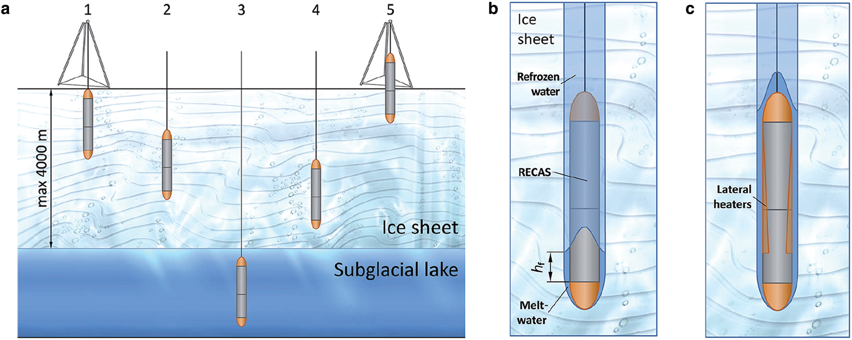
Fig. 1. Concept of RECAS proposed in (Talalay and others, Reference Talalay, Zagorodnov, Markov, Sysoev and Hong2014): (a) RECAS workflow; (b) maximum length, h f, which does not require a lateral heater; (c) theoretically heterogeneously distributed RECAS lateral heaters.
This study designed and implemented a heating control system for the 200 m prototype of RECAS (hereinafter referred to as RECAS-200). The main contributions of this study are as follows:
(1) To decrease the total weight of RECAS-200 to reduce the load-bearing requirements of the cable and thereby reduce the diameter of the cable, the use of high-power step-down voltage converter must be limited. For this purpose, this study proposes a separate solution for heating power and control power, in which the heating power acts directly on the customized heating elements without voltage converters, while the control power uses fewer low-power transformers to reduce the voltage to an appropriate value.
(2) To facilitate heating element temperature control, it is necessary to add a power regulator between the downhole power supply and heating element. The output voltage of the commercial solid-state power regulator is extremely small (220/380 VAC), and the commercial thyristor controller is extremely large, precluding them from the RECAS-200. In response, a small-sized 800 VAC solid-state power regulator based on bidirectional thyristor is developed in this study to complete the power regulation of the different heating elements.
(3) Some components may be burnt due to poor heat dissipation conditions, particularly the coaxial cable passing through the upper thermal tip (temperature tolerance is 100°C). To ensure the safety of RECAS-200 during the upward drilling process, a closed-loop temperature control method based on the fuzzy Proportion-Integration-Differentiation (PID) algorithm (Dequan and others, Reference Dequan, Guili, Zhiwei and Peng2012) is introduced in addition to a temperature sensor installed in the thermal tip.
The remainder of this study is organized as follows. The RECAS and RECAS-200 are briefly described in Section 2. The heating system of RECAS-200 is discussed in Section 3. Section 4 describes the proposed heating control system in detail. Section 5 presents the system test results. Finally, Section 6 concludes the study.
2. Brief description of RECAS and RECAS-200
The RECAS concept was proposed by Talalay and others (Reference Talalay, Zagorodnov, Markov, Sysoev and Hong2014), and its design is based on the Philberth thermal probe, as shown in Figure 2. The Philberth thermal probe is characterized by a coiled wire inside the probe for the transmission of electrical power and signals, which is paid out when it is advancing and becomes fixed in the ice below the frozen meltwater. Unlike the non-recoverable Philberth probe, RECAS has two thermal tips located at both ends of the probe. As a result, RECAS can be recovered using a cable recoiling mechanism. The main working principles of RECAS are: (1) The electric power and signal cable are coiled inside the probe on an electric-motor-powered coil. (2) When the lower thermal tip is powered, the probe advances downward owing to gravity. (3) To move the probe up, power is applied to the upper thermal tip and the coil motor pulls the cable, moving the probe upward and melting the borehole above the probe. The main parameters of RECAS are shown in Table 1.
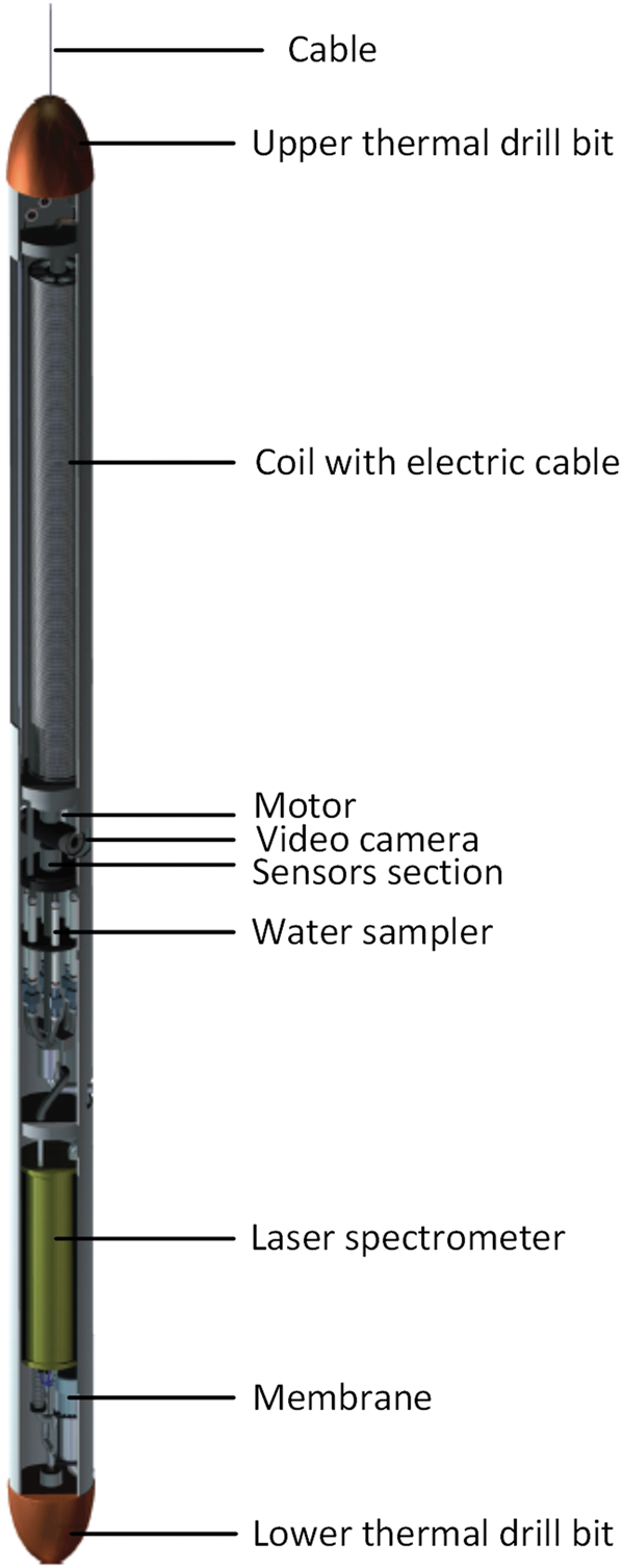
Fig. 2. Conceptual diagram of RECAS.
Table 1. Main parameters of RECAS and RECAS-200

The RECAS-200 is the 200 m prototype of RECAS. As the drum of RECAS-200 can only hold ~200 m of cable, it can achieve a drilling depth within 200 m under the ice. When implementing RECAS-200, we adopted the structure shown in Figure 3 and completed the following detailed design work: (1) To increase the cable strength without increasing the diameter of the cable, the power line carrier technology is adapted to use a coaxial cable for both the power supply and signal transmission. (2) A pulley-driven system is added to greatly reduce the force on the cable. (3) Both thermal tips include multiple cartridge heaters in a copper body, as described in Li and others (Reference Li2020a), and as shown in Figure 4. (4) Although theoretically the lateral heaters should be heterogeneously distributed, according to the results discussed in Li and others (Reference Li, Yang, Fan, Li and Talalay2020b), for safety and convenience, we adjusted the lateral heaters of RECAS-200 to a uniform distribution, under the premise of sufficient heating power density. Meanwhile, to facilitate disassembly and assembly, we fabricated the lateral heaters as four lateral heating tubes. The lateral heating tube is constructed by winding a single thin heating strip on a copper tube. Furthermore, as the area within h f will not freeze when the thermal tip is turned on, and the transformers can generate heat, the lateral heaters do not need to cover the entire probe. Therefore, we did not add lateral heaters to the outer wall of the transformers (length 0.62 m) and the area where the two thermal tips are located (length 0.7 m). During drilling, the thermal tip opposite to the drilling direction can turn on a small part of the power to prevent its corresponding 0.7 m area from freezing. (5) To prevent damage to the heating elements during overheating, a power regulator and a temperature sensor are embedded in each heating element to facilitate closed-loop temperature control. (6) Owing to the shorter length of the cable and reduced power losses, the power supply did not require 3000–4000 VDC high voltage, which allowed a lower voltage of 800 VAC power supply to be adopted. The DC power required for the measurement and control system is obtained by transformers and AC-DC converters. (7) To reduce the length of RECAS-200, the in situ measurement and sampling part is limited to pressure (P), temperature (T), pH and conductivity sensors, and two 200 mL sampling bottles.
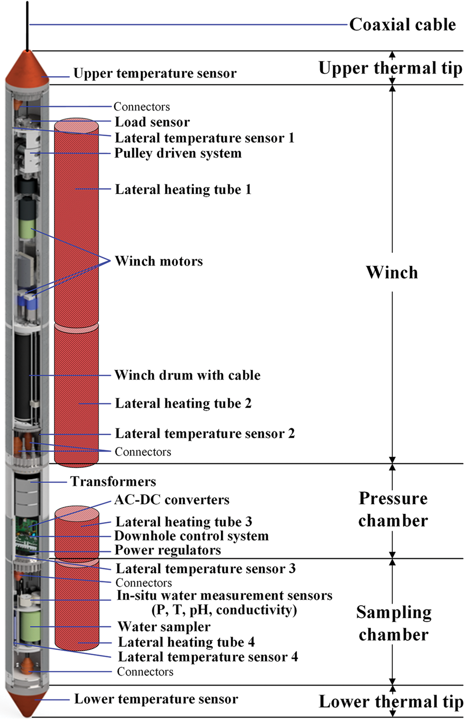
Fig. 3. Structural diagram of RECAS-200 (not to scale).

Fig. 4. Structure of the two RECAS-200 thermal tips, as improved by Li and others from the initial version proposed in Li and others (Reference Li2020a): (a) upper thermal tip; (b) lower thermal tip.
The main RECAS-200 parameters, incorporating the design characteristics discussed above, are shown in Table 1; to facilitate comparison, the basic RECAS parameters have also been included. Table 1 shows that, for RECAS-200, apart from the fact that drilling cannot reach 3500 m due to the space limitation of the cable, the diameter of the thermal tip, probe housing and cable, as well as the drilling speed, were all worse than RECAS. This was because we have not been able to obtain a cable thin enough to meet the RECAS design criteria. As the cable is accommodated in the probe, the diameter of the probe (including two thermal tips) must increase with an increase in the cable diameter, assuming the same probe length. Furthermore, at the same power, when the probe diameter increases, its drilling speed will inevitably decrease.
3. Overview of the heating system of RECAS-200
The RECAS-200 heating system is composed of a power supply system, heating elements and heating control system, as shown in Figure 5. According to the electrical characteristics of the coaxial cable, the power supply system boosts the 220 VAC output from the single-phase generator to 800 VAC with the aid of a booster cabinet and transmits it to the probe. The booster cabinet has sufficient power to ensure the normal drilling power of the probe (at least 9.6 kW). The total length of the coaxial cable is 300 m, part of which is stored in the drum (length 200 m) inside the probe, with the rest laid on the surface and hung in the drill tower, to connect to the booster cabinet. The heating elements include two thermal tips and four lateral heating tubes, which are used to convert electrical energy into heat required for ice melting, to maintain the required drilling speed while preventing refreezing. The heating control system includes three parts: (1) a DC power supply system for control power, including step-down transformers and AC-DC converters; (2) temperature sensors (upper temperature sensor, lower temperature sensor and lateral temperature sensor 1–4) and power regulators for heating power adjustment and closed-loop temperature control; (3) a heating control algorithm, which runs in the downhole control system, using the power regulators and temperature sensors to complete the on-off control and the power regulation of each heating element, and the closed-loop temperature control for certain heating elements.

Fig. 5. RECAS-200 heating system.
Notably, to ensure that the temperature sensor reliably reflected the actual temperature of the heating element, we directly inserted all the temperature sensing elements of the lateral temperature sensors into the holes reserved for the lateral copper tubes, to ensure that the two were in close contact, as shown in Figure 5. Due to the high heating power and temperature of the thermal tips, which may reach 300°C, the circuits inside the temperature sensor cannot work normally, requiring the temperature sensor to be separated into two parts. The temperature sensing element was embedded in the copper body of the thermal tip, and the circuit part was fixed on the pressure chamber cover, with the two parts connected by high-temperature wires, as shown in Figure 4. In addition, it was difficult to install a temperature sensing element in the contact area between the coaxial cable and copper body of the upper thermal tip (as shown in Fig. 4). This was important as the coaxial cable passing through the conical upper thermal tip is easily burnt by overheating. Therefore, the temperature of the contact position could only be estimated using the temperature of the sensing element embedded in the backplane of the copper cone. Temperature estimation for the contact position and the corresponding temperature control have been discussed in more detail in Section 4.3.
4. The proposed heating control system
In the RECAS-200 heating control system as described in Section 3, the waterproof and high-pressure-resistant temperature probe developed by our laboratory is used. The DC power supply system (step-down transformers and AC-DC converters), power regulator and heating control algorithm will be discussed in more detail in this section.
4.1 Downhole power supply system based on the separation of heating power and control power
The detailed downhole power distribution of RECAS-200 is shown in Table 2, excluding the power losses in the cable. From Table 2, the downhole power of RECAS-200 can be divided into two parts, namely heating power (consumed by heating elements) and control power (consumed by winch motors, control systems, sensors and other electronic systems). As the heating elements can work directly at AC voltage, the heating power does not need to be converted from AC to DC. However, as the electronic equipment, such as the winch motor (DC motor), control system and sensors can only work at low-voltage DC power, the power supply of the control power must be converted from AC to DC.
Table 2. Downhole power distribution of RECAS-200

After consulting multiple heating element manufacturers, we found that the highest operating AC voltages for commercial cartridge heaters and heating strips were 220/380 V. The cartridge heater resistors were also seriously unbalanced, and consequently, the heaters could not be used in series for any length of time. When cartridge heaters and heating strips that could not work with 800 VAC were to be used, a high-power converter, with a power of ~10 kW, had to be introduced to step down the voltage. The high-power converters are usually large and heavy, making them unsuitable for this application as they would not fit within the size and weight limitations, and the load ratings of the deployment cable. After detailed discussions with several heating element manufacturers, we asked Liangdong Technology (Liangdong-Technology, 2020) to design new cartridge heaters, which were capable of a maximum operating voltage of 400 VAC, and could be used reliably in series and heating strips that could work directly with 1000 VAC. In this way, all heating elements were able to work directly with 800 VAC, thereby eliminating the need for high-power voltage converters.
As mentioned above, the control power cannot avoid the use of a voltage converter. However, as control power only accounts for a small part of the total power (1.1 kW), a small number of transformers could easily achieve the required voltage conversion, that is, a small number of transformers could complete the separation of control power from heating power. Considering the large instantaneous current when the winch motor starts and stops, there should be a margin for the control power. Therefore, three toroidal transformers with a single power of 700 W are selected to complete the separation of heating power and control power.
Using the above-mentioned power supply strategy, and according to the maximum operating voltage of the heating elements (800 VAC) and the electrical characteristics of the cable, the main power supply parameters of RECAS-200 can be calculated as seen in Table 3. The downhole power supply scheme of RECAS-200 based on the separation of heating power and control power is shown in Figure 6.
Table 3. Calculated values of the power and voltage supply on the surface
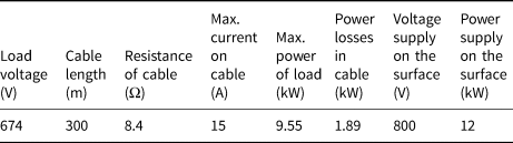

Fig. 6. Proposed downhole power supply scheme of RECAS-200.
4.2 Self-developed 800 VAC small-sized solid-state power regulator
The highest output voltage of the commercial small-sized solid-state power regulator is 220/380 VAC. To increase the output voltage, we can use a combination of a high-voltage thyristor and a commercial thyristor controller. However, as the commercial controllers for thyristors are usually designed for large current output, they are bulky relative to the slender barrel-shaped pressure chamber of RECAS-200. Thus, we developed a small-sized solid-state power regulator with an output voltage of 800 VAC that directly integrates the small-sized controller and the medium power thyristor. This allows for power regulation of the heating elements while occupying only a very small space in the pressure chamber.
Cycle power regulation can switch the thyristor at zero-crossing, thereby minimizing device damage and power consumption. This process is relatively simple to implement, and as power output is stable, it has often been used for heating power control. Therefore, the cycle power regulation method is selected in this study. The fixed-period method is adopted to complete the power regulation bypass or cut the sine cycles proportionally within a given time. In this study, the given period is 1 s, and the sine cycle period is 20 ms (50 Hz). There is a total of 50 sine cycles in the given period, and the power regulation is performed by passing or cutting these 50 sine cycles, as shown in Figure 7. The resolution of power regulation, that is, the percentage of minimum power regulation, can be determined as 20 ms/1 s = 2%.

Fig. 7. Principle of the cycle power regulation method.
Table 3 shows that the maximum power supply voltage on the surface was 800 VAC, so that, when not all heating elements were turned on, the maximum power regulator voltage was 800 VAC. Furthermore, Figure 6 shows that the maximum power regulated by a single power regulator is half of the maximum power of a single thermal tip, that is, 2.5 kW. Meanwhile, it could be deduced from the lowest operating voltage of the AC–DC module (180 VAC) and the transformation ratio of the toroidal transformer (3.33), that the lowest downhole voltage was 600 VAC, indicating that the maximum current through a single power regulator was 2.5 kW/600 V = 4.17 A. After leaving a certain margin, it was established that the maximum power regulator operating current was 5 A. Based on this maximum operating voltage and current of the power regulator, we selected a medium-power, bidirectional thyristor (model BCR20RM-30LA from Renesas Electronics Corp., Japan), whose maximum peak voltage was 1500 V and whose maximum continuous current was 20 A. The structure of the self-developed 800 VAC power regulator, incorporating the BCR20RM-30LA thyristor, is demonstrated in Figure 8. The main function of the zero-crossing detection circuit is to ensure that the power regulator turns the AC power on or off when the waveform passes through zero, which increases the service life of the bidirectional thyristor and reduce its impact on the power supply system. The pulse-width modulation (PWM) to DC conversion circuit is used to convert the external PWM control signal into an analog DC signal. The controller of the power regulator can quickly receive the signal and respond accordingly. In order to prevent the thyristor from overheating and then burning out due to the excessive current, an overheat protection circuit is added to automatically turn off the thyristor when the thyristor's current is more than 15 A.

Fig. 8. Structure of the proposed 800 VAC small-sized solid-state power regulator.
The main parameters of the 800 VAC power regulator developed in this study are shown in Table 4. The printed circuit board (PCB) of the self-developed 800 VAC power regulator and the finished product are shown in Figure 9. The results of the test performance are detailed in Section 5.1.2.
Table 4. Main parameters of the self-developed solid-state power regulator
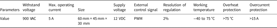

Fig. 9. The PCB and finished product of the self-developed 800 VAC power regulator.
4.3 Heating control algorithm
As mentioned in Section 3, the heating control algorithm running in the downhole control system mainly uses the power regulator and the temperature sensor to complete the on-off control and the power regulation of each heating element and the closed-loop temperature control for certain heating elements. After the development of the 800 VAC power regulator, the on-off control and the power regulation of the heating elements can be easily implemented; thus, the implementation details are not provided here.
Closed-loop temperature control is required for components that are easily damaged due to overheating, including the cartridge heaters in both thermal tips (maximum withstand temperature 800°C, ~50°C during drilling), the lateral heating strips (maximum withstand temperature 250°C, ~10°C during drilling) and the coaxial cable (maximum withstand temperature 100°C). The most vulnerable component is the coaxial cable inside the upper thermal tip. As shown in Figure 4a, given the proximity of the coaxial cable and upper thermal tip, the temperature of this contact area will be the same as that of the upper thermal tip. When the contact area is not immersed in water, e.g. when the probe emerges from ice-sheet surface during upward drilling, the temperature of the contact area will rise sharply, which may rapidly exceed 100°C, resulting in the cable breaking due to overheating. As the coaxial cable is the only medium connecting the RECAS-200 probe to the ice surface, if it breaks, the probe will drop and may be damaged or lost. Therefore, closed-loop temperature control for the contact area is essential during the upward drilling process.
The fuzzy PID control algorithm (Dequan and others, Reference Dequan, Guili, Zhiwei and Peng2012) has been widely used in the field of closed-loop temperature control of resistive heating elements. It was adopted in this study to implement the closed-loop temperature control of the upward thermal tip. The principle of the algorithm is shown in Figure 10. The algorithm sends the error e between the measured current temperature (MCT) and the preset temperature (PST) to the fuzzy PID module, and the control parameters k p, k i and k d are obtained by calculation. These control parameters will determine the adjustment of the heating of the upper thermal tip to continuously approach the PST.

Fig. 10. Principle of the fuzzy PID-based temperature control algorithm.
Using the fuzzy PID temperature control algorithm, real-time closed-loop temperature control of the upper thermal tip can be implemented. In the actual application of this algorithm, considering the following factors will allow the hysteresis effect of the temperature control to become relatively clear:
(1) When the upper thermal tip rises out of the ice surface, some of the heating elements will be completely exposed to the air, and heat dissipation conditions will become worse, resulting in a sharp increase in the rate of temperature rise;
(2) The temperature measurement system of the upper thermal tip is a single-point system, that is, the temperature of the whole copper body depends on the position of the temperature-sensing element, resulting in a certain temperature conduction delay;
(3) In the internal acquisition circuit of the temperature sensor, the ADC sampling rate is 12 MHz, and as the output temperature value is the median filtering result of five sampled values, this will introduce a certain acquisition delay;
(4) The RS-485 bus (transmission rate 9600 bps) is used to transmit data and control instructions between the temperature sensor and main control circuit, and there is a large transmission delay;
(5) When the main control circuit receives temperature sensor data through the universal asynchronous receiver–transmitter (UART) interface, a task scheduling delay will be introduced, due to the internal operation of the embedded operating system.
The hysteresis effect will cause the temperature rise curve to have significant nonlinearity. In extreme cases, even if the heating element is completely turned off, the temperature will still rise substantially. Therefore, there will be a larger overshoot in the algorithm. The definition of overshoot is 100%×(MCT max–PST)/PST, recorded as OVT. The OVT of the algorithm is set to 10% in this study.
From the structure diagram of the upper thermal tip (Fig. 4a), the temperature sensor is relatively distant from the contact area of the cable and the upper thermal tip. As a result, the MCT of the temperature sensor does not reflect the real-time temperature of the contact area (defined as CAT). From long-term actual measurements, CAT is ~15°C higher than MCT; thus, the temperature difference between CAT and MCT can be recorded as:

When setting the PST, △T and OVT must be considered. For example, if the CAT is to be limited to 95°C, the PST of the fuzzy PID algorithm should be calculated as:

Solving Eqn (2), PST = 72.73°C, then PST can be set to 70°C.
The closed-loop temperature control algorithm was mainly used to prevent the coaxial cable from being burnt during upward drilling, where it passes through the upper thermal tip. However, given that all the heating elements are attached with temperature sensors (as shown in Fig. 3), the temperature control algorithm can be extended to all the heating elements in the probe, which also provides the possibility for more accurate temperature control in the future.
5. Tests
After the production of the relevant modules of the gradient heating system, independent tests of each module should be conducted to test whether these meet the design requirements. The modules are then connected to the actual heating elements (two thermal tips and four lateral heating tubes) to complete a joint test of the overall heating control system.
5.1 Module tests
In the proposed heating control system, the individual modules include the downhole power supply system for separating the control power from the heating power, the 800 VAC small-sized solid-state power regulator and the heating control algorithm. The heating control algorithm runs in the control system; thus, it cannot be tested separately and can only be tested with the assistance of the control system during the joint test of the overall heating control system.
5.1.1 Heating power and control power separation test
The discussion in Section 4.1 identified that two key components were needed to achieve the separation of heating power and control power, that is, the heating element that worked with 800 VAC and a small number of step-down transformers. After obtaining these two components, we set up a module test environment, as shown in Figure 11, based on the structure of the RECAS-200 power supply system (Fig. 6), which not only verified the separation of heating power and control power, but also tested whether the newly developed 400 VAC cartridge heaters could perform in a stable fashion with 800 VAC, after being connected in series.

Fig. 11. Module test environment for separating heating power from control power.
In the setup illustrated in Figure 11, the step-up transformer was a customized 0–1200 VAC, adjustable, 30 kVA AC power cabinet, which directly integrated multiple measurement meters to simultaneously measure the input and output voltage and current. In the heating power part, the heating load was simulated by 16 newly developed cartridge heaters (400 VAC/540 W), which were connected in series, in pairs (i.e. they are divided into eight groups), and then connected in parallel to the output of the AC power cabinet. In this connection mode, the total voltage across any two cartridge heaters connected in series was 800 VAC. As this connection mode is also used by the cartridge heaters inside the thermal tip, it can make the test as close as possible to the actual working condition of the probe. The nominal power of the heating load reaches 8.64 kW. All the power regulators are removed and only the full power (100%) output is tested. In the power control part, three toroidal transformers with a single power of 700 W are used to perform power separation. The downhole AC-DC and DC-DC modules of RECAS-200 probe are connected to the rear end of the toroidal transformers to convert the stepped-down 220 VAC power to multiple sets of DC power (12 VDC, 24 VDC and 48 VDC). The load of the control power is simulated by several power resistors. The RECAS-200 power draw on the 12 and 24 V outputs is negligible and therefore not included in this test.
The test results are shown in Figure 11 and Table 5. During the test, the total output power of the high-voltage AC power cabinet is 9.268 kW. In the control power part, the total output power of three toroidal transformers is 1.138 kW, that is, the control power is 1.138 kW. Although the heating power is not directly measured, it can be calculated from the total output power minus the control power, which is 8.13 kW. During the test, the measurement results of the total power, heating power and control power are similar to the downhole power requirements in Table 2, indicating that both the separation strategy and the newly developed 400 VAC cartridge heaters passed the module test and satisfied the design criteria.
Table 5. Module test results for separating heating power and control power

5.1.2 800 VAC small-sized solid-state power regulator
A test environment as shown in Figure 12 is built to test and verify the functions and parameters of the self-developed 800 VAC power regulator. In the test environment, the DC power is used to replace the toroidal transformers and the module group composed of AC-DC and DC-DC to directly provide 12 VDC for the power regulator and the control system. To observe the power regulation effect, the heating load was supplied using four 220 V/800 W halogen lamps connected in series. The total power reached during the test was 2600 W, which was higher than the maximum power (2500 W) actually regulated by the single power regulator in RECAS-200. The electricity acquisition module is used to monitor the voltage and current effective value of the simulated heating load. The high-low temperature test chamber is used to test the working temperature range of the power regulator.

Fig. 12. Setup to test and verify the functions and parameters of the 800 VAC power regulator.
A photograph of the test process is shown in Figure 13a. During the test, the flashing cycle of the halogen lamp indicates whether the control cycle is normal. Through the oscilloscope, the output AC waveform of the power regulator (blue waveform in Fig. 13b) and the input AC waveform of the single-phase voltage regulator (yellow waveform in Fig. 13b) can be observed simultaneously. The power regulator performs an obvious cycle shutdown operation.

Fig. 13. (a) Actual test scene and (b) actual waveform of the 800 VAC solid-state power regulator.
Using the test environment shown in Figure 13, we also tested and verified the power regulation function of the power regulator. During the test, the full power value (100%) is set as the load power when the power regulator is fully turned on, and the power regulation resolution (2%) is used as the step unit to increase the power regulation ratio until 100%. The real control DC voltage converted by the PWM-to-DC circuit and the real power output of the load are measured at different power regulation ratios, as shown in Figure 14. The curve of the PWM-to-DC conversion is very smooth and has good continuity, but the linearity is poor (10.36%) due to the relatively large conversion error. The linearity is defined as the ratio between the maximum deviation (the real output curve and the expected output curve) and the full scale. A smaller ratio indicates a better linearity of the curve. Although the continuity of the real power output curve of the power regulator is poor, it is distributed around the expected output curve and has better linearity of 5.72%.

Fig. 14. Power regulation test curve of the 800 VAC power regulator: (a) output voltage of the PWM-to-DC vs regulation ratio; (b) output of the power regulator vs regulation ratio.
The results of the test and verification show that the self-developed 800 VAC small-sized solid-state power regulator meets the design parameters as shown in Table 4.
5.2 Joint test of heating control system
Following the independent tests of each module, we set up a joint test environment for the heating control system as shown in Figure 15.

Fig. 15. The joint test environment of the heating control system.
Eight 800 VAC power regulators (including the attached heat sink) are integrated into the control chamber. The heating loads are replaced with actual heating elements (two thermal tips and four lateral heating tubes). To verify the performance of the heating control system, the test is divided into two parts; on-off control and power regulation for all the heating elements and closed-loop temperature control of the upper thermal tip when drilling upward.
5.2.1 On-off control for all the heating elements based on the power regulators
As the power regulation function of the power regulator has passed the test (see Section 5.1.2), this is no longer required in the joint test. During the joint test, we used the two limit regulation ratios of the power regulator, that is, 0 and 100%, to perform on-off control tests for all heating elements.
During the test, the probe turns off all other functions and only turns on all heating elements. We first simulate the downward drilling process, manually turning on the lower thermal tip and all lateral heating tubes; then we simulate the upward drilling process, manually turning on the upper thermal top and all lateral heating tubes. During the test, we occasionally turn off all heating elements that are being heated and then turn them on again to verify the reliability of the on-off control. Simultaneously, we use the power parameter acquisition module in the control system to collect and record the voltage and current values of all heating elements in real-time. Through calculation, the power values consumed by all the heating elements can be obtained, and the statistical results of these power values over a representative period (~1 h) are summarized in Figure 16.

Fig. 16. Statistical results of the power consumed by all the heating elements over ~1 h. Variables t1–t10 represent test periods in which different heating element combinations were turned on. Among these, during t1, t3 and t7, only the lower thermal head was turned on for testing, whereas during t2, t5 and t8–t10, both the lower thermal head and four lateral tubes were turned on. During t4, all heating elements were turned on for testing, over a short period, whereas during t6, only the four lateral heating tubes were turned on.
From Figure 16, all heating elements can be controlled reliably through a self-developed 800 VAC solid-state power regulator. During both downward and upward drilling, the total heating power is controlled within 8.45 kW. Therefore, with eight self-developed solid-state power regulators, a variety of power output combinations of different heating elements is possible in the range of 0–11 kW.
5.2.2 Closed-loop temperature control of upper thermal tip
In the worst-case scenario, the upper thermal tip is exposed to the air in the actual upward drilling process. The closed-loop temperature control of the upper thermal tip is tested primarily for this worst case.
During the test, the upper thermal tip will be directly exposed to air. The heating control part uses two power regulators and adopts the fuzzy PID temperature control algorithm detailed in Section 4.3. During the operation of the fuzzy PID algorithm, we set the CPT to 95°C to simulate the actual situation. Then according to Eqn (2), the PST should be 70°C. During the test, the real-time recorded MCT value of the upper thermal tip indicates whether the overshoot OVT is strictly controlled within 10%.
After repeated tests, the fuzzy PID algorithm can run stably and control the overshoot temperature strictly within 5°C (the corresponding OVT does not exceed 8%), which meets the design requirements. The test results for two representative periods are shown in Figure 17. Figure 17 also shows the output heating power curve of the power regulator corresponding to the upper thermal tip. From Figure 17, the overall trend of the power curve is the opposite of the temperature curve, with obvious hysteresis.
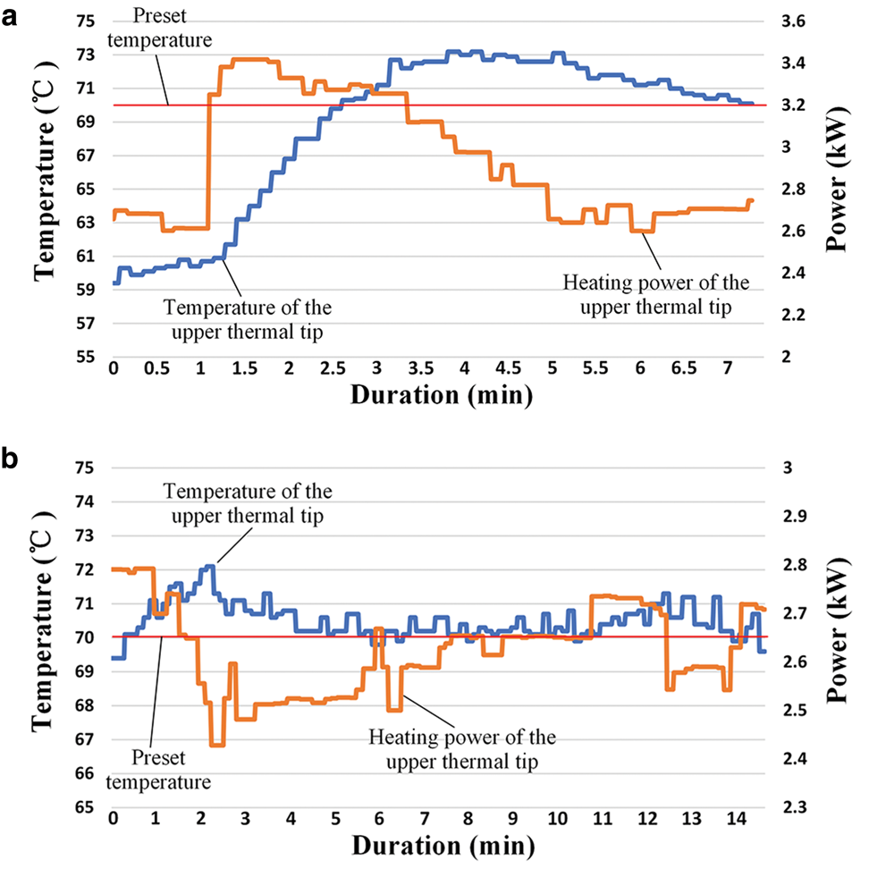
Fig. 17. Two representative results for the closed-loop temperature control test of the upper thermal tip. In the starting position of (a), the temperature of the upper thermal tip is much lower than the PST due to the initial low temperature of the upper thermal tip.
The results of the joint test show that the proposed heating control system meets all the design requirements, allowing for the introduction of the heating control system into the RECAS-200 probe.
6. Conclusions
In this study, a heating control system for RECAS-200 is proposed, which allows for separation of heating power and control power of the RECAS-200 probe, power regulation of all heating elements and closed-loop temperature control of components that are vulnerable to damage during overheating. To decrease the RECAS-200 total weight and thereby reduce the load-bearing requirements of the cable (and therefore its diameter), the use of the high-power voltage converter must be limited. To this end, separation of heating power and control power based on few low-power transformers is proposed. To avoid small output voltage of the commercial solid-state power regulator and the bulky size of the commercial thyristor controller, an 800 VAC small-sized solid-state power regulator is developed based on bidirectional thyristor and cycle regulation method to perform the power regulation of different heating elements. To prevent coaxial cable overheating during upward drilling, a fuzzy PID-based temperature control algorithm was introduced for closed-loop heating control. The results of independent module test and the joint test indicate that the proposed heating control system for RECAS-200 meets the design requirements and can be introduced into RECAS-200.
Acknowledgements
This work was supported in part by the National Key Research and Development Project of China (Grants No. 2016YFC1400302); the Key Research and Development Program of Zhejiang Province (Grants No. 2020C03098); the Public Welfare Technology Research Project of Zhejiang Province (Grants No. LGF21E090004); the Fundamental Research Funds for the Universities of Zhejiang Province (Grants No. GK199900299012-024, GK209907299001-001); and Zhejiang Provincial Key Lab of Equipment Electronics. We also thank Mikhail Sysoev for his help in preparing illustrations. We also thank all the reviewers that provided insightful comments on our work and helped us to improve the paper substantially.


 Open access