
Reliability Study of BEV Powertrain System and Its Components—A Case Study

1
Hunan Provincial Key Laboratory of Vehicle Power and Transmission System, Hunan Institute of Engineering, Xiangtan 411104, China
2
Technology Center of Xiangtan Electric Manufacturing Group, Xiangtan 411201, China
3
School of Humanities and Education, Hunan Vocational College of Electronic and Technology, Changsha 410217, China
*
Author to whom correspondence should be addressed.
Processes 2021, 9(5), 762; https://doi.org/10.3390/pr9050762
Submission received: 2 April 2021
/
Revised: 20 April 2021
/
Accepted: 25 April 2021
/
Published: 27 April 2021
(This article belongs to the Special Issue Clean Combustion and Emission in Vehicle Power System)
Abstract
:The powertrain system is critical to the reliability of a battery electric vehicle (BEV). However, the BEV powertrain is a complex system; it includes the motor, motor controller, power distribution unit, battery system, etc. The failure of any of these components may result in the failure of the entire powertrain system and eventually cause serious traffic accidents on the road. However, how much does each component affect the reliability of the entire system, and which components are the most vulnerable in the entire system? These questions are still unanswered today. To develop a reliability design for a BEV powertrain system, it is essential to conduct detailed research by investigating the most vulnerable component parts of the entire powertrain. In the present study, a fault-tree model of the entire powertrain and its subsystems was developed. Based on this model, the failure rates of all components were calculated first. Then, trends in the reliability indices for the entire powertrain and its components were estimated against BEV service life. From the estimation results, we learned that with increased service time, the reliability of the entire powertrain system is indeed much lower than that of its individual subsystems. Moreover, through comparative research, we found that the battery module is the most unreliable component not only of the battery system, but the entire powertrain system. Additionally, it was interesting to find that the reliability of the motor components was higher than that of other subsystem components, but that the reliability indices for the entire motor were not the highest among all the powertrain subsystems studied in this paper. We believe the findings of the present study will be of great significance to an improved understanding of the reliability design and maintenance of BEVs.
1. Introduction
As a means of reducing environmental emissions from the automotive industry, electric vehicles (EVs) have attracted increasing interest in recent years. Taking China as an example, about 5000 electric vehicles (EVs) were sold in 2011, but by the end of 2018, the total had reached 984,000, which was an increase of 50.8% over the previous year [1,2]. In addition, EVs are also very popular in other countries and regions around the world. According to a global electric vehicle outlook 2020 report released by the International Energy Agency (IEA), so far, 17 countries have announced a “100% zero emissions goal by 2050” to phase out internal combustion engine vehicles [3]. This means that there will be more and more BEVs running on the road [4,5]. However, despite the increasing interest in BEVs in recent years, their reliability, and particularly the reliability of their powertrains, are still a matter of concern today.
In order to improve the reliability of BEV powertrain systems, many related efforts have been made. For example, a reliability study of the battery system has been conducted [6] and a reliability-based design concept for Li-ion battery packs proposed [7], providing a way to improve the reliability of battery packs by optimizing the configuration of redundant cells. The reliability of different battery packs with different configurations and different numbers of battery cells was compared [8], and it was found that due to thermal disequilibrium effects, battery pack reliability does not increase monotonically as the number of redundant battery cells grows. In other studies [9,10], a multi-fault diagnostic method was proposed to improve the reliability of battery system operation; this method was further improved by adding a function to estimate the charging state of the battery pack [11]. In order to accurately assess the reliability of lithium-ion batteries, a reliability model considering the dependency among cells for the overall degradation of lithium-ion battery packs was built in [12]. Apart from these, the reliability of the stator and rotor components in permanent magnet synchronous motors for BEVs has been studied using a combined fault tree and Petri net approach [13,14]. The fault logic of failures caused by key components of the drive motor (i.e., stator and rotor windings and bearings) has also been investigated [15,16,17] using the approach of fault tree analysis (FTA); the results showed that different components have different effects on the reliability of the entire drive motor and also suggested that reliability issues in the drive motor and motor controller should be investigated together when assessing the reliability of the motor system; otherwise, an unreliable reliability prediction may be obtained. Given that electronic device lifetime determines the reliability of a BEV inverter to a large extent, the reliability of the insulated gate bipolar translator (IGBT) module has been predicted using the methods of the coffin-manson model and survey statistics [18,19,20]. The reliability of fuel cell electric vehicle (FCEV) power conditioners and their sub-systems has been investigated with the aid of FTA [21]. An investigation into the reliability of a single-motor drive system in a belt conveyor also has been investigated, providing a useful way to optimize drive system reliability, etc. [22].
There is no doubt that these research efforts will benefit reliability studies of powertrain systems. It should be noted that these reliability studies were mainly focused on powertrain components or subsystems and did not discuss issues from the perspective of an entire powertrain system. However, the powertrain systems in BEVs are very complex, consisting of multiple subsystems, such as the battery system, power distribution unit, motor controller, drive motor, etc. All these subsystems are required to work synchronously as a whole, and the failure of any one of them can cause the breakdown of the entire powertrain system. In addition, the structure, type, and characteristics of components or parts may also affect the reliability of the entire system to varying degrees. However, this issue has not been considered before. Hence, the purpose of this research was to fill these gaps in knowledge by looking into the reliability issues associated with BEV powertrain subassemblies, components, and subsystems. It is our hope that this study will provide useful reference experience and theoretical guidance to future efforts in the reliability design and aftersales maintenance of BEVs.
2. The Powertrain System in BEVs
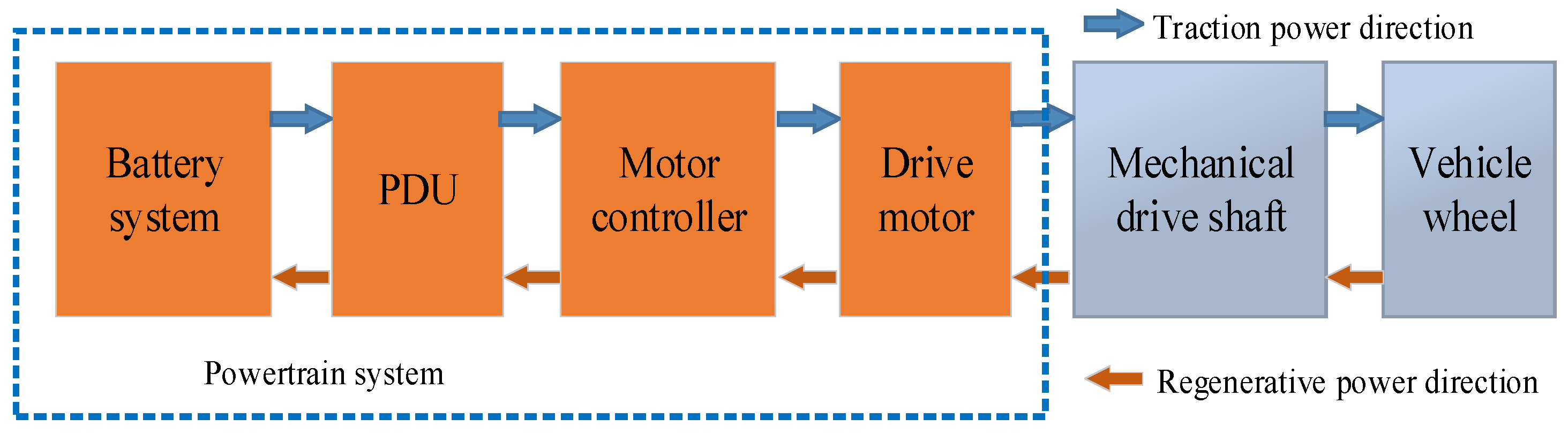
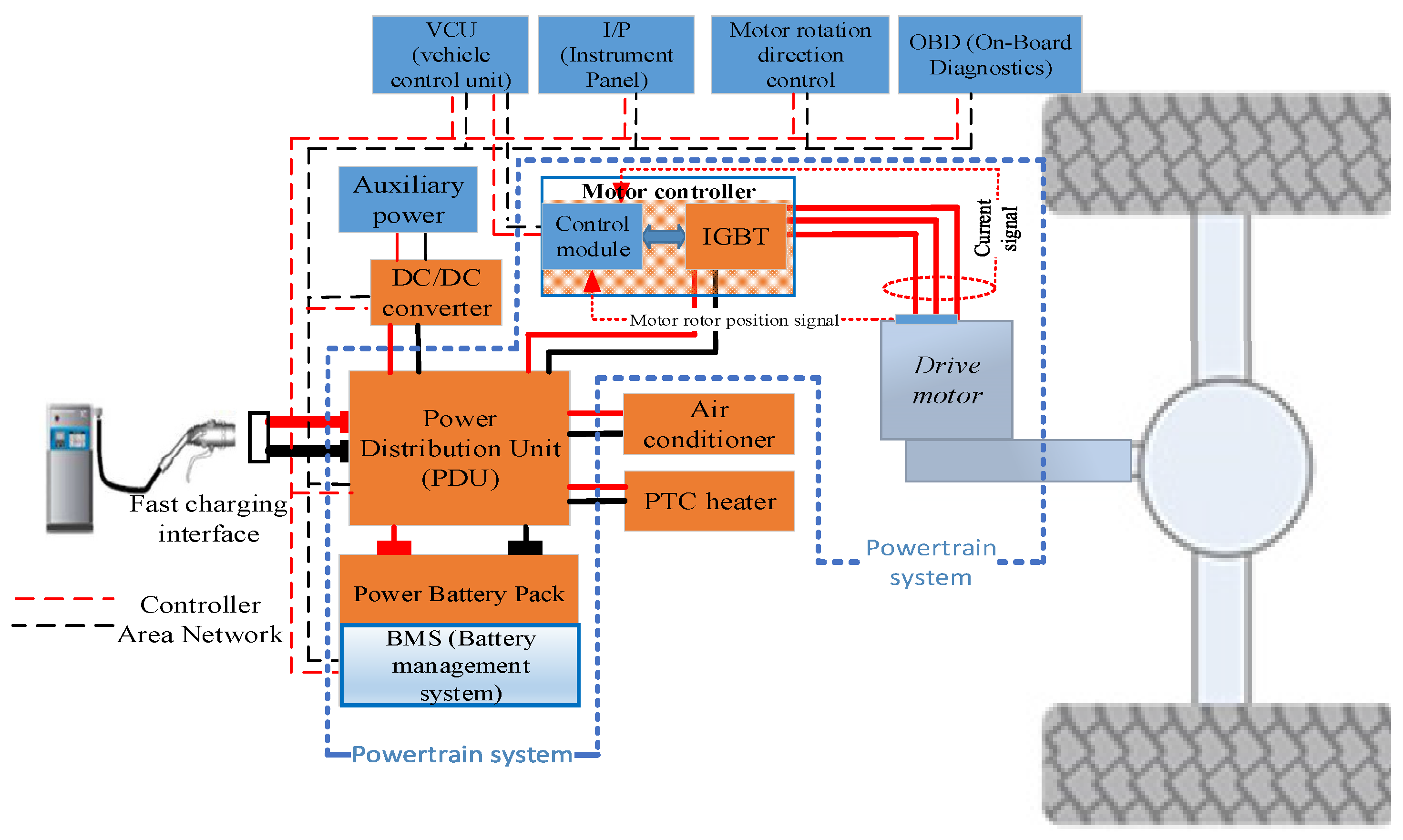
As the core system in a BEV, the powertrain system is similar to the engine and transmission system in a traditional diesel or petrol-fueled vehicle. However, in terms of energy conversion and power transmission, BEVs are different from traditional diesel or petrol vehicles. To facilitate an easier understanding, a schematic diagram of the energy and power transmission process in a BEV is shown in Figure 1. From the figure, we can see clearly that the powertrain system of a BEV mainly consists of a battery system, a power distribution unit (PDU), a motor controller, and a drive motor. When BEVs work normally, the electric energy stored in the battery system is first input into the PDU, then to the motor controller through the PDU. Finally, the electric energy is transformed to mechanical energy to operate the BEV by driving the motor system. Conversely, when BEVs brake or experience wheel slip, the feedback energy will be stored in the battery system through the powertrain system. In order to better understand the relationship between the BEV powertrain system structure and the logical connections with its subsystems, a structural diagram of a BEV powertrain system is shown in Figure 2. Briefly, the functions of the subsystems and components of the powertrain are described below.
The battery system is mainly used to store electrical energy and is composed of multiple battery cells connected in series and in parallel. Besides the battery cells, the battery system also includes a battery management system (BMS) controller, power electronic components, etc. The BMS controller is responsible for monitoring and managing the battery modules. It can measure the voltage, current, and temperature of individual battery cells. Based on these measured data, an appropriate control strategy is implemented to prevent abnormal conditions of the battery pack, such as over-discharging, overcharging, and overheating. The power electronic components handle the functions of protecting the battery cells from being damaged by excessive current, controlling the power-on and power-off operation of the electric system, and cutting off the power supply to the BEV powertrain in case of an emergency.
The PDU handles the functions of redistributing the power output from the battery system and providing interfaces for other systems or BEV components.
The motor controller is mainly used to control the drive motor, ensuring that it runs reliably and steadily, and transmit current working-status information on the drive system (i.e., motor and motor controller) to the vehicle controller in real time.
The drive motor is an energy conversion device [23]. It has two main functions: converting electrical energy into mechanical energy when the vehicle is driving, and then converting mechanical energy into electrical energy under braking or wheel-slipping conditions.
From the above description, we can understand that the powertrain system of a BEV is a complex system that consists of many components, the failure of any one of which may result in the failure of the entire powertrain system [24,25]. However, to what extent does each subsystem and its components affect the reliability of the entire system, and which components are the most vulnerable in the entire powertrain system? These questions are still unresolved today. To answer them, we conducted a detailed reliability study of the BEV powertrain.
3. Reliability Study of Powertrain System
As described above, the powertrain system in a BEV is composed of a battery system, PDU, motor controller, and drive motor, so, the following research on the reliability of the powertrain system was carried out in terms of these four aspects. It is worth noting that due to their housing shell, the components in a BEV powertrain are usually reliable and rarely damaged in operation and pose little risk of affecting the reliability of the entire system [26]. Therefore, the reliability of the housing shell was not considered in this study.
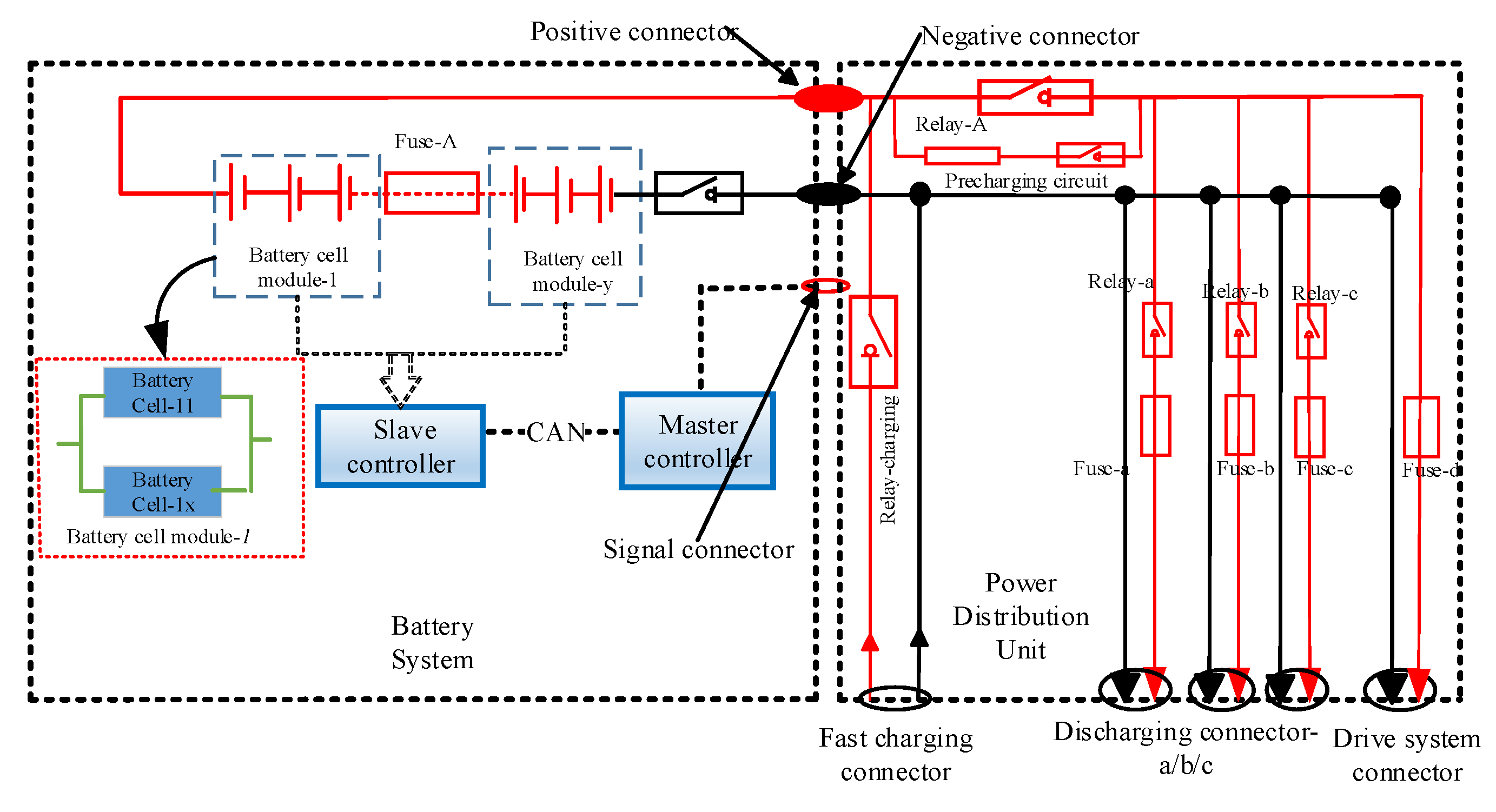
The schematic diagram of the battery system and PDU are shown in Figure 3. From the figure, we can see that the battery system is composed of a battery module and its related components, such as the BMS controller, fuse, relay, and signal detection devices, etc. The BMS controller consists of two parts (i.e., BMS master controller and BMS slave controller) [6]. Both the master controller and the slave controller are integrated circuit boards composed of printed circuit boards (PCBs) and surface mounted components (SMCs). The PDU is used to redistribute the power output from the battery system and provide interfaces for other systems or components in a BEV; it is mainly composed of relays, fuses, and connectors.
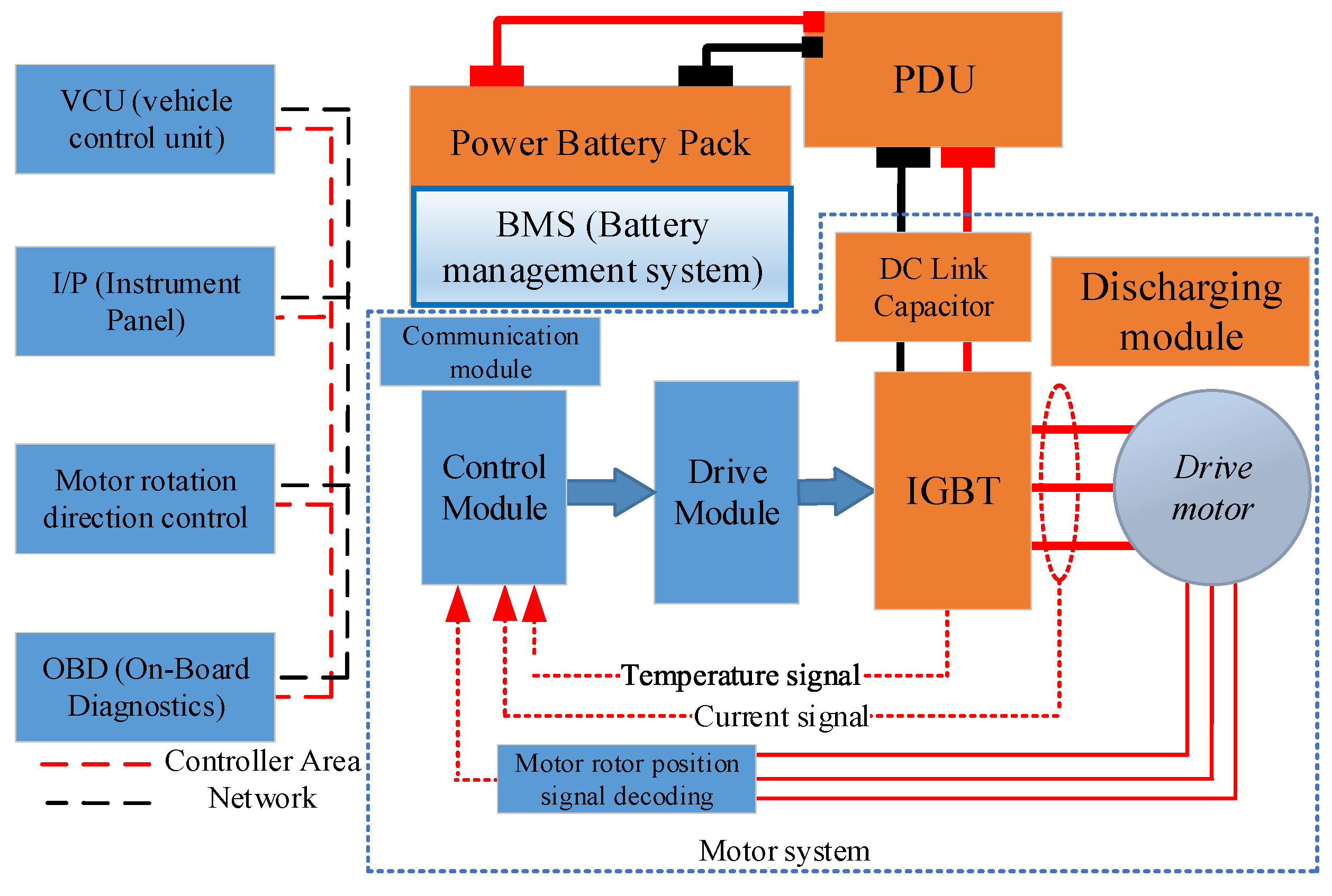
Similarly, a schematic diagram of the motor system is shown in Figure 4. In that figure, we can see that the motor controller is mainly composed of DC-link capacitors, copper busbars, the IGBT, and function modules (i.e., drive module, control module, communication module, and discharging module). In contrast, the drive motor is mainly composed of bearings, rotor, stator, sensors, and other associated components.
The modules of the motor controller are integrated circuit boards, which are mainly composed of PCBs and SMCs such as inductors, resistors, capacitors, transformers, integrated chips, diodes, etc. According to IEC TR62308-2004 [27], when evaluating the reliability of these components, they can be divided into two parts (i.e., PCB and SMCs), as show in Figure 5.
Based on the above detailed description of the powertrain system, a fault- tree model of the entire powertrain system is shown in Figure 6.
In this figure, “powertrain system failure” is defined as the top event. Failures of the battery system, PDU, motor controller, and drive motor are intermediate events (or logic gate events) of the entire model. gb1 to gb5, gc1 to gc5, and gm1 to gm4 are intermediate events of the powertrain subsystems, which are the logical combination of relevant basic events. All these events are explained in Table 1.
From Figure 6, we can see that the reliability of the powertrain system depends on the reliability of its subsystems (i.e., battery system, power distribution unit, motor controller, and drive motor), whereas the reliability of individual subsystems depends on the reliability of their respective components. Therefore, the failure rate of a powertrain system and its subsystems can be estimated by
where is the failure rate of the BEV powertrain system; to are the failure rates of the battery system, PDU, motor controller, and drive motor, respectively; to are the failure rates of battery system intermediate events; to are the failure rates of PDU components (or basic events); to are the failure rates of motor controller intermediate events; and to are the failure rates of motor controller intermediate events. Detailed explanations are listed in Table 1.
Likewise, the intermediate event failure rates of the battery system, motor controller, and drive motor can be expressed as
where to are the failure rates of battery system components (or battery system basic events); to are the failure rates of motor controller components (or motor controller basic events); and to are the failure rates of motor components (or motor basic events). Detailed explanations of all parameters and symbols in Formula (2) are listed in Table 1.
4. Case Study
Based on the aforementioned failure rate estimation methods, a case study was performed in this section in order to quantitatively assess the reliability of a powertrain and its components. The BEV of interest is shown in Figure 7, and the performance parameters of its powertrain are listed in Table 2.
4.1. Failure Rates of Powertrain Components
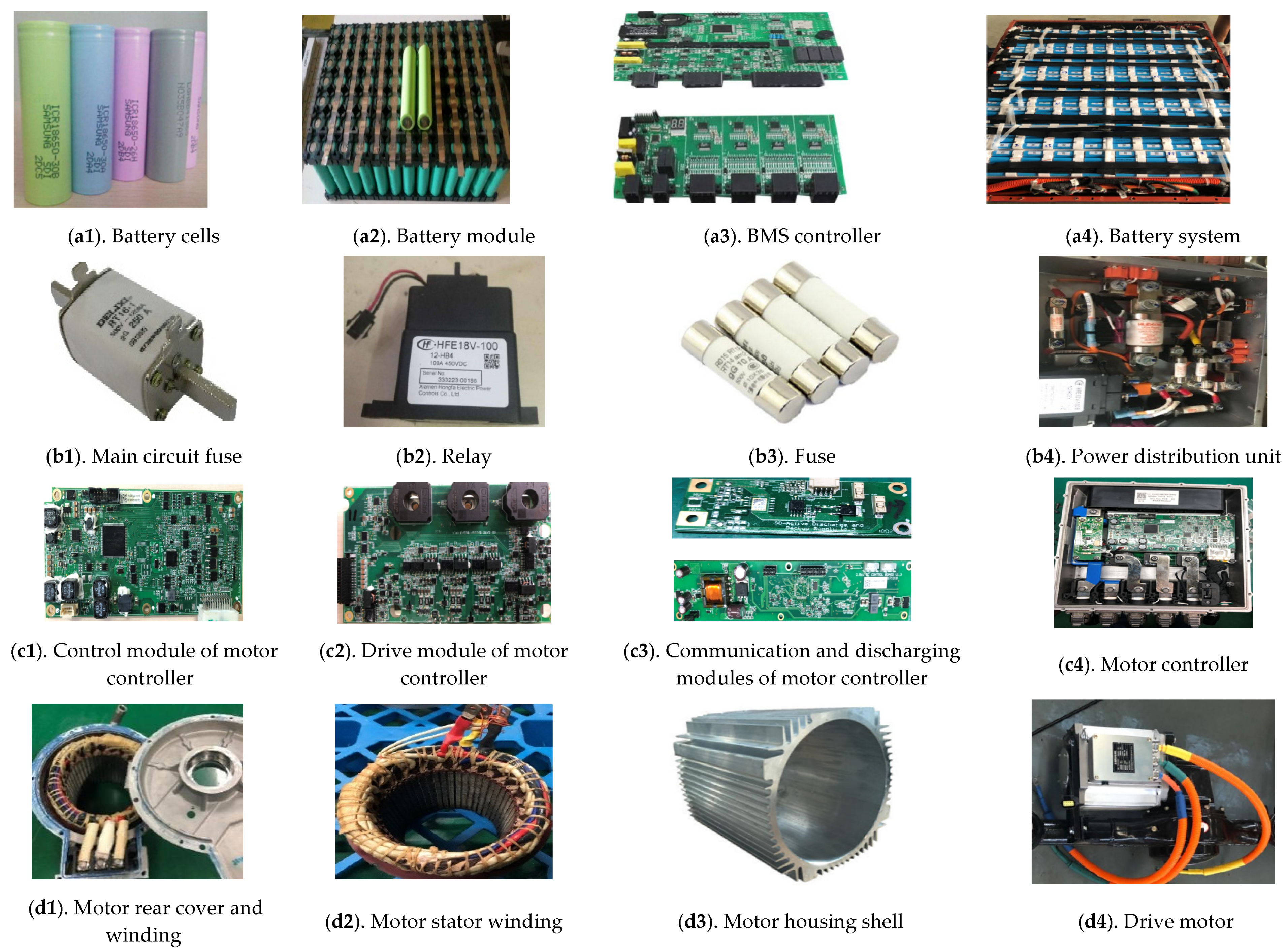
As mentioned earlier, the BEV powertrain system is composed of multiple subsystems (i.e., battery system, PDU, motor controller, and drive motor). The structures and parts of these subsystems are shown in Appendix A Figure A1. With help from manufacturer engineers, the model, specifications, and number of parts or components in the powertrain subsystem of this BEV have been listed in Appendix A Table A1. The types, specifications, and number of surface mounted components (SMCs) on the PCBs are listed in Appendix A Table A2. The PCB parameters of the motor controller and the BMS controller are listed in Appendix A Table A3. Hence, according to international standards IEC TR62308-2004 [27], FIDES guide-2009 [28], MIL-HDBK-217F [29], and NSWC-09 [30], the failure rates of all the components of the powertrain could be estimated with Formulas (1) and (2). The calculation results are listed in Table 3.
From Table 3, some interesting conclusions were obtained, as follows:
- (1)
- In the battery system, the failure rate of the battery module is the highest and can be as high as 3.453, followed by the BMS master controller and the BMS slave controller with failure rates of 1.70010 and 1.6324, respectively. Power electronic devices are relatively reliable in battery systems and have the lowest failure rate (of 0.9213).
- (2)
- The faults of the PDU are mainly caused by relays, fuses, and connectors. The failure rate of the fuse in this study is the highest, up to 0.75, followed by the relay with a failure rate of 0.187. By contrast, the connectors are free of faults and have the lowest failure rate in the PDU.
- (3)
- Among all the modules of the motor controller, the control module has the highest failure rate, as high as 1.884; conversely, the failure rate of the discharging module is the lowest, as low as 0.2815. The driver module, communication module, and other components also tend to develop faults in operation, but their failure rates vary in the range of 1.4948–0.282.
- (4)
- Drive motor failures are primarily caused by bearings, stators, rotor windings, etc. From the research results, it was found that the oil seal of the bearing is the most vulnerable part in the drive motor (failure rate of 0.4465), followed by the position sensor and rotor/stator windings; their failure rates change in the range of 0.0252–0.0375. The temperature sensor is also prone to fail in operation. By contrast, the spline and shaft are relatively more reliable.
- (5)
- From the perspective of the entire powertrain system, the battery module is the most vulnerable part (its failure rate is as high as 3.2), followed by the control module SMCs and drive module SMCs of the motor controller, which have failure rates of 1.6257 and 1.3907, respectively.
4.2. Reliability Assessment of Powertrain System
In order to gain a more comprehensive understanding of the reliability of the BEV powertrain, the reliability indices of the entire system and its components were evaluated in this section with the aid of the following formula [31]:
According to the calculation results in Table 3, we were able to derive the failure rate used to calculate the reliability of the BEV powertrain with the help of Formulas (1) and (2). The calculation results are listed in Table 4.
Substituting the parameters in Table 4 into Formula (3), reliability parameters were obtained for a power system operating over 12,000 h and 25,000 h, respectively (shown in Figure 8).
From Figure 8, we can see the following:
- (1)
- All the components and subsystems in the powertrain system will become more and more unreliable with increases in their service time, i.e., the longer their service time, the lower their reliability indices tend to be. This agrees very well with the research conclusions obtained from the failure rate calculation results in Table 3 and Table 4.
- (2)
- From the perspective of the entire powertrain system, the battery system is much less reliable than the other subsystems, followed by the motor controller and drive motor; by contrast, the PDU is relatively more reliable. For example, after the powertrain system has run continuously for 10,000 h, the reliability index of the battery system, PDU, motor controller, and drive motor are 0.396, 0.887, 0.549, and 0.824, respectively (shown in Figure 8e). The most important point is that regardless of service time, the calculation results for the reliability index of the entire powertrain system are much lower than the corresponding values for the reliability indices of other, single components. For example, after the powertrain system has run continuously for 125,000 h, its reliability is about one-third that of the battery system, and less than one-eighth that of the PDU. This further indicates that we should take into account all the components when evaluating the reliability of the powertrain system, because the failure of any single component in the powertrain can, to varying degrees, affect the reliability of the entire system.
- (3)
- Among the components of all subsystems of the BEV powertrain system, the battery module is the most unreliable component in the battery system, fuses are the most unreliable parts in the PDU, and the control module is the most unreliable component in the motor controller; their reliability indices are 0.396, 0.887, 0.549, and 0.824, respectively, after the powertrain system has run continuously for 250,000 h (shown in Figure 8a–d).
- (4)
- The battery module is the most unreliable component in not only the battery system, but the entire powertrain system; conversely, the connector is the most reliable component in the entire system.
5. Conclusions
In order to provide a more reliable and comprehensive understanding of the reliability of the entire powertrain system in BEVs, a detailed study of the reliability issues in all components of the powertrain system was described in this paper. According to the investigation reported above, the following conclusions can be drawn.
- The reliability of the powertrain system and its subsystems will decrease gradually as their time in service increases. However, the reliability of the powertrain system decreases faster than any of the subsystems. For example, after the powertrain system has run continuously for 125,000 h, its reliability is about one-third that of the battery system and less than one-eighth that of the PDU.
- From the view of the entire BEV powertrain system, the battery module is the most vulnerable part in not only the battery system, but the entire powertrain system (failure rate of 3.076), followed by the control module and drive module of the motor controller (failure rates of 2.234 and 1.741, respectively), the BMS master controller (failure rate of 1.701), and BMS slave controller (failure rate of 1.632). Among the subsystems in a BEV powertrain, the battery module is the most vulnerable part in the battery system; the fuse is the most vulnerable part in the PDU; the control module is the most vulnerable part in the motor controller; and the oil seal of the bearing is the most vulnerable part in the drive motor.
- The research results in this paper also suggest that, due to the finding that the battery system and motor controller were much more unreliable than other system components, more care should be paid in the future reliability design of BEV powertrain systems to foster improvements in the overall reliability of electric vehicles.
Author Contributions
Writing—original draft, Q.T.; conceptualization, methodology, software funding acquisition, X.S.; validation, G.Z.; formal analysis, J.W.; writing—review and editing, H.Y. All authors have read and agreed to the published version of the manuscript.
Funding
This research was funded by Research Foundation of Education Department of Hunan Province, China, grant number 18B384.
Institutional Review Board Statement
Not applicable.
Informed Consent Statement
Not applicable.
Data Availability Statement
The data presented in this study are available in the main text and Appendix A of the article.
Acknowledgments
The authors gratefully acknowledge the support from the Research Foundation of Education Department of Hunan Province, China (Grant No. 18B384) and the Hunan Province Science and Technology Innovation Program (Grant Nos. 2017XK2303).
Conflicts of Interest
The authors declare no conflict of interest.
Appendix A
Figure A1.
Components of subsystems in powertrain system.


Table A1.
Components or parts of subsystems in powertrain system.
| Component or Part | Model/Specification | Number | Part | Model/Specification | Number |
|---|---|---|---|---|---|
| Component or part of battery system | |||||
| Positive connector for main circuit | EVH1-F1ZK-M8A | 1 | Negative relay for main circuit | EV200 | 1 |
| Negative connector for main circuit | EVH1-F1ZK-M8B | 1 | Positive relay for main circuit | HFZ16V-50-900 | 1 |
| Signal connector for battery system | Amphenol12492 | 1 | Fuse for main circuit | MSD | 1 |
| Current sensor | PL-2/75 Mv 400 A | 1 | Signal connectors for battery cells | Amphenol-TP1 | 96 |
| Temperature sensor | NTC10K | 10 | Master controller of BMS | BCU0V3 | 1 |
| Voltage sensor | R34-7 | 1 | Slave controller of BMS | BMU1V1 | 1 |
| Fastening screw for battery module | M6 | 97 | Battery Cell | 18650 | 85S5P |
| Component or part of PDU | |||||
| Main circuit fuse | URSU5-250 | Positive relay for main circuit | HFE82 | 1 | |
| Positive connector for main circuit output | EVH1-F1ZK-M8A | 2 | Negative connector for main circuit | EVH1-F1ZK-M8B | 2 |
| Component or part of motor controller | |||||
| Control module | NA | 1 | Drive module | NA | 1 |
| Communication module | NA | 1 | Discharging module | NA | 1 |
| IGBT | FS400R07A3E3 | 1 | DC Link capacitor | C362H557K19802 | 1 |
| Current failure sensor | PL-2/75 mV 200 A | 2 | |||
| Component or part of drive motor | |||||
| Hexagonal socket head cap screw | M6 × 20-12.9- NiZn/M6 × 12-NiZn | 28 | O-rings | 104 × 2.65GB/T 3452.1 | 2 |
| Oil seal | TC 40 × 52 × 8 Fluorine rubber | 2 | Position sensor | TS2225N1994E102 | 1 |
| Elastic ring for shaft | GB/T 894.1 40 | 2 | Winding | Wire diameter-7 mm | 1 |
| Deep-groove ball bearing | 6206-2Z/C3, WT | 2 | Temperature sensor | PT1000 | 2 |
Table A2.
Parameters for PCB failure rate calculations.
| Name | Controller Module | Driver Module | Communication Module | Discharging Module | BMS Master Controller | BMS Slave Controller |
|---|---|---|---|---|---|---|
| PCB layer coefficient | 1.4 | 1.4 | 1 | 1 | 1.4 | 1.4 |
| PCB layers | 4 | 4 | 1 | 1 | 4 | 4 |
| Track width of PCB | 0.23 | 0.6 | 0.35 | 0.6 | 0.35 | 0.35 |
| Track width factor of PCB | 3 | 1 | 2 | 1 | 2 | 2 |
| Number of SMCs | 553 | 368 | 38 | 24 | 386 | 463 |
| Number of THCs | 0 | 0 | 0 | 4 | 4 | 4 |
| Surface area of PCB | 104 | 104 | 25 | 23 | 154 | 160 |
Table A3.
Type, failure rates, and number of SMCs on PCB.
| Components | Type of Package | Single Device Failure Rate/FPMH | Number of SMCs on Controller Module | Number of SMCs on Driver Module | Number of SMCs on Communication Module | Number of SMCs on Discharging Module | BMS Master Controller | BMS Slave Controller |
|---|---|---|---|---|---|---|---|---|
| Capacitor | 0603-C/RB.3.6 | 0.00306/0.065 | 235 | 136 | 9 | 4 | 146 | 87 |
| Diode | SOD/SOT | 0.00554 | 49 | 64 | 5 | 3 | 19 | 21 |
| Op-amp chip | TSSOP | 0.01263 | 14 | 4 | 0 | 0 | 2 | 4 |
| Inductance | MSS | 0.06762 | 20 | 21 | 8 | 2 | 3 | 3 |
| MOSFET | SOT/DPAK | 0.059700 | 11 | 11 | 2 | 0 | 8 | 5 |
| Resistance | 0603-R | 0.00018 | 223 | 123 | 13 | 10 | 156 | 98 |
| Master chip | LQFP144 | 0.30950 | 1 | 0 | 0 | 0 | 1 | 1 |
| Optocoupler | SO8 | 0.08100 | 0 | 3 | 0 | 0 | 4 | 8 |
| Transformer | CEER117 | 0.013100 | 0 | 6 | 0 | 1 | 0 | 0 |
| Power MOSFET | D-PAK | 0.07500 | 0 | 0 | 0 | 4 | 0 | 0 |
| Communication chip | TSSOP | 0.12600 | 0 | 0 | 1 | 0 | 2 | 4 |
References
- Shi, S.; Zhang, H.; Yang, W.; Zhang, Q.; Wang, X. A life-cycle assessment of battery electric and internal combustion engine vehicles: A case in Hebei Province, China. J. Clean. Prod. 2018, 228, 606–618. [Google Scholar] [CrossRef]
- Suganya, S.; Raja, S.C.; Venkatesh, P. Simultaneous coordination of distinct plug-in Hybrid Electric Vehicle charging stations: A modified Particle Swarm Optimization approach. Energy 2017, 138, 92–102. [Google Scholar] [CrossRef]
- China Association of Automobile Manufacture. Current Status of the Electric Vehicle Industry. 2019. Available online: http://www.caam.org.cn.22 (accessed on 20 January 2019).
- China Electric Vehicle Research Alliance. 2019. Available online: http://biz.touchev.com/industry_data.24 (accessed on 15 May 2019).
- China Electric Vehicle Resources Network. Electric Vehicle Sales. 2019. Available online: http://www.evpartner.com/ZYC/.23 (accessed on 20 January 2019).
- Shu, X.; Yang, W.; Guo, Y.; Wei, K.; Qin, B.; Zhu, G. A reliability study of electric vehicle battery from the perspective of power supply system. J. Power Sources 2020, 451, 1–11. [Google Scholar] [CrossRef]
- Liu, Z.; Tan, C.; Leng, F. A reliability-based design concept for lithium-ion battery pack in electric vehicles. Reliab. Eng. Syst. Saf. 2015, 134, 169–177. [Google Scholar] [CrossRef]
- Xia, Q.; Wang, Z.; Ren, Y.; Sun, B.; Yang, D.; Feng, Q. A reliability design method for a lithium-ion battery pack considering the thermal disequilibrium in electric vehicles. J. Power Sources 2018, 386, 10–20. [Google Scholar] [CrossRef]
- Kang, Y.; Duan, B.; Zhou, Z.; Shang, Y.; Zhang, C. A multi-fault diagnostic method based on an interleaved voltage measurement topology for series connected battery packs. J. Power Sources 2019, 417, 132–144. [Google Scholar] [CrossRef]
- Xia, B.; Mi, C. A fault-tolerant voltage measurement method for series connected battery packs. J. Power Sources 2016, 308, 83–96. [Google Scholar] [CrossRef]
- Zhang, X.; Wang, Y.; Yang, D.; Chen, Z. An on-line estimation of battery pack parameters and state-of-charge using dual filters based on pack model. Energy 2016, 115, 219–229. [Google Scholar] [CrossRef]
- Wang, L.; Sun, Y.; Wang, X.; Wang, Z.; Zhao, X. Reliability Modeling Method for Lithium-ion Battery Packs Considering the Dependency of Cell Degradations Based on a Regression Model and Copulas. Materials 2019, 12, 1054. [Google Scholar] [CrossRef] [Green Version]
- Wang, B.; Tian, G.; Liang, Y.; Qiang, T. Reliability modeling and evaluation of electric vehicle motor by using fault tree and extended stochastic petri nets. J. Appl. Math. 2014. [Google Scholar] [CrossRef] [Green Version]
- Wang, B.; Liang, Y.; Yang, C.; Sang, Z. Reliability modeling and assessment of electric vehicle motor using fault tree and Fuzzy Petri Nets. Int. J. Grid Distrib. Comput. 2016, 9, 121–136. [Google Scholar] [CrossRef]
- Zhu, X.H.; Cui, S.M.; Shi, N.; Min, Y.L. Grey prediction model of motor reliability of electric vehicle. Electr. Mach. Control. 2012, 16, 42–46. [Google Scholar]
- Shu, X.; Guo, Y.; Yang, W.; Wei, K.; Zhu, Y.; Zou, H. A detailed reliability study of the motor System in pure electric vans by the approach of fault tree analysis. IEEE Access 2019, 8, 5295–5307. [Google Scholar] [CrossRef]
- Nordelöf, A.; Grunditz, E.; Lundmark, S.; Tillman, A.M.; Alatalo, M.; Thiringer, T. Life cycle assessment of permanent mag-net electric traction motors. Transp. Res. Part D 2019, 67, 263–274. [Google Scholar] [CrossRef]
- Song, Y.; Wang, B. Survey on reliability of power electronic systems. IEEE Trans. Power Electron. 2013, 28, 591–604. [Google Scholar] [CrossRef]
- Liu, H.; Shi, E.; Wang, W. Reliability analysis of the optimized Y-source inverter with clamping circuit. Microelectron. Reliab. 2019, 100, 113420. [Google Scholar] [CrossRef]
- Setoya, T.; Ogura, T.; Saito, W.; Matsudai, T.; Endo, K. Destruction failure analysis and international reliability test standard for power devices. Microelectron. Reliab. 2015, 55, 1932–1937. [Google Scholar] [CrossRef]
- Bahrebar, S.; Zhou, D.; Rastayesh, S.; Wang, H.; Blaabjerg, F. Reliability assessment of power conditioner considering maintenance in a PEM fuel cell system. Microelectron. Reliab. 2018, 88–90, 1177–1182. [Google Scholar] [CrossRef]
- Štatkić, S.; Jeftenić, I.B.; Bebić, M.Z.; Milkić, Ž.; Jović, S. Reliability assessment of the single motor drive of the belt conveyor on Drmno open-pit mine. Int. J. Electr. Power Energy Syst. 2019, 113, 393–402. [Google Scholar] [CrossRef]
- Jokanović, B.; Bebić, M.; Kartalović, N. The influence of combined strain and constructive solutions for stator insulation of rotating electrical machines on duration of their reliable exploitation. Int. J. Electr. Power Energy Syst. 2019. [Google Scholar] [CrossRef]
- Shu, X.; Guo, Y.; Yang, H.; Wei, K. Reliability Study of Motor Controller in Electric Vehicle by the Approach of Fault Tree Analysis. Eng. Fail. Anal. 2021, 121, 105165. [Google Scholar] [CrossRef]
- Khalilzadeh, M.; Fereidunian, A. A Markovian approach applied to reliability modeling of bidirectional DC-DC converters used in PHEVs and smart grids. Iran. J. Electr. Electron. Eng. 2016, 4, 301–313. [Google Scholar]
- Wang, L.; Liao, A.; Ding, Y. Reliability evaluation of rolling bearings for traction motors of bogies based on proportional hazards model. Meas. Control Technol. 2018, 31, 14–19. [Google Scholar]
- IEC TR62308-2004. Reliability Date Handbook-Universal Model for Reliability Prediction of Electronic-Components, PCBs and Equipment; International Electro Technical Commission: Geneva, Switzerland, 2004. [Google Scholar]
- FIDES Guide 2009 Edition A. Reliability Methodology for Electronic Systems. 2009. Available online: https://www.itemsoft.com/iqt_fides.html (accessed on 24 April 2021).
- MIL-HDBK-217F. Military Handbook: Reliability Prediction of Electronic Equipment. 1990. Available online: https://www.quanterion.com/wp-content/uploads/2014/09/MIL-HDBK-217F.pdf (accessed on 4 April 2019).
- NSW-2009. Handbook of Reliability Prediction Procedures for Mechanical Equipment. In Naval Surface Warfare Center Carderock Division; Naval Surface Warfare Center: West Bethesda, MD, USA, 2009. [Google Scholar]
- Essayed, E.A. Reliability Engineering, 2nd ed.; Publishing Housing of Electronics Industry: Beijing, China, 2012; pp. 99–104. [Google Scholar]
Figure 1.
Schematic diagram of energy and power transmission process of BEVs.

Figure 2.
Structural diagram of powertrain system in a BEV.

Figure 3.
Schematic diagram of the battery system and PDU.

Figure 4.
Schematic diagram of the motor system.

Figure 5.
Modules and components of the motor controller.

Figure 6.
Fault tree model of BEV powertrain system.

Figure 7.
BEV powertrain system and its subsystem

Figure 8.
Reliability indices of powertrain system.

Table 1.
Failure events of powertrain system.
| Intermediate Event | Code | Failure Rate | Basic Event | Code | Failure Rate |
|---|---|---|---|---|---|
| Battery system failure (S1) | |||||
| Failure of battery module | gb1 | Failure of signal connector for battery system | eb1 | ||
| Failure of battery cells | eb2 | ||||
| Failure of signal connectors for battery cells module | eb3 | ||||
| Failure of master controller of BMS | gb2 | Failure of PCB for master controller | eb4 | ||
| Failure of SMCs for master controller | eb5 | ||||
| Failure of slave controller of BMS | gb3 | Failure of PCB for slave controller | eb6 | ||
| Failure of SMCs for slave controller | eb7 | ||||
| Failure of power electronic device | gb4 | Failure of fuse for main circuit | eb8 | ||
| Failure of relay for main circuit | eb9 | ||||
| Failure of sensors | gb5 | Failure of current sensor | eb10 | ||
| Failure of voltage sensor | eb11 | ||||
| Failure of temperature sensor | eb12 | ||||
| Power distribution unit failure (S2) | |||||
| Power distribution unit failure (S2) | Failure of relay | ep1 | |||
| Failure of fuse | ep2 | ||||
| Failure of connector | ep3 | ||||
| Motor controller failure (S3) | |||||
| Failure of control module | gc1 | PCB failure of control module | ec1 | ||
| SMCs failure of control module | ec2 | ||||
| Failure of driver module | gc2 | Failure of driver module PCB | ec3 | ||
| Failure of driver module SMCs | ec4 | ||||
| Failure of discharging module | gc3 | Failure of discharging module PCB | ec5 | ||
| Failure of discharging module SMCs | ec6 | ||||
| Failure of communication module | gc4 | Failure of communication module PCB | ec7 | ||
| Failure of communication module SMC | ec8 | ||||
| Failure of other controller components | gc5 | DC link capacitor failure | ec9 | ||
| IGBT failure | ec10 | ||||
| Failure of drive motor (S4) | |||||
| Rotor failure | gm1 | Failure of rotor armature winding | em1 | ||
| Failure of rotor shaft | em2 | ||||
| Stator failure | gm2 | Failure of stator winding | em3 | ||
| Failure of stator core | em4 | ||||
| Transducer failure | gm3 | Failure of temperature sensor | em5 | ||
| Failure of position sensor | em6 | ||||
| Failure of other motor components | gm4 | Failure of spline | em7 | ||
| Failure of bearing oil seal | em8 | ||||
| Failure of bearing | em9 | ||||
Table 2.
Performance parameters of BEV powertrain system.
| Items | Parameters | Items | Parameters |
|---|---|---|---|
| Motor type | Asynchronous induction | Controller capacity | 70 KVA |
| Maximum output power | 35 kW | Maximum working voltage | DC450 V |
| Maximum speed | 9000 rpm | Frequency range | 0~600 Hz |
| Peak torque | 150 Nm | Peak point current | 250 A |
| Nominal voltage | AC227 V | Controller nominal voltage | DC320 V |
| Nominal voltage of cell (V) | 3.68 | The number of total battery cells connected in parallel in battery system | 5 |
| Operating voltage range of cell (V) | 2.9–4.0 | Nominal voltage of battery system | 312.8 V |
| The number of total battery cells connected in series in battery system | 85 | Total energy of battery pack | 25.9 kwh |
| Continuous charging current | 1.5 C | Continuous discharge current | 1 C |
| Protection level | IP67 | Auxiliary voltage | 9–36 V |
Table 3.
Failure rates of subsystem components in powertrain.
| Components | Code | Failure Rate λ/FPMH | Sub-Components or Parts | Code | Failure Rate λ/FPMH |
|---|---|---|---|---|---|
| Battery system | |||||
| Battery module | gb1 | 3.453 | Signal connector for battery system | eb1 | 0.1757 |
| Battery cells module | eb2 | 3.2000 | |||
| Signal connectors for battery cells module | eb3 | 0.0768 | |||
| Master controller of BMS | gb2 | 1.7010 | PCB of master controller for BMS | eb4 | 0.3567 |
| SMCs of master controller for BMS | eb5 | 1.3443 | |||
| Slave controller of BMS | gb3 | 1.6324 | PCB of slave controller for BMS | eb6 | 0.3356 |
| SMCs of slave controller for BMS | eb7 | 1.2968 | |||
| Power electronic device | gb4 | 0.9213 | Fuse of main circuit (i.e., Fuse A) | eb8 | 0.7600 |
| Relay of main circuit (i.e., Relay B) | eb9 | 0.1613 | |||
| Sensors | gb5 | 1.544 | Current sensor | eb10 | 0.6450 |
| Voltage sensor | eb11 | 0.6350 | |||
| Temperature sensor | eb12 | 0.2640 | |||
| Power Distribution Unit | |||||
| Relay | ep1 | ||||
| Fuse | ep2 | ||||
| Connector | ep3 | 0.0172 | |||
| Motor controller | |||||
| Control module | gc1 | 1.888 | PCB of control module | ec1 | 0.2357 |
| SMCs of control module | ec2 | 1.6527 | |||
| Driver module | gc2 | 1.495 | PCB of driver module | ec3 | 0.1041 |
| SMCs of driver module | ec4 | 1.3907 | |||
| Discharging module | gc3 | 0.282 | PCB of discharging module | ec5 | 0.0053 |
| SMCs of discharging module | ec6 | 0.2762 | |||
| Communication module | gc4 | 0.341 | PCB of communication module | ec7 | 0.0086 |
| SMCs of communication module | ec8 | 0.3319 | |||
| Other controller components | gc5 | 0.516 | DC link capacitor | ec9 | 0.0510 |
| IGBT*3 | ec10 | 0.4650 | |||
| Drive motor | |||||
| Rotor | gm1 | 0.300 | Rotor armature winding | em1 | 0.2772 |
| Rotor shaft | em2 | 0.0226 | |||
| Stator | gm2 | 0.252 | Stator winding | em3 | 0.2520 |
| Stator core | em4 | 0.0003 | |||
| Transducer | gm3 | 0.258 | Temperature sensor | em5 | 0.2195 |
| Position sensor | em6 | 0.0375 | |||
| Other motor components | gm4 | 0.568 | Spline | em7 | 0.0385 |
| Bearing oil seal | em8 | 0.4465 | |||
| Bearing | em9 | 0.0830 | |||
Table 4.
Failure rates of powertrain system and its sub-systems.
| Subsystem of Powertrain | Code | Subsystem of Powertrain | Code | ||
|---|---|---|---|---|---|
| Battery system | S1 | Drive motor | S3 | 5.990 | |
| PDU | S2 | 0.954 | Motor controller | S4 | 1.715 |
| Powertrain system | S | 17.910 |
Publisher’s Note: MDPI stays neutral with regard to jurisdictional claims in published maps and institutional affiliations. |
© 2021 by the authors. Licensee MDPI, Basel, Switzerland. This article is an open access article distributed under the terms and conditions of the Creative Commons Attribution (CC BY) license (https://creativecommons.org/licenses/by/4.0/).
Share and Cite
MDPI and ACS Style
Tang, Q.; Shu, X.; Zhu, G.; Wang, J.; Yang, H. Reliability Study of BEV Powertrain System and Its Components—A Case Study. Processes 2021, 9, 762. https://doi.org/10.3390/pr9050762
AMA Style
Tang Q, Shu X, Zhu G, Wang J, Yang H. Reliability Study of BEV Powertrain System and Its Components—A Case Study. Processes. 2021; 9(5):762. https://doi.org/10.3390/pr9050762
Chicago/Turabian StyleTang, Qian, Xiong Shu, Guanghui Zhu, Jiande Wang, and Huan Yang. 2021. "Reliability Study of BEV Powertrain System and Its Components—A Case Study" Processes 9, no. 5: 762. https://doi.org/10.3390/pr9050762
Note that from the first issue of 2016, this journal uses article numbers instead of page numbers. See further details here.