
Abstract
Photocatalysis method for environmental applications has been using for a long time. This review article traces back the origin of catalysis, its classification and journey of development to heterogeneous photocatalysis and the article's novelty is in the simplicity, and easily understandable language, designed for the beginners. These heterogeneous photocatalysts are grouped into eleven different categories. As the paper is focused on photocatalysis, an insight on fundamental principles and mechanisms of photocatalysis are explained systematically with schematic illustrations and reactions that take place during redox- oxidation and reduction reactions in photocatalysis. With an approach towards utilizing green energy and expanding the photocatalyst' absorption wavelength range towards the visible regime, bandgap engineering techniques by adopting doping and hetero-structures are explained with examples of different materials. In addition, dominating factors of photocatalysis reaction viz. composition of a heterogeneous photocatalyst, doping, hetero-structures, pH, surface defects on photocatalysis reaction are explored, focussing on variable charge transfer mechanisms. The main influencing factor in generating reactive oxygen species is pH of the photocatalysis reaction and are studied indetail. The effect of alkalinity or acidity in catalyst surfaces and molecular interaction depending upon the point zero charges of the photocatalyst are discussed. For the better study of catalyst properties, careful analysis and study is a much-needed field as a scope for further improvement. Hence, this article will guide a beginner to understand the photocatalysis topic with ease.
Export citation and abstract BibTeX RIS

Original content from this work may be used under the terms of the Creative Commons Attribution 4.0 licence. Any further distribution of this work must maintain attribution to the author(s) and the title of the work, journal citation and DOI.
Introduction
In today's millennium, the demand for catalyst material is soaring sky high for its crucial importance and contribution. It is eminently impossible to picture a world without a catalyst for its tremendous involvements in many industries, material decompositions, chemical reactions, fuel generations, and we, human beings are run by catalyst activities called enzymes. Due to limited resources of fossil fuels obtainable worldwide, catalyst materials have been playing a major role in minimising the energy consumption in the processes of converting inputs to outputs easily, efficiently and effectively by using catalyst materials. Some remarkable applications of photocatalyst include water splitting, [1] conversion of solar energy into light using photovoltaics/solar cells, [2] transforming green-house gases (GHGs) into reusable fuels like CO2 to methanol, [3] water treatment and purification, [4] photochromic glasses, [5] generation of green fuels, [6] self-cleaning glasses, [7] GHGs capturing cement, [8] hydrogen gas production, [9] and so forth [10, 11]. Therefore, due to the increasing rate of pollution of water/air/food etc., the use of advanced catalyst nanomaterial to mitigate problems are becoming a focal point in this 21st century. The exploration of catalyst materials and methods or activities to improve existing catalytic mechanisms have been attracting major attention but believed to be grown into maturation (in lab-scale implementations). Some desirable properties of photocatalyst nanomaterials are high selectivity, easy separation, mass production, recyclability, solubility, applicability in large scale, desirable reaction conditions, stability, cost-effectiveness, bio-compatibility, reproducibility, etc. which assist in evolving low-grade catalyst to highly efficient hybrid catalyst. Among these, researchers focus on the four most important aspects: activity, selectivity, stability, and toxicity. As an approach for hybrid photocatalyst, enzymes/homogeneous catalyst is anchored to the heterogeneous catalyst, giving a unified advantage of the high selectivity of homogeneous/enzymes catalyst and easily retractable capability of heterogeneous nature [12]. These photocatalysts are tuned and optimized by different approaches like designing synthesis routes, nanoparticle morphologies, defect engineering, elemental doping, framing heterostructures, customizing bandgap etc. These catalysts are triggered for the reaction by various external forces like: electromagnetic waves (UV/sunlight/visible light)—photocatalysis, [13, 14] electric field—electrocatalysis, [1, 15] sound—sonocatalysis, [16, 17] a combination of light and electric field—photoelectrocatalysis, [18, 19] heat—thermocatalysis, [20, 21] and so forth [22] as a main source of energy. Based on simplicity and efficiency, catalysis reaction activated by light, photocatalysis is one of the easiest, facile and widely used technique. This process is also used to analyse molecular or atomic-light interactions, catalytic reaction processes and chemical kinetics. Therefore, from the past decades, the efforts and focuses of the researchers have been shifted from developing new photocatalyst into understanding photocatalytic reaction dynamics extensively to increase efficiency for the existing materials for large-scale commercial applications.
The analysis of the mechanisms behind different catalytic reactions and material-material/material-activator interactions are becoming a scientific hub. Hence, the main objective of this review article is to discuss thoroughly the advances and developments in the field of heterogeneous photocatalysis. This review article also focusses on the modus operandi and up-gradation in the photocatalyst performance via different alterations in semiconductor heterogeneous photocatalyst, starting from elementary conventional semiconductor oxides like TiO2 and ZnO to coupled hybrid photocatalyst. The fundamental photocatalysis mechanisms, catalyst properties and its implementations toward environmental applications are elucidated for the better understanding, especially to the beginners. As photocatalysis is based on advanced oxidation process, the light-matter interaction for the production of reactive oxygen species (ROS) plays the role of the foundation for photocatalysis in combating pollutants. This paper tries to demonstrate all about photocatalysis in a simple language and manner with appropriate reactions and illustrations, taking dye pollutants degradation as a template. Also, as an approach to modify and enhance photocatalysis reaction rate, different strategies like bandgap engineering techniques, doping, and coupling with dissimilar elements/compounds making hybrid photocatalyst are reviewed in brief. The review will be based on the principles of light absorption enhancement, charge separation and their contribution to the photocatalytic efficiency. The effect of pH of the pollutant containing reaction medium on the photocatalysis process is explained in the latter part of the paper.
On the genesis of catalysis
The use of catalyst materials have started without our knowledge but consciously the concept appeared when a catalyst was used in the fermentation method to produce alcohol from sugar. And the report of using first known inorganic catalysts was reported in the year of 1552 by Valerius Cordus, using H2SO4 for increasing catalytic conversion rate [23, 24]. Figure 1 shows the illustration of the journey of a catalyst from an infant stage to its maturation and application stage. The catalysis reactions are broadly categorised into three types, homogeneous, heterogeneous or surface catalysis, and biocatalysis or enzymatic catalysis. Apart from these categories, catalysis may fall under environmental catalysis and hybrid/composite catalysis.
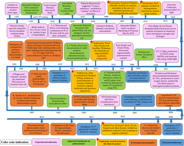
Figure 1. Illustrates the historical background in the chronological order of the advancement in catalysis and its related field [1, 23–46].
Download figure:
Standard image High-resolution imageHomogeneous catalysis reactions take place entirely in the same or uniform phase with the catalyst, whereas heterogeneous catalysis reactions take place at different phases like the solid-liquid, solid-gas interface. Unlike homogeneous catalysis that is single-sited comprising of catalytically active atoms, the heterogeneous catalyst has a well-defined structure, and the reaction is multi-sited where various active sites like edge, defect, face, etc. are involved simultaneously [47]. Enzymatic catalysis is outstanding because of its high catalytic potential (highly selective and mild reaction conditions at room temperature), but enzymatic catalysis is sensitive, unstable and often demolished in the reaction which adds to its prejudice. Therefore, after analysing these catalyst categories, the main approach of developing a new catalyst is to club main favourable assets of each catalyst category like effectiveness from homogeneous, tuneable properties from heterogeneous and bio-compatibility from enzymatic catalyst [27, 48].
Photocatalysis
A chemical reaction accelerated by a catalyst in the presence of light is acknowledged as a photocatalysis reaction, example: artificial photosynthesis where solar fuel can be generated via CO2 reduction or water splitting etc. in the presence of a photocatalyst like TiO2. Photocatalysis is a combination of photochemical and catalysis reaction inspired by and mimics natural photosynthesis process, where a synthetic material act as a catalyst in place of biological catalyst (chlorophyll). In short, the photocatalysis process has evolved from photolysis and photochemical reactions. In the early age, around the 1900s, the study of photocatalysis was focused mainly on the formation of formaldehyde as a reaction intermediate in the reaction process by imitating natural photosynthesis process [27, 36, 49, 50]. Apart from the convenience, efficiency and comfort provided by homogeneous photocatalysis, due to hindrances and difficulty in identifying and establishing reaction mechanisms, photocatalysis steered from homogeneous to heterogeneous or hybrid/complex photocatalysis [51–53]. Starting from the study of chemical reactions and kinetics, generation of in-situ H2O2 during catalysis process is the main step for the implementation of photocatalysis process in various fields (ex. energy generation and pollution mitigation) [29, 30]. In 1918, E Baur [30] had explained the mechanism of photolysis where a molecular potential difference was seen when the light was subjected to affect the chemical reaction. Therefore, photolysis was regarded as molecular electrolysis. G. S. Egerton [31, 54] and Ashton et al [55] had studied elaborately the photochemical degradation of cotton and textile materials via photochemical oxidation reaction in the presence of inorganic pigments like ZnO, TiO2, Cu. The group studied the role of H2O2 production broadly when water was oxidised under the illumination of electromagnetic radiation. However, the main eye-opening breakthrough in photocatalysis occurred when A. Fujishima and K. Honda's [1] conjoint work in photolysis that was published in 1972. In their work, O2 and H2 gases were evolved by splitting H2O under UV irradiation using TiO2 single crystal catalyst electrode, carving the milestone of photocatalysis [1]. Therefore, photocatalysis reactions induced by semiconductor oxides have been a major study area from an early age to till now.
Photocatalyst classifications
Photocatalyst can be of different types based on a certain aspect according to the convenience and implementation like compositions, sizes, dimensions, electrical properties or others. Xiaogang et al [50] had grouped photocatalyst into six categories based on constituent materials—traditional semiconductor, molecular, plasmonic, 2D, quantum dots, and traditional semiconductor-based photovoltaic assisted photocatalyst. Serpone et al [56] and Emeline et al [57] summarized photocatalyst based on time and material, group into generations—first, second and third, and proposed concepts of photoactive materials with multi-photon excitation capability, selective photoexcitation and heterojunctions. In the review article by Fernando et al [58], the advancements of photocatalytic material from single-phase semiconductor to mix bi-functional material was discussed. By studying heterogeneous catalysis, G.M.Schwab and K.Gossner [59] classified photocatalyst based on the structure; metals, supported metal catalysts, oxide catalysts [33]. Continually, Ren et al [60] and Boyjoo et al [61] classified photocatalyst materials based on their composition; binary, complex metal oxides, metal sulfides, and metal-free materials. Due to the emergence of countless photocatalyst materials, it becomes difficult in categorising properly and found to be subtle to club most materials explicitly in a certain group. Yet this review article attempted to consolidate photocatalyst materials into eleven categories based on the type and composition of the material, covering almost every type of photocatalyst. The categories are: Oxides, [62, 63] Sulfides, [64, 65] Nitrides, [66–68] II-VI, [69] Halides, [19, 70] III-V, [71] Doped material, [72, 73] Carbon-based material, [74, 75] Elemental/Metal NPs, [76, 77] Molecular organic frameworks, [78] and other complex structures which are collectively known as Composites/Hybrids like core-shells [70, 79–81], solid solution oxynitrides which demonstrates enhanced performances as a photocatalyst [68, 82, 83]. The photocatalyst material in each category can be of unary (ex. one element oxide; ZnO [13]), binary (ex. two-element oxide; CoFe2O4 [84]), tertiary (ex. three-element oxide; GaZnON [85], GaN:ZnO [86], AgBiW2O8 [87]) and multi-elemental [88], GaZn:NO [83], GaZnON–rGO [89] (shown in table 1).
Table 1. Classification of photocatalyst based on compositions and their examples:
| Sl.NO | Unary oxide | Binary oxide | Tertiary oxide | |
|---|---|---|---|---|
| 1. | Oxides | TiO2, ZnO, WO3, ZrO2, CeO2, Bi2O3, MnO2, Fe3O4, Fe2O3, Cr2O3, MgO, Al2O3, Ag2O, Ga2O3, SnO2, CuO, V2O5 | SrTiO3, Bi2WO6, BiVO4, CaNbO3, BaBiO3, Ag2WO4, NaTaO3, ZnMn2O4, Ag3VO4, K2WO4, K4Nb6O17, Sr2Nb2O7, Sr2Ta2O7 | CoxZn1-xFe2O4, AgBiW2O8, GaZnON |
| 2. | Sulphides | ZnS, CdS, CdZnS, SnS, Cu2ZnSnS4, Co3S4, ZnInS4, In2S3, Na/Cu/LaO-InS2, CdInS4 | ||
| 3. | Halides | AgX, CsX, RhX3, PbX2, CsPbX3, MAPbI3 | ||
| 4. | Nitrides | BN, Mo2N, MoN, CoxN, TiN, Ta3N5, WN, LaTaON2, FexN, Ni3N, EuWON2, CaTaO2N, BaTaO2N, EuNbO2N | ||
| 5. | II-VI | ZnX and CdX (X = O, S, Se, and Te) | ||
| 6. | III-V | BN, InGaP, GaN, GaP, GaAs, Al-Ga-In-N, (GaIn)P/GaAs, GaAs/AlGaAs, InP, InAs, GaN:ZnO, GeN/ZnO, TaON, LaTiO2N | ||
| 7. | Elemental or Metal NPs | Ag, Cu, C, Au, Al, Pt, Bi, Co, Fe nanoparticles/nanowires | ||
| 8. | Doped | Au@SiO2@Fe2O3, AgBr@Ag, (Au/Ag/Fe/Cu/Co/Cr/Mn/Se/La/Rh)- ZnO/TiO2, (metal, non-metal, rare-earth elements doping), Rh/Cr2O3/GaN:ZnO | ||
| 9. | Carbon-based | Graphene, Carbon nanotubes, reduced graphene oxide, graphene Quantum dots, TiO2/GQD, g-C3N4/SnS2, g-C3N4, graphene oxide-BiOBr | ||
| 10. | MOFs | Metal (Fe, Cr, Co, Cu, Ag)- terephthalates | ||
| 11. | Composites/Hybrids | ZnO decorated Fe2O3, Core-shell: NiFe2O4@TiO2, Fe3O4@TiO2, MoS2@CoFe2O4, BiOBr@BiOI@Fe3O4, Bi2O2CO3@BiOCl, oxyninitrides: GaN/ZnO, GaZnON | ||
The new heterogeneous photocatalysts are emerged by manipulating certain facets like bandgap, carrier transport, crystallinity, surface area and stability based on the applications and requirements. These heterogeneous photocatalyst display divergent optical, magnetic, physical and chemical properties as the constituents vary from organic (ex. protein) to inorganic (ex. CdS), metals (ex. Pt) to non-metals (ex. N)/rare-earth elements (ex. La), intrinsic (undoped)-extrinsic (doped), and others. Tuning particle's shape, structure and sizes, microns to nano-size morphologies; 0 D (quantum dots), [74, 75] 1 D (rods, tubes, wires), [62, 90] 2 D (thin films), [74, 91] 3 D (nanowire bundles, bulk powders), [13, 92] and other complex structures [93, 94] mostly alter bandgap energies. This alteration in the bandgap results in inducing unique responses to the interaction of light as light-matter interaction phenomena is a very delicate process and are easily hindered by even a single change in composition, type of material, or change in reaction parameters. Therefore, the main focused area of photocatalyst properties is to have large visible spectral absorbance, high-energy conversion efficiency, and maximum charge generation-separation rates.
Fundamental principles and mechanisms of heterogeneous photocatalysis
The heterogeneous photocatalysis includes a variety of reactions: oxidation, reduction, de-hydrogenation, radical formation etc. occurring in semiconductor surfaces where a wide range of weakly bound chemical adsorbates undergo light-initiated-induced redox reactions. The photocatalysis process is carried out in different media for different implementations like gas-phase (ex. CO2 reduction or GHGs mitigation), solid-phase (ex. solar cells), liquid-phase or aqueous solution (ex. dye degradation/wastewater treatment, water splitting). For the water pollution mitigation, the photocatalytic reaction takes place in photocatalyst materials that are dispersed in a pollutant containing medium or on a photocatalyst that is anchored in a substrate. The execution of this kind of reaction takes place in a batch reaction system for analysing particular photocatalyst material under a known quantity of reaction conditions. The batch reaction system primarily uses powder catalyst dispersing in the medium through stirring or sonication (stirring throughout the process to prohibit agglomeration), acknowledging its simplicity and uncomplicated reaction step explorations. Furthermore, the catalyst material is also manoeuvred in different forms like electrodes, [74] powders, [95] fabric, [96] floating forms, [79] and many others [97]. The liquid phase photocatalysis process follows five predominant steps (illustrated in figure 2): (a) Catalyst introduction in the contaminated liquid medium, (b) Adsorption of contaminant molecules on the catalyst surface, (c) Oxidation/reduction reaction of the contaminants, (d) Desorption of product molecules from the catalyst surface, and (e) Removal of products from interface region [4].

Figure 2. Stepwise demonstration of liquid phase photocatalysis process.
Download figure:
Standard image High-resolution imageRegardless of innumerable photocatalysts, photocatalysis processes predominantly revolves around these five pivotal phases (illustrated in figure 3) and two reaction pathways. The five phases are: (i) Light absorption or harvesting, (ii) Excitation and exciton/charge generation, (iii) Charge separation-transfer-migration, (iv) Charge recombination, or Oxidation-reduction processes, and (v) Desorption of reaction products from the catalyst surface or reaction medium [4, 35, 98, 99]. The two reaction pathways for the photocatalytic reactions are: (a) Direct pathways, where photogenerated charge carriers are separated and trapped by pollutant molecule or surface defects consequently forming radicals, and (b) Indirect pathways, where photo-generated charge carriers are used to produced ions and radicals (reactive oxygen species) by reacting with water molecules [100, 101].

Figure 3. Stepwise photocatalysis process illustration.
Download figure:
Standard image High-resolution imageFor photo-degradation of contaminants, advanced oxidative process (AOP) provides complete oxidation of pollutants and mineralizing them into less harmful components by generating strong oxidants or oxidising species (like •OH radicals, superoxide radicals), called reactive oxygen species (ROS) triggered by an external force. Some of the pollutant molecules like Cl−,  Al3+, Cu2+, CN−, phosphates and others, present in the wastewater also act as charge carriers and attack the unsaturated bonds of the pollutants [102]. The elimination of pollutant molecule occurs through a complete/partial breakdown of conjugated unsaturated bonds attacked by the charged particles and radicals generated, collectively known as ROS [103]. In the case of complete mineralization, pollutants are degraded into less harmful products like CO2, H2O, or alcohol and gases with the formation of numerous reaction intermediates [103, 104].
Photocatalysis reaction is initiated by photo-absorption and photo-excitation by the photocatalyst when incident photon energy is equal to or greater than photocatalyst bandgap (Eg) (i.e. hυ ≥ Eg; where υ = frequency of incident light and h = Planck's constant). This photoexcitation creates an electronic vacancy, hole (h+) in the valence band edge by exciting an electron (e−) to the conduction band edge (Photocatalyst + hυ → Photocatalyst (e−
+ h+
)). This photogenerated e−─h+ pairs are called an exciton pair that carries energy with their correlated motion of e−s and h+s not associating electronic current. Exciton pairs can be of loosely or strongly bound e−─h+ pairs with the Coulomb attractive interactions. The loosely bound excitons are known as Wannier-Mott exciton or free excitons, which are typically observed in semiconductor nanocrystals (quantum dots) and the exciton wavefunction is delocalized. The free movement of Wannier-Mott excitons are limited by the particle or crystal size (because of its large radius and easy for dissociation). The strongly bound excitons (small-radius exciton) are known as Frenkel excitons and are normally found in the aggregates of organic dyes [74, 105]. The h+ then initiate further interfacial e− transfer and reaction rate is determined by the reaction of h+s with a substrate, as carrier trapping is a fast phenomenon. These transferred photogenerated e−─h+ pairs are noticeably powerful to induce various oxidation and reduction processes of the surface adsorbed chemical substances forming singly oxidized e− donor  or singly reduced e− acceptor
  or witness surface recombination emitting radiative or non-radiative energy [98]. Table 2 provides a series of photocatalytic reactions decentralized in a simple semiconductor catalyst surface.
Table 2. Major possible reactions in a photocatalysis reaction for the generation of charge carriers and reactive oxygen species for the degradation and mineralization of pollutants.

|

|
|---|---|

|

|

|

|

| |

|

|

|

|

|

|

|

|

| |

| |
| ROS: O2 ·− , ·OH, OH− , HO2 ·, H2 O2 | |
The transfer of photogenerated charge carriers to surface adsorbed pollutant molecules occur when the Fermi level and redox potential of the absorbed molecules equilibrate or sufficiently positive to the valence band maxima or sufficiently negative to the conduction band minima. Because of the surface potential developed between semiconductor and electrolyte interface (known as Schottky barrier), an interfacial electric field is generated, driving e−s and h+s in opposite directions. This charge carrier separation inhibits recombination causing band flattening at the solid-liquid interface. This surface potential also induces charge carriers to drive towards the surface trapping sites, by either migration or diffusion. As every catalyst surface has unique electrical, physical and chemical properties, it possesses a distinct number of trapping active sites and responses uniquely to the charge carriers or pollutants. These sites are the bait or launching site for charge particles or carriers like anions, cations, contaminant molecules, which are either organic or inorganic that attached through chemisorption or physisorption processes by weak van der Waal's force of attraction. The efficiency and effectiveness of these reactions are indicated by the quantum yield, 'it is the number of molecules of a given pollutant degraded per photon of radiation absorbed' or 'it is the ratio of the number of molecules undergoing dissociation by several photons absorbed by the solution'. The efficiency is altered by tuning major factors like bandgap, catalyst compositions, catalyst loading concentration, surface defects, surface properties, shape and size, pH of the reaction medium, and light source. Here, table 3 shows the commonly used formulae for quantifying and determining photocatalysis reactions.
Table 3. Commonly used formulae for photocatalysis reaction analysis:
| Sl. No | Formula | Denotations |
|---|---|---|
| 1. | Degradation rate, Pseudo-first-order kinetics, Langmuir-Hinshelwood mechanism | R = reactant degradation rate in mg/l*min; C = reactant concentration in mg/l, t = irradiation time in min; K = reactant adsorption coefficient in l/mg; k = reaction rate constant in mg/l*min |


| ||
| 2. | Degradation rate for very small reactant concentration C, | C0 = initial concentration; kapp = apparent first-order rate constant = 0.0343 min/t. |

| ||
Or 
| ||
| 3. | Removal efficiency, | A0 = absorbance at initial time (t = 0), At = absorbance at time t |

| ||
| 4. | Total organic content, | TOC0 = TOC value at initial time (t = 0), |

| TOCt = TOC value at time t | |
| 5. | Chemical oxygen demand, | COD0 = COD value at initial time (t = 0), |

| CODt = COD value at time t | |
| 6. | Photonic efficiency, | R = initial rate, V = volume of suspension (ml), A = irradiation area (cm2), I = light intensity (W/cm2), NA = Avogadro's number, h = Planck's constant, c = speed of light |

| ||

| ||
| 7. | Quantum Yield, | PRR = Photochemical reaction rate, |

| PAR = Photon absorption rate | |
| Or, | R = amount of reactants consumed or product formed | |

| P = amount of photons absorbed | |
| λ= absorbed photon wavelength | ||
| 8. | Apparent quantum yield, | ne = number of reacted electrons |

| np = number of incident photons | |
| 9. | Turnover number, | me = number of reacted electrons in moles |

| mp = number of moles of photocatalyst | |
| 10. | Turnover frequency, | TON = turnover number |

| t = duration of the reaction |
Engineering photocatalyst material
Apart from tinkering photocatalyst in physical properties like porosity, surface area/surface charges, induced defect, and varied morphologies, bandgap engineering is considered one of the best and efficient approaches agreed by many to improve photocatalysis efficacies by enhancing major reaction steps [106–108]. The bandgap engineering is done in three ways: shifting (lifting) valence band maxima, shifting (dropping) conduction band minima, and introduction of new bands between valence band maxima and conduction band minima (illustrated in figures 4(a)–(e)) [109, 110].
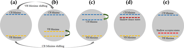
Figure 4. Shift of energy band in band-gap engineering, (a) general CB minima and VB maxima of a photocatalyst, (b) shifting/uplifting of VB maxima, (c) shifting/downshift of CB minima, (d) introduction of donor state below the CB minima, (e) introduction of acceptor state above the VB maxima.
Download figure:
Standard image High-resolution imageThe main approach of engineering the bandgap of a photocatalyst is to broaden solar light absorption spectra from UV to Visible region, which enhances the density of charge generation resulting in boosting photo-reactivity and charge separation. Therefore, for selecting a photocatalyst for an efficient and higher quantum yield application, the principal step is to choose matching bandgap with the activating light source, competence in excitation and generation of e−─h+ pairs, charge separation and environment friendliness [5, 33, 35].
Doping and metal incorporated photocatalyst
One of the embryonic approach to enhance photocatalytic reaction is by doping process, introducing co-catalyst materials/sensitizers, and others. Doping can be grouped into four types: (i) Self-doping, (ii) Metal-doping, (iii) Non-metal doping, and (iv) Co-doping. In association with different types of doping, mid-gap energy states are established between the conduction band minima and valence band maxima (shown in figures 4(d), (e)). In metal ion-doped semiconductor oxides, reduction reaction primarily occurs through electron transfer reaction to the metal ions via single or multiple steps, additionally, interfacial charge transfer and separation. The presence of surface defects suppresses charge carrier recombination, acting as a reaction site [14, 35, 111, 112]. Also in a doped photocatalyst material, dopants act as trappers for the photo-generated e−s and h+s; trappings, and de-trapping of h+s and e−s (shown by a series of reactions in table 4) [113, 114].
Table 4. Role of defects and surface defects in photocatalysis reaction in charge transfer.
| Trapping |


|
| De-trapping |


|
| Surface defects (SD) |


|
Doping of metals or non-metals introduces either new band levels (acceptor or donor levels based on both the type of material and dopant) also known as impurity state levels in between conduction band and valence band or shifting of Fermi level. By co-doping with S and V into Sr2Ta2O7 shifted the valence band maxima upward and conduction band minima downward [115]. Also, doping Cu ions into the ZnO resulted in narrowing the bandgap by shifting valence band downward due to the presence of Cu2+ ions and with the increase in Cu2+ ion concentration, the narrowing of band gap increases due to the difference in electron distribution [116]. However, not all alterations in a photocatalyst yield positive results as the introduction of dopants into a pristine semiconductor may slow down the reaction processes due to an increase in the recombination of e−─h+ pairs in the dopant sites [33, 100]. Yin et al [117] widely studied bandgap and band edge modification using generalized gradient approximation (also validated by hybrid density function method) by substituting/co-doping certain percentage of O and Ti from TiO2. It was found that the concentration of dopants affects bandgap and band edge positions. The binding energy of co-doped material is calculated by [110]:

where:  are total energies with donor and acceptor on Ti and O sites,
  is the total energy of TiO2.
Shifting to multicomponent photocatalysts, designing of multicomponent photocatalysts give heterojunction interfaces between the constituting materials and therefore suitable band edge materials are chosen to build heterostructures. In the case of semiconductor-metal heterostructured photocatalyst, a space charge region called Schottky barrier is formed in the interface. The alignment of Fermi level to attain equilibrium takes place in the interface by flowing e−s from material with higher Fermi level or lower work function to lower Fermi level or higher work function forming an electric field in the contact region [76, 118, 119]. Here, metal with higher work function acts as e− trappers and make itself excessively negatively charged, consequently making the corresponding semiconductor into positively charged in excess. Therefore, these e− trapping phenomena assist in improving exciton separation and inhibit in charge carrier recombination. For example, Ag nanoparticles in AgBr or AgCl, produce surface plasmon resonance induced electric field developed in the metal and semiconductor contact region. This phenomenon enhanced photocatalytic activity in sunlight illumination by transferring e−s from Ag metal to semiconductor AgBr, equilibrating Fermi levels (shown in figure 5) [76].
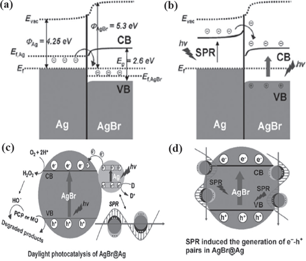
Figure 5. Charge transfer mechanism between energy levels in Ag nanoparticles doped in AgBr (a) energy level before daylight illumination, (b) charge transfer and separation after daylight illumination with surface plasmon resonance phenomenon in Ag nanoparticles, (c) photocatalysis in AgBr@Ag in presence of daylight illumination, and (d) surface plasmon resonance induced charge carriers generations in AgBr@Ag [76] John Wiley & Sons. © 2012 WILEY‐VCH Verlag GmbH & Co. KGaA, Weinheim.
Download figure:
Standard image High-resolution imageOne of the hot emerging photocatalyst material is plasmonic material, where noble metal nanoparticles like Ag, Au, are incorporated with another photocatalyst to form complex hybrid photocatalyst. These plasmonic photocatalysts are known to absorb solar energy and form an internal electric field when illuminated by the light of sufficient energy where charge generation takes place followed by a similar photo-redox mechanism to that of conventional reaction mechanisms. The localized surface plasmon resonance originates when the incident light wavelength is greater than the size of the metal nanoparticle, and free e−s oscillate in the nanoparticle surfaces in phase with the incident electromagnetic field [50, 118, 120]. Here, charge carriers are separated by the developed surface plasmon resonance electric filed, increasing the quantum efficiency and with the direct e− transfer from plasmonic metal to the counter material [77, 118]. In plasmonic photocatalysis cases, two main mechanism take place: plasmon- assisted photocatalysis (by the influence of irradiation: energy transfer and charge transfer) and plasmon-assisted catalysis (by the influence of heating: plasmonic heating). The plasmon-assisted catalysis are due to the photothermal effect caused by the strong local electromagnetic field by the noble metal nanoparticles to the adjacent semiconductor or environment. Thus, the process assisted in generating additional charge carriers, and hence affecting photocatalytic reactions [121, 122]. In the case of bimetallic photocatalyst like Au-Pd nanoparticles, the catalytic activity is attributed by the plasmonic photocatalysis. However, when bimetallic photocatalyst coupled with semiconductor photocatalyst, ex. Au-TiOx-Pd catalyst, both the photothermal as well as plasmonic photocatalysis affect overall catalytic reactions thereby enhancing the process [123].
Heterostructured hybrid photocatalyst
Shifting to multicomponent photocatalyst, suitable band edge materials are integrated forming hybrid heterostructures. The hybrid multicomponent photocatalyst improves light absorption efficiency and optimizes charge separation-recombination process where one material act as a photosensitizer for the other material. This heterojunction is conceivably in between semiconductor-semiconductor, semiconductor-metal, metal-metal, and metal-insulator. Here, semiconductors can be organic or inorganic and depending on their majority charge carriers, it can be n-type or p-type. Hence, heterojunctions are the combination of n and p-type semiconductor, forming n-n, p-p, n-p/p-n heterojunctions [5, 124, 125].
In few cases of heterostructures, semiconductors are assumed to be an insulator when partnered with less bandgap material since absorption of light is limited to UV region of the electromagnetic spectrum and less electric property [5, 56, 126]. In n-p/p-n type heterojunction, one n-type semiconductor is in contact with other p-type semiconductor forming heterojunction interface with space charge region developed by e−s and h+s diffusion in opposite directions, thereby creating a built-in electric potential. This built-in potential uplift charge transfer rate, eliminating recombination and increasing carrier lifetime. The potential drive e−s from higher conduction energy level to lower conduction energy level and h+s will transfer from the lower valence level to higher valence band level. Succinctly, the mechanisms of e−─h+ transfer from one material to another strongly depend upon work function or conduction band and valence band levels, with the type of triggering reaction- oxidation or reduction. In heterostructures, charge transfer encounters less barrier and therefore due to the built-in potential and band matching, more number of e−s and h+s migrate in the opposite directions, thereby amplifying photo-redox reactions. However, to construct an efficient heterojunction, constituting materials should acquire matching bandgap or potential [76, 108, 127].
Xie et al [125] illustrated band alignment and charge separation between n-type SrFe12O19 and p-type Bi2O3 heterojunction; e−s were transferred from n-type to p-type and h+s from p-type to n-type (shown in figure 6). The magnetic field generated inside the magnetic component further cooperated in propelling photogenerated e−s and h+s, thereby complementing each other [125]. The optical band gap of n-n type hetero-structured ZnFe2O4/BiVO4 fall to be in between the bandgap of an individual component and photons are absorbed by less bandgap material (ZnFe2O4), where e−s are transferred to less negative conduction band material (BiVO4) to the counter component [124].
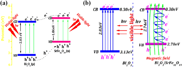
Figure 6. Heterojunction between p-type Bi2O3 and n-type SrFe12O19 (a) charge transfer between the junction and (b) energy level matching and photoinduced electrons flow under visible light irradiation. Reprinted with permission from [125] Copyright (2013) American Chemical Society.
Download figure:
Standard image High-resolution imageBased on the charge excitation-separation and conduction band minima-valence band maxima alignment of the constituting semiconductor materials where the discontinuity or band-offset lies, semiconductor-semiconductor heterostructures are of four types. They are shown in figure 7 with semiconductor A and semiconductor B: (i) Type I (straddling gap), (ii) Type II (staggered gap), (iii) Type II (direct Z-scheme), and (iv) Type III (broken gap). Thus, due to the presence of band-offset, charge carriers experience a potential barrier in the junction and therefore can control the motion and flow of charge carriers. In Type I straddling gap semiconductor heterojunction, the CB and VB of one semiconductor shows more positive and more negative respectively as compared to the counter semiconductor material. Therefore, photoexcited e−s are transferred from the more negative CB to less negative CB and h+s are transferred from more positive VB to less positive VB between the two comprising semiconductors (from semiconductor A to semiconductor B) [128].
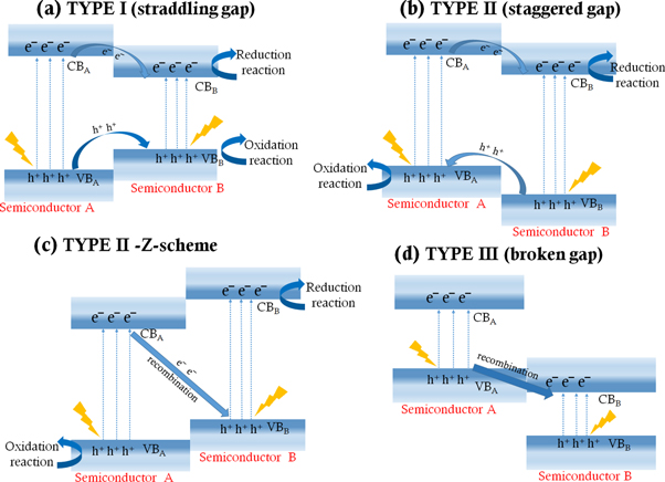
Figure 7. Different types of heterostructures and redox reactions associated with the charge transfer between semiconductor A and semiconductor B, (a) Type I (straddling gap), (b) Type II (staggered gap), (c) type II - direct Z-scheme, and (d) Type III (broken gap).
Download figure:
Standard image High-resolution imageIn contrast to Type I heterojunction where photoexcited h+s and e−s are transferred from one semiconductor to the corresponding semiconductor (example: TiO2/BiVO4 [129]), Type II heterostructures transfer photoexcited h+s and e−s in opposite directions. The charge transfer in Type II heterojunctions may follow two different pathways: conventional and direct Z-scheme, as shown in figures 7(b) and (c). The oxidation and reduction reaction takes place in different semiconductor surfaces for Type II heterostructure while the redox reaction for Type I heterostructure takes place in a single semiconductor surface, therefore charge separation and involvement of charge carriers in a redox reaction are more in Type-II heterostructures. The above-mentioned p-p, n-p/p-n, n-n heterojunctions are introduced and designed under Type II heterojunction category [130]. The photoexcited e−s in the more negative CB transfer either to the less negative CB (conventional charge transfer, example CuWO4/Mn3O4 [131]) or to the VB of the counter material (direct Z-scheme, example g-C3N4/TiO2 heterostructure. And, these e−s recombined with the h+s, thereby, increasing photoexcited e−- h+ separation, generating more e−s and h+s for reductive and oxidative reactions, resulting in the enhancement of photocatalytic efficiency [132].
The type III heterostructures are quite different from the above types as the chances of charge transfer in between the dissimilar semiconductors are rare, therefore losing the significance of engineering heterostructures [130]. The h+s of semiconductor A recombines with the photoexcited e−s of semiconductor B and redox reaction takes place in different semiconductor surfaces [128]. With the development in different catalyst types, the major concern of retrieving and reusability of catalyst was solved by using magnetic-based catalyst materials like ferrites based catalyst for its easy magnetic separation, e.g. n-n heterogeneous structure of ZnFe2O4 and BiVO4 [124]. Apart from multi-component photocatalyst and doping, size variation is further one of the major influencing factors of bandgap manipulation. It is noted that band gap increases and is quantised with the decrease in particle sizes by localization of energy bands and edges [13, 133].
Carbon-based photocatalyst
Another development in the field of hybrid photocatalyst has been a carbon-based heterogeneous catalyst as an approach towards environmental friendliness and availability, despite the well-accepted contribution by pure carbon-based materials. These catalysts are essentially composites of two or more semiconductor compounds co-partnered with carbon nanotubes (multi-walled or single-walled), [134] carbon quantum dots, [135] two-dimensional graphene with quantum dots [74, 75] or graphite composites, [74] and reduced graphene oxides [136].
The carbon-based heterogeneous photocatalysts are organic and known for its potential green catalyst; surface porosity properties of carbon-based materials are an asset in providing trapping active sites and modulates electrical properties of the composite, as carbon-based materials are conductive. Apart from enhancing photocatalytic properties, it acts as an anchoring surface or template for other partnered elements or compounds. [74, 134, 135] B.A deli and F.Taghipour had studied the effect of graphene oxide hybridization on Rh-loaded GaZnON–rGO photocatalyst and found an enhancement in the H2 evolution after graphene oxide hybridisation due to the effective electrochemical interaction between the graphene oxide sheets and composite photocatalyst [89]. Choi et al showed that ZnO coupled with single walled carbon nanotubes (SWCNTs) exhibit higher performance as compared to the ZnO coupled with multi walled carbon nanotubes (MWCNTs) by providing efficient transport of charge carriers and stabilization of free electrons in contrast with the MWCNT due to their metallic property [137]. The presence of heterojunction interface between CNTs and ZnO reduces charge carrier recombination and increases hole extraction by the semiconducting SWCNTs and free electron transport by the metallic SWCNTs thereby improving the performance [137, 138]. The charge carrier generation and transfer in the heterojunction interface of the metal oxide and graphene quantum dot were explored by Sudhagar et al and showed the enhancement of photocurrent in the composite by 70% due to the compatible type II bandgap alignment. Here, the photogenerated charge carriers were separated where photogenerated h+s in graphene quantum dots were transferred to the solution for water oxidation and photogenerated e¯s were collected by the semiconductor oxide (TiO2), thereby enhancing the photocurrents [6]. To understand the photophysical processes, Godin et al had studied the charge trapping-detrapping in graphitic carbon nitride photocatalyst through photoluminescense and time-resolved absorption as deep trapping of charge carriers reduced photocatalytic efficiency. In this context, the presence of deep traps slowed the charged transfer kinetics from the carbon nitride to the neighbouring material, also, due to the deep trappings, large energy loss were took place resulting in decreasing the driving force of charge transfer [139]. Therefore, certain material has to be tuned, designed and optimized to enhance the photogenerated charge carriers generation and transfer, and tune the charge carriers trapping-detrapping for a productive involvement in the photocatalytic reactions.
A possible photogenerated charge transfer mechanism between a semiconductor material and conducting CNT is depicted in figure 8(a). The figure 8(b) shows the illustration of the charge transfer mechanism in a semiconductor photocatalyst molecules that are grown or anchored in a substrate by chemical or physical deposition or lithography techniques for the mineralization of wastewater pollutants via the production of charged particles.
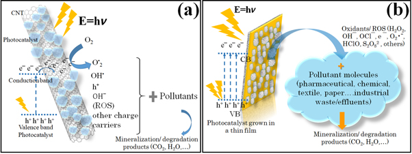
Figure 8. Possible charge transfer phenomenon and pollutant mineralization with the photogenerated charge carriers, ROS and other charged particles by using (a) carbon nanotubes (CNT) functionalized by photocatalyst, and (b) photocatalyst grown in a thin film.
Download figure:
Standard image High-resolution imagepH influence on photocatalysis reaction
One of the simplest and fundamental way to engineer photocatalyst properties like optical, electrical, size, morphology is to adopt variable synthesizing routes and preparation parameters. In conjunction with material properties, factors like pH, concentration and type of pollutants, amount of catalyst loading, and inclusion of charge ion scavengers are also a major factor for revising demineralization or degradation of pollutants with high efficacies (shown in figure 9).

Figure 9. Various factors affecting Photocatalytic reactions.
Download figure:
Standard image High-resolution image
It is prominent that photocatalysis reaction efficiency is the synergy of all these properties and considering single properties confines solely in that singular material and reaction conditions by keeping other characteristics as constants. However, one of the main contributing factors is the pH of the reaction medium as the production of ROS and interaction of catalyst-pollutant are majorly influenced by pH. On that account, by keeping other characteristics constant, the pH of pollutant containing solution affects surface charge properties of the catalyst by its alkaline and acidic nature, either negatively or positively charged and therefore, hinders the interaction between catalyst and pollutant molecules thereby affecting van-der-Waals attraction or electrostatic repulsion. Due to variability in functional groups/types present in catalyst like oxides/sulphides, their responses to a modest change in pH of untreated water (either acidic or basic) fluctuates degradation/demineralization reaction rate. The increase in pH implies the presence of extra OH− ions and less pH means more H+ ions. However, controversy arises as the main charge carriers for photodegradation reaction includes OH‾ ions/radicals and, e−s/h+s, because of the pH variable effect and its charge carrier contribution in different pH range [140]. Thus, for the catalyst that tends to attract OH‾ ions like oxides (TiO2, ZnO etc.), formed aggregates due to excessive OH‾ ions in the solution, and obstruct light penetration to each catalyst molecules. Thus, the formation of aggregates reduces the interaction of light in addition to reducing the amount of pollutant molecules absorption. In some reactions H2SO4, H2O2, NaOH and other pH changing solutions are used to adjust the desired pH level. Semiconductors like ZnO, SnO2, TiO2 prefer for near-neutral pH (pH = 6 or 7) in their suspensions as compared to its acidic (catalyst surface gets protonated) and basic (catalyst surface gets deprotonated) suspensions owing to its surface charges and nanoparticles distribution in the suspension [140].
Analysing apart from a material point of view, the effect of pH can also be seen from molecular interaction, which is the electrostatic interaction between pollutant molecules and reactive oxygen species (attractive/repulsive). Therefore, depending upon the molecular interaction, a certain reaction is either accelerated or decelerated. The pollutants possess different charge when suspended in a medium (cationic/anionic/amphoteric). To conclude all theories, the relation between solution pH and surface charge of catalyst is defined by point zero charges, pHZPC of the catalyst as a deciding factor of the optimum pH of a catalyst for a certain reaction [141–143]. The reaction pH higher than pHZPC delivers negatively charged catalyst surface and lower than pHZPC provide positively charged catalyst surface. At pHZPC, the catalyst is uncharged and electrostatic repulsion is outweighed by van-der Waals attraction and consequently, the size of catalyst increases by agglomeration [144]. Agglomeration of catalyst material also led to decreasing degradation rate due to the aggregate formation inhibiting light penetration by scattering and decline in pollutant-catalyst interaction. Summing up, the photocatalytic activity is a synergistic effect of several inter-dependent parameters and a small modification in any of these parameters showed merits or demerits, yet some controlling factors for photocatalytic activity are pH, [145] catalyst concentration & loading, [146] surface defects, [90] particle size and porosity, [62] surface hydroxyl groups present, [13] photocatalyst calcination [86, 103], irradiation time & intensity [142]. From all the study it is found that the formation and release of H2O2 is the main event that takes place during photochemical degradation via photochemical oxidation of the presence of oxygen/moist atmosphere/aqueous reaction medium.
Conclusion and perspective
The photocatalysis process has been adapted for several environmental applications- water and air pollution treatment but the lab-scale implementations. Photocatalyst materials evolved from using ordinary elemental and transition metal oxides (TiO2/ZnO) to the use of more advanced and beneficial semiconductor oxides by many approaches. Some approaches are to couple ordinary oxides with other elements/compounds as an impurity/doping, modelling hybrid/composite, sensitizers by combining more than two elements/compounds as in core-shell, MOFs or functionalization. In fabricating hybrid photocatalyst, the bandgap is manipulated to match for charge carrier excitation-separation-transfer process. Doping introduces new interband levels between conduction and valence band, and varying shape and size results in shifting valence band upwards or conduction band downwards (depends upon doping-n-type/p-type). The hybrid photocatalyst is designed to exhibit superior efficiency as compared to their constituting counterpart materials by uplifting light absorption capacity and wavelength regimes in the electromagnetic spectrum, charge carrier separations and lifetimes and reduces recombination rates. Depending upon the type of comprising individual photocatalyst material, the hybrid heterostructured interface shows different properties—Schottky barrier, n-n, n-p/p-n, p-p type heterojunctions. These heterojunctions drive the photogenerated charge carriers into opposite directions, hence increasing charge separation and lifetime by reducing recombination. The development of heterostructured photocatalyst assists in shifting the light absorption from UV to visible regimes (sunlight) as a target to utilize sunlight/white light for the photocatalysis process. Photocatalysis reaction is simple yet complicated in determining reaction rate as each step can be altered by changing a single factor. It is a synergistic effect of numerous facets like doping, light absorption capacity/light intensity, type of photocatalyst employed, the concentration of a photocatalyst and pollutant molecules, pH of the reaction medium and others. Therefore, an optimum amount of these depending factors is to be established for a particular photocatalyst and pollutant type. The material properties either physical/chemical/optical/electrical play a significant role in determining photocatalysis reaction rate; porous catalyst interacts to more pollutant molecules and hence more degradation, doping/defect sites act as a trap for charge carriers/recombination centres in some cases. Some mainly affecting photocatalyst properties are surface area, porosity, defects, surface charge, pollutant charge, pH of the reaction medium, size and morphology of the photocatalyst, etc. This review article highlighted the evolution of photocatalyst from a simple catalyst and its development to reach advanced hybrid photocatalyst for the advance oxidation process. The photocatalyst classification based on their composition and a thorough insight of fundamental principles and mechanisms, influence of pH has discussed in detailed. Apart from confining to photocatalysis, exploring to the other upgraded field like photoelectrocatalysis, a combination of electro- and photocatalysis, for the environmental applications, is also an intriguing and provoking topic to explore as a future scope. Apart from the theory point of view, the photocatalysis application field has been studied from a long time and are vastly studied attaining maturation in lab scale investigation. However, the mass or bulk application that lead to commercialization has been pulled down by various factors like light penetration blocking in thick coatings, leaching effect, difficult in photocatalyst recovery etc. Therefore, the future work should be focused into finding solutions of large scale production, commercialization and uses.
Acknowledgments
The authors of this review article would like to acknowledge the financial support given by the Ministry of Human Resource Development, India.
Data availability statement
No new data were created or analysed in this study.
Conflict of interest
There is no conflict of interest between the authors.