

Abstract
Hydrogen absorption and desorption isotherms have been measured for several metal hydride alloys identified as possible candidates in the high-pressure (i.e. >80 MPa) stage of a two-stage hydrogen compressor. The isotherms were obtained using two independent Sieverts volumetric test systems built specifically for measuring hydrogen absorption and desorption parameters from 0.10 to 100 MPa. The results obtained enabled us to identify the alloy Ti0.8Zr0.2Fe1.6V0.4 as the most viable of the candidates investigated for use in the high-pressure stage of a prototype two-stage 80+ MPa compressor, as it produced the highest desorption pressures at moderate temperatures. Issues and challenges in determining reliable isotherms at pressures >50 MPa are also described.
Export citation and abstract BibTeX RIS

Original content from this work may be used under the terms of the Creative Commons Attribution 4.0 license. Any further distribution of this work must maintain attribution to the author(s) and the title of the work, journal citation and DOI.
1. Introduction
Conventional mechanical compressors often contribute over half of the cost of a hydrogen fueling station. They also have reliability issues, and may have insufficient flow rates for a mature fuel cell electrical vehicles market [1]. Fatigue associated with their moving parts, including diaphragm cracking and seal failure that is exacerbated by the repeated starts and stops expected at fueling stations also leads to failure of conventional compressors. Furthermore, the oil lubrication of these compressors is generally unacceptable at fueling stations due the potential for fuel contamination.
Metal hydride (MH) technology offers a very good alternative to both conventional (mechanical) and more recently developed (i.e. electrochemical, ionic liquid pistons, etc) methods of hydrogen compression [2]. The advantages of MH compression include design and operational simplicity, minimal use of moving parts, compactness, expectations for safety and reliability, and the possible utilization of waste industrial heat rather than locally generated or purchased electricity for much, if not all, of the heating required for MH compressor beds. This latter attribute is a major potential benefit of MH compression, as it suggests a dramatic reduction in operating costs. It also offers the attractive scenario of on-site generation, pressurization and delivery of pure pressurized hydrogen (⩾87.5 MPa) for vehicle refueling at electrolysis, wind, or solar generating production facilities in distributed locations that are too remote or widely distributed for cost-effective bulk transport such as conventional hydrogen pipeline or tanker truck supplies.
MH hydrogen compression utilizes the reversible, heat-driven reaction between a hydride-forming metal, alloy or intermetallic compound with hydrogen gas to form a MH phase. This is a promising process for hydrogen energy applications [3, 4]. The original objectives of this work were to investigate a laboratory-scale, two-stage MH hydrogen gas compressor with a feed pressure of ∼5 MPa and demonstrate its ability to deliver high purity hydrogen gas at outlet pressures ⩾87.5 MPa. The scope and status of the full US Department of Energy-sponsored project are described in recent reports by Johnson et al [5, 6]. Previously determined intermetallic compounds and alloy properties [3] were used initially to assess and select two or three appropriate MHs candidates for each of the two stage of this prototype compressor. In this study, the chosen alloys that should be viable for the higher-pressure stage were synthesized and their thermodynamics and hydrogen capacities were characterized with respect to their ability to satisfy the energy requirements and efficiency performance required for hydrogen compression operating at pressures >70 MPa. Efforts at Oak Ridge National Laboratory (ORNL) and Greenway Energy (GWE) included experimental evaluations of the most promising alloys to establish their suitability for use in the higher pressure stage of a prototype compressor fabricated by Sandia National Laboratories (SNL).
2. Background
The feasibility of MH compressors has been known from past demonstrations and limited commercial units since the early 1970s [7]. This method is based on disassociation of diatomic hydrogen molecules into atoms that can dissolve within the host metals or alloys, forming interstitial MH phase(s) [8]. When the hydride is cycled between a lower (TL) and higher temperature (TH), pressure increases as described by Lototskyy et al [3]. This pressure increase is strongly dependent upon the intrinsic thermodynamic parameters for this reaction between the starting and final phases, which often restrict the operating temperature range and stabilities of the hydrides with regards to various degradation processes including disproportionation reactions [3] and contamination by impurities in the hydrogen gas. Because of these issues, MH compressors often use two or more stages employing hydrides with increased operating pressures over a restricted temperature range [3, 4]. This concept is illustrated in figure 1, which was developed and discussed by Yartys et al [4].

Figure 1. A schematic representation for operating a two-stage MH hydrogen compression system, which is based upon the van't Hoff plots derived from pressure–composition–temperature isotherm measurements, when cycling between low (TL) and high temperature (TH). The black lines represent stage 1 (lower black line) and stage 2 (upper black line) hydrogen compression. The dashed red line B–C represents the hydrogen gas flow from the stage 1 low-pressure hydride (HL) to stage 2 high-pressure hydride (HH). The compression cycle is summarized as follows: position A: a low-pressure hydrogen supply (e.g. an electrolyzer or pipeline) is connected to the stage 1 hydride (HL) with a supply pressure Ps. The temperature of the HL bed is maintained at TL during this exothermic hydrogen absorption reaction. A sensible heating process (i.e. step A–B) raises the HL bed temperature to TH, desorbing gas from HL and increasing pressure in the stage 1 vessel. Step B–C: the coupling between stage 1 (dehydrogenation at TH) and stage 2 (hydrogenation at TL) allows hydrogen released from HL at TH to be absorbed by the second MH HH at TL. Step C–D: stage 2 the HH bed undergoes sensible heating, releasing its absorbed gas in order to achieve the delivery pressure of Pd. Position D: dehydrogenation of the stage 2 hydride releases high pressure hydrogen at Pd from the compressor. Finally, both stages are cooled to temperature TL (i.e. returning to A and C) with the hydrogen connection between hydrides closed. Adapted from Yartys et al [4] (2016). With permission of Springer.
Download figure:
Standard image High-resolution imageIt is important to point out that figure 1 represents an idealized hydrogen absorption-compression-desorption cycle. Very few MHs possess constant absorption and desorption pressures across the entire plateau regions as well as the absence of absorption/desorption hysteresis, which were assumed in this representation [4]. These complications have been discussed more thoroughly by Lototskyy et al [3].
Using hydrogen absorption and desorption isotherms measured for the intermetallic alloys La0.85Ce0.15Ni5 (stage 1) and C14-Laves phase Ti0.65Zr0.35(Mn,Cr,Fe,Ni)2 (stage 2), Yartys et al [4] described how a two-stage operation makes it possible to achieve hydrogen compression from PL = 10 atm to PH = 200 atm (i.e. a compression ratio ∼20) over the temperature range from 20 °C to 130 °C. This behavior is summarized in figure 2, but it should be pointed out that quantity of hydrogen actually compressed is less than predicted using ideal isotherms for these hydrides.

Figure 2. Hydrogen absorption (TL = 20 °C, a) and desorption (TH = 130 °C, d) isotherms with La0.85Ce0.15Ni5 (1) and C14-Laves phase Ti0.65Zr0.35(Mn,Cr,Fe,Ni)2. (2) The two-stage hydrogen compression from PL = 10 bar to PH = 200 bar involves the following processes: AB: hydrogen absorption in the stage 1 MH at PL and TL; BC: hydrogen desorption from the stage 1 MH on heating to T = TH, generating an intermediate pressure, PM; CD: hydrogen absorption in the stage 2 MH from stage 1 at PM and TL; DEF: hydrogen desorption from the stage 2 MH at TH and PH. The circled area is the minimum amount of the transferred hydrogen (ΔCH) during the two-stage hydrogen compression process ABCDEF. Curves 1a and 1d are the low- and high-temperature isotherms for the stage 1 MH, respectively, and likewise, curves 2a and 2d are the low- and high-temperature isotherms for the stage 2 MH. The TL isotherms are shown in blue and the TH isotherms are shown in red. Adapted from Yartys et al [4] (2016). With permission of Springer.
Download figure:
Standard image High-resolution imageThe compression ratio envisioned for the high-pressure prototype MH compressor at SNL was ⩽17.5 (i.e. from ⩾5 to ∼87.5 MPa). This is smaller than that described in by Yartys et al [4]. Thus, this ratio should be obtainable provided MH alloys with appropriate properties are identified. Various MH compressors have been developed recently that operate with discharge pressures from 10 MPa to over 40 MPa [9, 10]. However, the very few Pd >50 MPa hydride compressors previously demonstrated were custom laboratory versions with limited size or pumping capacities that were primarily suitable for specialized applications and operating conditions [2, 3].
A number of properties of the candidate hydrides that also significantly impact the performance of the hydride compressors must be considered beyond their isotherms and the specific design and construction of their container vessels. For instance, only hydrides with sufficiently rapid hydrogen absorption and desorption kinetics, resistance to disproportionation reactions during extended thermal cycling, minimal hysteresis ratios, minimal sensitivity to contaminants in the hydrogen gas, and a resistance to particle size breakdown following cycling are suitable. The roles and impacts of these factors as well as other issues are discussed thoroughly in several recent publications [3, 4, 9–11].
3. Assessments, identification and characterization of candidate alloys for high-pressure hydride beds
The number of potential metal-hydrogen systems suitable for hydrogen storage and energy conversion is vast. Extremely diverse materials react with hydrogen gas under conditions suitable for many types of applications [9–12]. However, as discussed in depth by Lototskyy et al [3] and Yartys et al [4] only a relatively small subset of interstitial-type MHs have the reversibility behavior and reaction kinetic properties appropriate for hydrogen compression applications. Furthermore, other than a very few elemental hydrides (e.g. VHx ) nearly all of the practical hydrides for hydride compressors are crystalline intermetallic compounds based upon: (a) body-centered-cubic (BCC) vanadium (V); (b) hexagonal AB5 alloys formed by substituting for La and/or Ni in LaNi5; (c) AB2 phases with either the hexagonal C14 Laves structure or the cubic C15 Laves structures; or (d) various alloys of cubic TiFe.
A number of candidate alloys for both low pressure (LP) and high pressure (HP) MHs were surveyed during the initial phase of this study. A subset of these was identified for further assessment based on past experience, literature review, and design requirements for a two-stage compressor with a delivery pressure >80 MPa at desorption temperature <180 °C.
The following alloys were considered:
HP candidates (phase and crystal structure type)
- (a)TiCr1.6Mn0.2 (AB2 C14)
- (b)Zr0.8Ti0.2FeNi0.8V0.2 (AB2 C15)
- (c)TiCr1.8 (AB2 C15)
- (d)(Ti0.97Zr0.03)1.1Cr1.6Mn0.4 (AB2)
- (e)TiCrMn0.7Fe0.2V0.1 (AB2)
- (f)Ti1.1CrMn (AB2)
LP candidates (phase type)
- (a)MmNi4.7Al0.3 (AB5)
- (b)Ti0.9Zr0.1Mn1.4Cr0.35V0.2Fe0.05 (AB2 C14)
- (c)TiMn1.66Vf0.34 (AB2 C14/C15 mixed Hydralloy C1)
- (d)Ti0.25Zr0.75Fe1.0Ni0.8V0.2 (AB2 C-15)
- (e)TiCr1.6Mn0.2 (AB2 C14)
From this list alloys that could be obtained commercially were selected for possible testing of their behavior with hydrogen. Ames Laboratory (Ames Lab) at the Iowa State University (USA) and Japan Metals & Chemicals Co., Ltd (JMC) in Japan were able to provide one or more of the alloys of interest, and SNL had ∼100 kg of GfE Hydralloy C5 (Ti0.955Zr0.045Mn1.52V0.43Fe0.12Al0.03), which had been identified as a potential low-pressure candidate, from a previous project. JMC provided alloys they had in-stock, whereas Ames Lab custom synthesized nominal 50 g alloy batches via arc-melting, then sealed these in quartz tubes for heat treatment at 900 °C for 240 h in argon, followed by a water quench. The four alloy samples fabricated by Ames Laboratory for this purpose were all titanium-based AB2-type MHs: (a) Ti0.95Zr0.05Cr1.2Mn0.75V0.05, (b) Ti0.8Zr0.2Fe1.6V0.4, (c) Ti1.0Cr1.0Mn0.7Fe0.2V0.1, and (d) Ti0.6Zr0.4Fe1.0Ni0.6V0.4 These will be referred to as Ames #1, #2, #3, and #4 (respectively). Since limited published isotherm data were available for these alloys [13–16], insufficient information was available to select a high-pressure hydride for the stage-2 beds of the prototype compressor. The candidate alloys were, therefore, characterized using PCT (pressure, composition, temperature) volumetric Sieverts systems at ORNL and GWE to obtain the desired absorption and desorption isotherms.
3.1. Descriptions of the Seiverts systems for measuring the high pressure isotherms
Isotherm measurements were conducted collaboratively, but independently, at ORNL and at GWE. The volumetric measurements performed at ORNL were accomplished using a custom-designed and fabricated Sieverts system configured to test hydrogen absorption and desorption in hydride metal powders at pressures from 1 to 100 MPa and temperatures from 20 °C to 175 °C. The vacuum station consisted of an oil-less scroll pump and a turbomolecular pump. An external high-pressure gas booster provided high-pressure hydrogen for absorption measurements, and each component as well as the assembled system were routinely tested for leaks using a helium leak detector.
The ORNL Sieverts system employed a reactor vessel (High Pressure Equipment Corporation microreactor MS-16) with an internal volume which would be sufficient for testing up to 85 g of hydride alloy with hydrogen pressures ⩾80 MPa at desorption temperatures >150 °C and maximum hydrogen content mass loadings of approximately 1.5 wt%. An internal 316 stainless steel filter tube and three filters containing 10 µm porous discs were placed inline in the tubing connecting the sample reactor to the rest of tbe system to prevent migration of small hydride alloy particles into the system manifold. Alloy temperatures during testing were measured used an Inconel-sheathed type-K thermocouple fed through the end of the vessel opposite the isolation valve and immersed in the sample powder. The disassembled ORNL reactor vessel is shown in figure 3.

Figure 3. The disassembled components of the ORNL high-pressure Sieverts reactor, including the isolation valve and internal porous 316 l stainless steel filter tube. The dimensions are indicated by the measuring tape with scale marks in inches. The coupling for the internal sheathed thermocouple is on the right side of the reactor with valve connecting on left side.
Download figure:
Standard image High-resolution imageThe alloys characterized at ORNL were loaded in a glove box under a nitrogen or argon atmosphere. After loading, the reactor vessel was sealed in the glove box before its removal and connection to the Sieverts system. The vessel was then evacuated using the turbopump vacuum system for several hours. The integrated system was then leak-checked using high-pressure (>80 MPa) helium and an Agilent model DSPD03 leak detector with a sniffer probe for testing vessels pressurized with helium. Following calibration of the internal volume of the loaded reactor and connecting lines volumes using helium, a procedure was initiated to activate the sample prior to measurement of the absorption and desorption isotherms. The initiation of sample activation was indicated by sample temperature increases of ∼10 °C after introduction of a small quantity of hydrogen. After activation began, pressure was increased to ∼15 MPa. The sample was presumed to be fully activated when its temperature returned to room temperature and the equilibrium pressure remained constant for >1 h. Absorption isotherms were measured at equilibrium pressures up to about 35 MPa and desorption isotherms were measured at temperatures up to 150 °C–175 °C. Desorption was performed as soon as possible after the absorption measurement was complete. Experiments were conducted with this system on Ti0.95Zr0.05Cr1.20Mn0.75V0.05 (Ames #1) and three separation preparations of Ti0.8Zr0.2Fe1.6V0.4 [14] (denoted as Ames #2A, #2B and #2C).
MH alloys undergo volume dilatation and contraction during hydrogen sorption and desorption. The accompanying changes in sample volume in our measurements were accounted for in the isotherm calculations by correcting the void volume for sample expansion and contraction in the reactor. The volume expansion for the Ti0.8Zr0.2Fe1.6V0.4 alloy is ΔV/V = 0.206 at a hydrogen content of 1.8 wt%, which occurs at an equilibrium pressure of about 148 MPa [14]. Our corrections treated the sample dilatation and contraction as a linear function of the equilibrium pressure. During the ORNL measurements of the three preparations of Ames alloy #2, the decrease in void volume at an equilibrium pressure of 50 MPa ranged from 0.4 to 0.9 cm3. Similar, but somewhat smaller changes occurred for the GWE measurements as the sample vessel contained lesser amounts of the alloys for the isotherm determinations.
The values for hydrogen pressure in the isotherm calculations were obtained using the Abel–Nobel equation of state [17], which accurately describes the real gas behavior of hydrogen at pressures less than 200 MPa and temperatures between 223 K and 423 K.
The high-pressure volumetric measurements performed at GWE used a custom, high-pressure Sieverts system described in detail elsewhere [16]. The GWE equipment, which had recently been used to assess [16] the hydrogen absorption and desorption isotherms of Ti1.1CrMn MH material at pressures up to about 90 MPa, performed similar measurements on the alloys Ti0.8Zr0.2Fe1.6V0.4 (Ames #2) and Ti1.0Cr1.0 Mn0.7Fe0.2V0.1 (Ames #3) and Ti0.6Zr0.4Fe1.0Ni0.6V0.4 (Ames #4).
3.2. X-ray diffraction characterization of selected alloy candidates
Although the crystal structures and lattice parameters for several candidate alloys had been reported previously [13–15], it was decided to examine two of the alloys produced by Ames Laboratory. Dr Michael Cheshire (ORNL) kindly performed these powder x-ray diffraction (XRD) measurements. The phase identifications and lattice parameters the Ames #2 and #3 alloys are summarized in table 1.
Table 1. Phase identifications and lattice parameters for the alloys characterized by powder XRD [e] at ORNL.
| Composition | Ames Lab ID | Condition | Major phase | a (nm) a | c (nm) a | Volume (nm3) a | Other phases |
|---|---|---|---|---|---|---|---|
| Ti0.8Zr0.2Fe1.6V0.4 | #2B | As-cast | C14 b | 0.48895(3) | 0.79643(4) | 0.16490(1) | None |
| Ti0.8Zr0.2Fe1.6V0.4 | #2B | Annealed | C14 | 0.48874(3) | 0.79654(4) | 0.16477(1) | FCC c |
| TiCrMn0.7Fe0.2V0.1 | #3 | Annealed | C14 | 0.48649(1) | 0.79833(1) | 0.163629(6) | FCC d |
Notes: XRD measured using a Malvern Panalytical Empyrean diffractometer with copper Kα x-rays. a The uncertainties in the last digits are indicated by values within the parentheses. b Laves phase C14 is hexagonal with the space group P63/mmc crystal structure. c A small, undetermined amount of a face centered cubic (FCC) phase was observed in this sample. d An FCC phase (a = 5.7009(3)Å) with a content of ∼16% by volume was observed in this sample.
4. Isotherm characterizations of the high-pressure hydride candidates
The room temperature absorption isotherm obtained at ORNL for Ames #1 (Ti0.95Zr0.05Cr1.20Mn0.75V0.05) is shown in figure 4. Following these absorption measurements, several of the pneumatically operated valves in the Sieverts system began leaking due to the downstream migration of hydride powder from the sample volume into the manifold, which prevent measurement of the subsequent desorption isotherm. The results obtained are, nonetheless, consistent with literature data [13], and indicate that Ames #1 can be easily charged to a capacity >1.5 wt.% in the low-pressure stage of the compressor at a reasonable temperatures. Desorption pressures for the alloy at up to 180 °C were in excess of 87.5 MPa when starting at this high initial hydrogen content; however, the desorption pressures are too small at lower contents to meet the requirements necessary to serve as the second stage in a >80 MPa compressor.

Figure 4. Room temperature (i.e. 297 K) hydrogen absorption isotherm for Ti0.95Zr0.05Cr1.2Mn0.75V0.05 (Ames #1) alloy.
Download figure:
Standard image High-resolution imageThe Ames #2 alloy (Ti0.8Zr0.2Fe1.6V0.4) was examined at both ORNL and GWE. It was found to have the highest desorption pressure capability of all the high-pressure candidate alloys evaluated during this project. Isotherms were measured at room temperature (i.e. ∼293–299 K) on three preparations of this alloy labelled #2A, #2B, and #2C, after the previously mentioned leaking pneumatic valves had been repaired by the manufacturer. Hydrogen absorption isotherms for these three Ames #2 samples are compared in figure 5 and are seen to be very similar with each other except for small variations being primarily attributed to the temperature differences during the independent measurements at ORNL and GWE. Figure 5 shows that room temperature absorption by the Ames alloys require a hydrogen pressure >30 MPa in order to reach hydride capacities greater than 1.2 wt%, which is a lower threshold than ∼1.5 wt% capacity indicated from the 20 °C absorption results previously reported by Zotov et al [14] for a nominally identical alloy composition. There are two factors that could account for this difference as well as the greater absorption pressures also observed in this work across most of the plateau region for the Ames alloys: (a) The crystalline volume shown in table 1 for the annealed Ames #2B alloy is 0.1648 nm3, which is smaller than the volume 0.1651 nm3 reported by Zotov for their unannealed alloy leading to lower capacities and higher pressures as suggested from the 'geometric model' for intermetallic hydrides [18]. (b) The XRD results for the annealed Ames #2B alloy in table 1 also indicate the presence of a secondary FCC phase, which is likely to be the C15 structure, generating very similar changes as recently observed [16] in hydriding behavior for an annealed alloy of Ti1.1CrMn containing a mixture of the C14 and C15 phases.

Figure 5. Room temperature hydrogen absorption isotherms measured at ORNL and GWE for three Ames Laboratory preparations of the alloy Ti0.8Zr0.2Fe1.6V0.4 (Ames #2) compared to the isotherm obtained at 20 °C by Zotov et al [14] on an alloy with the same nominal composition.
Download figure:
Standard image High-resolution imageDesorption of hydrogen from reacted alloy Ames #2B (figure 6) at ∼90 °C, starting from an initial composition of 1.27 wt %. generated a pressure greater than 90 MPa. However, while the Ames alloy #2 is a viable candidate for the high-pressure stage of a compressor, the highly sloping plateau region of its isotherms prevents it from achieving the desired compression ratio via room temperature absorption (i.e. the stage-1 hydride must provide a greater initial pressure to sufficiently charge the stage-2 hydride bed). Hence, the initial candidate hydrides identified for the stage-1 bed of the SNL prototype compressor would be inadequate, requiring that another alloy had to be selected [5, 6].

Figure 6. The pressure increase observed at ORNL for Ti0.8Zr0.2Fe1.6V0.4 (Ames #2A alloy) upon heating. The initial hydrogen composition of the alloy at room temperature was 1.27 wt%.
Download figure:
Standard image High-resolution imageThe hydrogen absorption and desorption isotherms obtained on Ames #2A and #2B alloy samples at three temperatures are presented in figure 7. Due to the very high equilibrium pressures generated at elevated temperatures, measurements were limited to hydrogen contents less than ∼1.0 wt.% in order not to exceed the 100 MPa upper limits of the pressure transducers of the ORNL and GWE Sieverts systems. Nevertheless, these results clearly indicate that Ti0.8Zr0.2Fe1.6V0.4 hydride exhibit rather modest hysteresis behavior and is a viable candidate for the upper stage of a prototype 80+ MPa compressor operating with a maximum temperature <160 °C during desorption.
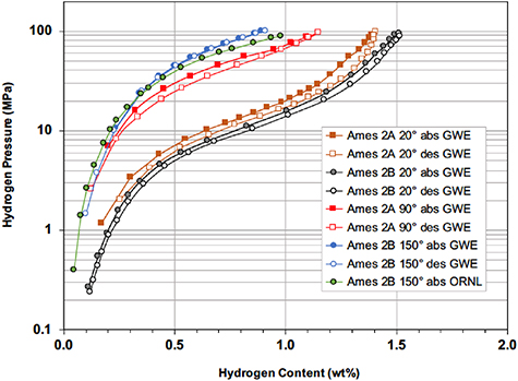
Figure 7. Comparison of GWE and ORNL hydrogen absorption and desorption isotherms for two preparations of Ti0.8Zr0.2Fe1.6V0.4, Ames Alloy #2A and #2B.
Download figure:
Standard image High-resolution imageThe hydrogen absorption and desorption isotherms of the alloy Ti1.0Cr1.0Mn0.7Fe0.2V0.1 (Ames #3) measured at GWE are shown in figure 8. This hydride has a very good storage capacity along with relatively broad and flat plateaus exhibiting only modest hysteresis. However, the desorption pressures are not sufficiently high for this hydride to serve as the stage-2 bed for an 80+ MPa compressor without heating to temperatures above ∼200 °C. On the other hand, this alloy does appear to be an attractive candidate for use in MH compressors with lower pressure requirements or for other reversible hydrogen storage applications.
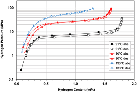
Figure 8. Hydrogen absorption and desorption isotherms measured at GWE on Ti1.0Cr1.0Mn0.7Fe0.2V0.1 (Ames #3).
Download figure:
Standard image High-resolution imageThe final candidate examined in this study, Ti0.6Zr0.4Fe1.0Ni0.6V0.4 (Ames #4), was characterized using the GWE system. Results obtained at three temperatures are shown in figure 9. Although this hydride exhibits relatively little hysteresis between its absorption and desorption pressures, the total storage capacity is not especially large and the isotherms have substantial slopes in the plateau regions. These properties exclude its usage in a stage-2 compressor bed. However, Ames #4 was selected as a viable stage-1 candidate for the SNL prototype compressor because it can supply hydrogen fill pressures greater than ∼20 MPa during desorption at reasonable temperatures.

Figure 9. Hydrogen absorption and desorption sotherms measured at GWE for Ti0.6Zr0.4Fe1.0Ni0.6V0.4 (Ames #4).
Download figure:
Standard image High-resolution image5. Description of experimental issues and challenges for high-pressure measurements
During the hydrogen absorption and desorption isotherm measurements made during this work, the ORNL Sieverts apparatus experienced recurring hydrogen leaks, both internally thorough the manual and pneumatic valves and externally at various fittings. These were mostly observed at higher pressures (i.e. >50 MPa) even though helium leak detector examinations indicated the apparatus was completely leak-free upon assembly at ambient temperature. An example is shown in figure 10 for Ames alloy #2A. This alloy should achieve hydrogen desorption pressures >100+ MPa when the hydride that had been charged to full stoichiometries (i.e. >1.2 wt.%) then heated above ∼100 °C. As can be seen, however, the maximum pressures remained at only ∼50 MPa as the bed temperature increased above 80 °C. This contrasts with the behavior exhibited in figure 6 for a separate lot of the same alloy. Further examination of this test confirmed that an internal leak arose across one of the previously repaired pneumatic valves and was responsible for this problem. It was necessary to replace this valve with a manually actuated one to eliminate the leak. Such behavior suggests that all the valves in a system designed for this purpose should have in-line porous filters with 1 µm or smaller media grade installed on the sample side to prevent migration of alloy or hydride powder caused by the very large pressure drops that develop during desorption. With regards to addressing such powder contamination issues, Gray and Webb [11] have recommended the utilitzation of much finer filtration frits with pore dimensions of circa 50 nm or even smaller during very high pressure operations to prevent migration. Based upon our troublesome experiences, this is very sound advice.

Figure 10. Pressure increase for Ames Lab #2A upon heating. Pressure did not increase above ∼50 MPa when the hydride was heated above ∼90 °C in this experiment due to an internal valve leak.
Download figure:
Standard image High-resolution image
6. Summary and conclusions
Following a comprehensive review of the literature on potential reversible hydrides, where nearly all alloys had either the AB5 or AB2 crystal structures, several viable candidates for both the low- and high-pressure stages of 80+ MPa compressors were identified. Four alloy candidates for possible use in the high-pressure stage were selected and appropriate samples were procured for volumetric characterization of their hydrogen absorption and desorption behaviour at pressures up to 100 MPa.
After the isotherm measurements were performed at ORNL and GWE, the alloy Ti0.8Zr0.2Fe1.6V0.4 (Ames #2) was chosen for the high-pressure stage 2 of the SNL prototype compressor [5, 6]. It produced the highest desorption pressures at moderate temperatures. Based upon its isotherm measurements, this latter hydride can operate from PL of <40 MPa at a TL of ∼20 °C and produce PH > 87.5 MPa at TH of 150 °C.
While the preminary results obtained on Ti0.95Zr0.05Cr1.20Mn0.75V0.05 (Ames #1) and Ti1.0Cr1.0 Mn0.7Fe0.2V0.1 (Ames #3) indicated both should function reasonably well for the second stage of a 70 MPa compressor, the temperatures needed to generate the desired pressures (>80 MPa) from these alloys are probably too high to be practical choices.
The AB2 alloy Ti1.0Cr1.0Mn0.7Fe0.2V0.1 (Ames #4) was selected for stage-1 of the SNL prototype compressor to operate from 20 °C to 150 °C covering the modified pressure range from PL ∼15 MPa for absorption to PH > 45 MPa during desorption. This hydride was chosen because the minimum absorption pressure for this stage needed to be increased from ∼5 to >15 MPa in order to generate sufficient hydrogen pressure during its desorption to allow the ambient temperature absorption by the stage-2 alloy Ti0.8Zr0.2Fe1.6V0.4 (Ames #2) to achieve a sufficiently high hydrogen content. Finally, it is recommended that an accelerated temperature-pressure cycling assessment of the degradation behavior should be performed on the Ti0.8Zr0.2Fe1.6V0.4 hydride to established whether performance lifetime targets for a 80+ MPa hydrogen compressor would be met during extended operation necessary for proposed refueling applications.
Acknowledgments
This research was supported by the United States Department of Energy (DOE) Office of Energy Efficiency and Renewable Energy, Fuel Cell Technology Office. ORNL is operated by UT-Battelle LLC for DOE under contract number DE-AC05-00OR22725. The authors wish to acknowledge the valuable contributions and support from Professor Craig Jensen of Hawaii Hydrogen Carriers. The authors appreciate the analyses, discussions, and other contributions by Terry Johnson and Anne Mallow from Sandia National Laboratories to these studies as part of the DOE high-pressure compressor project. The authors also wish to thank Matt Besser (ISU Ames Laboratory) for discussions and preparation of the alloys and Dr Michael Cheshire (formerly of ORNL) for his work on the XRD analyses.
The views and opinions of the authors expressed herein do not necessarily state or reflect those of the United States Government or any agency thereof. Neither the United States Government nor any agency thereof, nor any of their employees, makes any warranty, expressed or implied, or assumes any legal liability or responsibility for the accuracy, completeness, or usefulness of any information, apparatus, product, or process disclosed, or represents that its use would not infringe privately owned rights.
Data availability statement
The data that support the findings of this study are available upon reasonable request from the authors.