
Creep Damage Repair of a Nickel-Based Single Crystal Superalloy Based on Heat Treatment

1
School of Mechanics, Civil Engineering and Architecture, Northwestern Polytechnical University, Xi’an 710072, China
2
School of Science, Xi’an Shiyou University, Xi’an 710065, China
3
School of Aerospace Engineering and Applied Mechanics, Tongji University, Shanghai 200092, China
*
Author to whom correspondence should be addressed.
Metals 2021, 11(4), 623; https://doi.org/10.3390/met11040623
Submission received: 26 February 2021
/
Revised: 8 April 2021
/
Accepted: 9 April 2021
/
Published: 13 April 2021
Abstract
:Taking nickel-based single crystal superalloy DD6 as the research object, different degrees of creep damage were prefabricated by creep interruption tests, and then the creep damage was repaired by the restoration heat treatment system of solid solution heat treatment and two-stage aging heat treatment. The results show that with the creep time increasing, the alloy underwent microstructure evolution including γ′ phase coarsening, N-type rafting and de-rafting. After the restoration heat treatment, the coarse rafted γ′ phase of creep damaged specimens dissolved, precipitated, grew up, and became cubic again. Except for the specimens with creep interruption of 100 h, the γ′ phase can basically achieve the same arrangement as the γ′ phase of the original sample. The comparison of the secondary creep test shows that the steady-state creep stage of the test piece after the restoration heat treatment is relatively increased, and the total creep life can reach the same level as the primary creep life. The high temperature creep properties of the tested alloy are basically recovered, and the restoration heat treatment effect is good.
1. Introduction
Aero-engines are used in harsh environments such as high temperature, high pressure, high speed, and gas corrosion. Turbine blades are the key rotating hot end components, and their life and reliability directly affect the performance and safety of the aircraft. Nickel-based single crystal superalloys are widely used in aero-engine turbine rotor blades due to their excellent high-temperature mechanical properties and oxidation and corrosion resistance [1,2]. However, under the combined action of high temperature, high speed, and complex stress, turbine blades often inevitably produce damage, such as creep damage, fatigue damage, and corrosion damage, resulting in the decline of blade materials and mechanical properties [3,4,5,6,7]. When the blade damage accumulates to a critical value or reaches the design life, it is necessary to replace the new blade to ensure the safe operation of the engine. However, the replacement of blades often brings high manufacturing costs. Therefore, the life extension technology and performance recovery of aero-engine turbine blades have great economic and practical significance [8].
At present, there has been more research on the repair methods of turbine blades, mainly including laser cladding, welding, additive manufacturing, machining, heat treatment, etc. [9,10,11,12,13,14,15,16,17,18,19,20,21]. However, unlike methods such as laser cladding and additive manufacturing, recovery heat treatment has advantages in engineering applications such as low cost and low technical difficulty. In addition, during the creep process of nickel-based single crystal alloys, alloy elements will diffuse significantly under the combined action of temperature and stress, and the γ′ phase will grow up along a certain direction and appear directional coarsening, that is, rafting [22,23]. It is impossible to recover these microstructure changes and damages only by laser cladding and other methods, and recovery heat treatment has an irreplaceable effect. For recovery heat treatment methods, there have been some related studies, such as Baldan [9] studied the recovery heat treatment of cast alloy IN-100. He pointed out that when the volume fraction of γ′ is close to 50% and it is cubic, the energy of the γ/γ′ interface increases and the movement of dislocations is more difficult, thereby increasing the alloy′s endurance life. Koul et al. [10] studied the microstructure changes before and after service of the aero-engine stage I turbine blades and the repair effect of the coating heat treatment on the service blades. Due to the incomplete dissolution of primary γ′ in the heat treatment process, and the existence of primary γ′ depletion zone, coarse γ′, and secondary MC carbides near the grain boundary, the creep cavity produced in service cannot be eliminated by heat treatment alone, so the microstructure of 713C alloy can only be partially restored by heat treatment. P Wangyao [13] et al. used hot isostatic pressing (HIP) and different heat treatment conditions to re-precipitate the γ′ of the blade material Inconel 738 alloy, which has been used for a long time, to achieve a more uniform structure than the original alloy. M Sekihara [14] et al. repaired the creep damage caused by the bending load through the reheating process and pointed out that creep damage in Ni-based superalloys can be repaired effectively using the re-heat process before cumulative creep strain reaches a critical value that is restrained by the initiation of harmful precipitation or creep cracks. The above research shows that the creep damage of nickel-based superalloys can be restored by heat treatment, so that the cubic intermetallic compound strengthening phase γ′ can be re-densified and orderly precipitated, thereby restoring the high-temperature mechanical properties of the material. Different materials require different heat treatment repair processes, and there is not much research work on nickel-based single crystal superalloys in this area. Therefore, the nickel-based single crystal superalloy DD6 was selected as the research object, and the damage was prefabricated through creep interruption tests at different times, and then the creep interruption damage was repaired through the recovery heat treatment system of solution and two-stage aging heat treatment. Finally, through the secondary creep experiment of the two test pieces that have not undergone the recovery heat treatment and the recovery heat treatment, the repair effect of the recovery heat treatment system is verified, and the mechanical explanation of the related phenomenon is made.
2. Test Materials and Methods
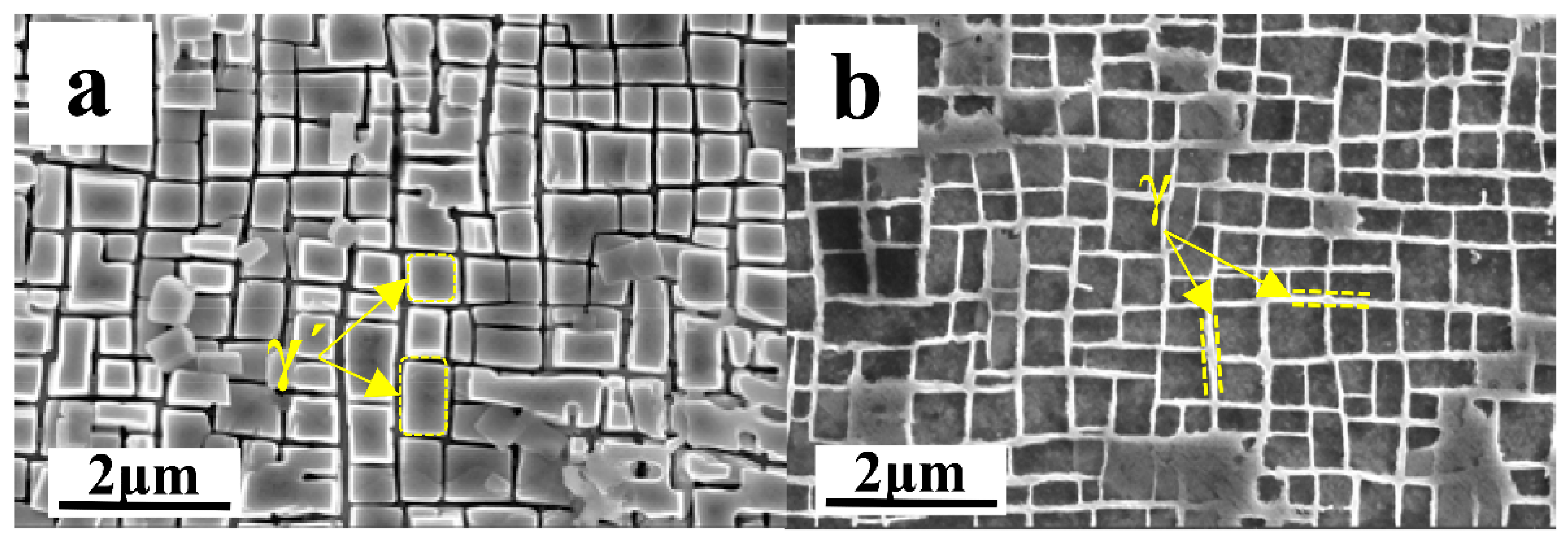
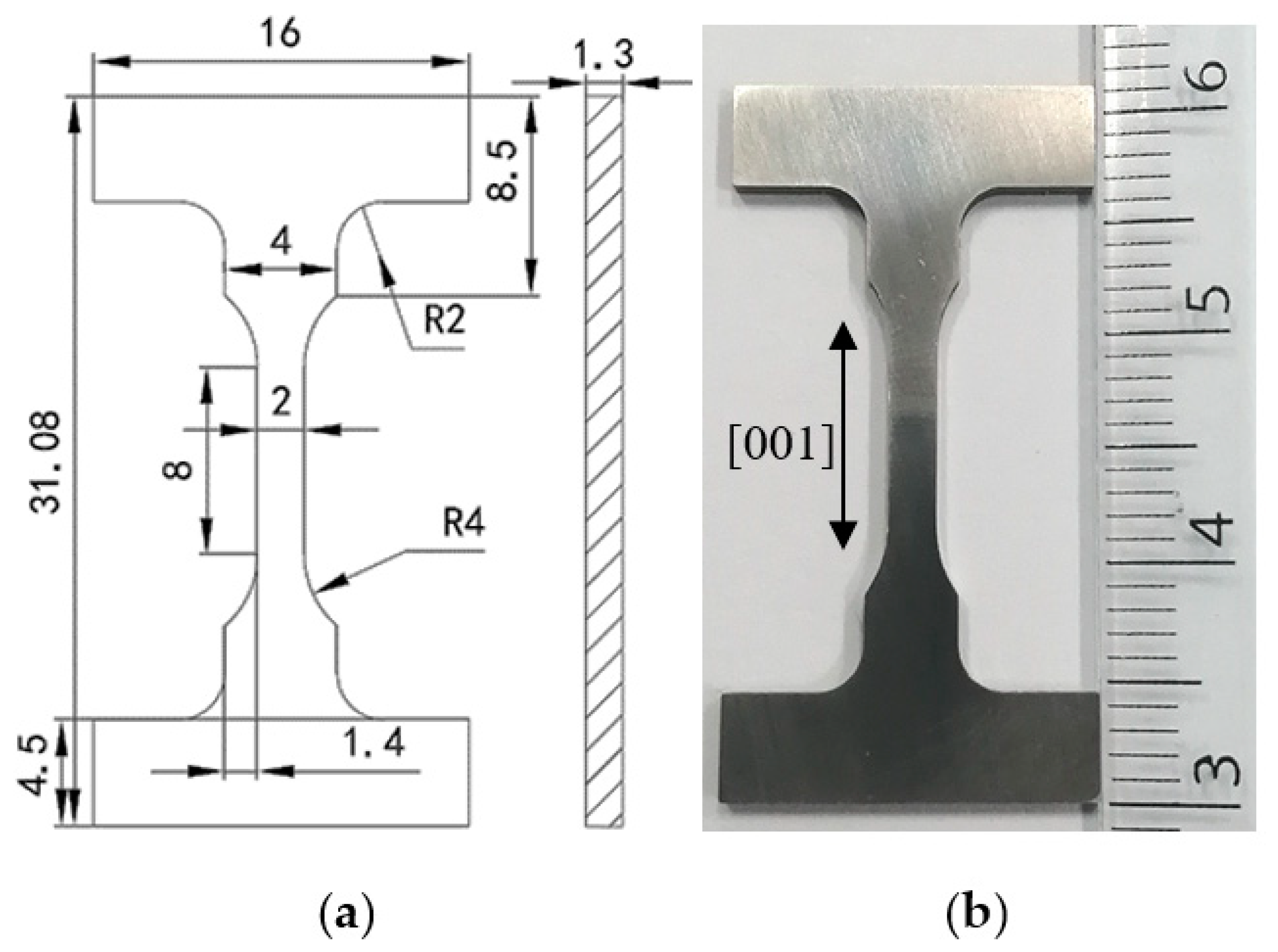
The material used in this study is the second-generation nickel-based single crystal superalloy DD6 for aviation turbine blades and is provided by Beijing Institute of aeronautical materials, and its nominal element content is shown in Table 1. The material is prepared by melting the master alloy in a vacuum induction melting furnace and then casting the as-cast single crystal test bar with (001) orientation in a high gradient directional solidification vacuum furnace. The crystal orientation of the test bar is determined by Lauie′s method, and the deviation between the (001) crystal orientation of the bar and the stress principal axis is kept within 10 degrees. After the standard heat treatment system, the test alloy is a standard two-phase alloy composed of γ phase and γ′ phase. The two phases maintain a coherent relationship. The microstructure is shown in Figure 1. The average size of γ′ phase is about 0.3–0.5 μm, and the volume fraction is about 68%. The γ phase appears as an interlaced grid, as shown in Figure 1b. The size and physical picture of the I-shaped test piece are shown in Figure 2. The length direction of the gauge length of the test piece is the (001) orientation of the test alloy. The processing method will affect the mechanical properties of the alloy to a certain extent by affecting the surface roughness and residual stress of the sample [24,25]. Therefore, in order to avoid these factors, the I-shaped test piece in this study is processed by wire cutting, and the sample surface is polished to the same roughness with 1200 # SiC sandpaper.
In order to simulate the γ′ coarsening, rafting, and other microstructure damage caused by the turbine blades in different periods of service, the high temperature and low stress creep interruption tests with different duration were designed. First, test the creep performance of the test piece under the condition of 1050 °C/170 MPa, and obtain the strain–time curve after creep rupture. According to the strain–time curve, choose different creep interruption time (20 h, 40 h, 70 h, 100 h), and then conduct the creep interruption test under the same test conditions to obtain different degrees of precast creep damage. In order to ensure the reliability of the experimental results, all high-temperature creep tests in this study were completed on the same CSS-2905 high-temperature durable electronic testing machine, and the tests under each condition were tested multiple times to reduce the test error. During the experiment, three S-type thermocouples were used to measure the experimental temperature in the upper, middle, and lower parts of the sample, and ensure that the experimental temperature difference was within ±5 °C. After reaching the creep interruption test time, all the test pieces were removed from the tensile load, the heating was stopped, and they were taken out after being naturally cooled to room temperature. Subsequently, the test pieces with different degrees of creep damage were restoration heat treated in a vacuum high temperature tube furnace. The restoration heat treatment refers to the standard heat treatment system of the test alloy: 1315 °C × 4 h/AC + 1120 °C × 4 h/AC + 870 °C × 32 h/AC (air cooling). The temperature control accuracy of the vacuum high temperature tube furnace is ±5 °C. Argon gas protection is used when the test piece is air-cooled to avoid the influence of high temperature oxidation. After the creep interruption test and the restoration heat treatment, a cube measuring 2 mm × 1.5 mm × 3 mm is cut from the gauge length of the test piece to analyze the microstructure of the sample. The samples are ground, polished, chemically corroded, and ultrasonically cleaned by metallographic analysis method. The composition of the chemical etching solution was: 1% nitric acid HNO3: 2% hydrofluoric acid HF: 3% glycerol C3H8O3 (volume ratio). Zeiss FSEM field emission scanning electron microscope (SEM) was used to observe the creep damage and the microstructure of the alloy at different restoration heat treatment stages. Image-J software was used to statistically analyze the size of the γ′ phase, the width of the γ phase channel, and their morphology and distribution. Finally, the secondary high-temperature creep test under the same conditions of 1050 °C/170 MPa is performed on the test pieces without restoration heat treatment and after restoration heat treatment, so as to verify the effect of the restoration heat treatment.
3. Results and Discussion
3.1. High Temperature Creep Test Results
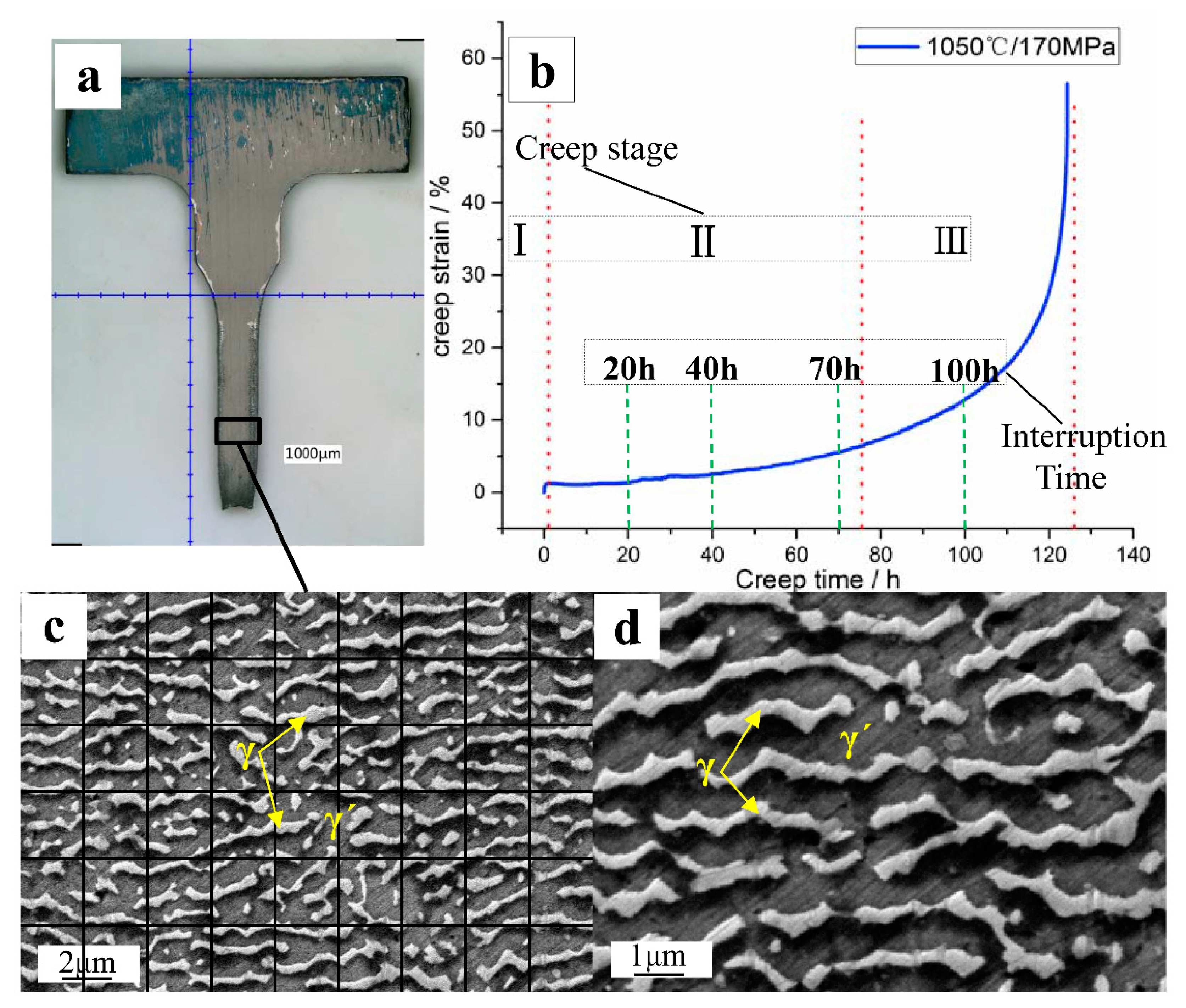
The uniaxial tensile creep properties of the (001)-oriented DD6 alloy test pieces were tested under the conditions of 1050 °C/170 MPa. The test piece after creep rupture and the creep strain–time curve are shown in Figure 3a,b respectively. The creep curve shows that the test alloy has three obvious creep stages. The deceleration creep stage is very short. The alloy has a large creep strain rate at the moment of loading, and then the creep rate decreases rapidly. After about 3 h, the alloy entered the second stage of creep. The steady-state creep stage is longer. There is little change in the alloy creep strain rate at this stage. After 70 h, it enters the third stage of creep. The strain rate increases rapidly in the accelerated creep stage until the alloy creep ruptures, and the creep life is about 124 h. The alloy microstructure after creep rupture is shown in Figure 3c,d. It can be seen that it is significantly different from the original microstructure of the test alloy in Figure 1, and N-type rafting has occurred. The coherence relationship between phase γ and phase γ′ becomes insignificant. The phase γ parallel to the loading direction disappears, and γ′ is connected in the direction perpendicular to the loading direction. According to the creep strain curve, different creep time periods are selected for creep interruption tests. The duration of the deceleration creep phase at the initial stage of creep is too short to be considered. The initial, intermediate, final, and accelerated creep stages of the steady-state creep stage were selected for creep interruption tests, and the corresponding creep times were 20 h, 40 h, 70 h, and 100 h, respectively. The creep strain and creep strain rate corresponding to these four creep stages are shown in Table 2.
3.2. Microstructure after Different Creep Interruption Test Time
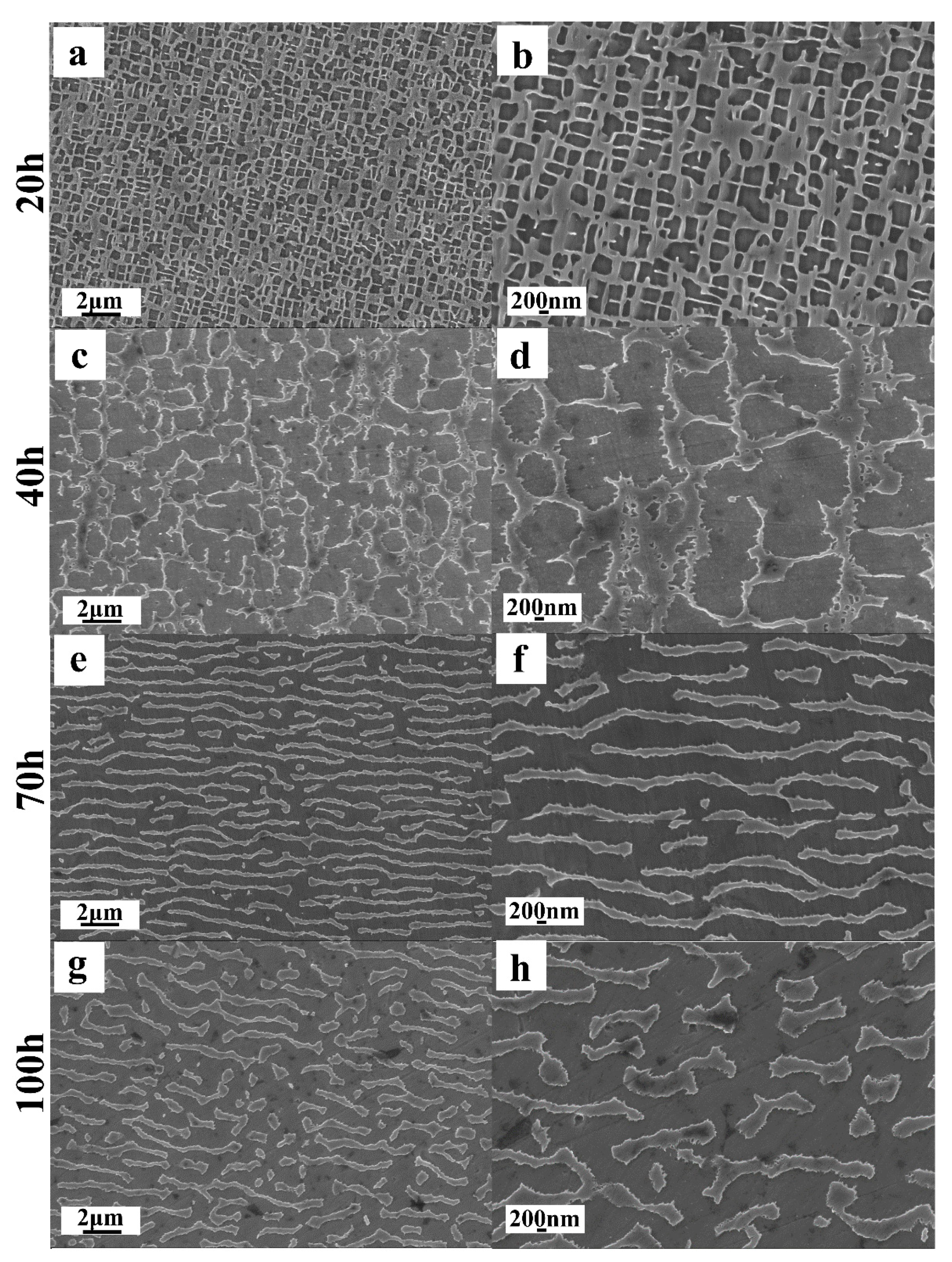
The creep interruption test was performed at different times. Then the gauge length section of the test piece was cut and the microstructure morphology was observed under the scanning electron microscope after metallographic sample preparation. The result is shown in Figure 4. In the process of high temperature creep, the rafting and de-rafting phenomenon of the alloy occurs with the increase of time. The load direction in the experiment is all along the (001) orientation. In this study, the rafted structure is perpendicular to the loading direction, so “⊥” and “//” denote parallel and perpendicular to the loading direction respectively. It is observed that the rafting structure of the alloy is perpendicular to the direction of tensile stress, showing “N” type rafting, which is consistent with the negative value of the lattice mismatch of the test alloy. After 20 h creep interruption test, the microstructure of the test piece is shown in Figure 4a,b. Part of the γ′ phase still maintains a relatively complete cubic structure, while part of the γ′ phase has been slightly deformed and lost the original cubic structure. The overall arrangement of the γ′ phase is no longer regular, but it is still separated from each other and evenly distributed in the γ phase without coarsening. The phase channel perpendicular to the tensile stress loading direction and the phase channel parallel to the tensile stress loading direction still maintain the same width. After 40 h creep interruption test, the microstructure of the test piece is shown in Figure 4c,d. The γ′ phase has begun to coarsen, and its size has increased significantly. The arrangement and distribution have become chaotic, and the cubic γ′ phase is completely invisible. The phase channel perpendicular to the tensile stress loading direction becomes wider, and the phase channel parallel to the tensile stress loading direction becomes narrower. Some γ′ phases have even been connected together, and the rafting phenomenon appears in its embryonic form. After 70 h creep interruption test, the microstructure of the test piece is shown in Figure 4e,f. The γ′ phase has completely lost the original neatly distributed cubic structure and has grown coarsely along the direction perpendicular to the tensile stress loading direction. A strip structure is formed. With the directional growth of the γ′ phase, the phase channels parallel to the tensile stress loading direction basically disappear. The roughened γ′ phases are fused and connected together, and the width of the phase channel perpendicular to the tensile stress loading direction becomes larger. The microstructure of the entire alloy forms a “labyrinth” raft structure. After the 100 h creep interruption test, the microscopic morphology of the test piece is shown in Figure 4g,h. Compared with the alloy microstructure in the 70 h creep interruption test, the γ′ phase is not only oriented along the direction perpendicular to the tensile stress loading direction but also parallel to the tensile stress loading direction. The γ′ phase has changed from an orderly strip structure to a disorderly structure. The γ phase is divided into short strips and the phenomenon of “de-rafting” appears.
The width of the γ-phase channel perpendicular to the direction of stress loading and the width of the γ-phase channel parallel to the direction of stress loading were measured by Image J software, and the average width of the γ-phase channel was calculated. The γ phase and γ′ phase have different contrasts. The γ′ phase area percentage of the white contrast is measured. The area percentage of γ′ phase is converted to the volume fraction of γ′ phase by Formulas (1) and (2),
where is the volume fraction of the γ′ phase, and is the area percentage of the γ′ phase. Through measurement and calculation, the γ phase channel width and γ′ phase volume fraction of the alloy at different creep interruption times are shown in Table 3.
The γ′ phase volume fraction is the most significant parameter affecting its creep performance. As is shown in Table 3. As the creep time increases, the width of the γ phase channel along the direction perpendicular to the stress loading gradually increases, and the γ′ phase volume fraction gradually decreases. When the alloy has a higher volume fraction of γ′ phase, it will show better creep resistance during the creep process. The creep lasting life is longer. In the first stage of creep and the second stage of creep, the γ′ phase volume fraction of the test piece is higher. The creep rate of the test piece is low. The creep strain gradually increases slightly. The alloy creep process is relatively stable. In the third stage, the volume fraction of the γ′ phase of the test piece continuously dropped significantly. The creep rate then increases rapidly. The creep strain increases sharply until creep rupture.
Creep interruption tests at different times showed different rafting degrees of γ′ phase. In order to analyze the effect of γ′ phase rafting on the creep properties of the test alloy, the parameter Ω is selected to indicate the perfection of γ′ phase rafting. Its definition is shown in Formula (3).
In the formula, PL represents the number of interruptions and crossings of the γ′ phase rafting structure per unit length in the specified direction (i.e., the number of times the γ′ phase and the γ phase interface appear in the micrograph), and “⊥” and “//” represent respectively vertical and parallel to the rafting direction. In this study, the rafted structure is perpendicular to the loading direction, so “⊥” and “//” denote parallel and perpendicular to the loading direction respectively. The value of Ω ranges from 0 to 1. When Ω is 0, it means that the γ′ phase has not been rafted. The vertical and parallel directions are equivalent directions, and the γ′ phase is a uniformly distributed cubic shape. When Ω is 1, it means that the γ′ phase is completely rafted, and the γ′ phase is directionally coarsened into a complete layered structure, with neither interruption nor crossing. The closer the value of Ω is to 1, the more perfect the rafting degree of γ′ phase is. The microstructure of the creep interrupted by different creep time is selected, and the pictures are divided into several parts along the vertical and parallel to the rafting direction. The number of interruptions and crossings of the γ′ phase rafting organization is counted, and the value of Ω is calculated. The calculation results are shown in Table 4.
During the high temperature creep process, the directional coarsening of the γ′ phase has a great relationship with the surface energy and coherent stress caused by the mismatch of the γ phase and the γ′ phase [26]. In the first stage of creep, dislocations slip in the γ phase channel, and the γ phase appears plastic deformation. In the second stage of creep, the number of dislocations continues to increase. The γ′ phase prevents dislocation slippage. The creep rate is basically stable, and the cubic γ′ phase is passivated, showing an irregular spherical structure. Under the action of high temperature thermal activation, dislocations accumulate at the two-phase interface to form an interface dislocation network. The γ′ phase appears as a directional coarsening connection, thus forming a sheet-like raft structure. In the third stage of creep, a large number of dislocations accumulate and stress concentration occurs in the alloy. When the stress reaches the critical value, the dislocation starts to cut the γ′ phase, the γ′ phase resistance decreases, and the phenomenon of “de-rafting” appears. The creep rate becomes larger, and the amount of creep strain continues to increase. Microcracks appeared in the test piece and propagated to rupture [27,28]. The rafting degree of the alloy γ′ phase during the creep process is shown in Table 4. With the increase of creep time, the rafting degree of γ′ phase increases first, and then gradually de-rafts.
3.3. Microstructure after Restoration Heat Treatment
The microstructure of the test piece with different creep times interrupted after solution heat treatment is shown in Figure 5. The γ′ phase of the alloy dissolves at 1315 °C for 4 h, and the γ′ phase is fully dissolved in the γ phase to form a single-phase solid solution. After air cooling to room temperature, the γ′ phase precipitates. Due to the short cooling time, the amount of γ′ phase precipitated is more and the size is smaller. The morphology is passivated cubic structure. The four corners of some γ′ phases extend outward and are connected with other γ′ phases, showing a state of initial growth. The arrangement is disorderly and has not formed a certain way of arrangement. After solution heat treatment, the cross section of γ′ phase is basically round. The diameter of a circle with the same area is defined as the equivalent size of the γ′ phase. The equivalent sizes of the γ′ phase in Figure 4b,d,f,h are about 66 nm, 77 nm, 74 nm, and 76 nm. Since there is no obvious phase channel after solution heat treatment, its width is not counted. In Section 3.2, after the creep interruption test of the test piece for different times, the alloy γ′ phase has been rafted to different degrees, which leads to the decrease of creep performance. After solid solution treatment, the rafted structure formed by the γ′ phase is re-dissolved and merges with the γ phase into a uniform single-phase solid solution. After cooling down to room temperature, a large amount of γ′ phase re-nucleated and distributed uniformly. In addition, some black areas can be seen in Figure 4g with a magnification of five thousand times. Through energy spectrum analysis, there is a small amount of O element in this region. During the creep acceleration stage, creep cavities are formed in the alloy. Oxygen enters the alloy through cavities and oxidizes with the alloy elements, forming part of Ni oxide.
The microstructure after the first aging heat treatment is shown in Figure 6. When the alloy was kept at 1120 °C for 4 h, fine secondary precipitates were precipitated continuously. The nucleated γ′ phase can be fully grown by fusing into the nucleated γ′ phase. When the alloy was kept at 1120 °C for 4 h, fine secondary precipitates were continuously precipitated and incorporated into the nucleated γ′ phase, which made the nucleated γ′ phase grow up fully and the equivalent size increased continuously, forming a uniform cubic structure with regular arrangement and obvious phase channels. After the first aging heat treatment, the equivalent sizes of γ′ phase corresponding to creep interruption time of 20 h, 40 h, 70 h, and 100 h are about 401 nm, 455 nm, 447 nm, and 413 nm. The average widths of phase channels are about 134 nm, 150 nm, 154 nm, and 142 nm. Compared with the γ′ phase after solution treatment, the equivalent size of γ′ phase increases obviously and the number of γ′ phase decreases correspondingly after first aging heat treatment, and the arrangement of γ′ phase is close and orderly, showing a cross channel. It can be seen from Figure 6a,c,e that after the first aging heat treatment, the γ′ phases of the pieces with creep interruption time of 20 h, 40 h, and 70 h are uniformly arranged, and the phase channel width in different directions is basically the same. It can be seen from Figure 6g that the γ′ phase of the specimen with creep interruption time of 100 h does not form cubic structure completely after first aging heat treatment, and the phase channel width in each direction is also different. In Figure 6b,d,f,h, many fine secondary precipitates are dispersed in the phase channel. Through element migration, the tiny secondary precipitates are continuously integrated into the γ′ phase and promote the growth of the γ′ phase.
The microstructure after the second aging heat treatment is shown in Figure 7. After holding at 870 °C for 32 h, the alloying elements diffused directionally in the long-term holding process, the fine secondary precipitates in the phase channel were all mixed into the larger γ′ phase, the γ′ phase grew further, its equivalent size further increased, and the cubic structure with neat arrangement was formed. The cube corner was clear, the cubic degree was significantly improved, the arrangement was more compact, and the width of the phase channel became smaller. The equivalent diameters of γ′ phase corresponding to the four creep interruption times are about 484 nm, 459 nm, 477 nm, and 532 nm, and the average widths of phase channels are about 66 nm, 71 nm, 61 nm, and 83 nm. Compared with the γ′ phase after the first aging treatment, the equivalent size of γ′ phase after the second aging treatment increases correspondingly. The arrangement of γ′ phase is more compact and orderly, and the width of the cross channel is greatly reduced. It can be seen from Figure 7a,c,e that after second aging treatment, the γ′ phase of test pieces with creep interruption time of 20 h, 40 h and 70 h can basically reach the arrangement state of the original sample, and the phase channel width in different directions is the same and narrow. It can be seen from Figure 7g that after second aging treatment, the γ′ phase of the test pieces with creep interruption time of 100 h also basically presents cubic structure, and the width ratio of phase channels in different directions also decreases correspondingly, so it is difficult to see the wide phase channels formed by rafting. From Figure 7b,d,f,h, it is difficult to observe tiny secondary precipitates in the phase channel, because the secondary precipitates have been completely integrated into the γ′ phase through the directional migration of elements.
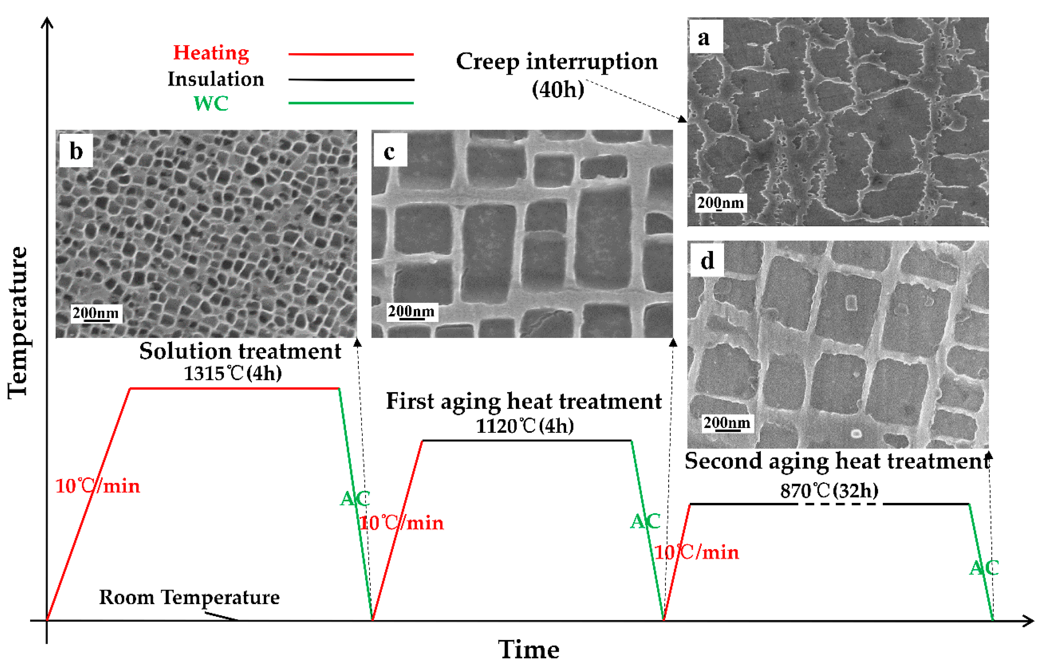
The schematic diagram of the whole heat treatment repair process and the corresponding microstructure of the test piece with creep interruption time of 40 h at each stage of recovery heat treatment are shown in Figure 8. It can be seen that the γ′ phase coarsens obviously after creep for 40 h. After solution heat treatment, the γ′ phase dissolves again and precipitates compactly and orderly. After one-step aging treatment, the size of γ′ phase precipitated in the solution phase increases obviously and becomes cubic. After the second aging treatment, the γ′ phase is further cubic and the overall size is more uniform.
3.4. Secondary High Temperature Creep Performance before and after Restoration Heat Treatment
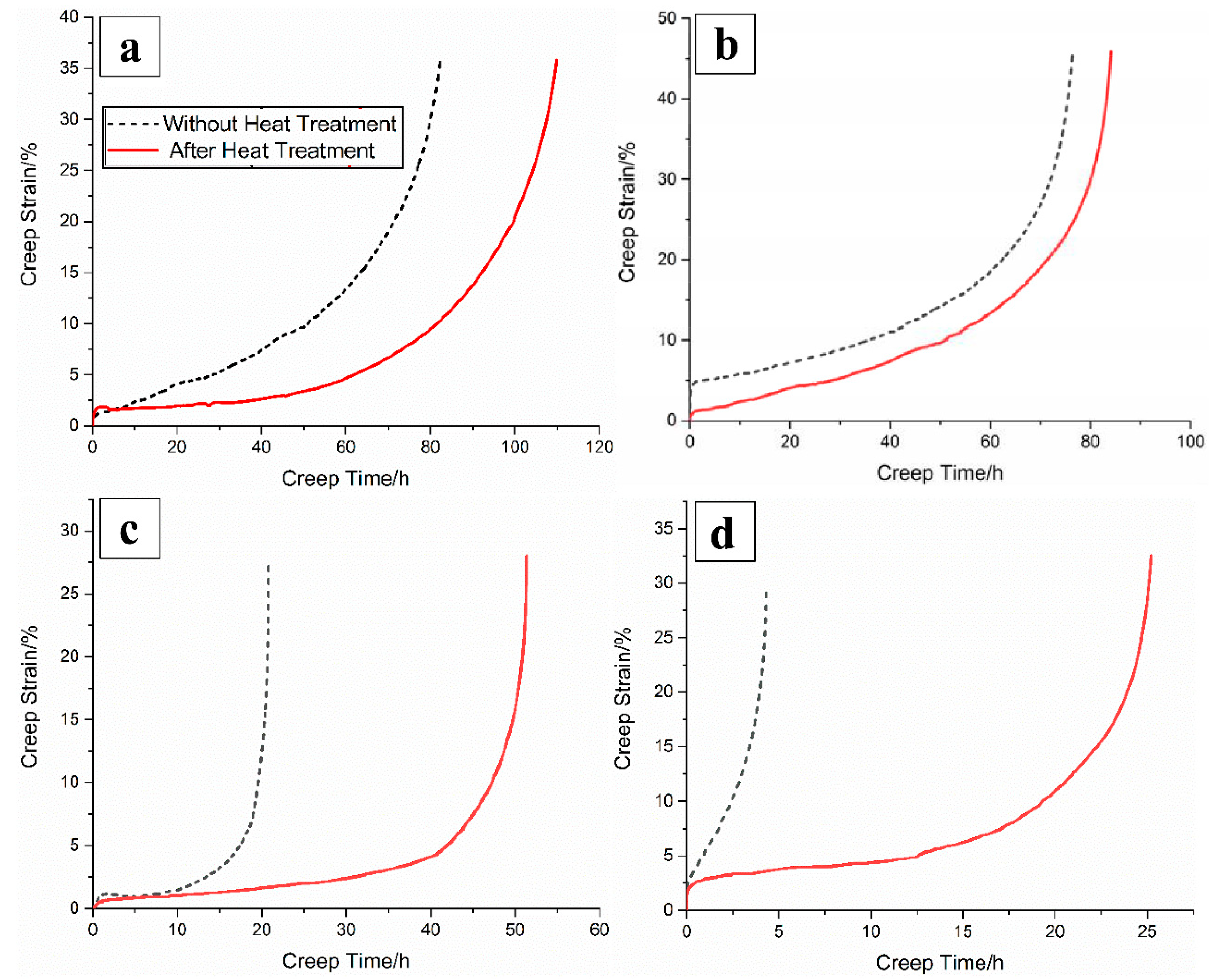
The specimens with creep interruption times of 20 h, 40 h, 70 h, and 100 h were divided into two groups. In one group, the second creep test under 1050 °C/170 MPa was directly carried out on the creep testing machine without restoration heat treatment until the test piece ruptured. In the other group, after restoration heat treatment, the second creep test under 1050 °C/170 MPa was carried out until the test piece ruptured. The test data of the two groups of test pieces are recorded respectively. The creep life is shown in Table 5. The creep curve of the test pieces after the secondary creep test is shown in Figure 9.
It can be seen from Table 5 that the creep life of the test piece with four kinds of creep interruption time is only 82 h, 76 h, 21 h, and 4 h respectively when the secondary creep test is carried out without restoration heat treatment. Compared with continuous creep to fracture, the total creep life after secondary creep tests is decreased, and the creep property of the test piece is decreased to a certain extent. However, after restoration heat treatment, the secondary creep life of the test piece reaches 109 h, 83 h, 51 h, and 25 h respectively. The cumulative creep life of the test piece basically remains the same as that of the original test piece, and the creep property of the test piece still keeps the same level as that of the original test alloy. Compared with the creep life of the test piece without restoration heat treatment, the creep life of the test piece after restoration heat treatment is extended correspondingly, and the repair effect is achieved.
As can be seen from Figure 9, the creep rate of the test piece without restoration heat treatment is larger and the steady-state creep phase is shorter, while the creep rate of test piece after restoration heat treatment is smaller, the steady-state creep stage is obvious, and the creep life is longer. It can be seen from Figure 9a,b that the trend of the secondary creep curve of the test pieces interrupted by 20 h and 40 h creep without restoration heat treatment is basically consistent with that repaired by restoration heat treatment, this is mainly because the specimens under this condition are in the early and middle stage of steady-state creep in the first creep test, the rafting degree of the alloy microstructure is low, and the recovery heat treatment can better repair the microstructure damage.From Figure 9c, it can be seen that the test piece with a creep interruption time of 70 h quickly enters the creep acceleration phase when the secondary creep test is performed without restoration heat treatment, while the test piece restored by restoration heat treatment exhibits a longer creep steady state phase when the secondary creep test is performed. From Figure 9d, it can be seen that the test piece with creep interruption time of 100 h without restoration heat treatment does not experience an obvious creep steady-state state when the second creep test is conducted; while the test piece after restoration heat treatment will first experience a period of creep steady- stage phase and then enter the creep acceleration stage.
3.5. The Effect of Restoration Heat Treatment on the Microstructure of the Material
From the creep interruption test in Section 3.2, it can be seen that the alloy γ′ phase starts from the uniformly distributed cubic block to directional coarsening, rafting, and then to de-rafting. The evolution of the microstructure leads to a gradual decline in alloy properties. Through the restoration heat treatment, the microstructure of the alloy can be repaired, and the γ′ phase appears again in uniformly distributed cubes. It can be seen from Table 6 that after the solution heat treatment, the rafted γ′ phase re-dissolves and resolves small particles with an equivalent size of 70 nm. After the first aging heat treatment, the granular γ′ phase is fully grown to cubes with an equivalent size of about 440 nm, and the cubes are evenly arranged, showing phase channels with an average width of about 140 nm. After the secondary aging heat treatment, the fine secondary precipitation phase merges into the γ′ phase. The γ′ phase grows further and the cubic degree continues to increase. The equivalent size has grown to about 500 nm, and the arrangement is more compact. The average width of the phase channel is reduced to about 70 nm, which is equivalent to the original microstructure of the alloy.
In the phase of solid solution heat treatment, the roughened and rafted γ′ phases are completely dissolved in the γ′ phase after holding at the solution temperature for a period of time, forming a uniform single-phase solid solution. During cooling to room temperature, the new γ′ phase nucleates and precipitates from the γ phase. The nucleation of the γ′ phase needs a certain degree of supercooling, which is shown in Formula (4),
where T0 is the critical temperature and Tn is the actual transition temperature. The relationship between undercooling and driving force is shown in Formula (5),
where L is the exothermic constant of phase transition. A certain degree of undercooling provides the driving force for the phase deformation nucleus, and the nucleation process of γ′ phase appears. The change of free energy of the alloy nucleation system is shown in Formula (6),
where r is the radius of nucleation of γ′ phase, ΔGv is the driving force of phase transition, that is, the difference of free energy per unit volume between liquid and solid γ′ phase. Gε is the elastic strain energy caused by nucleation. σ is the specific interface energy, that is, the increased energy per unit area. According to Formulas (5) and (6), the critical radius of γ′ phase nucleation is shown in Formula (7). The critical free energy of alloy nucleation system is shown in Formula (8).
According to Formulas (7) and (8), the greater the degree of subcooling, the greater the free energy of nucleation of the γ′ phase and the easier the alloy nucleation. The degree of supercooling is a necessary condition for the nucleation of the γ′ phase. The diffusion of atoms to the critical nucleus can form a stable nucleus. The nucleation rate is the number of nucleation per unit time and unit volume of a single-phase solid solution. The nucleation rate is shown in Formula (9),
where f0 is a constant related to atomic diffusion. N0 is the number of atoms per unit volume. k is the Boltzmann constant. T is the test temperature. Q is the diffusion activation energy. With the decrease of test temperature, the activation energy of diffusion will increase, while the critical nucleation energy will decrease. They restrict each other, and the nucleation rate will reach a maximum at a certain temperature. Therefore, in this study, the air-cooling method is selected to ensure that the nucleation rate is large enough and the γ′ phase can be precipitated rapidly and compactly.
During the first and second aging heat treatment, the γ′ phase has reprecipitated and nucleated. The atoms in the phase diffuse continuously, transfer to the precipitated γ′ phase, and the γ′ phase grows up with the atoms. The diffusion velocity at the phase interface of γ′ phase is shown in Formula (10),
where A is the constant, Dv is the diffusion coefficient and ΔT is the degree of supercooling. Undercooling provides driving force for the growth of γ′ phase, which can be replaced by supersaturation Ω0. The diffusion velocity at the phase interface of γ′ phase can be expressed by Formula (11).
According to the formula, the growth of γ′ phase is related to element diffusion rate and element supersaturation. Compared with the nucleation process, the growth of the γ′ phase is relatively slow, the elements continue to diffuse from the matrix phase to the γ′ phase, and the phase interface of the γ′ phase continues to extend outward and grow. At the same time, under the combined action of free energy and interface energy, the γ′ phase gradually transforms from spherical to cubic [29,30,31].
3.6. Effect of Restoration Heat Treatment on High Temperature Creep Properties of Test Alloys
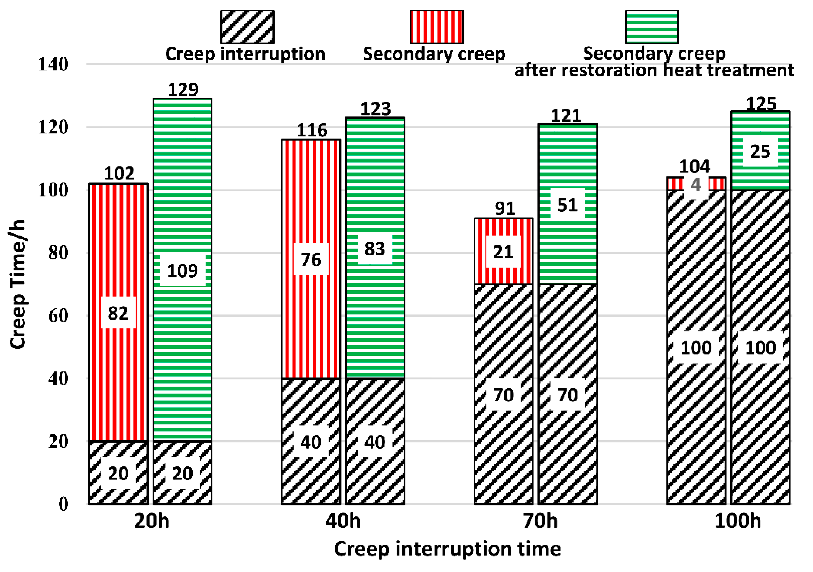
The creep life of the test piece after two creep tests is shown in Figure 10. Combined with the secondary creep curve in Figure 9, it can be seen that the creep rate of the test piece after the creep interruption test is increased, and the total creep life is about 100 h, which is less than the life of the original test piece from one creep to fracture for more than 120 h. In previous studies [32], it was speculated that this phenomenon may be caused by the inhomogeneity of local crystal orientation caused by the accumulation of high-density dislocations. After the creep interruption test, the creep stage of the test piece increases relatively, and the total creep life is more than 120 h, which is about 20% higher than that of the test piece without overheating treatment, and can basically reach the same level as the first creep life. The creep life of the alloy was interrupted for 70 h. in the later stage of the second creep stage, the difference of creep life before and after heat treatment was the largest, and the repair effect was the best. In the solution stage of recovery heat treatment, the deteriorated γ′ phase is completely dissolved in the phase, and the strengthening elements are continuously diffused, re oriented, and migrated to the γ′ phase. The concentration and order of strengthening elements are increasing. The hardness of γ′ phase increases. The critical stress which hinders the dislocation movement increases continuously to achieve the effect of solution strengthening. Ni-based single crystal alloy consists of γ-phase and γ′-phase. The properties of γ/γ′-phase alloys are closely related to the volume fraction of γ′-phase. The creep properties of the alloy can be affected by changing the volume fraction of γ′ phase. During the recovery heat treatment aging stage, the nucleated γ′ phase precipitates continuously and grows up. As the size and volume fraction of γ′ phase increase, the phase channel width decreases. It is very difficult for dislocations to slip between the tightly arranged γ′ phases, and they can only pass through the γ′ phase by bypassing and climbing. The movement resistance of dislocation increases. The creep rate decreases. The steady-state creep stage increases and reaches the strengthening effect of the second precipitate phase. The creep properties of the alloy were improved [27,28].
4. Conclusions
Taking nickel-based single crystal superalloy DD6 as the research object, different degrees of creep damage were prefabricated by creep interruption tests (20 h, 40 h, 70 h, 100 h) at 1050 °C and 170 MPa, and then the creep damage was repaired by solution heat treatment plus two-stage aging heat treatment. The second creep test was carried out to verify the effect of restoration heat treatment. The main conclusions are as follows:
- (1)
- The microstructure after the creep interruption test at four different times (20 h, 40 h, 70 h, 100 h) reflects the evolution process of the microstructure of the experimental alloy γ′ phase directional coarsening-N-type rafting–de-rafting. Solution and two-stage aging recovery heat treatment system is: (1315 °C × 4 h/AC + 1120 °C × 4 h/AC + 1120 °C × 4 h/AC + 870 °C × 32 h/AC, AC means air-cooling). In the solution heat treatment, the disordered γ′ phase of the creep interruption test piece was re-dissolved and precipitated in an orderly and dense manner. The two aging heat treatments increased the size of the re-precipitated γ′ phase, cubed it, and made the phase size uniform. After the recovery heat treatment, except for the 100 h test condition where the creep is interrupted, the remaining γ′ phase can basically reach the arrangement state of the original sample γ′ phase.
- (2)
- After the creep is interrupted and then the second creep test is carried out, the total creep life is significantly reduced. After the recovery heat treatment and the second creep test, the total creep life can basically reach the level equivalent to the original test piece. This is mainly to restore the heat treatment to restore the microstructure of the alloy, increase the volume fraction and order of the γ′ phase, and increase the resistance to movement of dislocations. Dislocations can only pass through the γ′ phase by bypassing and climbing, so as to reduce the alloy′s creep rate and increase the steady-state creep stage to achieve the second precipitation phase strengthening effect.
Author Contributions
Design study, X.W. and Y.W.; Literature search, M.L.; Formal analysis, M.L.; Investigation, M.L. and Y.W.; Data curation, M.L.; Writing—Original draft preparation, X.W. and C.Z.; Writing—Review and editing, X.W.; Funding acquisition, Z.W. All authors have read and agreed to the published version of the manuscript.
Funding
This research was funded by the National Natural Science Foundation of China, grant number 51875462, and Taicang Scientific Research Institute Innovation leading special plan (Project No.: tc2019dyds11).
Institutional Review Board Statement
This study does not require ethical approval.
Informed Consent Statement
Informed consent was obtained from all subjects involved in the study.
Data Availability Statement
No new data were created or analyzed in this study. Data sharing is not applicable to this article.
Conflicts of Interest
The authors declare no conflict of interest.
References
- Reed, R.C. The Superalloys: Fundamentals and Applications; Cambridge University Press: Cambridge, UK, 2008. [Google Scholar]
- Guo, J. High-Temperature Alloy Materials; Science Press: Beijing, China, 2008; Volume 1. [Google Scholar]
- Wen, Z.; Pei, H.; Yang, H.; Wu, Y.; Yue, Z. A combined CP theory and TCD for predicting fatigue lifetime in single-crystal superalloy plates with film cooling hole. Int. J. Fatigue 2018, 111, 243–255. [Google Scholar] [CrossRef]
- Wen, Z.; Liang, J.; Liu, C.; Pei, H.; Wen, S.; Yue, Z. Prediction method for creep life of thin-wall specimen with film cooling holes in Ni-based single-crystal superalloy. Int. J. Mech. Sci. 2018, 141, 276–289. [Google Scholar] [CrossRef]
- Mannava, V.; Sambasivarao, A.; Paulose, N.; Kamaraj, M.; Kottada, R.S. An investigation of oxidation/hot corrosion-creep interaction at 800 °C in a Ni-base superalloy coated with salt mixture deposits of Na2SO4-NaCl-NaVO3. Corros. Sci. 2019, 147, 283–298. [Google Scholar] [CrossRef]
- Salam, I.; Tauqir, A.; Khan, A.Q. Creep-fatigue failure of an aero engine turbine blades. Eng. Fail. Anal. 2002, 9, 335–347. [Google Scholar] [CrossRef]
- Omprakash, C.M.; Srivathsa, B.; Kamaraj, M.; Satyanarayana, D.V. Creep Damage Evaluation of DS CM247 Nickel Base Superalloy Using Alternate Current Potential Drop Technique. Trans. Indian Inst. Met. 2016, 69, 241–245. [Google Scholar] [CrossRef]
- Yilmaz, O.; Gindy, N.; Gao, J. A repair and overhaul methodology for aeroengine components. Robot. Comput. Integr. Manuf. 2010, 26, 190–201. [Google Scholar] [CrossRef]
- Baldan, A. Recovery of the creep resistance of a conventionally cast nickel-base superalloy. J. Mater. Sci. Lett. 1992, 11, 1319–1321. [Google Scholar] [CrossRef]
- Maccagno, T.M.; Koul, A.K.; Immarigeon, J.P.; Cutler, L.; Allem, R.; L’esperance, G. Microstructure, creep properties, and rejuvenation of service-exposed alloy 713C turbine blades. Metall. Trans. A 1990, 21, 3115–3125. [Google Scholar] [CrossRef]
- Li, L. Repair of directionally solidified superalloy GTD-111 by laser-engineered net shaping. J. Mater. Sci. 2006, 41, 7886–7893. [Google Scholar] [CrossRef]
- Norman, P.; Kline, D.J. Repair of Single Crystal Nickel Based Superalloy Article. U.S. Patent No. 6,503,349, 7 January 2003. [Google Scholar]
- Wangyao, P.; Lothongkum, G.; Krongtong, V.; Homkrajai, W.; Chuankerkkul, N. Microstructural Restoration by HIP and Heat Treatment Processes in Cast Nickel Based Superalloy, IN-738. Chiang Mai J. Sci. 2009, 36, 287–295. [Google Scholar]
- Sekihara, M.; Ichikawa, K.; Imano, S.; Kagiya, Y.; Ito, A.; Chuujou, K. Refurbishment of Creep Damage Using Re-Heat Process for Ni-Based Superalloy under Bending Load. J. Soc. Mater. Sci. 2011, 60, 202–209. [Google Scholar] [CrossRef] [Green Version]
- Bruck, G.J.; Shinn, B.W.; Siemens Energy Inc. Splice Insert Repair for Superalloy Turbine Blades. U.S. Patent 9,057,271, 16 June 2015. [Google Scholar]
- Bikas, H.; Stavropoulos, P.; Chryssolouris, G. Efficient machining of aero-engine components: Challenges and outlook. Int. J. Mechatron. Manuf. Syst. 2016, 9, 345–369. [Google Scholar] [CrossRef]
- Fu, W.; Deng, Q.L.; Fang, H.Y. Preliminary Experimental Study of Laser Cladding Repair on Directionally Solidified Blades. Mater. Sci. Forum 2017, 893, 289–296. [Google Scholar] [CrossRef]
- Ntouanoglou, K.; Stavropoulos, P.; Mourtzis, D. 4D Printing Prospects for the Aerospace Industry: A critical review. Procedia Manuf. 2018, 18, 120–129. [Google Scholar] [CrossRef]
- Komineas, G.; Foteinopoulos, P.; Papacharalampopoulos, A.; Stavropoulos, P. Build Time Estimation Models in Thermal Extrusion Additive Manufacturing Processes. Procedia Manuf. 2018, 21, 647–654. [Google Scholar] [CrossRef]
- Stavropoulos, P.; Foteinopoulos, P.; Papacharalampopoulos, A.; Bikas, H. Addressing the Challenges for the Industrial Application of Additive Manufacturing: Towards A Hybrid Solution. Int. J. Lightweight Mater. Manuf. 2018, 1, 157–168. [Google Scholar] [CrossRef]
- Kaierle, S.; Overmeyer, L.; Alfred, I.; Rottwinkel, B.; Hermsdorf, J.; Wesling, V.; Weidlich, N. Single-crystal turbine blade tip repair by laser cladding and remelting. CIRP J. Manuf. Sci. Technol. 2017, 19, 196–199. [Google Scholar] [CrossRef]
- Du, Y.; Tan, Z.; Yang, Y.; Wang, X.; Zhou, Y.; Li, J.; Sun, X. Creep Properties of a Nickel-Based Single Crystal Superalloy with Low Density. Met. Mater. Int. 2021, 4, 1–6. [Google Scholar]
- Wei, D.; Liu, Y.; Wang, Y.; Wang, J.; Jiang, X. Normalized Parameter Creep Model of DD6 Nickel-Based Single Crystal Superalloy. Metals 2021, 11, 254. [Google Scholar] [CrossRef]
- Suárez, A.; Veiga, F.; Polvorosa, R.; Artaza, T.; Holmberg, J.; de Lacalle, L.L.; Wretland, A. Surface integrity and fatigue of non-conventional machined Alloy 718. J. Manuf. Process. 2019, 48, 44–50. [Google Scholar] [CrossRef]
- Krahmer, D.M.; Polvorosa, R.; De Lacalle, L.L.; Alonso-Pinillos, U.; Abate, G.; Riu, F. Alternatives for Specimen Manufacturing in Tensile Testing of Steel Plates. Exp. Tech. 2016, 40, 1555–1565. [Google Scholar] [CrossRef]
- Baldan, A. Review Progress in Ostwald ripening theories and their applications to nickel-base superalloys Part I:Ostwald ripening theories. J. Mater. Sci. 2002, 37, 2171–2202. [Google Scholar] [CrossRef]
- Rae, C.M.F.; Reed, R.C. Primary creep in single crystal superalloys: Origins, mechanisms and effects. Acta Mater. 2007, 55, 1067–1081. [Google Scholar] [CrossRef]
- Sinha, N.K. Constant-load tertiary creep in nickel-base single crystal superalloys. Mater. Sci. Eng. A 2006, 432, 129–141. [Google Scholar] [CrossRef]
- Guan, Y.; Liu, Y.; Ma, Z.; Li, H.; Yu, H. Precipitation and coarsening behavior of γ' phase in CoNi-base superalloy under different aging treatments. Vacuum 2020, 175, 109247. [Google Scholar] [CrossRef]
- Carr, J. Stability of self-similar solutions in a simplified LSW model. Phys. D Nonlinear Phenom. 2006, 222, 73–79. [Google Scholar] [CrossRef]
- Wang, X.Y.; Li, M.; Wen, Z.X. The Effect of the Cooling Rates on the Microstructure and High-Temperature Mechanical Properties of a Nickel-Based Single Crystal Superalloy. Materials 2020, 13, 4256. [Google Scholar] [CrossRef]
- Long, H.; Mao, S.; Liu, Y.; Wei, H.; Deng, Q.; Chen, Y.; Zhang, Z.; Han, X. Effect of pre-straining treatment on high temperature creep behavior of Ni-based single crystal superalloys. Mater. Des. 2019, 167, 107633. [Google Scholar] [CrossRef]
Figure 1.
The original microstructure of the test alloy. (a) Electrochemical etching, (b) chemical etching.
Figure 1.
The original microstructure of the test alloy. (a) Electrochemical etching, (b) chemical etching.

Figure 2.
I-shaped test piece. (a) Geometric size diagram, (b) physical diagram. (unit:mm).

Figure 3.
Creep test results under 1050 °C/170 MPa. (a) Test piece after rupture, (b) time-strain curve, (c,d) microstructure after rupture.
Figure 3.
Creep test results under 1050 °C/170 MPa. (a) Test piece after rupture, (b) time-strain curve, (c,d) microstructure after rupture.

Figure 4.
Microstructure of the tested alloy with creep mutation time of (a,b) 20 h (c,d) 40 h (e,f) 70 h (g,h) 100 h under 1050 °C/170 MPa.
Figure 4.
Microstructure of the tested alloy with creep mutation time of (a,b) 20 h (c,d) 40 h (e,f) 70 h (g,h) 100 h under 1050 °C/170 MPa.

Figure 5.
Microstructure of the tested alloy with creep mutation time of (a,b) 20 h (c,d) 40 h (e,f) 70 h (g,h) 100 h after solution heat treatment (1315 °C × 4 h (AC)).
Figure 5.
Microstructure of the tested alloy with creep mutation time of (a,b) 20 h (c,d) 40 h (e,f) 70 h (g,h) 100 h after solution heat treatment (1315 °C × 4 h (AC)).

Figure 6.
Microstructure of the tested alloy with creep mutation time of (a,b) 20 h (c,d) 40 h (e,f) 70 h (g,h) 100 h after first aging heat treatment (1120 °C × 4 h (AC)).
Figure 6.
Microstructure of the tested alloy with creep mutation time of (a,b) 20 h (c,d) 40 h (e,f) 70 h (g,h) 100 h after first aging heat treatment (1120 °C × 4 h (AC)).

Figure 7.
Microstructure of the tested alloy with creep mutation time of (a,b) 20 h (c,d) 40 h (e,f) 70 h (g,h) 100 h after second aging heat treatment (870 °C × 32 h (AC)).
Figure 7.
Microstructure of the tested alloy with creep mutation time of (a,b) 20 h (c,d) 40 h (e,f) 70 h (g,h) 100 h after second aging heat treatment (870 °C × 32 h (AC)).

Figure 8.
Schematic diagram of recovery heat treatment process and microstructure of test piece with creep interruption (40 h) at each stage of heat treatment. Microstructure after (a) the creep interruption test, (b) the solution heat treatment, (c) the first aging heat treatment and (d) the second aging heat treatment.

Figure 9.
The secondary creep test curves of the specimens whose creep interruption time is (a) 20 h, (b) 40 h, (c) 70 h, and (d) 100 h without restoration heat treatment and after restoration heat treatment.
Figure 9.
The secondary creep test curves of the specimens whose creep interruption time is (a) 20 h, (b) 40 h, (c) 70 h, and (d) 100 h without restoration heat treatment and after restoration heat treatment.

Figure 10.
Creep life after two creep tests.


Table 1.
Nominal chemical composition of the nickel-based superalloy in wt.%.
| C | Cr | Ni | Co | W | Mo | Al |
|---|---|---|---|---|---|---|
| 0.001~0.04 | 3.8~4.8 | Bal. | 8.5~9.5 | 7.0~9.0 | 1.5~2.5 | 5.2~6.2 |
| Ti | Fe | Nb | Ta | Re | Hf | B |
| ≤0.10 | ≤0.30 | 0~1.2 | 6.5~8.5 | 1.6~2.4 | 0.05~0.15 | ≤0.02 |
Table 2.
Creep strain and strain rate of samples under different creep interruption time.
| Creep Interruption Time/h | Creep Strain/% | Creep Strain Rate/×10−7 s−1 |
|---|---|---|
| 20 | 4.31 | 1.99 |
| 40 | 5.41 | 6.09 |
| 70 | 8.39 | 15.03 |
| 100 | 15.60 | 35.58 |
Table 3.
Creep interruption test alloy γ′ phase volume fraction and γ phase channel width.
| Creep Time/h | γ Phase Channel Width (μm) | γ′ Phase Volume Fraction/% |
|---|---|---|
| 20 | 0.102 | 65.24 |
| 40 | 0.198 | 60.15 |
| 70 | 0.236 | 56.36 |
| 100 | 0.281 | 54.67 |
| Rupture | 0.375 | 52.84 |
Table 4.
γ′ phase rafting perfection degree.
| Creep Time/h | Ω (γ′ Phase Rafting Perfection Degree) |
|---|---|
| 20 | 0.032 |
| 40 | 0.100 |
| 70 | 0.818 |
| 100 | 0.524 |
| Rupture | 0.333 |
Table 5.
Creep life of secondary creep test at 1050 °C/170 MPa.
| Creep Interruption Time/h | Secondary Creep Life without Restoration Heat Treatment/h | Secondary Creep Life with Restoration Heat Treatment/h |
|---|---|---|
| 20 | 82 | 109 |
| 40 | 76 | 83 |
| 70 | 21 | 51 |
| 100 | 4 | 25 |
Table 6.
Microstructure parameters statistics after different restoration heat treatment stages.
| Heat Treatment Stage | Creep Interruption Time/h | γ′ Phase Equivalent Diameter/nm | Channel Width/nm |
|---|---|---|---|
| Before heat treatment | 20 | 85 | 102 |
| 40 | - | 198 | |
| 70 | - | 236 | |
| 100 | - | 281 | |
| Solution heat treatment | 20 | 66 | - |
| 40 | 77 | - | |
| 70 | 74 | - | |
| 100 | 76 | - | |
| First aging heat treatment | 20 | 411 | 134 |
| 40 | 455 | 150 | |
| 70 | 447 | 154 | |
| 100 | 423 | 142 | |
| Second aging heat treatment | 20 | 494 | 66 |
| 40 | 479 | 71 | |
| 70 | 487 | 61 | |
| 100 | 522 | 83 |
Publisher’s Note: MDPI stays neutral with regard to jurisdictional claims in published maps and institutional affiliations. |
© 2021 by the authors. Licensee MDPI, Basel, Switzerland. This article is an open access article distributed under the terms and conditions of the Creative Commons Attribution (CC BY) license (https://creativecommons.org/licenses/by/4.0/).
Share and Cite
MDPI and ACS Style
Wang, X.; Li, M.; Wang, Y.; Zhang, C.; Wen, Z. Creep Damage Repair of a Nickel-Based Single Crystal Superalloy Based on Heat Treatment. Metals 2021, 11, 623. https://doi.org/10.3390/met11040623
AMA Style
Wang X, Li M, Wang Y, Zhang C, Wen Z. Creep Damage Repair of a Nickel-Based Single Crystal Superalloy Based on Heat Treatment. Metals. 2021; 11(4):623. https://doi.org/10.3390/met11040623
Chicago/Turabian StyleWang, Xiaoyan, Meng Li, Yuansheng Wang, Chengjiang Zhang, and Zhixun Wen. 2021. "Creep Damage Repair of a Nickel-Based Single Crystal Superalloy Based on Heat Treatment" Metals 11, no. 4: 623. https://doi.org/10.3390/met11040623
Note that from the first issue of 2016, this journal uses article numbers instead of page numbers. See further details here.