
Underwater Laser Welding of Pure Ti: Oxidation and Hardening Behaviors


1
State Key Laboratory of Materials Processing and Die & Mould Technology, Huazhong University of Science and Technology, Wuhan 430074, China
2
China Ship Scientific Research Center, Wuxi 214082, China
*
Authors to whom correspondence should be addressed.
Metals 2021, 11(4), 610; https://doi.org/10.3390/met11040610
Submission received: 10 March 2021
/
Revised: 27 March 2021
/
Accepted: 2 April 2021
/
Published: 9 April 2021
(This article belongs to the Special Issue Experimental, Modeling, Simulation and Optimization of Laser Processing in Metallic Materials)
Abstract
:The local dry underwater laser welding of cp-Ti, with air as an assisting gas, and in a simulated underwater facility was researched, aiming to find a viable and economical method for repairing titanium alloy underwater vehicles in situ in the future. Macro-morphology, microstructure, and microhardness of the cp-Ti laser welds, as a function of welding parameters, were experimentally characterized. The oxidation and hardening behaviors of the welds were also studied in detail. It was found that local dry underwater laser welding with air assisted blowing is feasible for obtaining a complete and glossy weld. Compared with a weld in atmosphere, the cross-section morphology of the weld was almost unaffected by the special underwater welding environment. The weld presented a three-layer structure. High temperature and high pressure water vapor and local blowing are the direct causes of weld oxidation, and porosity defects further aggravate the oxidation behavior. The oxygen-enriched areas were mostly concentrated in the top area of the weld center and near the fusion zone, because of the higher number of grain boundaries and phase boundaries. In addition, the partial oxidation caused by local blowing and water vapor atmosphere, and also the higher strength acicular martensite caused by the rapid cooling effect of water, will lead to weld hardening. However, adjusting the welding process parameters, such as increasing the welding speed, can effectively reduce the microhardness of the weld. Our findings can provide an understanding of the influence of water environment on underwater laser welding, and verify the feasibility of a more economical method for the in situ repair of large underwater facilities.
1. Introduction
Underwater laser welding can realize in situ joining and repair of underwater operating facilities. Especially for large-scale facilities and structures, it is an ideal repair technology, because of greatly reducing the cost of part disassembly and transportation [1,2]. The water will greatly affect the laser transmission and molten pool behavior, resulting in poor weld surface morphology and other problems [3,4]. Local dry underwater welding, which uses gas to drain the water in the local area around the weld of the workpiece, so as to reduce the shielding effect of water on the laser beam, is considered as an effective solution to realize underwater joining and repair [5,6,7]. However, in order to keep the welding area dry, a large amount of shielding gas needs to be continuously output. With the increase of underwater depth, the environmental pressure increases, and the consumption of shielding gas is huge. Therefore, the cost of underwater welding is increased. In order to reduce the cost of expensive inert gas and the complex operation of replacing protective gas cylinders, in coordination with the long-distance flexible transmission of laser fiber, cheaper air is considered as an assisting gas. In this way, air can be continuously transported into the underwater environment through a pipe together with the optical fiber to realize economical and feasible underwater laser welding.
In 1983, Sepold and Teske [8] proposed a new underwater laser welding technology at the “International Congress on Applications of Lasers and Electro-Optics (ICALEO)”, and verified the feasibility of underwater welding of carbon steel. In the mid-1990s, researchers in Germany, Japan, and the United States first began to devote themselves to the research of underwater local dry welding, and developed underwater laser welding equipment for displacing the water in the area to be welded [9,10,11,12,13]. In addition to the design and optimization of the structure and function of the underwater local dry laser welding drainage cover, some researchers focused on the process and mechanism of underwater welding. Bucurel et al. studied the influence of the underwater local dry laser welding process parameters on the mechanical properties of the material [14]. The results showed that the effect of water on the heat affected zone (HAZ) is similar to tempering. Zhang et al. established the relationship between infrared light signals and weld shapes under different shielding conditions, and used the stability of the infrared light signal to reflect the internal state of the local drying chamber [15]. Luo et al. revealed the mesoscopic dynamic behaviors of a keyhole and weld pool in underwater local dry laser welding by numerical simulation [16]. The results showed that the cooling effect of the water environment has a significant effect on the flow mode of the weld pool. Di et al. studied the effect of welding cooling rate on metal microstructure, inclusions, and mechanical properties [17]. Guo et al. compared the microstructure and mechanical properties of TC4 underwater and in-air welded joints in local dry laser wire filling welding [18]. In the experimental results, the microstructure in the fusion zones was acicular martensite, both in the underwater process and in-air weld metals. The microhardness values were basically the same for underwater and in-air joints. Çolak et al. studied the weld ability of AH36 ship steel [19]. The research suggested that underwater welds had a higher microhardness, and the highest microhardness was measured on the HAZ. The research by Hu et al. found that the microhardness of the weld metal was higher than the base metal in underwater hyperbaric flux-cored arc welding [20]. The microstructure and performance of underwater welds had obviously changed. Therefore, it is necessary to clarify the characteristics of underwater welding, to assist in actual underwater engineering. In addition, previous research on the underwater laser welding of titanium alloy adopted argon as shielding gas for obtaining the local dry area. However, on the one hand, it is inconvenient and uneconomical to use inert gas in the process of in situ repair of underwater facilities. On the other hand, even if the local dry method is used in the actual underwater welding process, there is still an oxygen-enriched ambience caused by high temperature water vapor [21]. Therefore, local dry underwater laser welding using air as the assisting gas in simulated underwater facilities was investigated, in order to provide a possible method for repairing titanium alloy underwater vehicles in the future.
In this paper, the weld morphology, microstructure, and microhardness of underwater local dry laser welding were analyzed systematically. The oxidation and hardening behaviors of welds were discussed. The combination of experimental and simulation methods was used to validate our hypothesis. This study can provide a physical understanding of the oxidation and hardening behavior of underwater welding pure Ti, and verify the feasibility of a more economical method for the underwater welding process of titanium alloy.
2. Materials and Methods
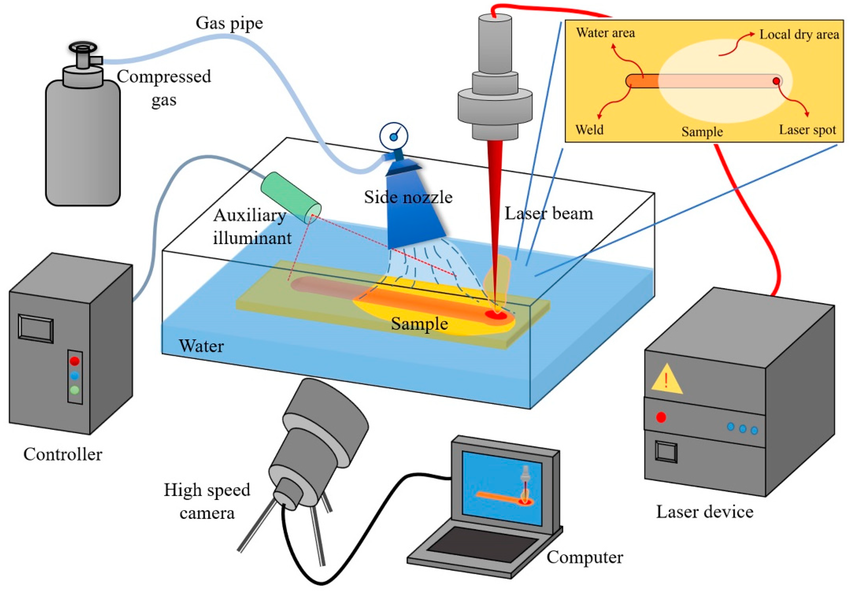
The experimental platform of underwater laser welding used in this paper is shown in Figure 1. It consists of a fiber laser, atmospheric pressure tank, side nozzle, high speed camera, welding robot, and so on. Concretely, the laser used in the experiment was the YLR-4000 fiber laser of the IPG Company (Oxford, MA, USA). The maximum output power was 4 kw, and the output laser wavelength was 1.07 μm. The laser beam can be transmitted through the optical fiber for long distance flexible transmission and focused on the condenser lens in the laser head. The laser spot diameter was 0.3 mm, and the focal length of the lens was 250 mm. For protecting the laser mirror the laser head was set to have an angle of 10° between the axial and vertical direction. The robot used in this paper was an ABB IRB4400 (Zurich, Switzerland) industrial robot with a maximum load of 60 kg and a repeat positioning accuracy of 0.07 mm. A phantom V611 high speed camera (Wayne, NJ, USA), with a maximum shooting speed of 69,000 FPS, was used. An auxiliary illuminant was used for eliminating the interference of other light during welding. Weld-on-plate was adopted for a more effective extrapolation to other welding methods. The local dry area was a circular area about 50 mm in diameter. The welding material was cp-Ti of 130 mm × 60 mm × 8 mm. The schematic diagram of the local dry area is shown in the illustration in the upper right corner of Figure 1.
In the experiment, experimental results were obtained by changing the welding speed and welding environment. The experimental parameters are shown in Table 1. Other parameters remained the same. The defocus was 0 mm. The total distance of the beam moving along the welding direction was 64 mm. The imaging speed of the high speed camera was 5000 FPS.
After welding, we cut cross-sections in the middle of the welds, then ground them layer by layer with sandpaper. Polishing was done with an aluminum trioxide abrasive. Kroll reagent was used to corrode the metallographic samples. Then, the samples were rinsed with water and ethanol immediately after the surface became gray and black. The morphology of the cross-section was recorded by Triocular Microscope SZX51 (Olympus Corporation, Tokyo, Japan). The microstructural was observed using an Ultra-Depth Three-Dimensional Microscope VHX-1000C (Keyence, Osaka, Japan). The Vickers hardness was recorded by a MH-3 microhardness tester (Mitutoyo, Kanagawa, Japan). The testing points were near the weld at 50 μm from the upper surface of the plate. The load was 300 g and the pressure holding time was 15 s. The distance of each test point of Process No.1–5 was 0.25 mm. While the distance of each test point of Process No.6 was 0.2 mm, for obtaining more characteristic points in the narrow seam area.
To obtain the average temperature curve of the center of the cross-section (0.5 mm × 0.5 mm) at the end of the seam, the method of numerical simulation was adopted. The welding simulation software InteWeld (V1.0, Wuhan, China) was used. The software is based on the finite element solution format of the thermo-elastic-plastic algorithm, which is widely recognized in the field of numerical simulation of welding [22,23]. The calculation of temperature field was based on a heat conduction equation and finite element method. By setting the convection heat transfer coefficient of different regions, the simulation of laser welding temperature field under the effect of an underwater environment was realized. For the underwater welding process, due to the influence of water vapor and local high pressure blowing, the convection heat transfer coefficient was set to 100 J/(m2·s·°C) in the local dry area (about 50 mm diameter, as shown in the insert of Figure 1) and 5000 J/(m2·s·°C) in the other regions. For the atmospheric environment, the convection heat transfer coefficient was set to 30 J/(m2·s·°C) in the welding shielding gas region and 15 J/(m2·s·°C) in the other regions. Paraview (Kitware, NY, USA) was adopted for post-processing.
3. Results and Discussion
3.1. Macro-Morphology
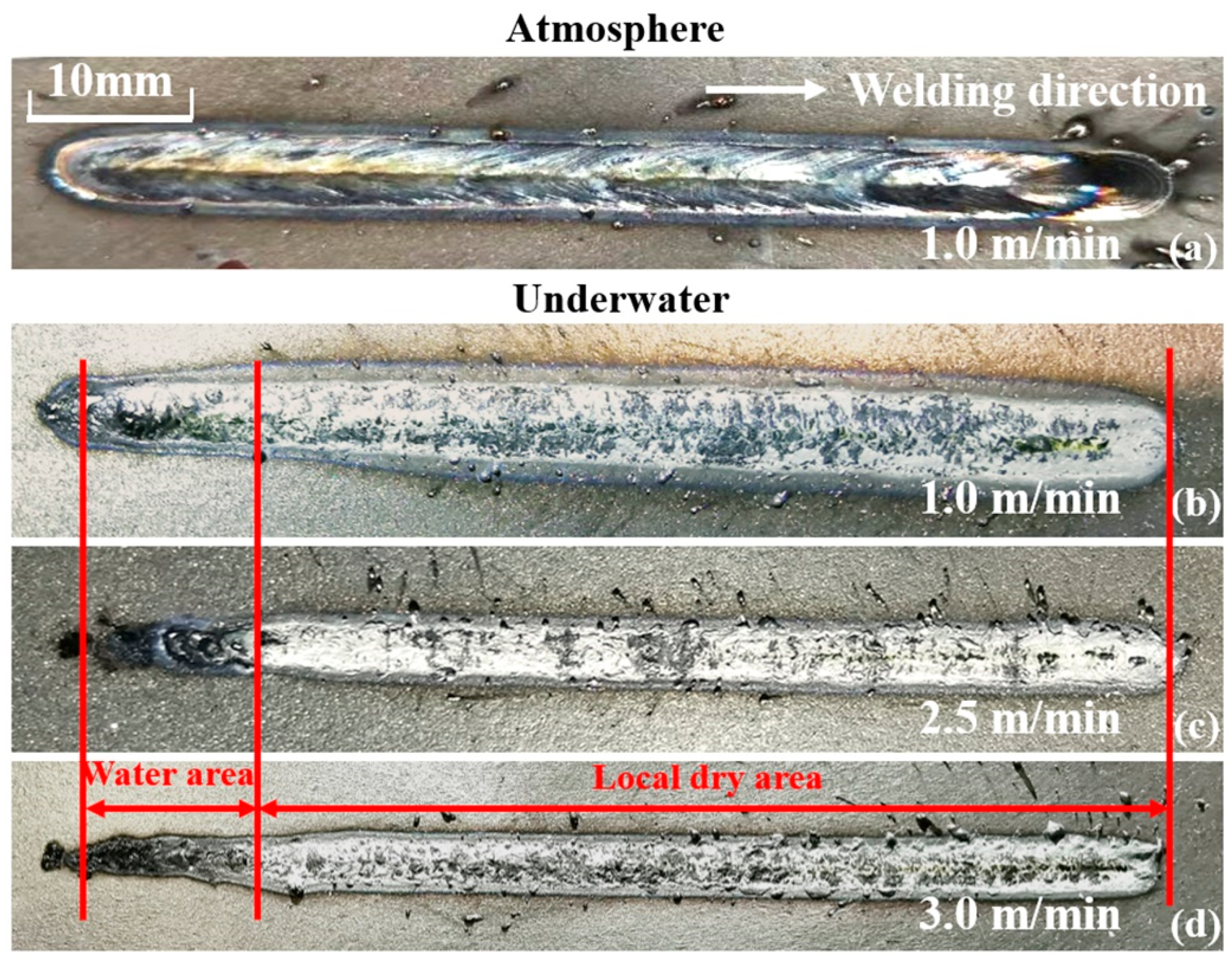
Figure 2 shows the macroscopic morphology of the surface on the weld. Figure 2a shows the weld in an atmospheric environment. Figure 2b–d shows the welds in a local dry underwater environment. It can be observed that irregular weld shape, burn-through, and even varying degrees of blackening appear at the starting position of underwater seams, and the weld width is also significantly reduced, along with a local incomplete penetration welded area. The above phenomenon may have been the combined result of a variation of laser focus caused by the disturbance of water and the accelerated oxidation effect caused by water dissociation. The appearance of the weld in the local dry area was not as glossy as that in the atmospheric environment, but the appearance was complete, with hardly any surface porosity and slag. Therefore, local dry underwater laser welding using air as an assisting gas is feasible. When the welding speed increased, the weld gradually became straight and flat. With the increase of welding speed, the degree of weld oxidation in local dry area seemed to decrease due to the decrease of local energy input. Similar results can be found in Guo, et al. [18] for reducing welding power.
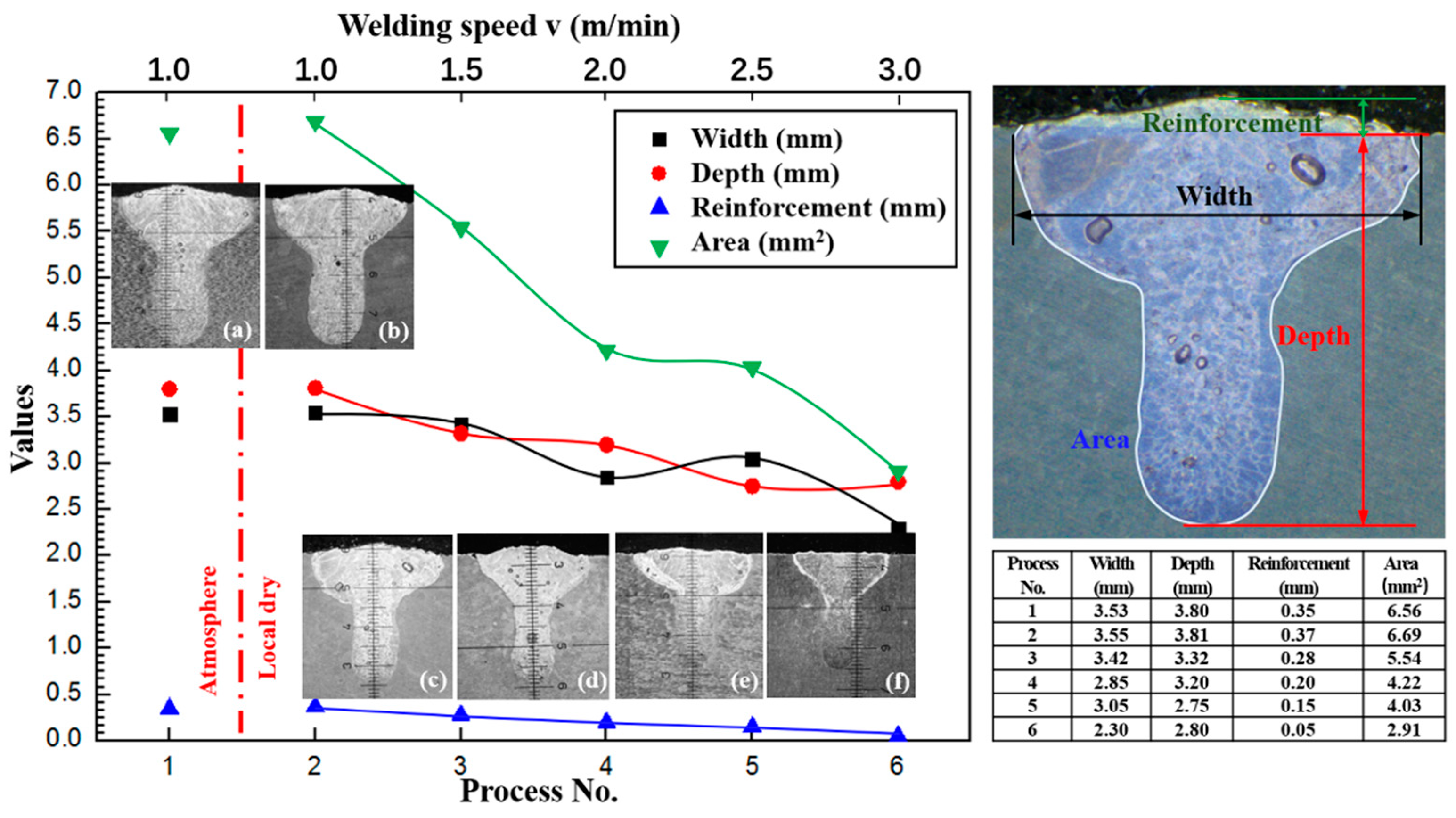
In addition, the morphology of the cross-section was analyzed, as shown in Figure 3. Comparing Process No. 1 and No. 2, it is found that the difference of depth and width of weld is within 1%, and the difference of area is within 2%. Due to the existence of experimental error, it is considered that the morphology of the weld cross-section obtained by underwater local dry laser welding was basically consistent with that obtained by ordinary laser welding. From Process No. 2 to No. 6, it can be seen that the depth and width of the fusion zone and the reinforcement slightly decreased with the increase of welding speed, and the cross-sectional area of the whole fusion zone also decreased. This is because, with the increase of welding speed, the heat input of the weld decreases, resulting in the reduction of the fusion area. This trend is consistent with the laser welding process in an ordinary atmospheric environment [21,24,25,26]. Therefore, compared with the weld of ordinary laser welding in an atmospheric environment, the air assisted underwater local dry laser welding process has little effect on the weld cross-section morphology, and the variation of weld morphology with energy input is the same as that of ordinary laser welding.
3.2. Microstructure
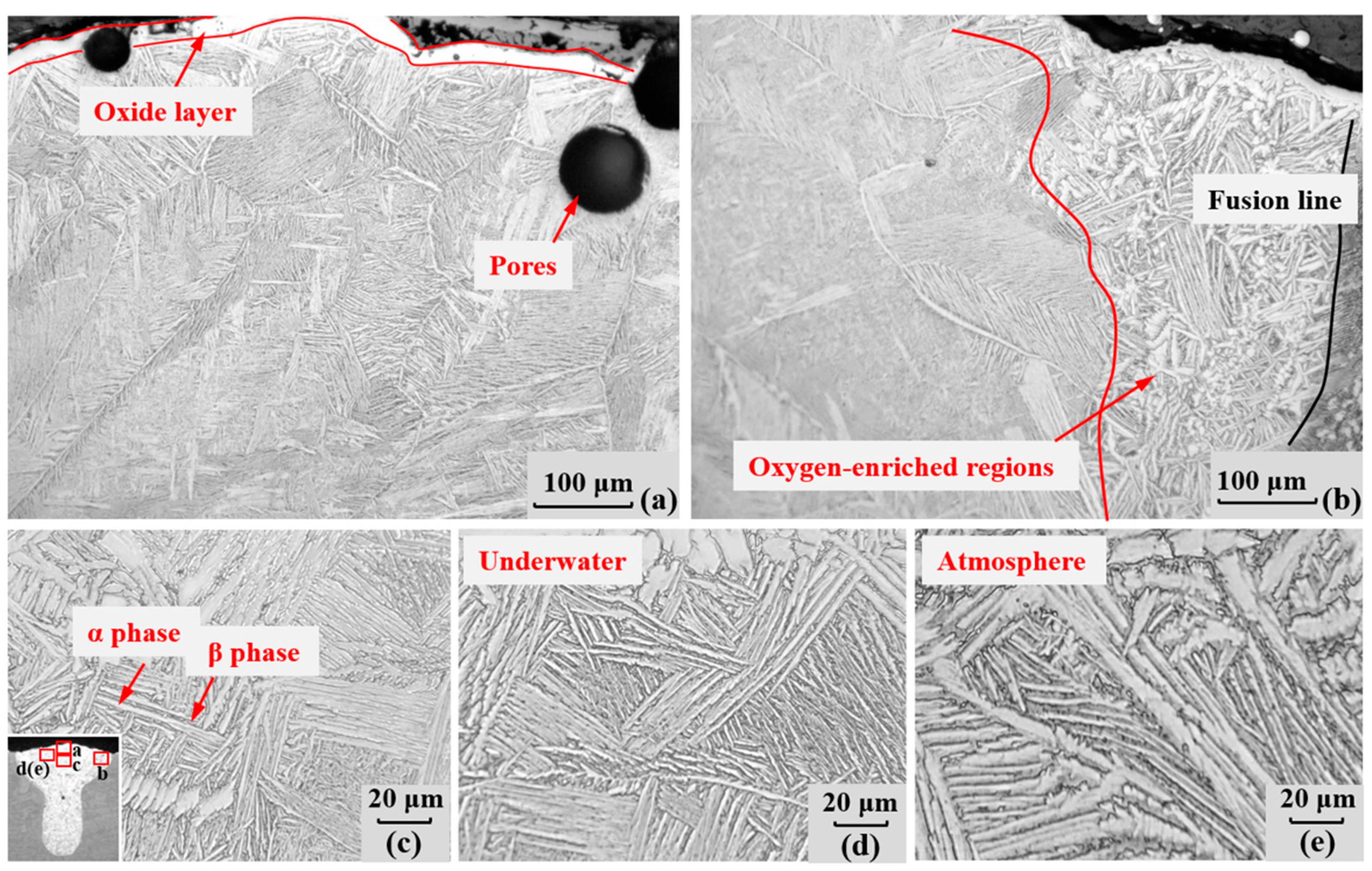
The local dry underwater laser welding process mainly affects the weld microstructure. In order to find out the influence of the underwater environment on the weld microstructure, a weld microstructure of 1 m/min in the local drainage area was observed, as shown in Figure 4a–d. To compare the results, the corresponding position of the weld microstructure for the atmospheric environment under the same process parameters is also presented in Figure 4e. Figure 4a shows the top area in the middle of the cross-section, Figure 4b shows the top area of the right side of the cross-section, and Figure 4c,d show the local magnification of the area near the top of the weld. In Figure 4a, it can be seen that there are some round pores in the weld. Some of the pores are nearly 100 μm in size. There is an oxide layer on the top surface of the weld, which is tens of microns thick. The weld is a combination of columnar crystal and equiaxed crystal. The columnar crystal inclines to the top of the weld centerline. The top region is dominated by irregular polygonal equiaxed crystals, and its internal microstructure is different from that of the columnar crystals below. Furthermore, it can be observed in Figure 4b that the microstructure near the top area on the right side of the weld, which indicates an oxygen-enriched region, is significantly different. The microstructure of the oxygen-enriched region is coarse α phase, of which the length-diameter ratio decreases significantly and the distribution is disordered.
In the weld, as shown in Figure 4c,d, there are long and thin α + β. According to the shape and distribution of the α strips, the morphology of Widmanstatten is parallel, cross, or mixed. In the process of laser welding, the overheated temperature makes α phase rapidly transform to β phase. Due to the rapid reduction of temperature below the transition temperature, β phase cannot completely transform into α phase. The β phase without phase transition will be coarsened during solidification, forming a coarse primary β grain. Then grain boundary α and bar α precipitate from the primary β grain boundary. Finally, needle-like α + β and primary β grain boundaries, or strip like α + β and primary β grain boundaries, are formed in the weld. Comparing the microstructure of the corresponding position of the weld, it can be seen that the acicular martensite was finer in the water than that in air, as shown in Figure 4d,e.
3.3. Oxidation Behavior of Underwater Weld
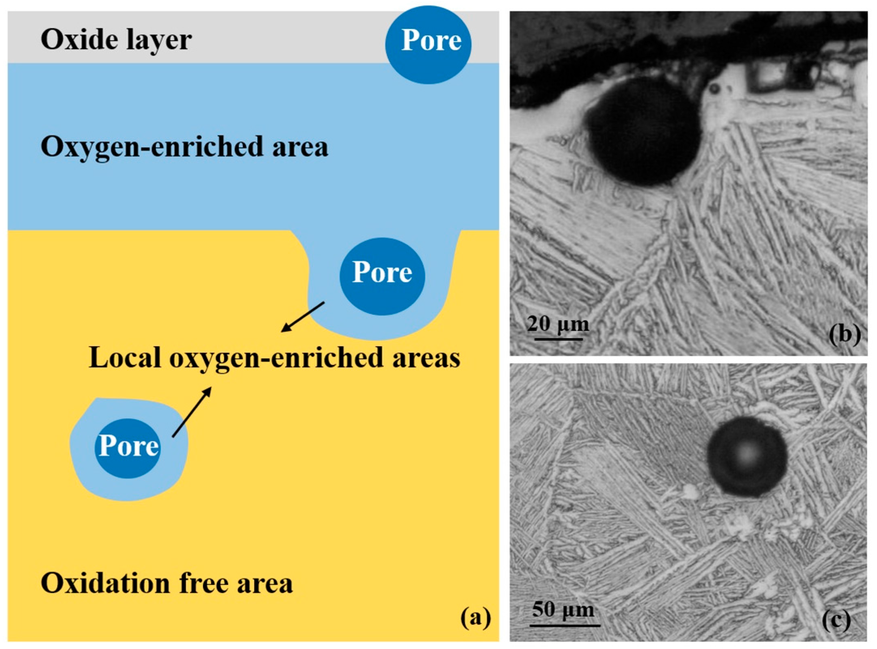
The weld of local dry underwater laser welding presents a three-layer structure of an oxide layer, an oxygen-enriched area, and an oxidation free area, as shown in Figure 5a. Underwater welding itself is in a high temperature and high pressure water vapor ambience, which provides rich hydrogen and oxygen ions, and local blowing for drainage can easily affect the flow of the molten pool and involve gas in the welding process, causing porosity defects in the weld. The pores in the oxide layer, which are shortcuts for oxygen ions to diffuse further into the weld, will cause the formation of oxygen-enriched areas, as in Figure 5a,b. In addition, the pores located deeper in the weld may lead to the formation of local oxygen-enriched areas in the weld area outside the oxygen-enriched areas, as shown in Figure 5a,c. Therefore, in underwater welding, high temperature and high pressure water vapor and local blowing are the direct causes of weld oxidation, while the porosity defects further aggravate the oxidation behavior. Therefore, reducing the heat input may reduce the weld oxidation by reducing the decomposition reaction of the water and oxidation reaction. Moreover, changing the blowing direction of the assisting gas, to improve the gas-liquid two phase flow, may be a possible method for reducing the effect of pore defects caused by blowing.
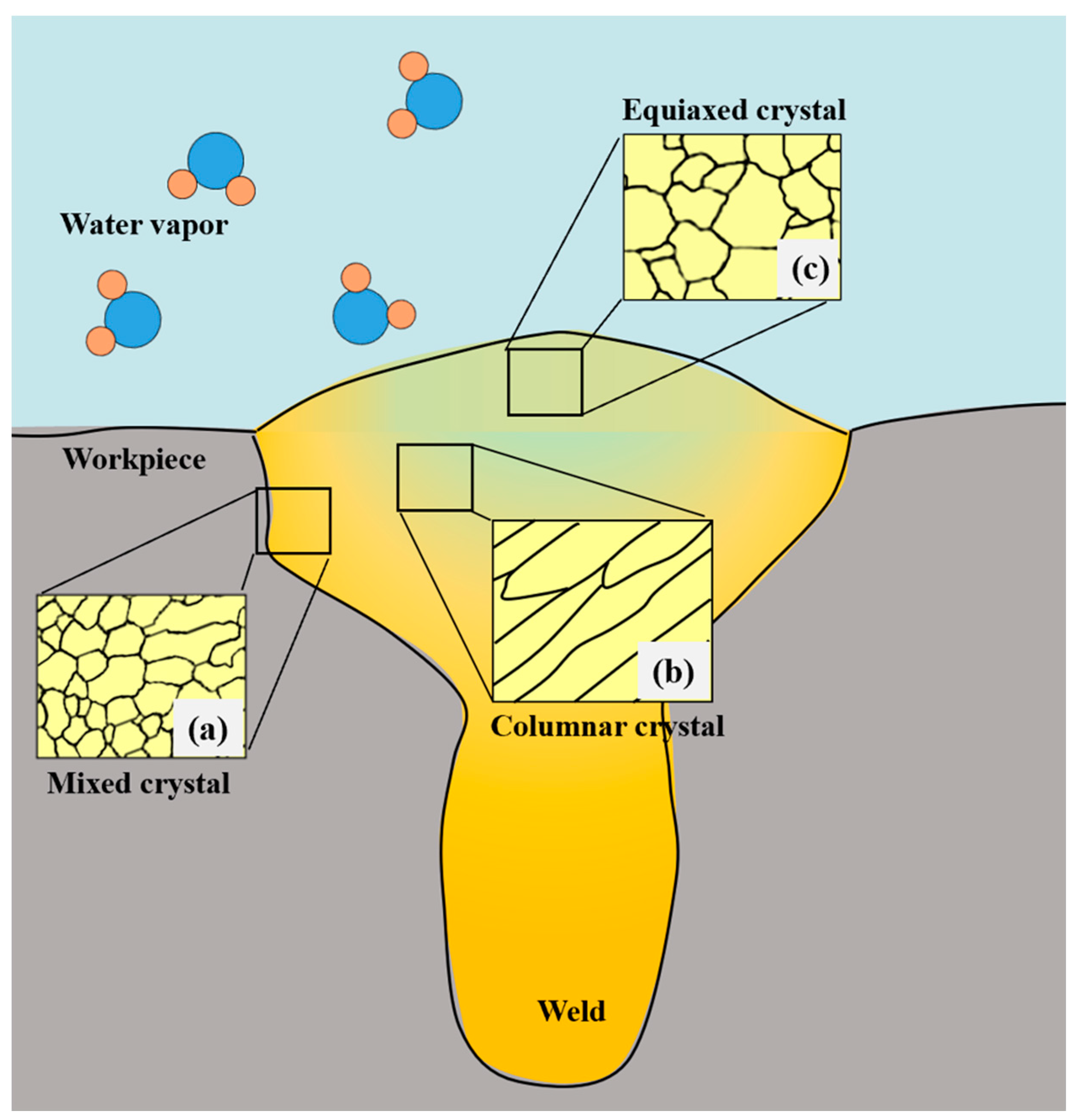
According to the microstructure of the weld, the oxygen-enriched areas were mostly concentrated in the top area of the weld center and near the fusion zone. When the weld solidified, the plate was subjected to water cooling; the cooling rate was fast, the undercooling degree was large, and a mixed crystal area with a large number of grain boundaries was formed, as in Figure 6a. However, due to the small temperature gradient and low cooling rate in the top area of the weld center equiaxed crystals formed easily, as in Figure 6c. Relative to the columnar crystal area in Figure 6b, there were many grain boundaries and phase boundaries near the fusion zone (Figure 6a) and the top area in the center of the weld (Figure 6c) due to the physical behavior of the weld solidification. Oxygen belongs to the stable element of α phase, which rapidly dissolves in α phase in large amounts. This will lead to the combination and growth of α grains and the formation of coarse grains. There are many grain boundaries and phase boundaries around the fusion zone and in the center of the weld, which are the diffusion channels for oxygen [27]. The oxidation resistance of the above area is relatively poor. The microstructure, α phase, of the oxygen-enriched regions above is blocky or flaky, extending from the surface of the weld into the interior. Therefore, the microstructure oxidation of underwater welds mainly occurs in the top area of the weld and fusion zone.
3.4. Hardening Behavior of Underwater Welds
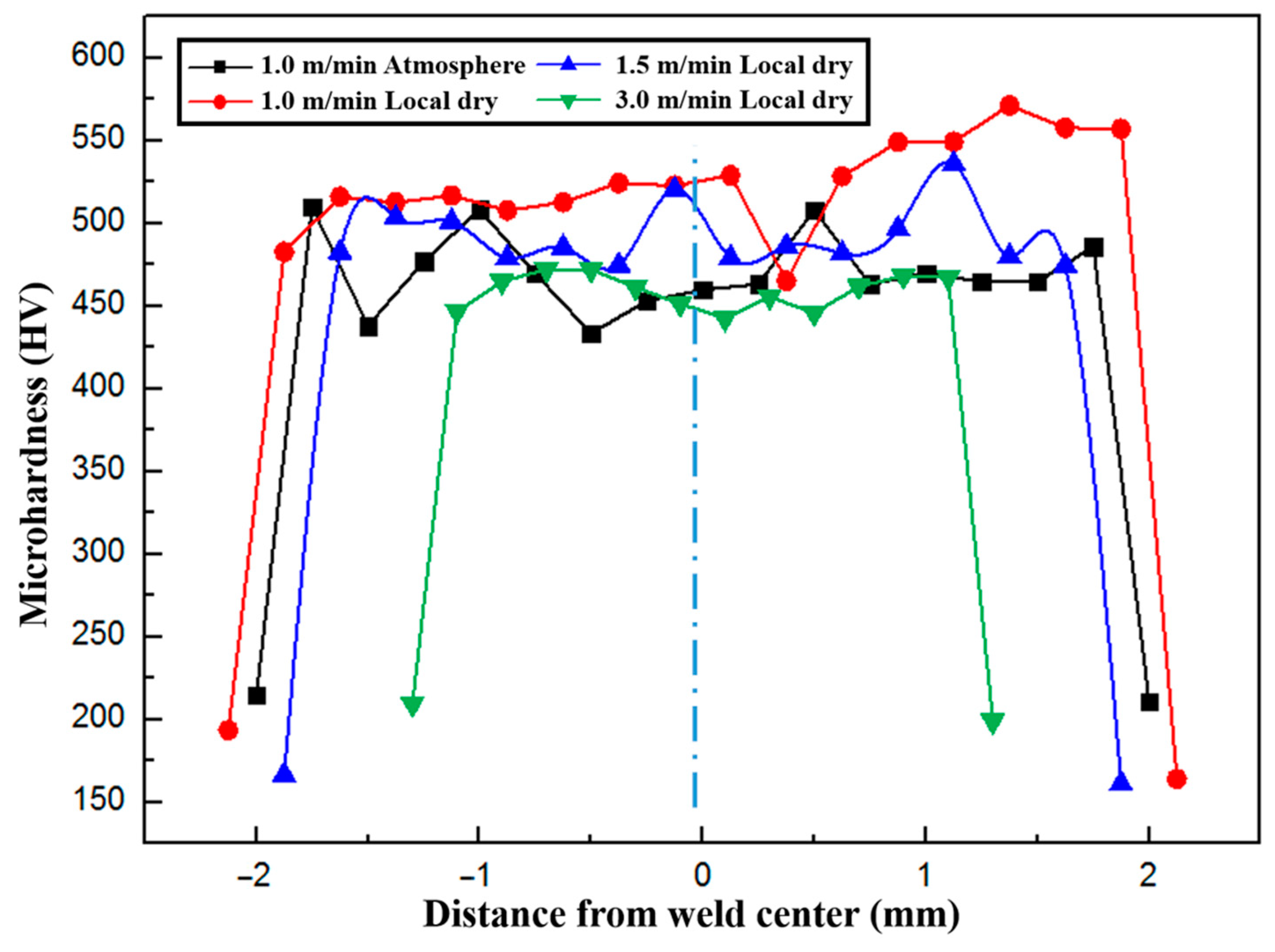
The mechanical properties of welds will be affected because of the change of the microstructure. The microhardness of the welds at a 50 μm distance from the upper surface of the plate in the underwater environment and in the atmospheric environment were measured. In Figure 7, the microhardness test results of a 1.0 m/min weld in atmosphere, and 1.0 m/min, 1.5 mm/min, and 3.0 m/min welds underwater are shown. The first and last measuring points of each set of data are located outside the weld fusion line. It can be seen that the microhardness of the weld area is obviously higher than that of the heat affected zone. By comparing the results of 1 m/min in different experimental environments, the microhardness of the weld in a water environment is seen to be higher than that in atmosphere. In addition, comparing the weld of local dry laser welding at different welding speeds, it can be found that the microhardness of the weld decreases with the increase of welding speed.
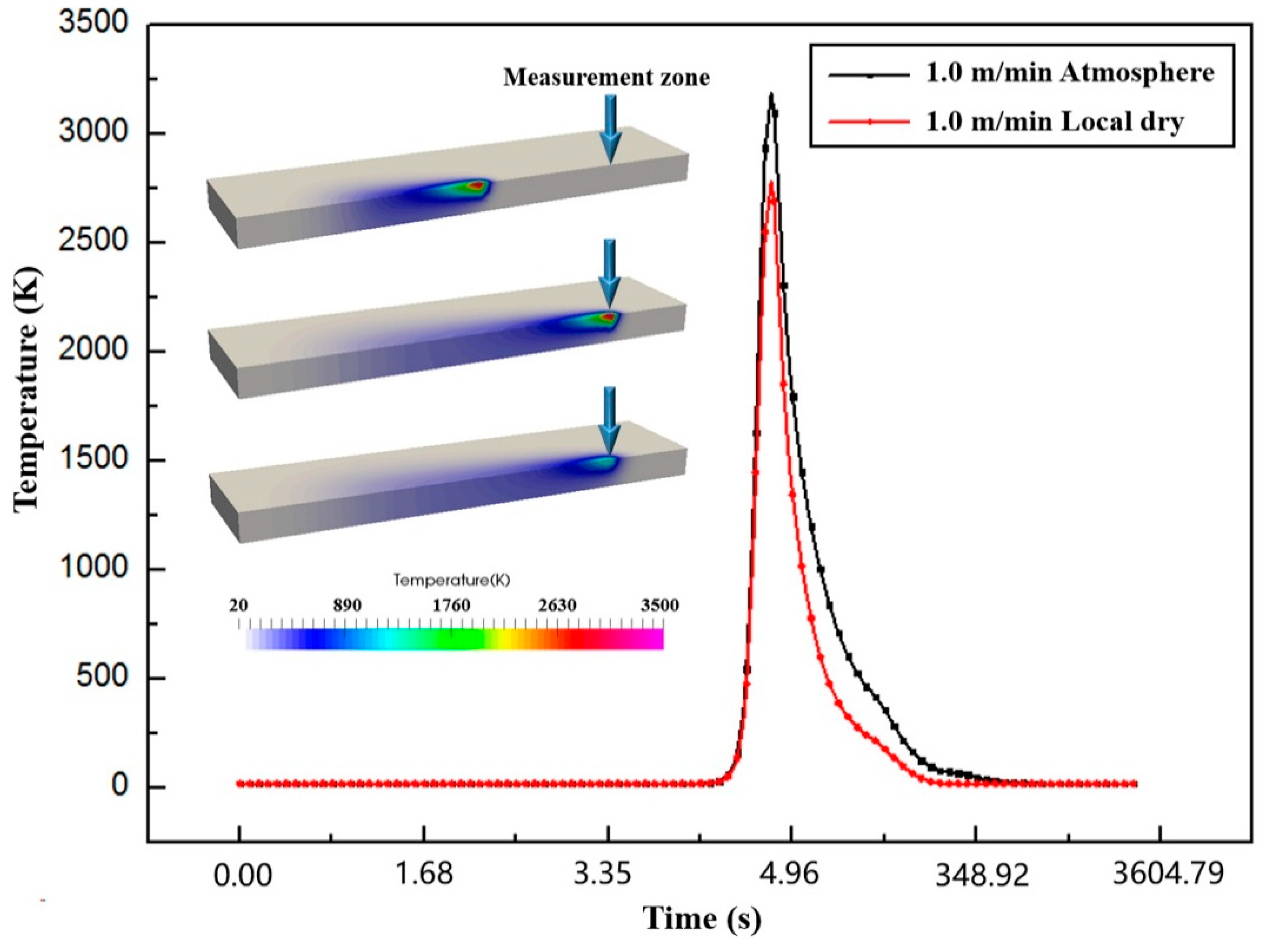
To find out the reason for the increase of microhardness of underwater welds, the average temperature versus time curve of the local area of weld section was measured. As shown in Figure 8, the peak of the regional average temperature of the underwater weld was around 2800 K, which was lower than the 3200 K in the atmospheric environment. In addition, the temperature of the underwater weld decreased faster. Although the water around the welding area was basically drained, the water-cooling effect will still affect the solid-state phase transformation process of the weld, and the weld surface will still be affected by high temperature water vapor due to the action of the laser. First, the supercooling effect will increase the microhardness overall by making the microstructure of the weld finer. Due to the effect of the water, the temperature gradient is larger. A larger temperature gradient leads to a higher cooling rate for molten pool, which increases the undercooling degree. The cooling rate of underwater welding exceeds that of ordinary laser welding in air. Therefore, when the molten pool is cooling, finer α phase precipitates from the β phase. The formation of a needle-like martensitic microstructure increases weld microhardness. Therefore, the supercooling effect in the water environment is considered to be an important cause of the increase of microhardness in the whole range of the seam.
In addition, the local oxidation microstructure of the weld greatly increases the local microhardness of the weld. The microstructure of the underwater weld showed a special coarse α phase, for which the length–diameter ratio decreased significantly, especially around the fusion zone and the top area of the weld center. Laser welding energy density is very high, which causes the titanium to be easily oxidized. At the same time, because of the local blowing, high temperature, and high pressure water vapor ambience, the weld is prone to oxidation, especially on the surface. The above factors will lead to weld oxidation, which will increase the microhardness of the weld.
The increase of the microhardness in the underwater welding may have been due to the hardening of the weld caused by oxygen and the acicular martensite produced by rapid cooling in the water environment. In addition, when the welding speed of underwater welding increases, the microhardness decreases. This is consistent with the changeable rule in an atmospheric environment, that with the increase of welding speed the heat input of the weld decreases, so the oxidation degree of the weld decreases. Although the effect of water, in rapid cooling and oxidation, will increase the microhardness of the weld, when the welding speed was increased to 3 m/min, the microhardness of the weld was almost the same as that in the atmospheric environment. Therefore, in an actual underwater environment, it is possible to realize air-assisted local dry underwater laser welding by adjusting process parameters.
4. Conclusions
In this paper, the morphology, microstructure, and microhardness of underwater local dry laser welding of cp-Ti, using air as an assisting gas, were systematically studied. The main conclusions are as follows:
- (1)
- The weld morphology of underwater local dry laser welding is smooth and slightly oxidized, which is better than that of underwater wet welding. With the increase of welding speed, the oxidation degree of the surface of the weld decreases due to the decrease of local energy input.
- (2)
- Compared with a weld with the same process parameters in atmosphere, the cross-section geometric morphology was almost unaffected by the special underwater welding environment. The variation law of the cross-section morphology was the same as that in ordinary atmosphere laser welding.
- (3)
- The weld of underwater local dry laser welding presents a three-layer structure of an oxide layer, an oxygen-enriched area, and an oxidation free area. High temperature and high pressure water vapor and local blowing are the direct causes of weld oxidation, and the porosity defects further aggravate the oxidation behavior. Reducing the heat input and adjusting the blowing direction of the assisting gas may reduce the weld oxidation.
- (4)
- The water environment will affect the solid-state phase transformation process, accelerate the cooling of the molten pool, and form fine acicular martensite. It will increase the overall microhardness of the weld in water. In addition, the oxygen enriched ambience is the cause of the increase in local microhardness.
- (5)
- With the increase of welding speed, the microhardness of a weld in water decreases. When the welding speed was increased to 3 m/min, the microhardness of the weld was almost the same as that in the atmospheric environment. In this way, local dry underwater laser welding with air assistance is a cost-effective method, which is promising for the in situ repair of large-scale underwater facilities.
Author Contributions
Conceptualization, S.P., M.L. and R.H.; methodology, M.L. and Q.L.; software, M.L.; validation, R.H.; formal analysis, M.L.; investigation, M.L.; writing—original draft preparation, M.L.; writing—review and editing, M.L., P.W., S.P., R.H., A.H. and Q.L.; supervision, P.W., S.P., R.H., A.H. and Q.L.; project administration, S.P., P.W. and A.H.; funding acquisition, S.P. and A.H. All authors have read and agreed to the published version of the manuscript.
Funding
This research was funded by National Key R&D Program of China, grant number 2017YFE0100100, and the National Natural Science Foundation of China (NSFC), grant number 51675202.
Institutional Review Board Statement
Not applicable.
Informed Consent Statement
Not applicable.
Data Availability Statement
Not applicable.
Conflicts of Interest
The authors declare no conflict of interest.
References
- Yoda, M.; Tamura, M.; Fukuda, T.; Shiihara, K.; Sudo, T.; Maehara, T.; Morishima, Y.; Kato, H.; Ichikawa, H. Underwater laser beam welding for nuclear reactors. In Proceedings of the 20th International Conference on Nuclear Engineering and the ASME 2012 Power Conference, Anaheim, CA, USA, 30 July–3 August 2012; pp. 191–195. [Google Scholar]
- Zhu, J.; Jiao, X.; Wang, K.; Gu, Y.; Cai, Z. Development of Underwater Laser Wire-Filling Welding Device and Welding Maintenance Technology for Offshore Oil and Gas Pipeline. In Offshore Technology Conference Asia, Proceedings of the Offshore Technology Conference, Kuala Lumpur, Malaysia, 2 November–19 August 2020; Offshore Technology Conference: Houston, TX, USA.
- Noack, J.; Vogel, A. Laser-induced plasma formation in water at nanosecond to femtosecond time scales: Calculation of thresholds, absorption coefficients, and energy density. IEEE J. Quantum Electron. 1999, 35, 1156–1167. [Google Scholar] [CrossRef] [Green Version]
- Bergmann, J.; Patschger, A.; Bastick, A. Enhancing Process Efficiency due to high Focusing with high Brightness Lasers-Applicability and constraints. Phys. Procedia 2011, 12, 66–74. [Google Scholar] [CrossRef] [Green Version]
- Brooks, R. Underwater Laser-Beam Welding Set for U.S. Debut. Weld. Des. Fabr. 2012, 4, 24. [Google Scholar]
- Zhang, X.; Chen, W.; Ashida, E.; Matsuda, F. Effect of shielding conditions on welding properties in underwater local-dry laser welding. Lasers in Material Processing and Manufacturing. Int. Soc. Opt. Photonics 2002, 4915, 97–106. [Google Scholar]
- Łabanowski, J.; Fydrych, D.; Rogalski, G. Underwater welding-a review. Adv. Mater. Sci. 2008, 8, 11–22. [Google Scholar] [CrossRef]
- Sepold, G.; Teske, K. Results of underwater welding with high power CO2 lasers. Int. Congr. Appl. Lasers Electro. Opt. 1983, 38, 87–89. [Google Scholar]
- Zhu, J.; Jiao, X.; Zhou, C.; Gao, H. Applications of Underwater Laser Peening in Nuclear Power Plant Maintenance. Energy Procedia 2012, 16, 153–158. [Google Scholar] [CrossRef] [Green Version]
- Habenicht, I.; Santos, J.; Szelagowski, P.; Franz, T. Development of a Nozzle for Underwater Laser Beam Welds; Process of Offshore Mechanics and Arctic Engineering III; American Society of Mechanical Engineers: New York, NY, USA, 1996; pp. 141–149. [Google Scholar]
- Jones, M. Underwater Laser Welding Nozzle. U.S. Patent US6060686 A, 9 May 2000. [Google Scholar]
- Yamashita, Y.; Kawano, T.; Mann, K. Underwater Laser Welding by 4 kW CW YAG Laser. J. Nucl. Sci. Tech. 2001, 38, 891–895. [Google Scholar] [CrossRef]
- Morita, I.; Owaki, K.; Yamaoka, H.; Kim, C. Study of Underwater Laser Welding Repair Technology. Weld. World 2006, 50, 37–43. [Google Scholar] [CrossRef]
- Bucurel, R.; Hlifka, G. Laser beam welding process automates underwater repairs. Weld. J. 2010, 89, 47–49. [Google Scholar]
- Zhang, X.; Chen, W.; Ashida, E.; Matsuda, F. Relationship between weld quality and optical emissions in underwater Nd: YAG laser welding. Opt. Laser Eng. 2004, 41, 717–730. [Google Scholar] [CrossRef]
- Luo, M.; Hu, R.; Li, Q.; Huang, A.; Pang, S. Physical understanding of keyhole and weld pool dynamics in laser welding under different water pressures. Int. J. Heat. Mass Transf. 2019, 137, 328–336. [Google Scholar] [CrossRef]
- Di, X.; Ji, S.; Cheng, F.; Wang, D.; Cao, J. Effect of cooling rate on microstructure, inclusions and mechanical properties of weld metal in simulated local dry underwater welding. Mater. Des. 2015, 88, 505–513. [Google Scholar] [CrossRef]
- Guo, N.; Cheng, Q.; Zhang, X.; Fu, Y.; Huang, L. Microstructure and mechanical properties of underwater laser welding of titanium alloy. Materials 2019, 12, 2703. [Google Scholar] [CrossRef] [PubMed] [Green Version]
- Çolak, Z.; Ayan, Y.; Kahraman, N. Weld morphology and mechanical performance of marine structural steel welded underwater in a real marine environment. Int. J. Adv. Manuf. Tech. 2020, 109, 491–501. [Google Scholar] [CrossRef]
- Hu, Y.; Shi, Y.; Sun, K.; Shen, X.; Wang, Z. Microstructure and mechanical properties of underwater hyperbaric FCA-welded duplex stainless steel joints. J. Mater. Process. Tech. 2018, 261, 31–38. [Google Scholar] [CrossRef]
- Fu, Y.; Guo, N.; Zhu, B.; Shi, X.; Feng, J. Microstructure and properties of underwater laser welding of TC4 titanium alloy. J. Mater. Process. Tech. 2020, 275, 116372. [Google Scholar] [CrossRef]
- Ueda, Y.; Yamakawa, T. Analysis of thermal elastic plastic stress and strain during welding by finite element method. Trans. Jpn. Weld. Soc. 1971, 2, 90–100. [Google Scholar]
- Liang, L.; Hu, R.; Wang, J.; Luo, M.; Huang, A.; Wu, B.; Pang, S. A CFD-FEM Model of Residual Stress for Electron Beam Welding Including the Weld Imperfection Effect. Metall. Mater. Trans. A 2019, 50, 2246–2258. [Google Scholar] [CrossRef]
- Li, C.; Ding, Y.; Fu, G.; Li, X.; Jiang, J. Effect of fiber Laser–MIG hybrid process parameters on weld bead shape and tensile properties of commercially pure titanium. Mater. Manuf. Process. 2010, 25, 1309–1316. [Google Scholar] [CrossRef]
- Cui, L.; Bin, L.; Wu, Z.; Qi, X.; Ye, B.; Wang, A. Stitch welding of Ti–6Al–4V titanium alloy by fiber laser. Trans. Nonferrous Met. Soc. China 2017, 27, 91–101. [Google Scholar]
- Kim, J.; Ki, H. Scaling law for penetration depth in laser welding. J. Mater. Process. Technol. 2014, 214, 2908–2914. [Google Scholar] [CrossRef]
- Katsman, A.; Grabke, H.; Levin, L. Penetration of oxygen along grain boundaries during oxidation of alloys and intermetallics. Oxid. Met. 1996, 46, 313–331. [Google Scholar] [CrossRef]
Figure 1.
Schematic diagram of the underwater laser welding experimental platform.

Figure 2.
Macroscopic morphology of the surface on the welds. (a) 1.0 m/min, atmosphere; (b) 1.0 m/min, underwater; (c) 2.5 m/min, underwater; (d) 3.0 m/min, underwater.
Figure 2.
Macroscopic morphology of the surface on the welds. (a) 1.0 m/min, atmosphere; (b) 1.0 m/min, underwater; (c) 2.5 m/min, underwater; (d) 3.0 m/min, underwater.

Figure 3.
Characteristic morphology of weld cross-sections. (a) 1.0 m/min, atmosphere; (b) 1.0 m/min, underwater; (c) 1.5 m/min, underwater; (d) 2.0 m/min, underwater; (e) 2.5 m/min, underwater; (f) 3.0 m/min, underwater.
Figure 3.
Characteristic morphology of weld cross-sections. (a) 1.0 m/min, atmosphere; (b) 1.0 m/min, underwater; (c) 1.5 m/min, underwater; (d) 2.0 m/min, underwater; (e) 2.5 m/min, underwater; (f) 3.0 m/min, underwater.

Figure 4.
Microstructure of cross-sections in laser welding of 1.0 m/min (Process No. 2 and 6). (a) Top area in the middle; (b) Top area of the right side; (c) Near the top of the axis of the weld; (d) Near the left area of the top of the axis of the weld; (e) A counterpoint of (d) in atmosphere.
Figure 4.
Microstructure of cross-sections in laser welding of 1.0 m/min (Process No. 2 and 6). (a) Top area in the middle; (b) Top area of the right side; (c) Near the top of the axis of the weld; (d) Near the left area of the top of the axis of the weld; (e) A counterpoint of (d) in atmosphere.

Figure 5.
Schematic illustration of the oxidation behavior of local dry underwater welds. (a) Three-layer structure near the weld oxidation area; (b) the pores at the oxide layer; (c) the pores located outside the oxygen-enriched area.
Figure 5.
Schematic illustration of the oxidation behavior of local dry underwater welds. (a) Three-layer structure near the weld oxidation area; (b) the pores at the oxide layer; (c) the pores located outside the oxygen-enriched area.

Figure 6.
The difference in geometry of the grain in the weld leads to differential oxidation. (a) Mixed crystal; (b) columnar crystal; (c) equiaxed crystal.
Figure 6.
The difference in geometry of the grain in the weld leads to differential oxidation. (a) Mixed crystal; (b) columnar crystal; (c) equiaxed crystal.

Figure 7.
Microhardness of the weld.

Figure 8.
Average temperature curve of the cross-section of the weld.


Table 1.
The investigated laser welding parameters.
| Process No. | Power P (kW) | Welding Speed v (m/min) | Raw Water Depth D (mm) | Welding Environment |
|---|---|---|---|---|
| 1 | 3 | 1.0 | 0 | Atmosphere |
| 2 | 3 | 1.0 | 2 | Local dry |
| 3 | 3 | 1.5 | 2 | Local dry |
| 4 | 3 | 2.0 | 2 | Local dry |
| 5 | 3 | 2.5 | 2 | Local dry |
| 6 | 3 | 3.0 | 2 | Local dry |
Publisher’s Note: MDPI stays neutral with regard to jurisdictional claims in published maps and institutional affiliations. |
© 2021 by the authors. Licensee MDPI, Basel, Switzerland. This article is an open access article distributed under the terms and conditions of the Creative Commons Attribution (CC BY) license (https://creativecommons.org/licenses/by/4.0/).
Share and Cite
MDPI and ACS Style
Luo, M.; Wei, P.; Li, Q.; Hu, R.; Huang, A.; Pang, S. Underwater Laser Welding of Pure Ti: Oxidation and Hardening Behaviors. Metals 2021, 11, 610. https://doi.org/10.3390/met11040610
AMA Style
Luo M, Wei P, Li Q, Hu R, Huang A, Pang S. Underwater Laser Welding of Pure Ti: Oxidation and Hardening Behaviors. Metals. 2021; 11(4):610. https://doi.org/10.3390/met11040610
Chicago/Turabian StyleLuo, Manlelan, Pengyu Wei, Quanhong Li, Renzhi Hu, Anguo Huang, and Shengyong Pang. 2021. "Underwater Laser Welding of Pure Ti: Oxidation and Hardening Behaviors" Metals 11, no. 4: 610. https://doi.org/10.3390/met11040610
Note that from the first issue of 2016, this journal uses article numbers instead of page numbers. See further details here.