
Power Transfer Analysis of an Asymmetric Wireless Transmission System Using the Scattering Parameters


Department of Power, Electronic and Telecommunication Engineering, Faculty of Technical Sciences, University of Novi Sad, Novi Sad 21000, Serbia
*
Author to whom correspondence should be addressed.
Electronics 2021, 10(8), 906; https://doi.org/10.3390/electronics10080906
Submission received: 17 March 2021
/
Revised: 31 March 2021
/
Accepted: 5 April 2021
/
Published: 10 April 2021
(This article belongs to the Section Power Electronics)
Abstract
:The most widely adopted category of the mid-range wireless power transmission (WPT) systems is based on the magnetic resonance coupling (MRC), which is appropriate for a very wide range of applications. The primary concerns of the WPT/MRC system design are the power transfer capabilities. Using the scattering parameters based on power waves, the power transfer of an asymmetric WPT/MRC system with the series-series compensation structure is studied in this paper. This approach is very convenient since the scattering parameters can provide all the relevant characteristics of the WPT/MRC system related to power propagation. To maintain the power transfer capability of the WPT/MRC system at a high level, the scattering parameter is used to determine the operating frequency of the power source. Nevertheless, this condition does not coincide with the maximum possible power transfer efficiency of the system. In this regard, the WPT/MRC system is thereafter configured with a matching circuit, whereas the scattering parameter S21’is used to calculate and then adjust the matching frequency of the system. This results in the maximum available power transfer efficiency and thereby increases the overall performance of the system. Theoretical investigations are followed by numerical simulation and experimental validation.
1. Introduction
Wireless power transmission (WPT) is an emerging technology that has been studied since the work of Tesla and his ideas for wireless transmission [1]. Up to now, WPT has drawn a lot of attention, while much research has been devoted to improving power transfer capability (PTC) and power transfer efficiency (PTE), including transmission range. It is expected that the WPT will be used on a bigger scale in the times to come.
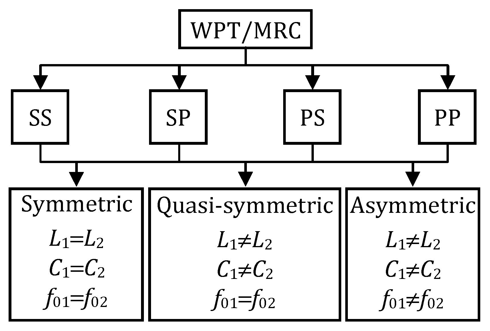
The most popular WPT method is based on the concept of inductive coupling. Since the WPT via magnetic resonance coupling (MRC) was reported in [2], it has attracted researches more than ever before. WPT/MRC is a system that operates at resonance to make the circuit behave as the purely resistive. In many publications, one can find WPT/MRC as a category of inductive power transfer (IPT) [3] called resonant inductive power transfer [4]. The main advantage of the WPT/MRC system over the well-known IPT is a higher PTE. This advantage has provided the implementation of the WPT/MRC systems not only in low-power devices [5,6,7], but also in high-power applications, such as electric vehicle charging solutions [8,9]. In order to increase the PTE at the medium distance, resonant coils (resonant relays) were introduced. Therefore, WPT/MRC system may consist of one or more resonant coils. With regard to the compensation topology, two-coil WPT/MRC systems are categorized as series-series (SS), series-parallel (SP), parallel-series (PS), or parallel-parallel (PP) compensated systems as shown in Figure 1. In addition, few hybrid compensation topologies have been introduced [3]. Based on the transmitter and receiver parameters, the WPT/MRC systems are categorized as symmetric, quasi-symmetric, and asymmetric (Figure 1). The symmetric system is composed of identical coils (inductances and ) and compensation capacitors (capacitances and ), which results in the same resonant frequencies ( and ) on transmitter and receiver sides. In a quasi-symmetric system, the transmitter and receiver have also the same resonant frequency, but they consist of non-identical coils and capacitors. The difference between quasi-symmetric and asymmetric systems is that the transmitter and receiver of the asymmetric system do not have the same resonant frequencies.
Numerous studies of symmetric and quasi-symmetric systems have been reported in the literature over the years. The operating frequency of such systems is equal to the resonant frequency in the under-coupled and critical-coupled regime. In the over-coupled regime, however, the transmitting power at the resonant frequency is significantly reduced; thus, the operating frequency needs to be adopted to provide the maximum PTC [10]. The frequency splitting phenomena, caused by the over-coupled regime, has a significant influence on the PTC and has been widely studied [11,12,13].
Many techniques for tracking and eliminating issues of the frequency splitting have been proposed. In [14,15], the analysis of frequency splitting and the PTE of two-coil and four-coil systems have been reported. In [14], a symmetric system has been analysed in terms of voltage gains and output power. With regard to the PTE, defined as the ratio of load power and available source power, an optimal ratio of load and source resistances has been investigated, keeping the original resonant frequency. However, matching circuit between the source and the system, which provides the flow of available source power to the system, has not been considered. The similar analysis has been reported in [15], but for a four-coil system.
To overcome issues of the over-coupled regime, a new WPT/MRC method based on splitting frequencies is proposed in [16]. The power transfer performances have been investigated theoretically and experimentally. Yet, only the symmetric system has been discussed. In the case of different quality factors of the transmitter and the receiver, the exact calculation of splitting frequencies is rather complex [16].
With the aim of increasing the PTE of the quasi-symmetric system, a mixed-resonant structure (with the shunt capacitor added in the SS circuit arrangement) has been proposed in [17]. The scattering parameter has been used for the analysis of the PTE and critical coupling factor derivation of the quasi-symmetric system (also valid for the symmetric system). In an effort to eliminate the frequency splitting, researchers have also proposed other topologies of the quasi-symmetric system, such as the circuit structure based on non-identical transmitting and receiving coils [18,19]. The authors in [18] have used appropriate coil configuration in a mixed-resonant structure of the WPT/MRC to eliminate frequency splitting, while the magnitude of the scattering parameter has been used to calculate and analyse the PTE. However, without the matching circuit between the source and the system, the PTE cannot be directly calculated from the scattering parameter. Likewise, in [19], a pair of non-identical transmitting and receiving coils has been proposed as an approach to avoid the over-coupled regime.
Nowadays, the diversity of wirelessly charged electrical consumer devices [20,21,22,23,24,25,26,27] requires greater focus on asymmetric WPT/MRC systems. Unlike the symmetric and quasi-symmetric systems that are well studied and reported in the literature, the analysis of the asymmetric circuits is more complex and more challenging. Much less research has been carried out on the asymmetric structure. The analysis resulting from symmetric cases cannot be used straightforwardly for the system with asymmetric structure as they will not be accurate enough [28]. Therefore, the calculation and selection of the asymmetric system’s operating frequency depends on system parameters, which need to be optimized [29]. Having this in mind, this paper aims to establish further theoretical research on the asymmetric WPT/MRC system and provide solutions for the maximum PTC and PTE of the proposed system.
Compared with the recent researches discussed above, which are mainly dedicated to the symmetric and quasi-symmetric systems, this paper focuses on the power transfer analysis of the two-coil WPT/MRC asymmetric system with the SS compensation topology. Herein, the traditional impedance (Z) parameters approach is not quite appropriate for the comprehensive characterization of WPT/MRC systems since it is difficult to involve frequency-dependent parasitic effects associated with the circuit components. Therefore, the concept of scattering (S) parameters is introduced as it can provide all the relevant characteristics of the WPR/MRC system related to power transfer. These parameters describe the electrical behaviour of the entire system (parasitic effects are included), thus greatly simplifying the power transfer analysis of the system under test. What is more, the S-parameters can be easily and accurately obtained by a vector network analyser (VNA), which is an additional benefit of the proposed approach. Using the electric circuit theory and the concept of the S-parameters, the model of the asymmetric WPT/MRC system is derived. The model is used to determine the operating frequency of the system to provide higher power transferred to the load, thus increasing the PTC of the system. It is shown that, for the characterisation of the PTC, the scattering parameter S21 is of paramount importance. By using the impedance matching circuit, the power transfer performance of the asymmetric WPT/MRC system can be greatly improved. Having determined the matching frequency and assuming that the system is matched to the power source, input power to the asymmetric WPT/MRC system will be equal to the available source power, and it will be transmitted to the load with the maximum possible PTE the system can provide. Using the concept of the S-parameters based on the power waves, the PTE of the system can be calculated effectively, by squaring the magnitude of the generalised scattering parameter . Lastly, the theoretical investigations are verified by numerical simulations and experimental results.
The remainder of this paper is organized as follows. In Section 2, the theoretical analysis of the asymmetric system is introduced, followed by the PTC and PTE analyses using the generalized S-parameters concept. In Section 3, the theoretical investigations are validated by numerical simulations, followed by experimental tests on the prototype of the two-coil asymmetric WPT/MRC system with the SS compensation structure. Finally, the conclusion is drawn in Section 4. Appendix A provides appropriate mathematical explanations related to Section 2, while the methodology for the recalculation of the S-parameters for an arbitrary normalisation impedance is presented in Appendix B.
2. Theoretical Analysis of the Asymmetric WPT/MRC System
The two-coil WPT/MRC asymmetric system consists of two electromagnetic subsystems with different resonant frequencies (Figure 1). In order to improve PTC and PTE of the WPT system, the compensation circuit is required in both transmitter and receiver sides [30]. The selection of adequate compensation topology depends on a given range of applications. This paper focuses on the SS compensation structure of the two-coil WPT/MRC asymmetric system, although the analysis concept is also valid for any compensation topologies.
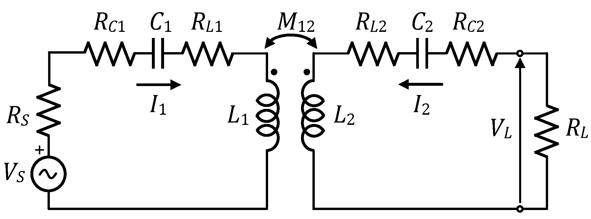
The equivalent circuit of the two-coil SS compensated WPT/MRC asymmetric system is shown in Figure 2. The system consists of the transmitting coil inductor and its series-connected compensation capacitor . On the receiver side, the compensation capacitor is series-connected with the receiving coil inductor . Mutual inductance between these two coils is denoted as . Here, , , and , represent equivalent series resistances associated with transmitting and receiving coils and compensation capacitors, respectively, while the distributed parasitic capacitance of the coils can be included in the compensation capacitance. AC voltage source , with the inner impedance , supplies the primary side (transmitter resonator), while the voltage of the load on the secondary side is denoted as . For the sake of simplicity, and without much loss of generality, it is adopted that the source and the load impedances are purely resistive.
2.1. PTC Analysis of the WPT/MRC System
The analytical model of the asymmetric WPT/MRC system is of key importance for the power transfer performance analyses. Many theories have been adopted in the literature. The equivalent lumped-element circuit model depicted in Figure 2 is described using the electric circuit theory with the Z-parameters. This is a common approach at low frequencies. At higher operating frequencies, however, these parameters are not well suited to characterize WPT/MRC system because it is difficult to perform their measurements. Parasitic effects of the circuit components limit their efficient use. Therefore, the concept of S-parameters is much more convenient. The S-parameters describe correlations of a new set of variables in terms of forward and backward waves, rather than their terminal variable values. In the literature, the S-parameters are usually based on voltage and current travelling waves [31,32,33,34]. This description is practical, since the S-parameters can be easily and accurately measured by the VNA [17]. In this paper, however, the concept of the S-parameters based on the power waves [35,36,37] is adopted. This approach is more preferred herein, due to its usefulness for the power propagation analysis [31,32], as well as the observation of the frequency splitting phenomena [19].
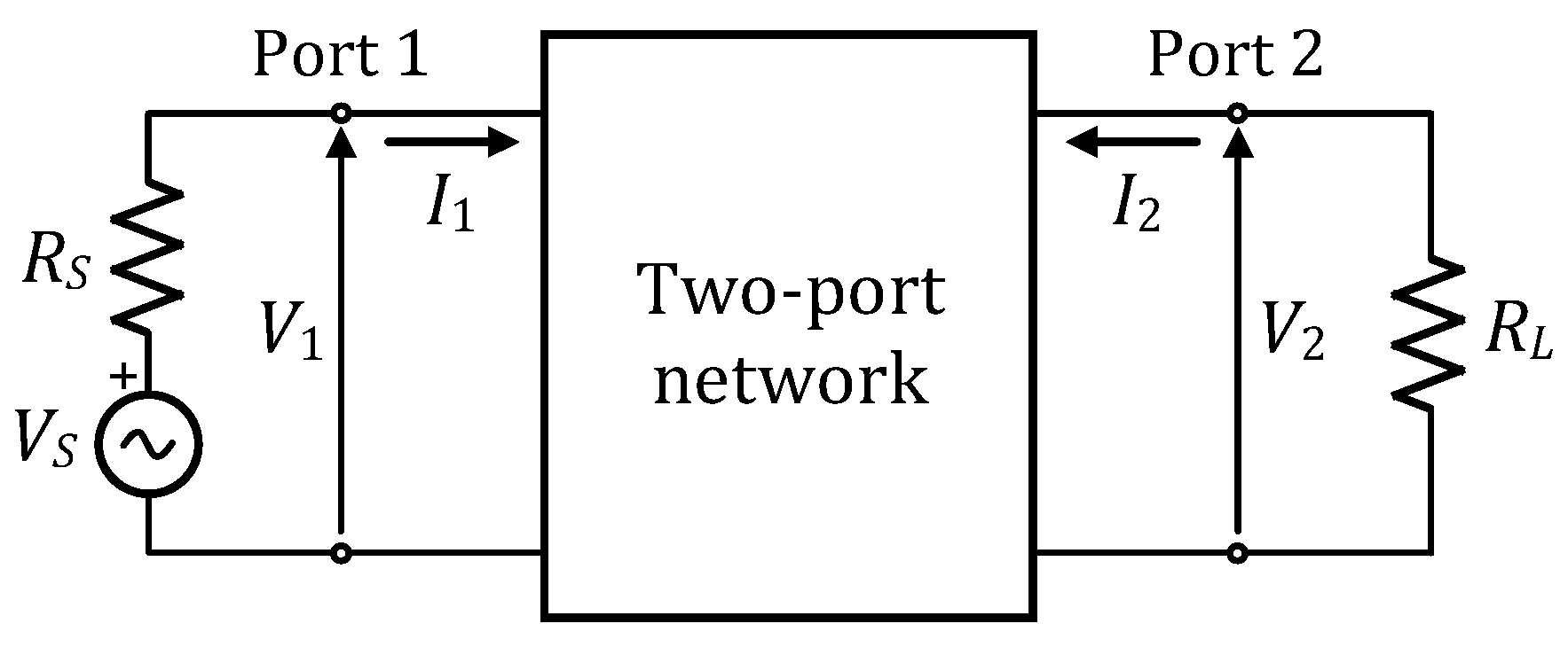
The equivalent lumped-element circuit model from Figure 2 can be represented as a passive linear two-port network with the S-parameters, as shown in Figure 3.
The conversion of the -parameter matrix into the generalized -parameter matrix can be done by transformation [35,38]:
where represents the reference impedance matrix used for the normalisation process (symbol * denotes complex conjugate). Based on Equation (1), it is also possible to convert S-parameters into Z-parameters representation. The appropriate transformation can be obtained by rearranging Equation (1) and is provided in [35].
For the two-port network from Figure 3, matrices in Equation (1) have the following general forms:
where and are reference impedances for Port 1 and Port 2, respectively. In the following analysis it is assumed to be (for Port 1) and (for Port 2), i.e., real-valued reference impedances are selected for the normalisation process.
The S-parameters can provide valuable performance information on energy transmission through the WPT/MRC network. Among all S-parameters (, , , ), the parameter is of particular importance. This parameter is the figure of merit in regards to the PTC since it is commonly used to describe the frequency splitting phenomena and the power delivered from Port 1 to Port 2 of the WPT/MRC system (Figure 3). Generally, the PTC is a function of the squared magnitude of the parameter, i.e., represents the normalised load power (load power scaled by the available power of the source). Hence, a higher value of leads to higher power transferred to the load.
By rearranging Equations (1)–(5), the S21 parameter can be expressed in terms of the Z-parameters as:
In order to find the frequency at which reaches the maximum value, the following equation has to be solved:
where is the operating angular frequency (S-parameters are frequency-domain quantities). The Equation (7) has a bi-quartic form and can be solved using the Kulkarni method [39,40], with the previous reduction to the quartic equation form by introducing the auxiliary variable , where :
Coefficients in Equation (8) are as follows:
where:
and and are resonant angular frequencies of the transmitter and the receiver sides, respectively. Coefficients in Equations (13)–(16) are expressed in terms of the frequency asymmetry factor (), loaded quality factors of the transmitter and the receiver ( and , respectively), and the coupling coefficient () between the two coils. These factors provide more information about the transmitter and receiver sides including their asymmetry, in contrast to lumped-elements.
As far as solutions of Equation (8) are concerned, only real- and positive-valued solutions can be selected. Therefore, there are two scenarios: either there is only one real- and positive-valued solution (), or there are three different real- and positive-valued solutions (, , and ) of Equation (8). In the first case, there is only one angular frequency (), which is actually the operating angular frequency of the power source. It is obvious that the WPT/MRC system is not in the over-coupled regime. However, in the second case, the frequency splitting phenomena occurs, i.e., the WPT/MRC system is in the over-coupled regime. One has to calculate the magnitude of the parameter for all three angular frequencies (, , ) and to select the one at which the magnitude of the parameter reaches the maximum value. Thereafter, the operating angular frequency of the power source is tuned to the previously selected one. Remaining angular frequencies correspond to a local minimum and a local maximum of the magnitude, and are not of interest. Detailed expressions of the solutions of Equation (8), including coefficients in Equations (10)–(12), are listed in Appendix A. One important note to keep in mind, however, is that in the previous analysis, does not represent the PTE of the WPT/MRC system. In other words, without the matching circuit, the maximum value of the will not provide the maximum PTE of the system.
2.2. PTE Analysis of the WPT/MRC System
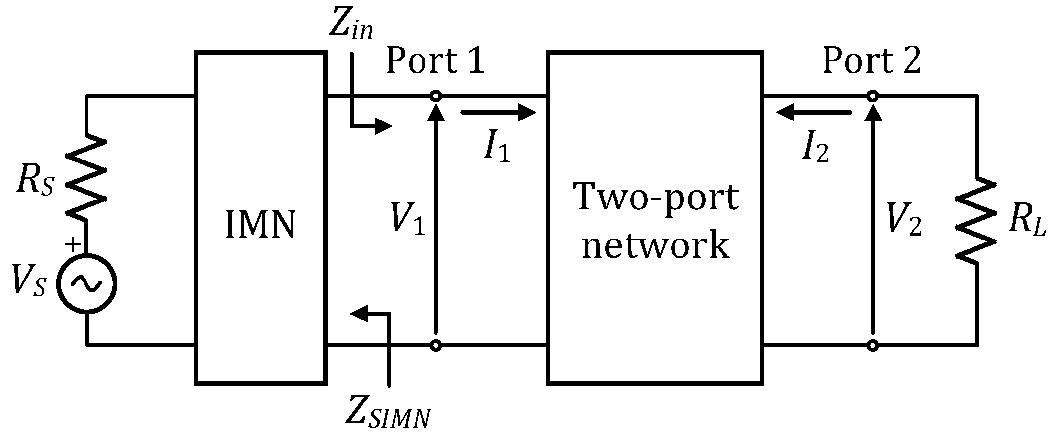
In order to achieve the maximum power transfer with the maximum available PTE of the WPT/MRC asymmetric system, it is, therefore, necessary to match the system to the power source. The common approach is to introduce an impedance matching network (IMN) between the power source and the primary side of the WPT/MRC system, as illustrated by the schematic representation in Figure 4. The matching conditions can be derived using the maximum power transfer theorem, that is, the output impedance of the matching network (with the source impedance included) has to be a complex conjugate matched to the input impedance of the WPT/MRC system, i.e., .
In general, the impedance (the source impedance seen by the two-port network) can be represented by a complex number. In order to study the PTE of the matched WPT/MRC system, it is now more appropriate to use the complex normalisation impedance associated with Port 1 in Equation (4), i.e., . Thus, the PTE of the WPT/MRC system can be calculated in a more convenient way. Anticipating that the IMN in Figure 4 will provide the matching condition of the WPT/MRC system to the power source, the PTE (defined as the ratio of the load power and available source power) in terms of S-parameters becomes:
where represents the transducer power gain [37]. Since the current analysis necessitates the use of complex reference impedance, the matrix in Equation (2) is denoted as to distinguish it from the previous matrix with real-valued reference impedances. Both matrices are, however, related to the power waves. Parameter is the element of the generalized matrix. The conversion of the matrix of the WPT/MRC asymmetric system into the generalized matrix is done according to Equation (1), where is replaced with .
The parameter can be expressed in terms of the Z-parameters as [41]:
where , while other Z-parameters in Equation (18) are previously defined in Equation (3).
Using the circuit theory, the input impedance of the WPT/MRC asymmetric system (Figure 2 and Figure 4) can be expressed as:
where:
Assuming that (the maximum power transfer theorem is adopted), and using Equations (19)–(20), the PTE of the WPT/MRC system displayed in Figure 4 can be written as:
where:
The angular frequency at which the system should be matched can be found by solving the equation:
The following analytical solution of Equation (23) is obtained:
where represents the angular frequency at which the matching condition of the WPT/MRC system with the IMN occurs. This frequency corresponds to the power source operating angular frequency.
Equation (24) can be rewritten in terms of the loaded quality factor () and resonant angular frequency () of the receiver, as follows:
where is defined in Equation (15).
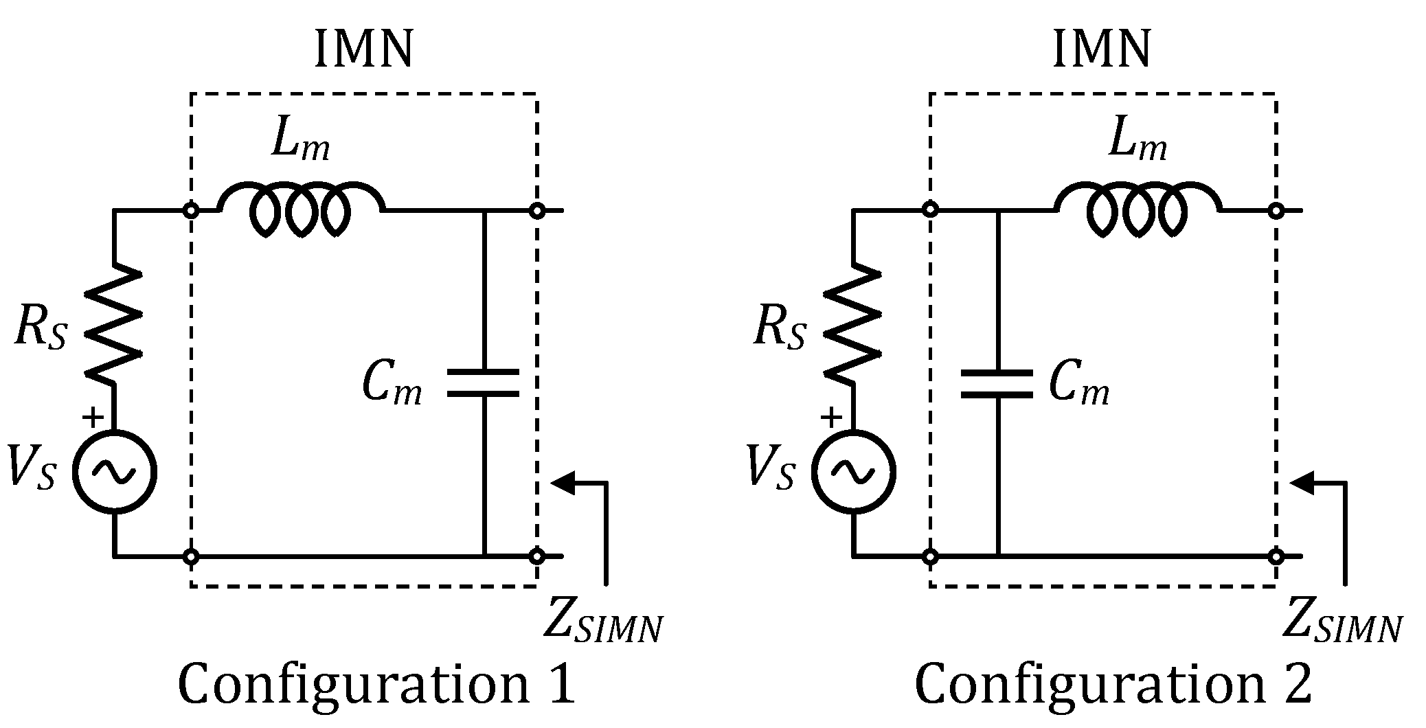
The next step is to design the IMN at the angular frequency of . The IMN is usually accomplished using a simple L-section circuit, consisting of lumped-elements, such as capacitors and inductors. Since the approach of the L-section matching circuit design is well studied in the literature, it will only be briefly discussed in terms of the L-section topology. The choice of the appropriate L-section configuration depends on the values of and the parameter (see Equation (22)). If , the matching inductance is placed in a series with the source, while the matching capacitor is placed in parallel with the primary side of the WPT/MRC system (configuration 1 in Figure 5). On the other hand, if , then the L-section topology needs to be designed by adding the matching capacitor in parallel to the source and the matching inductance is series with the primary side of the WPT/MRC system (configuration 2 in Figure 5). Calculation of the L-section matching network elements can be performed either analytically or graphically (using the Smith chart).
After the system is being matched to the power source, the power of the WPT/MRC system at Port 1 will be equal to the available source power (), given in terms of the source voltage () by:
The IMN provides no reflected power waves. Thus, the power transferred to the load is maximised. The PTE can now be calculated exactly according to Equation (17), which represents the maximum available PTE of the WPT/MRC system (maximum available transducer power gain).
3. Numerical Simulation and Experimental Results
To validate the theoretical research, the power transfer analysis of the asymmetric WPT/MRC system is investigated using numerical simulations, followed by experimental validation. The S-parameters simulations are conducted with the help of the Advanced Design System (ADS) software tool, while the analytical calculations are obtained based on the presented theoretical analysis using Matlab software. The experimental prototype of the asymmetric WPT/MRC system with the SS compensation structure is designed to verify analytical calculations.
3.1. Numerical Results
The asymmetric WPT/MRC system is designed according to the circuit model in Figure 2. The parameters of the simulated system are provided in Table 1 and are considered to be frequency-independent. It is worthwhile to mention that these parameters correspond to those of the experimental setup. The resonant frequencies of the transmitter and receiver ( and ) are 281.7 kHz and 256.9 kHz, respectively. The sweep range of the power source operating frequency () is 100–500 kHz, while the coupling coefficient varies from 0.01–0.7. The inner resistance of the power source () and the load resistance () are arbitrarily chosen to be 2.2 Ω. The equivalence of source and load resistances is irrelevant for the power transfer analysis.
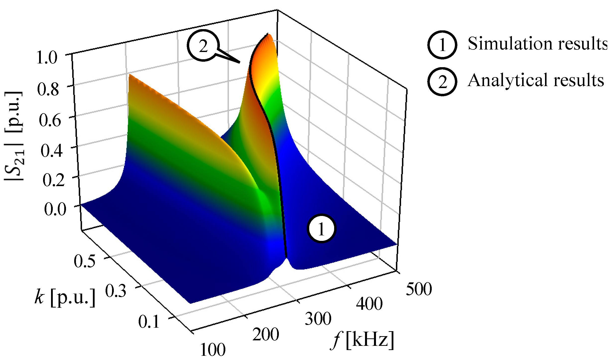
Figure 6 presents the simulation result of the magnitude of the parameter (marked as 1) with respect to the operating frequency and the coupling coefficient of the WPT/MRC system depicted in Figure 2. Results of the analytical calculation based on Equation (6), including Equations (8)–(16), are presented on the same Figure 6 with the solid black line (marked as 2).
As discussed above, the PTC and the frequency splitting phenomena can be described with the parameter. This is clearly demonstrated by the 3D surface plot in Figure 6 (marked as 1). As the result marked as 1 in Figure 6 shows, for the same values of the coupling coefficient, the magnitude of the parameter reaches not only the global maximum but also local extrema. These results fully correspond to the presented theoretical analysis. On the same 3D plot in Figure 6, the trajectory of the absolute maximum values of the magnitude of the parameter is outlined at the top of the surface (marked as 2). As can be seen, this trajectory coincides with the points in the simulation results. Moreover, the trajectory denotes the system’s operating points, which should be selected to provide higher power transferred to the load. The square magnitude of the parameter represents the normalised load power.
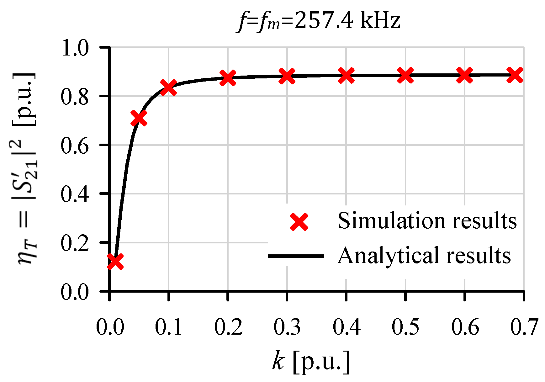
The system depicted in Figure 2 is not designed to operate at the maximum PTE, but with the maximum PTC. To achieve the maximum PTE as well, it has been suggested in the previous section to incorporate the IMN to the WPT/MRC system (schematic representation in Figure 4). Using Equation (24) and the parameters of the simulated asymmetric WPT/MRC system (Table 1), the matching frequency () of 257.4 kHz is calculated. Thereafter, the L-section matching circuit elements ( and in Figure 5) are determined for this value of the frequency and each value of the coupling coefficient in the range of 0.01–0.7. The operating frequency of the power source is tuned at the value of the previously calculated matching frequency. The PTE of the matched asymmetric WPT/MRC system versus the coupling coefficient is presented graphically in Figure 7, where red cross markers denote simulation results, while the solid black line corresponds to the calculation results of the PTE obtained by the theoretical analysis with the help of Equations (17) and (18).
It can be observed from Figure 7 that numerical and analytical results correspond with each other, thus validating the theoretical analysis. The PTE can now be expressed as the square magnitude of the parameter, whereas the power at Port 1 is equal to the available source power and it is transmitted to Port 2 with the maximum possible PTE that the system can provide. This is consistent with the theoretical investigation.
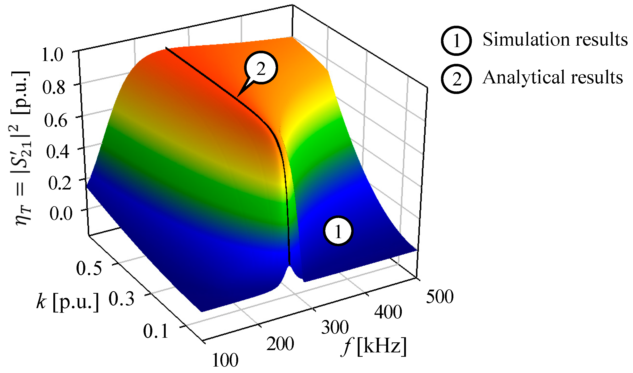
If the frequency of the power source is varied, the IMN elements have to be designed for each operating frequency and the coupling coefficient values, so as to maintain the PTE of the WPT/MRC system at a high level. Figure 8 depicts the simulated PTE of the matched system (marked as 1) with respect to the wide range of the operating frequency and the coupling coefficient. Under the assumption that the system is matched to the power source, the PTE can also be calculated according to Equations (17) and (18). Therefore, on the same plot in Figure 8, the solid black line (marked as 2) represents the trajectory of the maximum possible PTE of the system, which corresponds to the matching frequency provided by Equation (24). As can be seen, this line coincides with the points in the simulation results. Following this line, the system reaches the maximum possible transmission power and efficiency. This is in accordance with the results shown in Figure 7. On the other hand, the PTE of the matched asymmetric WPT/MRC system decreases as the operating frequency gets away from the value of the matching frequency determined by Equation (24). This is clearly observable from simulation results in Figure 8.
3.2. Experimental Results
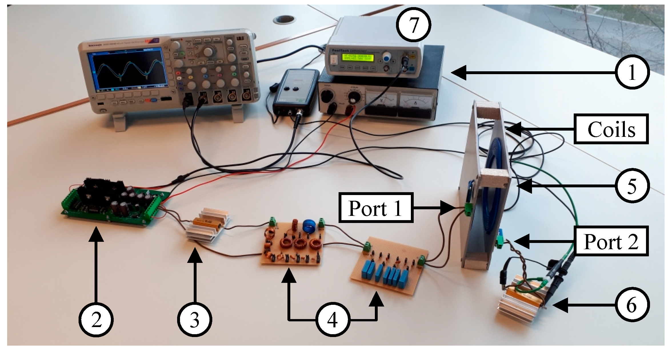
To validate the conducted power transfer analysis of the asymmetric WPT/MRC system, an experimental prototype is constructed, while the power transfer performance is evaluated by experimental tests. The prototype is displayed in Figure 9. The parameters of the prototype are consistent with those presented in Table 1.
The experimental setup, depicted in Figure 9, consists of DC power supply (marked as 1), high-frequency inverter (marked as 2), source impedance (marked as 3), IMN (marked as 4), transmitting and receiving resonators (coils with their compensation circuits, marked as 5), and load impedance (marked as 6). Transmitter and receiver air-core coils are made with a planar spiral structure with the same 100 mm inner diameter. The outer diameters of the transmitter and receiver coils are 175 mm and 155 mm, respectively. Transmitter coil has 13 turns and the receiver coil has 10 turns. Both coils are arranged in the same axis and are aligned. For the entire duration of experimental tests, the distance between coils was fixed to 35 mm, which provides the mutual inductance between them of 8.66 μH. This gives the constant coupling coefficient of 0.356. The IMN consists of capacitor and inductor arrays, which are manually configured for each operating frequency. A regulated DC power supply provides the output voltage of 10 V. The inner resistance of the power source is set to be 2.2 Ω via an external resistor, while the load impedance is also purely resistive with the resistance of 2.2 Ω. As previously mentioned, the equivalence of source and load resistances is irrelevant for the power transfer analysis. The high-frequency inverter is used to drive the WPT/MRC system and is controlled via a square wave signal generated by the function generator (marked as 7 in Figure 9). All of the above-mentioned electrical parameters of the system were measured by the impedance analyser at the frequency of 250 kHz.
During the experiment, input and output voltage and current of the resonators are measured with an oscilloscope. Due to the high bandwidth, the Rogowski probe is used for the current measurement, while the oscilloscope voltage probe is used for the voltage measurement. Thus, the input and output instantaneous power of the WPT/MRC system are obtained as the product of the corresponding instantaneous values of voltage and current. The active power is determined as the average value of the calculated instantaneous power, so the PTE of the WPT/MRC system can be readily calculated.
The S-parameters measurement of the WPT/MRC system is performed in a 50 Ω impedance system with the Bode 100 Omicron Lab VNA. However, in this paper, the reference impedances used for the normalisation process are not equal to the normalisation impedance of 50 Ω. Moreover, in the previous section it has been explained that the generalized matrix is defined using the complex reference impedance. Therefore, the measured S-parameters in a 50 Ω impedance system have to be renormalized. An exact renormalization procedure is provided in Appendix B.
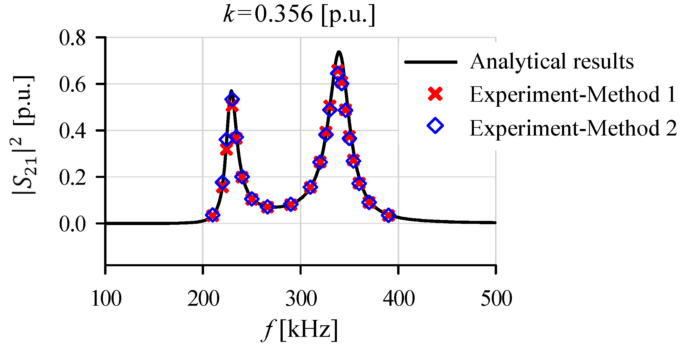
In the first experiment, the asymmetric WPT/MRC system from Figure 9 was operated without the IMN. To explore the PTC of the system, the load power was measured over the operating frequency range of 210–390 kHz and then was scaled by the available source power, thus leading to the normalised load power. The results of the experiment are depicted with red cross markers in Figure 10 (Method 1). Likewise, the PTC of the WPT/MRC system was investigated through the measurement of the parameter. The results of the square magnitude of the renormalized parameter are also presented in Figure 10 (Method 2), denoted with blue diamond markers.
As is to be expected, the results of the previous two experimental tests are almost identical. This indicates that the PTC analysis of the WPT/MRC system can completely rely on the S-parameters concept, which is of great practical importance. This fact is based not only on the experimental results, but also on the presented theoretical investigation. On the same plot in Figure 10, the analytical calculation of the square magnitude of the parameter, with respect to the operating frequency, is depicted with a solid black line. As can be seen, the theoretical results are in excellent agreement with the experimental results.
In the next experiment, the PTE of the matched asymmetric WPT/MRC system was evaluated to compare theoretical and experimental results. The WPT/MRC system was connected to the power source via the tuneable IMN, so as to ensure the maximum PTE. The input power of the WPT/MRC system (power at Port 1 in Figure 9) and the load power were measured over the operating frequency range of 220–290 kHz, in a step of 10 kHz. The results of the PTE are shown in Figure 11 with red cross markers (Method 1). It can be observed that, for the constant value of the coupling coefficient, the PTE varies with the operating frequency, resulting in the maximum of around 0.87 at the frequency of about 250 kHz. This is in accordance with the previous numerical calculations (Figure 7). Since the WPT/MRC system was matched to the power source, the PTE can be observed with the generalized S-parameters. After measuring the parameter and its renormalization to the desired reference impedance, the PTE of the system can be expressed as the square magnitude of the parameter. The results of the PTE are depicted in Figure 11 with blue diamond markers (Method 2). It can be noticed that both experimentally obtained results of the PTE (Method 1 and Method 2) are in a very good agreement. This proves the effectiveness of the S-parameters concept analysis of the PTE. For comparison purposes, the results of the analytical calculation are also presented in Figure 11 (solid black line). The analytical results are in quite good correlation with the experimental ones (Figure 11). The slight difference between them exists at higher operating frequencies. This is caused by variations of the overall WPT/MRC system parameters due to frequency effect. Notwithstanding, both experimental and theoretical results are basically consistent with each other. Finally, this confirms that the power transfer analysis of the matched asymmetric WPT/MRC system can be properly performed using the generalized S-parameters.
4. Conclusions
WPT technique based on the MRC is identified as a key technology for various commercial applications. However, this concept faces many issues. The main concern about WPT/MRC systems is power efficiency. It lays at the root of most of the WPT/MRC system design challenges. Therefore, a deep analysis of PTC and PTE is essential.
In this paper, the power transfer of the two-coil asymmetric wireless transmission system was considered in details based on the S-parameters. It was shown that the proposed methodology is quite adequate for the performance characterisation of the WPT/MRC system, since it entirely provides information on the power transfer capacity via the S-parameters, including frequency splitting phenomena. Unlike other methods used to characterise power transfer properties of the transmission system, the proposed method is highly favourable as the S-parameters are simply obtained with the VNA. With the use of the S-parameters based on the power waves, the analytical model of the SS compensated WPT/MRC asymmetric system was used to define the operating frequency of the system to provide higher power transferred to the load, therefore increasing the PTC. The analysis was further extended on the system with the incorporated IMN. These yield zero reflected power at the network input, making the WPT/MRC system operate at the maximum possible PTE, with the maximal power transferred to the load at the same time. Although the efficiency of the matched WPT/MRC asymmetric system varies with the operating frequency, the paper demonstrated that the PTE can still be observed with the generalized S-parameters. The validity of all presented theoretical analyses was successfully proven by numerical simulations, as well as experimentally.
The proposed theoretical investigation concept on the power transfer performance is applicable not only for the asymmetric WPT/MRC system with the SS compensation circuit but also for other WPT/MRC structures with different compensation topologies.
Author Contributions
Conceptualization, Ž.D.; methodology, Ž.D., D.R. and V.V.; software, Ž.D.; validation, Ž.D. and D.R.; formal analysis, Ž.D.; investigation, Ž.D. and D.R.; resources, D.O.; writing—original draft preparation, Ž.D. and D.R; writing—review and editing, V.V. and D.O.; visualization, D.R.; supervision, V.V. All authors have read and agreed to the published version of the manuscript.
Funding
This research has been supported by the Ministry of Education, Science and Technological Development of the Republic of Serbia through the project No. 451-03-9/2021-14/200156: “Innovative scientific and artistic research from the FTS activity domain”.
Conflicts of Interest
The authors declare no conflict of interest.
Appendix A
Coefficients in Equation (8) can be expressed in terms of inductances, capacitances, and resistances of the WPT/MRC system components, including the inner resistance of the power source and the load resistance, and have the following forms:
where:
The general solutions of Equation (8) are:
where:
Appendix B
The S-parameters are measured in a 50 Ω impedance system. Their renormalization to S-parameters for an arbitrary reference impedance can be performed by using:
where: represents matrix in the new reference impedance system, represents matrix in the 50 Ω impedance system, is the identity matrix, and and are the original (50 Ω) and new reference impedance, respectively. Symbol * denotes a complex conjugate. The matrix is given by:
References
- Tesla, N. Apparatus for Transmitting Electrical Energy. Patent 1,119,732, 1 December 1914. [Google Scholar]
- Kurs, A.; Karalis, A.; Moffatt, R.; Joannopoulos, J.D.; Fisher, P.; Soljačic, M. Wireless Power Transfer via Strongly Coupled Magnetic Resonances. Science 2007, 317, 83–86. [Google Scholar] [CrossRef] [Green Version]
- Houran, M.A.; Yang, X.; Chen, W. Magnetically Coupled Resonance WPT: Review of Compensation Topologies, Resonator Structures with Misalignment, and EMI Diagnostics. Electronics 2018, 7, 296. [Google Scholar] [CrossRef] [Green Version]
- Aditya, K.; Williamson, S.S. Design Guidelines to Avoid Bifurcation in a Series–Series Compensated Inductive Power Transfer System. IEEE Trans. Ind. Electron. 2019, 66, 3973–3982. [Google Scholar] [CrossRef]
- Wagih, M.; Komolafe, A.; Zaghari, B. Dual-Receiver Wearable 6.78 MHz Resonant Inductive Wireless Power Transfer Glove Using Embroidered Textile Coils. IEEE Access 2020, 8, 24630–24642. [Google Scholar] [CrossRef]
- Na, K.; Kim, J.; Park, Y.-J. Free-Positioning Magnetic Resonance Wireless Power Transfer System for Biomedical Devices. In Proceedings of the 2019 IEEE Wireless Power Transfer Conference (WPTC), London, UK, 18–21 June 2019; pp. 497–501. [Google Scholar]
- Gati, E.; Kokosis, S.; Patsourakis, N.; Manias, S. Comparison of Series Compensation Topologies for Inductive Chargers of Biomedical Implantable Devices. Electronics 2019, 9, 8. [Google Scholar] [CrossRef] [Green Version]
- Varikkottil, S.; L, F.D.J. Estimation of Optimal Operating Frequency for Wireless EV Charging System under Misalignment. Electronics 2019, 8, 342. [Google Scholar] [CrossRef] [Green Version]
- Despotovic, Z.; Vasic, V.; Oros, D.; Jerkan, D. Coupling Factor Estimation in Vehicle-to-Vehicle Wireless Power Transfer System Based on Geometry Properties. In Proceedings of the 2020 IEEE Wireless Power Transfer Conference (WPTC), Seoul, Korea, 15–19 November 2020; pp. 227–230. [Google Scholar]
- Sample, A.P.; Meyer, D.T.; Smith, J.R. Analysis, Experimental Results, and Range Adaptation of Magnetically Coupled Resonators for Wireless Power Transfer. IEEE Trans. Ind. Electron. 2011, 58, 544–554. [Google Scholar] [CrossRef]
- Huang, R.; Zhang, B.; Qiu, D.; Zhang, Y. Frequency Splitting Phenomena of Magnetic Resonant Coupling Wireless Power Transfer. IEEE Trans. Magn. 2014, 50, 1–4. [Google Scholar] [CrossRef]
- Nguyen, H.; Agbinya, J.I. Splitting Frequency Diversity in Wireless Power Transmission. IEEE Trans. Power Electron. 2015, 30, 6088–6096. [Google Scholar] [CrossRef]
- Niu, W.; Gu, W.; Chu, J. Analysis and experimental results of frequency splitting of underwater wireless power transfer. J. Eng. 2017, 2017, 385–390. [Google Scholar] [CrossRef]
- Zhang, Y.; Zhao, Z. Frequency Splitting Analysis of Two-Coil Resonant Wireless Power Transfer. IEEE Antennas Wirel. Propag. Lett. 2014, 13, 400–402. [Google Scholar] [CrossRef]
- Zhang, Y.; Zhao, Z.; Chen, K. Frequency-Splitting Analysis of Four-Coil Resonant Wireless Power Transfer. IEEE Trans. Ind. Appl. 2013, 50, 2436–2445. [Google Scholar] [CrossRef]
- Kim, J.-G.; Wei, G.; Kim, M.-H.; Ryo, H.-S.; Ri, P.-C.; Zhu, C. A Splitting Frequencies-Based Wireless Power and Information Simultaneous Transfer Method. IEEE Trans. Circuits Syst. I Regul. Pap. 2018, 65, 4434–4445. [Google Scholar] [CrossRef]
- Chen, L.; Liu, S.; Zhou, Y.C.; Cui, T.J. An Optimizable Circuit Structure for High-Efficiency Wireless Power Transfer. IEEE Trans. Ind. Electron. 2013, 60, 339–349. [Google Scholar] [CrossRef]
- Wang, S.; Hu, Z.; Rong, C.; Lu, C.; Tao, X.; Chen, J.; Liu, M. Optimisation analysis of coil configuration and circuit model for asymmetric wireless power transfer system. IET Microwaves Antennas Propag. 2018, 12, 1132–1139. [Google Scholar] [CrossRef]
- Lyu, Y.-L.; Meng, F.-Y.; Yang, G.-H.; Che, B.-J.; Wu, Q.; Sun, L.; Erni, D.; Li, J.L.-W. A Method of Using Nonidentical Resonant Coils for Frequency Splitting Elimination in Wireless Power Transfer. IEEE Trans. Power Electron. 2015, 30, 6097–6107. [Google Scholar] [CrossRef]
- Zhang, Z.; Zhang, B. Omnidirectional and Efficient Wireless Power Transfer System for Logistic Robots. IEEE Access 2020, 8, 13683–13693. [Google Scholar] [CrossRef]
- Zhou, J.; Zhang, B.; Xiao, W.; Qiu, D.; Chen, Y. Nonlinear Parity-Time-Symmetric Model for Constant Efficiency Wireless Power Transfer: Application to a Drone-in-Flight Wireless Charging Platform. IEEE Trans. Ind. Electron. 2018, 66, 4097–4107. [Google Scholar] [CrossRef]
- Narayanamoorthi, R.; Juliet, A.V.; Chokkalingam, B. Frequency Splitting-Based Wireless Power Transfer and Simultaneous Propulsion Generation to Multiple Micro-Robots. IEEE Sens. J. 2018, 18, 5566–5575. [Google Scholar] [CrossRef]
- Bao, K.; Zekios, C.L.; Georgakopoulos, S.V. A Wearable WPT System on Flexible Substrates. IEEE Antennas Wirel. Propag. Lett. 2019, 18, 931–935. [Google Scholar] [CrossRef]
- Lee, H.H.; Kang, S.H.; Jung, C.W. MR-WPT With Reconfigurable Resonator and Ground for Laptop Application. IEEE Microw. Wirel. Components Lett. 2018, 28, 269–271. [Google Scholar] [CrossRef]
- Zhu, Q.; Zhang, Y.; Liao, C.; Guo, Y.; Wang, L.; Li, F. Experimental Study on Asymmetric Wireless Power Transfer System for Electric Vehicle Considering Ferrous Chassis. IEEE Trans. Transp. Electrification 2017, 3, 427–433. [Google Scholar] [CrossRef]
- Moon, S.; Moon, G.-W. Wireless Power Transfer System with an Asymmetric 4-Coil Resonator for Electric Vehicle Battery Chargers. IEEE Trans. Power Electron. 2015, 31, 1. [Google Scholar] [CrossRef]
- Li, Y.; Ni, X.; Liu, J.; Wang, R.; Ma, J.; Zhai, Y.; Huang, Y. Design and Optimization of Coupling Coils for Bidirectional Wireless Charging System of Unmanned Aerial Vehicle. Electronics 2020, 9, 1964. [Google Scholar] [CrossRef]
- Guan, Z.; Zhang, B.; Qiu, D. Influence of Asymmetric Coil Parameters on the Output Power Characteristics of Wireless Power Transfer Systems and Their Applications. Energies 2019, 12, 1212. [Google Scholar] [CrossRef] [Green Version]
- Kim, J.; Kim, D.-H.; Park, Y.-J. Free-Positioning Wireless Power Transfer to Multiple Devices Using a Planar Transmitting Coil and Switchable Impedance Matching Networks. IEEE Trans. Microw. Theory Tech. 2016, 64, 3714–3722. [Google Scholar] [CrossRef]
- Mou, X.; Gladwin, D.T.; Zhao, R.; Sun, H. Survey on magnetic resonant coupling wireless power transfer technology for electric vehicle charging. IET Power Electron. 2019, 12, 3005–3020. [Google Scholar] [CrossRef] [Green Version]
- Beh, T.C.; Kato, M.; Imura, T.; Oh, S.; Hori, Y. Automated Impedance Matching System for Robust Wireless Power Transfer via Magnetic Resonance Coupling. IEEE Trans. Ind. Electron. 2012, 60, 3689–3698. [Google Scholar] [CrossRef]
- Rotaru, M.D.; Tanzania, R.; Ayoob, R.; Kheng, T.Y.; Sykulski, J.K. Numerical and experimental study of the effects of load and distance variation on wireless power transfer systems using magnetically coupled resonators. IET Sci. Meas. Technol. 2015, 9, 160–171. [Google Scholar] [CrossRef] [Green Version]
- Seo, D.-W. Comparative Analysis of Two- and Three-Coil WPT Systems Based on Transmission Efficiency. IEEE Access 2019, 7, 151962–151970. [Google Scholar] [CrossRef]
- Tao, X.; Rong, C.; Lu, C.; Huang, X.; Zeng, Y.; Hu, Z.; Liu, M. A Novel Approach to Reach Impedance Matching in Wireless Power Transfer Systems. Appl. Sci. 2019, 9, 976. [Google Scholar] [CrossRef] [Green Version]
- Kurokawa, K. Power Waves and the Scattering Matrix. IEEE Trans. Microw. Theory Tech. 1965, 13, 194–202. [Google Scholar] [CrossRef] [Green Version]
- Penfield, P. Noise in Negative-Resistance Amplifiers. IRE Trans. Circuit Theory 1960, 7, 166–170. [Google Scholar] [CrossRef]
- Rahola, J. Power Waves and Conjugate Matching. IEEE Trans. Circuits Syst. II Express Briefs 2008, 55, 92–96. [Google Scholar] [CrossRef]
- Collin, R.E. Foundations for Microwave Engineering; Institute of Electrical and Electronics Engineers (IEEE): New York, NY, USA, 2001; pp. 268–276. [Google Scholar]
- Kulkarni, R.G. A New Method for Solving Quartics. Int. J. Math. Sci. Educ. 2009, 2, 24–26. [Google Scholar]
- Cartwright, K. V Correction to A new method for solving quartics. Int. J. Math. Sci. Educ. 2011, 4, 30–31. [Google Scholar]
- Frickey, D. Conversions between S, Z, Y, H, ABCD, and T parameters which are valid for complex source and load impedances. IEEE Trans. Microw. Theory Tech. 1994, 42, 205–211. [Google Scholar] [CrossRef]
Figure 1.
The magnetically coupled resonant wireless power transmission (WPT/MRC) system classification. Series-series (SS), series-parallel (SP), parallel-series (PS), and parallel-parallel (PP) compensated structures.
Figure 1.
The magnetically coupled resonant wireless power transmission (WPT/MRC) system classification. Series-series (SS), series-parallel (SP), parallel-series (PS), and parallel-parallel (PP) compensated structures.

Figure 2.
The equivalent circuit model of the magnetically coupled resonant wireless power transmission asymmetric system with the series-series compensation structure.
Figure 2.
The equivalent circuit model of the magnetically coupled resonant wireless power transmission asymmetric system with the series-series compensation structure.

Figure 3.
The magnetically coupled resonant wireless power transmission system represented as a two-port passive linear network model with the S-parameters.
Figure 3.
The magnetically coupled resonant wireless power transmission system represented as a two-port passive linear network model with the S-parameters.

Figure 4.
The magnetically coupled resonant wireless power transmission system with the impedance matching network (IMN), represented as a two-port passive linear network model with the generalised S-parameters.
Figure 4.
The magnetically coupled resonant wireless power transmission system with the impedance matching network (IMN), represented as a two-port passive linear network model with the generalised S-parameters.

Figure 5.
L-section matching network configuration.

Figure 6.
The magnitude of the scattering parameter S21 (1) and the trajectory of its maximum values (2) expressed in terms of the operating frequency (f) and coupling coefficient (k).
Figure 6.
The magnitude of the scattering parameter S21 (1) and the trajectory of its maximum values (2) expressed in terms of the operating frequency (f) and coupling coefficient (k).

Figure 7.
Power transfer efficiency of the matched asymmetric wireless power transmission system versus the coupling coefficient (k).
Figure 7.
Power transfer efficiency of the matched asymmetric wireless power transmission system versus the coupling coefficient (k).

Figure 8.
Power transfer efficiency of the matched asymmetric wireless power transmission system (1) and the trajectory of its maximum values (2) expressed in terms of the operating frequency (f) and coupling coefficient (k).
Figure 8.
Power transfer efficiency of the matched asymmetric wireless power transmission system (1) and the trajectory of its maximum values (2) expressed in terms of the operating frequency (f) and coupling coefficient (k).

Figure 9.
Experimental setup of the two-coil asymmetric wireless power transmission system (1–DC power supply, 2–high-frequency inverter, 3–source impedance, 4–impedance matching network, 5–transmitting and receiving coils, 6–load impedance).
Figure 9.
Experimental setup of the two-coil asymmetric wireless power transmission system (1–DC power supply, 2–high-frequency inverter, 3–source impedance, 4–impedance matching network, 5–transmitting and receiving coils, 6–load impedance).

Figure 10.
Normalised load power of the asymmetric wireless power transmission system versus operating frequency (f).
Figure 10.
Normalised load power of the asymmetric wireless power transmission system versus operating frequency (f).

Figure 11.
Power transfer efficiency of the matched asymmetric wireless power transmission system versus operating frequency (f).
Figure 11.
Power transfer efficiency of the matched asymmetric wireless power transmission system versus operating frequency (f).


Table 1.
Parameters of the magnetically coupled resonant wireless power transmission system.
| Component | Parameter | Value |
|---|---|---|
| Transmitter coil inductance | 31.3 µH | |
| Receiver coil inductance | 18.9 µH | |
| Transmitter coil resistance | 0.316 Ω | |
| Receiver coil resistance | 0.237 Ω | |
| Transmitter compensation capacitor | 10.2 nF | |
| Receiver compensation capacitor | 20.3 nF | |
| Transmitter compensation capacitor resistance | 0.044 Ω | |
| Receiver compensation capacitor resistance | 0.022 Ω |
Publisher’s Note: MDPI stays neutral with regard to jurisdictional claims in published maps and institutional affiliations. |
© 2021 by the authors. Licensee MDPI, Basel, Switzerland. This article is an open access article distributed under the terms and conditions of the Creative Commons Attribution (CC BY) license (https://creativecommons.org/licenses/by/4.0/).
Share and Cite
MDPI and ACS Style
Despotović, Ž.; Reljić, D.; Vasić, V.; Oros, D. Power Transfer Analysis of an Asymmetric Wireless Transmission System Using the Scattering Parameters. Electronics 2021, 10, 906. https://doi.org/10.3390/electronics10080906
AMA Style
Despotović Ž, Reljić D, Vasić V, Oros D. Power Transfer Analysis of an Asymmetric Wireless Transmission System Using the Scattering Parameters. Electronics. 2021; 10(8):906. https://doi.org/10.3390/electronics10080906
Chicago/Turabian StyleDespotović, Živadin, Dejan Reljić, Veran Vasić, and Djura Oros. 2021. "Power Transfer Analysis of an Asymmetric Wireless Transmission System Using the Scattering Parameters" Electronics 10, no. 8: 906. https://doi.org/10.3390/electronics10080906
Note that from the first issue of 2016, this journal uses article numbers instead of page numbers. See further details here.