Article

Numerical 3D Finite Element Assessment of Bending Moment-Resisting Frame Equipped with Semi-Disconnected Steel Plate Shear Wall and Yielding Plate Connection

by
Seyed Morteza Salimi
1,
Sepideh Rahimi
1,*,
Mohamad Hoseinzadeh
1,
Denise-Penelope N. Kontoni
2,3,* and
Mehdi Ebadi-Jamkhaneh
4,*
1
Department of Civil Engineering, Nour Branch Islamic Azad University, Nour 46418-59558, Iran
2
Department of Civil Engineering, University of the Peloponnese, GR-26334 Patras, Greece
3
School of Science and Technology, Hellenic Open University, GR-26335 Patras, Greece
4
Department of Civil Engineering, School of Engineering, Damghan University, Damghan 36716-41167, Iran
*
Authors to whom correspondence should be addressed.
Metals 2021, 11(4), 604; https://doi.org/10.3390/met11040604
Submission received: 26 February 2021 / Revised: 25 March 2021 / Accepted: 4 April 2021 / Published: 8 April 2021
(This article belongs to the Special Issue Sustainable and Resilient Steel Structures)

Abstract

:
Steel plate shear walls (SPSWs) have advantages such as high elastic stiffness, stable hysteresis behavior, high energy absorption capacity, and decent ductility. However, one of the main drawbacks of SPSWs is their buckling under lateral loading. To address this issue, a simple and practical solution in the form of using a trapezoidal plate moment connection (PMC) and a narrow gap between the infill plate and columns is presented. The PMC will act as an energy absorber, similar to a yielding steel plate, and keep the other structural members in an elastic state. Extensive three-dimensional finite element (FE) models of the SPSW system were investigated under monotonic and cyclic loading. The results revealed that by separating the infill plate from the vertical boundary elements and using two vertical edge stiffeners at both edges of the wall, the same lateral bearing capacity of the conventional system can be achieved. In addition, by increasing the thickness of the PMC from 6.5 to 26 mm, the load-bearing capacity, energy dissipation, and elastic stiffness increased approximately 2, 2.5, and 3.2 times, respectively. It was also found that the flexural capacity ratio of the connection to the beam had little effect on the overall force–displacement behavior. However, it can affect the system failure mechanism. Finally, the tension field inclination angle for such SPSWs was proposed in the range of 30 to 35°.

1. Introduction

Steel plate shear wall (SPSW) systems are one of the fastest-developing lateral resisting systems utilised in medium to high-rise buildings. To investigate the performance of SPSW, several analytical models were created. Basler and Thürlimann [1] suggested plate girder design, which was further used as the basis for more SPSW analytical models. Early studies on SPSW post-buckling strength were carried out at the University of Alberta, and therefore, the strip model was presented as a basis to calculate SPSWs’ post-buckling strength. These studies inspired further studies on unstiffened SPSWs. This model became the basis for design regulations for a variety of guidelines such as AISC341-05 [2], CAN/CSA S16-1 [3], and FEMA 450 [4]. Extensive experimental, analytical, and numerical studies have been conducted during the recent decades on unstiffened thin SPSWs as the main focus of the present study. Wagner [5] conducted the first major research on plate girders’ post-buckling behavior and used certain tests to suggest diagonal tension field theory. Some of the experimental studies conducted on thin steel shear walls include Timler and Kulak [6], Driver [7], Lubell [8], and Vian et al. [9]. The results of these studies showed that the useful post-buckling resistance, high stiffness, strength, and ductility, sustainable hysteresis features, and high plastic energy absorbability of SPSWs can tolerate lateral loads. According to the proper post-buckling strength of a high-strength steel infill plate, the thickness of the infill wall can be reduced in tall buildings. Purba and Bruneau [10] studied unreinforced thin infill wall behavior considering a regular opening model. First of all, a series of shear walls without/with opening were tested. They considered a rigid diaphragm and rigid beam on boundary conditions of the wall. Eventually, they presented a shear strength of the infill wall depending on the shear strength of the solid panel, the diameter of the opening, and the distance between openings. An experimental study on stiffened and unstiffened shear wall behavior has been conducted by Sabouri-Ghomi and Sajjadi [11]. Their results showed that stiffener increased the energy absorption and shear strength of the steel wall. Hosseinzadeh and Tehranizadeh [12] studied the general behavior of SPSWs in dual systems, including the role of steel plate tension field and frame boundary conditions. The results demonstrated that the presence of an infill wall has significant importance for the improvement of moment-resisting frame system performance, especially for multi-story frames, in terms of strength, stiffness, ductility, and energy dissipation capacity. Machaly et al. [13] conducted a numerical study on the ultimate shear strength of SPSW. Integrated parametric analysis to assess the effect of geometrical parameters and wall materials in its ultimate shear strength has been conducted. Du et al. [14] investigated the seismic performance and proposed a two-story thin steel shear wall equipped with horizontal and vertical stiffeners. Results indicated that the structure was maintained at the life safety performance level through a strengthening approach.
To resist lateral loading, one of the main steel lateral load-bearing systems is the SPSW system. The main members of a steel shear wall include a steel plate of walls, beams, and boundary columns. On the other hand, if required, a horizontal or vertical stiffener is used to increase the rigidity and out-of-plane buckling resistance of the wall. This strengthening method was used to prevent the premature buckling of steel infill plates [15]. Due to the high post-buckling capacity of a thin infill plate caused by the wall plate diagonal tension field, thin stiffened SPSWs are favorable. Significant stiffness and shear strength, sustainable hysteresis behavior, high energy dissipation, and high ductility, as well as a high degree of indeterminacy of steel shear wall, caused this system to be permanently considered as one of the main design alternatives for structures exposed to severe seismic and wind loadings [16]. In some countries such as Japan and China, using a stiffener is desirable to ensure high energy absorbability and ductility without using thick plates. However, using a stiffener may be a little critical and improper, which is related to using a high labor force for the installation process [17] and increasing construction costs. On the other hand, SPSWs without stiffeners are more popular in Northern America, due to the cost-effectiveness and decent performance of unstiffened plates. Unstiffened SPSW system includes steel infill plates, confined by horizontal boundary elements (HBE) (beam) and vertical boundary elements (VBE) (column).
From amongst unstiffened SPSWs, defects in American Institute of Steel Construction (AISC) standards [18,19] may be seen concerning the fact that infill plate post-buckling tension field generates big lateral forces in VBE, which in turn develops major bending moment and excessive axial forces in columns. Therefore, big cross-section columns shall always be used to provide proper stiffness and strength. This is a big defect, influencing implementation cost. On the other hand, in this system, the SPSW is connected with boundary columns and beams using fillet welding. High vertical fillet welds result in an increase in cost and serious problems of burned steel plate during overhead welding [20]. The other point that may be mentioned is that column design depends on selecting a wall plate. A thicker steel wall plate and high strength materials result in a heavier column. Analyses and tests conducted on unstiffened SPSWs [21,22] showed that these walls may be buckled along diagonal compressive regions for a small drift ratio of 0.005 radians. Most of the studies conducted on unstiffened SPSWs were focused on improving post-buckling performance, ductility, and energy absorption. In these studies, infill wall elastic buckling, which often occurs under small shear forces, was less considered. Elastic buckling of thin steel plates resulted in the limitation of the SPSWs’ application. This phenomenon caused a reduction in initial stiffness and a small yielding drift ratio [23,24]. Although there are limited cases where service-level performance is focused on considering performance-based design philosophy [23], AISC determines regulations without deformation and drift ratio requirements under service conditions. Using beam to column welded joints in this system often results in an unwanted failure of panel zone, and doubler plates shall be used in the column web at the panel zone, which in turn increases operational costs. Using current welded moment connections, in which beam flange is connected vertically to column web, requires a continuity plate at the column web. This results in an increase in cost and stiffness in implementation. The last defect of these columns is that the current seismic design guideline considers weak beam–strong column philosophy as one of the design requirements of boundary elements, which in turn results in an increase in column sizes beyond the system demands.
From amongst design issues and subjects for SPSWs completely connected to boundary elements, three cases are important: (1) tension field region, resulting in big, heavy, and expensive columns; (2) joints with complete penetrative weld in common systems, which are not cost-effective and need on-site welding and ultrasonic tests; and (3) thin steel walls against lateral loads (such as wind and earthquake) that are prone to buckling. Therefore, the infill wall in this study has targeted previously addressed problems considering two key issues. These two key issues included steel wall separation ability from boundary elements and replacing full penetrative weld with a PMC. The overarching aim of this study is to develop an SPSW system that can address the issues and drawbacks of the current SPSW system. All numerical studies were conducted to achieve both the desired ductile behavior and a reduction in fabrication costs. Considering extensive studies conducted on examining SPSWs’ performance exposed to different loads, the number of studies on examining thin SPSW using PMC and a narrow gap between infill wall and the column is limited. Therefore, in this study, an effective approach of high-performance and a more cost-effective SPSW together with a proper connection are investigated by the three-dimensional (3D) finite element (FE) ABAQUS software (Dassault Systemes Simulia Corporation, Providence, RI, USA) [25].

2. Materials and Methods

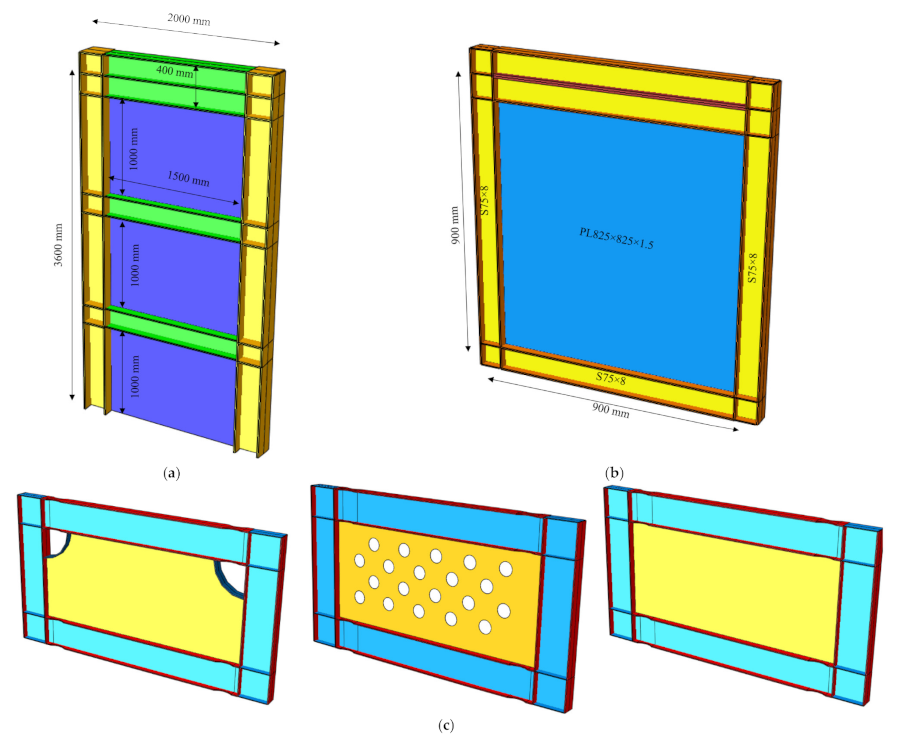
2.1. Introducing the Connection

There are several drawbacks associated with using conventional bending moment connection, such as costly complete penetrative welding and time consumption. On the other hand, to satisfy the requirements of moment connections, the “strong column–weak beam” philosophy shall be used, which results in a big size and heavy column. To remove the mentioned disadvantages and defects in common moment connections, a new type of moment connection with a plate is suggested, which has flexural behavior similar to the current connection and may be a good alternative for them.
In Figure 1, a new yielding PMC has been shown, which may be used in bolted and welded types. For the welded option, the connection plate is welded to the column flange and the beam at the factory and the project site, respectively. The welded type may be of fillet or groove welds. For some heavy and big beams, these welds are suggested for a complete penetration weld.
A T-shape plate is suggested, which shall be welded to the beam at the factory, and the plate is bolted to the column flange at the project site. Both bolted and welded joints have five distinctive components: (1) connection plate; (2) beam; (3) column; (4) column to connection plate; and (5) beam to connection plate. These elements are explained as per the following:
A: Connection plate: The plate is in the form of a vertical plate and on-beam web and column plate. Mainly, it is exposed to shear forces and bending moments and a little axial force. The formation of a plastic hinge occurs first due to in-plane yielding. The panel zone is designed for a yield of the region between the face of the column flange and beam ends. The only inelastic region of the connection is the area between the face of the column flange and beam endings. The plate is the only element of the connection that is yielded and absorbs energy and acts as a fuse and prevents other elements from entering into the inelastic region.
This plate has sufficient flexural capacity to encounter the bending moments caused by different loading combinations mentioned in the guidelines. The plate’s plastic hinge region shall be designed in a way to have sufficient ductility and meet the required joint rotation. On the other hand, the plate shall be designed in a way to have enough rotational stiffness to keep the floors drifts within the permitted threshold. The main parameters in designing joint plates include depth and thickness, the free distance between beam ending and column surface, and panel zone materials. The effect of these parameters on strength, stiffness, and ductility shall be considered.
B: Beam: By using the connection plate in this joint as a fuse, it is expected that the beam behaves at the elastic region due to lateral loading, which is one of the main advantages of this joint. In this joint, the beam shall be designed in a way to meet strength requirements against weight loads and lateral load stiffness.
C: Column: Due to using a connection plate as a fuse and its position in the vicinity to the column face, it is expected that the column remains in the elastic region (merely through limiting column web yielding). Regarding such a case, a column is exposed to a plastic moment. The small plastic moment capacity of the connection plate in comparison to the beam (approximately 60–80% of beam plastic capacity) results in yielding of the column web and a decreased need for doubler plates for most cases. On the other hand, no direct connection is developed by beam web to column web. Therefore, it causes a decrease in stress concentration, deformation, and changes in the shape of column webs or local yielding column web, local buckling of column web, and detachment of web. On the other hand, the continuity plate is rarely needed for this system. Therefore, there is no need to observe a “weak beam–strong column” criterion in this system [26,27].
In addition to the new plate moment connection, other traditional and well-established steel connections such as shear and semi-rigid connections can also be used in the proposed shear wall system without affecting the benefits due to the separation of the infill wall from the boundary column. As a result of the elimination of the need to connect the infill plate to both beams and columns, this can be a good option for use in the structural system. The infill plate modules are connected to the beams through fish plates that have been welded to the beams in the factory. After transferring to the site, the infill plate was connected to the fish plate by high strength bolts and welded directly to the PMC.

2.2. Finite Elements Modeling and Validation

In this part, different parts of numerical modeling are presented together with validation models and applying the boundary conditions, loading, and their details. After comparing and examining numerical models with experimental results, a numerical model, including a thin SPSW with a PMC, will be investigated. Therefore, validation shall be made in two parts. The first part of validation is related to the model with a connection plate, which prevents direct interaction between the beam and column, and the second part of validation is about the performance of various types of SPSWs.

2.2.1. First Part of Validation

An experimental model made by Guo et al. [28] is used for joint plate numerical model validation. They tested six experimental specimens from beam to column moment connection with changes to different parameters such as the ending plate thickness, the existence of a stiffener for the ending plate, and the column web stiffener, which was exposed to cyclic loading. In Figure 2, the geometrical details of the connection had been given.
The S-3 model [28] was selected for numerical validation. In this model, both stiffeners for the ending plate and column web were available. Eight high-strength bolts (yield stress is 960 MPa and final yield stress is 1040 MPa) were used for the ending plate to column joint. Whereas it had been mentioned in a report presented by authors that no slipping and yielding had occurred in the bolts. Therefore, in numerical modeling, the bolts modeling had been ignored due to increasing analysis time and contact property between different parts. The “tie” option had been used for connecting all parts, which were welded [29,30]. All members are of steel material (yield stress of 310 MPa and final yield stress of 480 MPa). A concentrated load of 500 kN has been exerted permanently to the top of the column during loading, which is roughly 20% of the column yield force.
The plastic damages model for steel materials has been applied to defining the steel constitutive material behavior. Fracture strain was taken as 0.12 to determine the parameters of this model through trial and error. In Figure 3, a comparison has been made between the force–displacement curves of the experimental specimen and the numerical model. The displacement was read from the beam ending, and the rotation was calculated considering a distance of 1765 mm between this point and the middle of the column web. On the other hand, the distance between the two upper and lower points of the two-column supports is 1900 mm, whilst the x-direction reaction has been multiplied with one of these two distances to reach a flexural moment. Considering Figure 3, it is seen that the maximum tolerable bending moment for the experimental specimen is equal to 140.2 kN.m, while this value in the numerical model is 136 kN.m (a 3% decrease). Furthermore, the experimental specimen’s initial elastic stiffness is equal to 9410 (kN.m/rad), which shows a rough difference of 3% in comparison to the numerical model (numerical elastic stiffness has been achieved to be 9129 kN.m/rad). In addition to the comparison given in Figure 3, a comparison has also been conducted between experimental and numerical model results in the form of pushover curves and stiffness changes in periodic cycles in Figure 4. On the other hand, according to the presented report, the failure mode of both the experimental specimen and numerical model occurred under similar status. According to the results, it may be inferred that the relevant model has similar behavior to that of the experimental specimen.

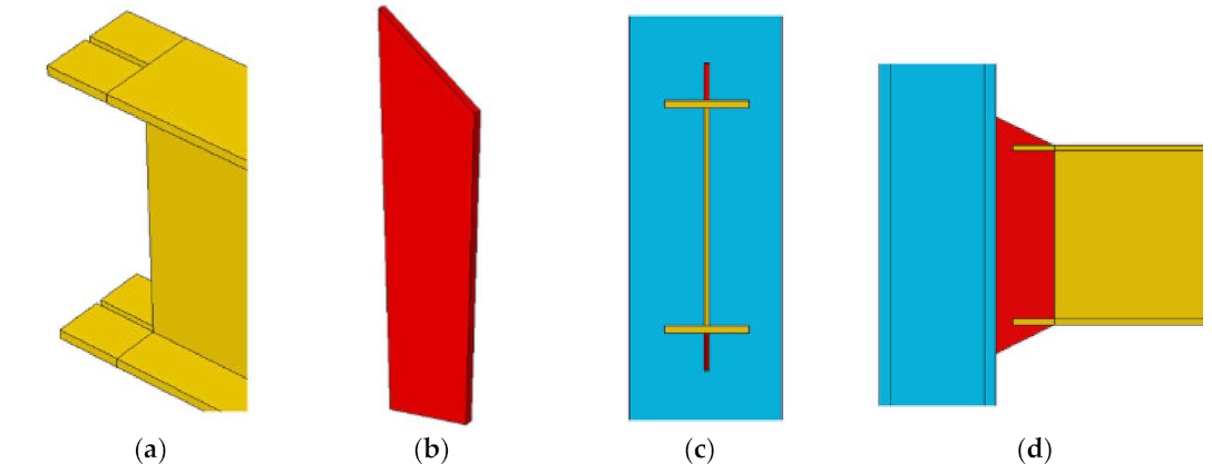
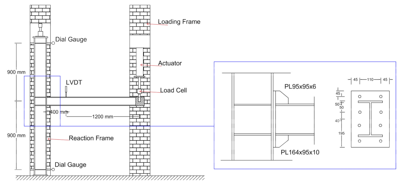
2.2.2. Second Part of Validation

In this section, seven experimental test models from previous studies were selected for simulation and validation purposes. One of these specimens was a one-floor, one-span frame (SPSW2), which was tested by Lubell [8]. The other three specimens were with ½ scale on three-floor, one-span frame specimens (SC2T, SC4T, SC6T) studied by Park et al. [31]. The main difference in these three specimens was in the steel wall thickness, resulting in a general behavioral change of the system from bending to the shear failure mode. The three remaining specimens were of the one-span, one-floor frame type, studied by Vian et al. [9]. In these specimens, steel walls had several circular openings. Selected specimens included a wide range of single and multiple floor frames, moment, and shear failure modes, walls with suitable and insufficient design approach with weak boundary elements. Figure 5 shows the numerical FE models’ geometrical shapes. The sections and mechanical specifications of materials had been given in Table 1.

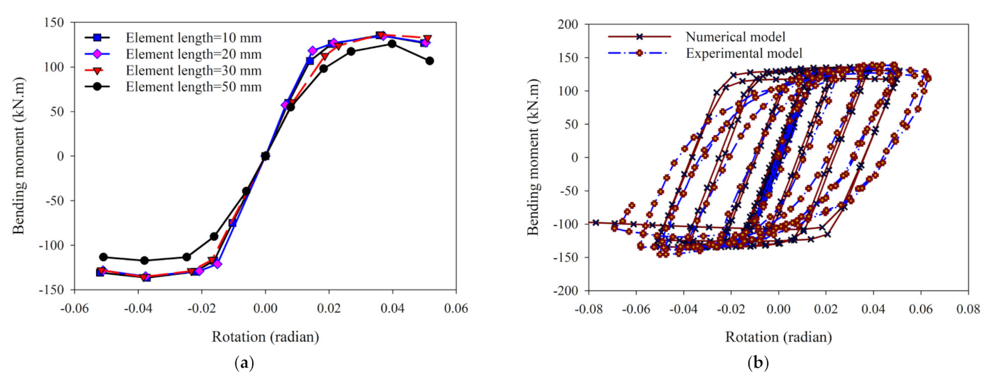
Specifications of Elements and Sensitivity Analysis

HBE, VBE, and infill plate elements had been modeled using the S4R element [25]. The S4R element is a four-node shell of the first-order type with six degrees of freedom for each node [32]. In all numerical models, the hourglass control method was used for the ABAQUS FE program [25] to consider moment and membrane stiffness, whereas boundary elements joined to steel plate walls had been welded. To do so, it is presumed that the steel wall plate is directly connected to HBE and VBE. The meshing model had automatically been considered for the entire structure of the program. Pushover non-linear static analysis was conducted, and certain criteria were considered to determine the size and number of meshes. These parameters included maximum general displacement of the system, maximum Von Mises stress, roof displacement, and base shear. All program warnings were evaluated in all loading stages during analysis. The presented numerical model was in conformity to the SC6T experimental specimen of Park et al. [31]. As it is observed, by an increasing number of elements, the general quality of elements is promoted, and the maximum Von Mises stress is converged. For some of the mentioned parameters, a limited lack of smoothness is seen. However, the calculated errors in all cases are less than 0.5% (except for the total displacement, which is less than 1.5%). Therefore, it is used as per Mesh No. 3 in Table 2 for analyses.

Initial Imperfection

Initial imperfection was considered in steel sheets based on two cases: (i) in fact, frame-filling steel plates are exposed to limited deformation due to manufacturing and displacement process; and (ii) analysis shall face non-linear buckling. Its reason is for the hard work to calculate the fully smooth plates’ initial buckling, in which case several convergence problems shall emerge. Therefore, calculating initial geometrical incompleteness manually both in terms of execution and analysis is mandatory. Various values were considered to study the effect of such an initial geometrical imperfection effect. The initial imperfection was determined based on the elastic buckling mode shape. Maximum buckling values vary between 0.01 and 2% of plate width. On the other hand, in a study conducted by Alinia and Sarraf Shirazi [33], they argued that due to the thin nature of steel shear walls, these buckle in the very early stages and their post-buckling behavior will not have a significant effect on initial geometrical imperfection level imposed to the model. Apart from the post-buckling behavior, initial local buckling is one of the essential aspects of this system behavior, which shall be considered. In Figure 6, the results of the analysis up to steel plate yield have been shown. A little difference is seen in the base shear force—roof displacement relationship. The stiffness–displacement graph provides more details on buckling behavior during the early stage, as shown in Figure 6b. As may be seen, in case the initial geometrical imperfection value is too large, then the buckling is not identified in the early stages using numerical modeling. Therefore, 1% as geometrical imperfection was chosen for the numerical model to compare with experimental specimen initial stiffness. Finally, according to the experimental results, a 1% value was selected for considering the initial geometric imperfection.

Materials Constitutive Model

The stress–strain curves in two different types of loading (i.e., monotonic and cyclic) may be different. Under cyclic loading, the material’s response continues to achieve sustainability. Considering the material nature and stability upon loading commencement, the materials may experience hardening/softening under loading. To use structural steel commonly, it is expected that strain hardening is accompanied by increased plastic strain during cyclic loading. Simultaneously, it is expected that the Bauschinger effect, as one of the common softening phenomena during cyclic loading, is seen during reverse loading.
Apart from the simple complete elastoplastic model, with or without strain hardening, different materials constitutive models have been suggested to identify stress–strain response for monotonic and cyclic loading statuses, of which the Ramberg–Osgood [34] and the Menegotto–Pinto [35] may be mentioned. Due to profitable simplicity and limited calculation time, the bilinear and trilinear model is more applicable and popular than the real stress–strain curve. However, such a simplifying model cannot always be able to express the cyclic behavior well. Often, exponential materials models may better express strain hardening in cyclic loading. Therefore, in this study, the Ramberg–Osgood equation is used to describe the non-linear relationship between stress and strain. It is especially useful for metals that harden with plastic deformation. In Figure 7, the stress–strain curves for all steel materials in this paper are presented.

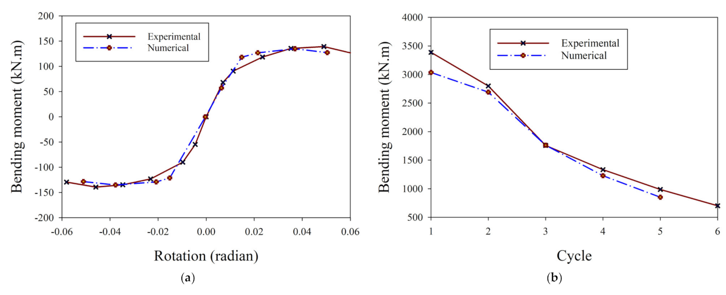
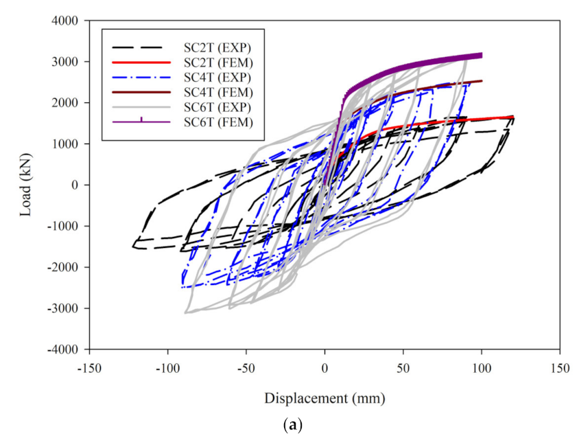
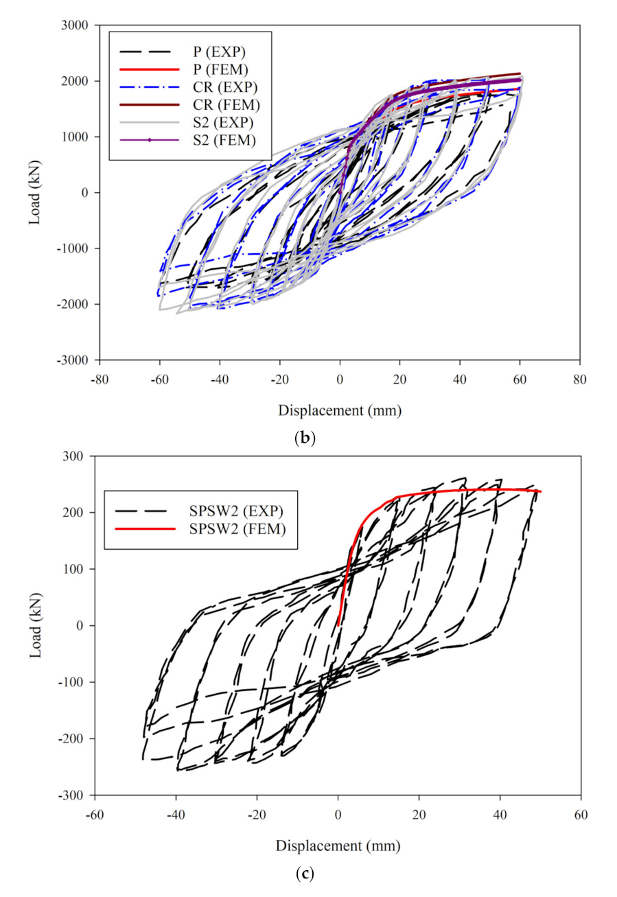
Comparing Numerical and Validation Models Results

Numerical models’ validation was investigated in terms of different aspects considering previous experimental studies and FE numerical models. According to Figure 8, a comparison has been conducted between the results of the test (experimental) specimen results exposed to cyclic loading and the numerical model exposed monotonic loading, to enable estimating experimental pushover chart with proper accuracy. The suggested models were correctly able to provide useful information on critical areas such as column yield area, bending deformations at corners, and steel wall plate deformation. In Table 3, a comparison has been presented for all models in the form of initial stiffness and maximum lateral force values.

3. Results

3.1. Investigating Adequacy and Adjustments in Original Model

A parametric study was conducted in the following to examine the effect of the connection plate effect at the beam to column joint on SPSW system behavior. The FE models were made as per AISC [18] regulations, and the SPSW systems were made using a PMC and were both exposed to monotonic loading. The analytical model was based on the experimental three-floor frame model of Park et al. [31]. All three SC2T, SC4T, and SC6T models were put into non-linear static analysis in two forms. In the first form, there was a beam to column direct joint as per validated models, while in the second, a PMC was used as per Figure 9. The shape of these plates was trapezoidal, and the geometrical details thereof have been given in Figure 9. Notably, the geometrical details of this plate have been selected as per recommendations given by a relevant study conducted by Qian and Astaneh-Asl [36]. On the other hand, the connection between the beam and the steel plate wall was rigid, and the infill wall was quite close to the column and had no direct interaction with the vertical elements [37]. Disconnecting the steel plate shear wall from the columns resulted in some important effects. The columns developed much smaller bending moments and axial forces and remained straight and essentially elastic. Therefore, there was a slight loss of shear capacity of the steel plate shear wall.
In Figure 10, a comparison between the two models’ behavior in terms of yield mechanism and plastic hinge formation had been given in the 3% drift ratio. Therefore, it was seen that using a yielding plate connection as a beam to column connection and providing a distance of 5 mm separation of the steel plate wall from VBE managed to keep the plastic region at the PMC, and this plate acts as a fuse. In the original model (Figure 10a), it is seen upon the end of loading that all structural members play a role in energy absorption and all these members’ plastic regions have been developed.
In Figure 11, a comparison had been conducted between the roof lateral force–displacement chart for original and adjusted models. Considering the foregoing comparison, and notwithstanding acquiring desirable results on the method of formation of plastic zones in the system, it was seen that the original model stiffness is approximately 50% higher than that of a modified model, and the load-bearing capacity is also bigger for 80%.

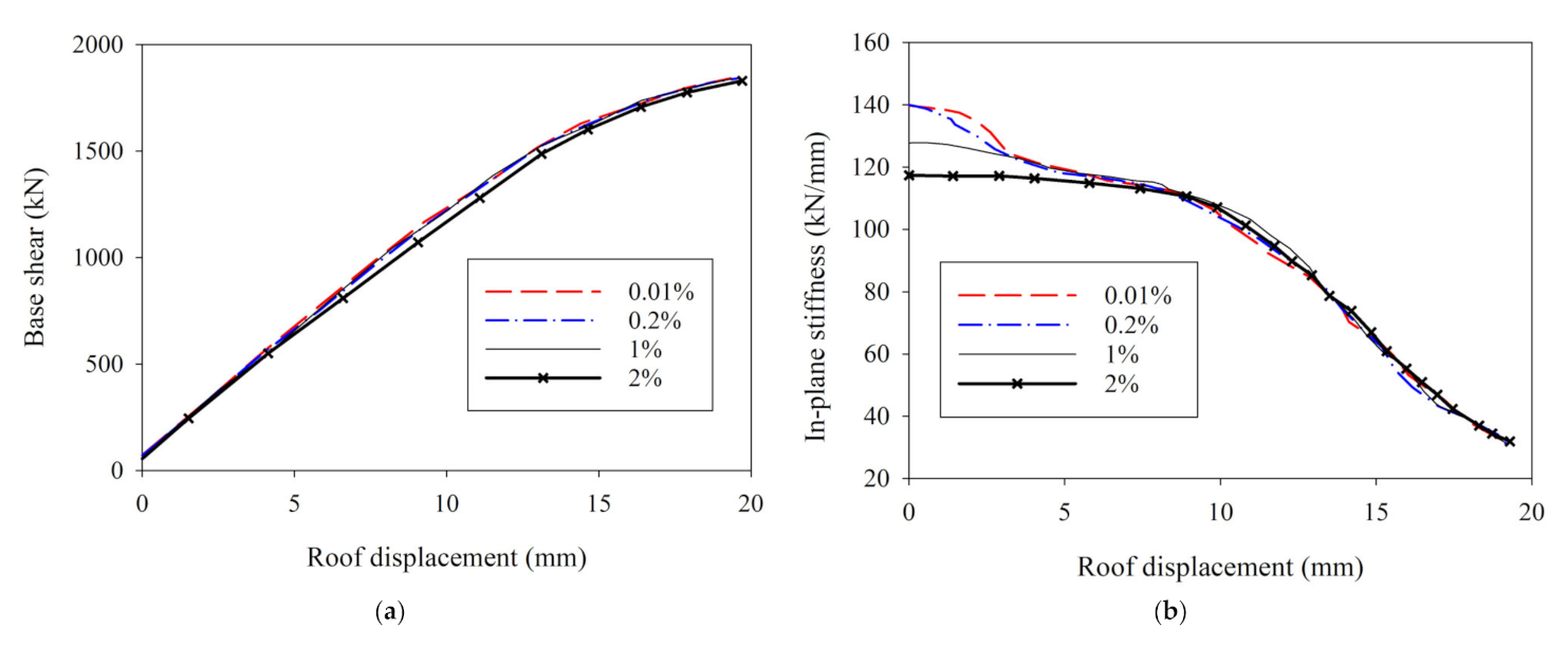
3.2. Lateral Stiffness Effect

According to Figure 10 and Figure 11, certain adjustments were given to promote the performance and capacity of the previous system. Vertical edge stiffener has been utilised at SPSW edges to prevent the free edges out-of-plane deformation (obviously visible on 3rd floor), delay SPSW elastic buckling prior to applying the main load, and participate of SPSW in the formation of plastic hinge. The width and thickness of these stiffener strips are 100 mm and 8 mm, respectively. The philosophy of using the strengthening method was based on the failure mechanism for plate girders. In all models, the stiffener was only connected directly to the beam. In Figure 12, the load–displacement relationship was shown for both types of models.
Considering the findings, it was seen that the discontinuity between SPSW and VBE resulted in two important effects: (a) columns were exposed to limited flexural moments and axial forces, and they remained in an elastic region without deformation; (b) limited loss was seen in SPSW load-bearing capacity, which was due to reduced tension field region width, which in turn resulted in a decline in the shear loads tolerated by VBE due to separating SPSW. The decrease in flexural demand in columns was one of the quite important advantages of this connection method, which had well been able to address the disadvantages of these common SPSWs, which were heavy and excessively big as per the design guidelines.
A limited decrease in shear capacity was easily possible through selecting a thicker steel plate or by taking benefit from strong lateral stiffeners. By increasing the thickness of the wall steel plate, the shear strength and stiffness increased. On the other hand, the lateral stiffeners had larger flexural stiffness and in-plane strength, which may extend the tension field area and provide excessive lateral strength through developing plastic hinges.

3.3. Effect of Connection Plate Thickness

The main parameter in an analysis at this part was the PMC thickness, which was considered as 6.5, 13, and 26 mm. Different thicknesses of the PMC resulted in various plastic moment capacities and variable rotational stiffness for the beam to column joints. In Figure 13, the pushover curves had been given as per the SC4T model using three different values for PMC. As expected, a change in the connection plate thickness mainly affected the frame behavior and had a limited effect on the steel wall capacity. Therefore, separating the SPSW and VBE enabled designers to easily decide on selecting a relative share of steel walls for tolerating shear. In accordance with Figure 13, by increasing the thickness from 6.5 to 13 mm, the lateral load-bearing capacity and initial stiffness increased by 1.7 and 1.8 times, respectively. If the thickness of the connection plate is quadrupled, the load capacity and initial stiffness will increase by 2 and 3.3 times, respectively. Furthermore, the value of energy absorption was enhanced by 2.5 times.
Generally, the system had satisfactory performance, which may be due to showing relatively equal strength and stiffness with the model where the beam was directly welded to the column. By changing in geometry and thickness of the connection plate and relevant ductility, the desired rotational stiffness and flexural strength may be achieved. Among the three introduced values for connection plate thickness, that of 26 mm had the best value in terms of performance.

3.4. Effects of Free Length

Lateral instability of the thin connection plate has a negative effect on the performance of SPSW. The ratio of b/t restrains the local buckling of thin plates. In accordance with ANSI/AISC 360-10 [19], the b/t ratio smaller than 25 is not an important issue for a compressive element. By decreasing the free gusset length, the overall shear capacity of the beam-to-column connection increased, and there were fewer out-of-plane deformations of the gusset plate. Assuming an effective length factor of 0.75, with a limiting slenderness ratio factor of 0.8 to account for the cyclic effect, this slenderness requirement can be incorporated to an Lfp/tp of 7.696 (calculated from 0.75 × Lfp/tp ≤ 0.8 × 25), proving that this requirement is automatically satisfied by the above-recommended free-connection length range. The behavior generally agrees with the parametric analysis of the shallow beam. A shorter Lfp relates to greater local demand. The global curves of hysteresis are similar, as both cases were developed to follow the same strength requirements.

3.5. Effects of the Ratio of Plastic Bending Moment

The ratio of the connection’s plastic moment capacity to that of the beam (i.e., Mpc/Mpb) was defined as a moment capacity ratio. This had been shown to have a marginal influence on the entire behavior of load-elongation, but it may induce various system yield mechanisms. Almost all inelastic deformation in cases with Mpc/Mpb < 1 was localised in the plate that acts as a fuse, while the beam remained elastic (Figure 14a). However, for cases of Mpc/Mpb > 1, the beam yielded in comparatively wide regions (Figure 14b).
The beam failure was unfavorable and contradicted the performance requirements established for the connection. Hence, it was necessary to maintain the inelastic bending moment ratio Mpc/Mpb below 1, in order to completely accomplish the desired performance expectations.
According to the previous two situations, Figure 15 shows the plastic strain changes in the two members of the beam and the connection plate. According to status (a), the plastic strain on the connection plate has exceeded the allowable limit (0.15). This situation becomes more critical when the plastic bending capacity of the connection plate is higher than that of the beam. So, the plastic strain of the beam also exceeds its limit (Situation (b) in Figure 14).

3.6. Suggesting Steel Wall Shear Capacity Formula

An unbuckled steel wall that was exposed to shear, compressive, and tension stresses was made with angles of 45 and 135°. Wagner [5] suggested a new load-bearing mechanism in the form of a tilted tension field, which was developed to tolerate excessive load upon plate buckling. First of all, Wagner [5] determined the tension field angle on an aluminum plate. The main assumption was that flanges may tolerate lateral load from the tension field with large deformations.
Results of the study conducted by Thorburn et al. [38] (presuming that solely forces are absorbed by the system) to determine the tension field angle and the shear capacity resulted in the following formulas:
α = cot 1 + t p L c 2 A c / 1 + t p h b A b
V = 0.5 f y p t p L c sin 2 α
where α, V, tp, Lc, Ac, hb, Ab, and fyp are the tension field angle, the shear capacity, the steel wall plate thickness, the net distance between columns, the boundary column area, the net distance between beams, the boundary beam area, and the steel wall plate yield stress, respectively.
Timler and Kulak [6] realised the necessity of adding the peripheral elements flexural strain energy (especially columns). In addition to the strain energy developed by the web plate tension field action, they considered the axial strain energy of beams and columns as well. Eventually, their achievement was given in AISC [19]. The following formulas could predict with good accuracy for rigid boundary elements or with a tension field angle of 45°.
α = cot 1 + t p L 2 A c 1 + t p h 1 A b + h 3 360 I c L
V = 0.5 f y p t p L c sin 2 α
where L, h, and Ic are the center-to-center distance of columns, the floor height, and the peripheral column moment of inertia, respectively.
Now, supposing that the beams are rigid and the columns are ductile, the tension field angle will not be related to the boundary element details anymore and shall solely be related to steel wall-size ratios.
α = 0.5 tan 1 L h
V = 0.5 f y p t p L tan α
By removing the boundary elements contribution, the foregoing expressions suggest a conservative estimation of the tension field angle. For instance, Formula (5) predicted an angle of 28°, while the angle observed by experimental studies [39] and the herein numerical studies was between 30 and 35°.

4. Conclusions

In this study, a cost-effective and good-performance approach of a thin SPSW equipped with a yielding PMC was presented and studied in the form of 3D FE models using the ABAQUS software under non-linear static analysis. Incorporating the PMC into the SPSW system, and separating the infill wall from the boundary columns, a SPSW system was developed. A model of the moment connection was validated using a connection plate in the plane of the beam web and column web together with eight experimental specimens, and the numerical model’s performance accuracy was ensured. Extensive numerical models were simulated from the SPSW, and the effect of parameters such as the connection plate thickness and the existence of vertical edge stiffeners on the system behavior were studied. The main study findings are given in the following.
1.
The numerical model was validated using eight experimental specimens of SPSW considering materials’ different mechanical specifications, different number of floors, and shear and flexural yield modes. The difference between the numerical model and experimental specimens was achieved to be less than 7% in terms of load-bearing capacity.
2.
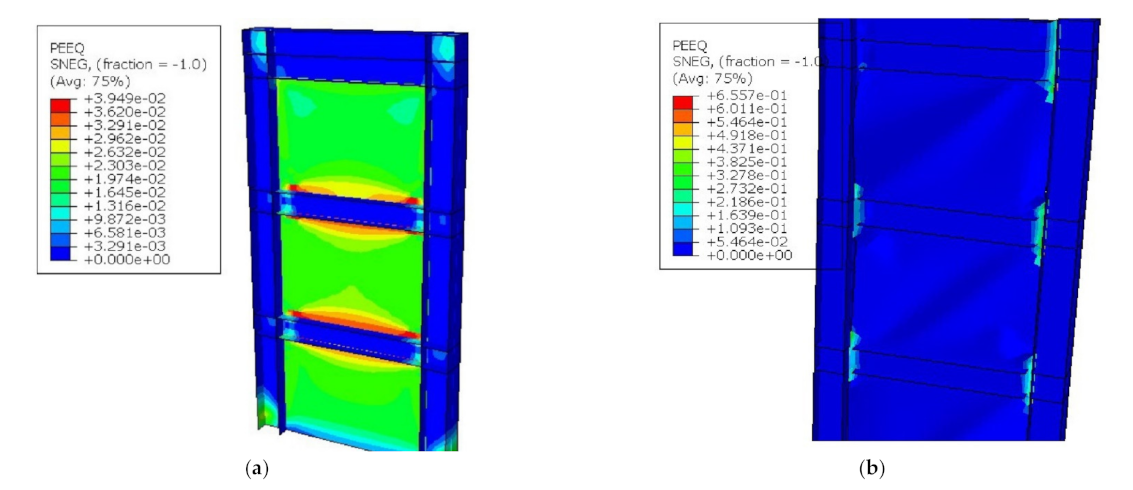
Using an absorber connection plate and the existence of a narrow gap between the SPSW and VBE resulted in the development of a plastic hinge in the panel zone and acted as a fuse.
3.
By using connection plate and vertical edge stiffeners, numerical models were able to provide elastic stiffness and capacity equal to an experimental specimen of the direct beam to column joint, which in turn caused that the columns are exposed to limited axial forces and bending moments and remain in an elastic region without deformation.
4.
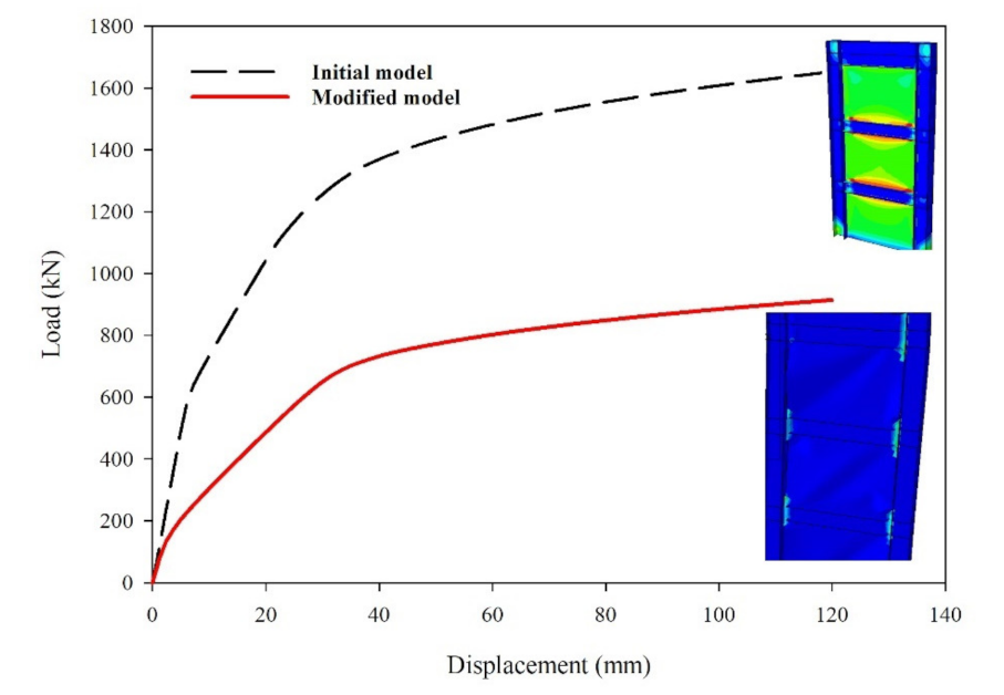
Using vertical side stiffeners increases the bearing capacity and energy absorption in the normal SPSW, which has a narrow gap to the columns. The load-bearing capacity and initial stiffness in the modified model increased by 80% and 50%, respectively.
5.
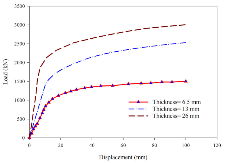
The best performance of the connection plate was observed for a plate with a thickness of 26 mm. The load-bearing capacity, energy absorption, and elastic stiffness increased approximately 2, 2.5, and 3.3 times, respectively, as the plate thickness increased (from 6.5 to 26 mm).
6.
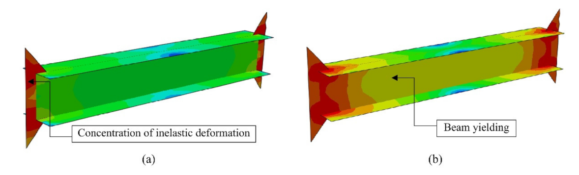
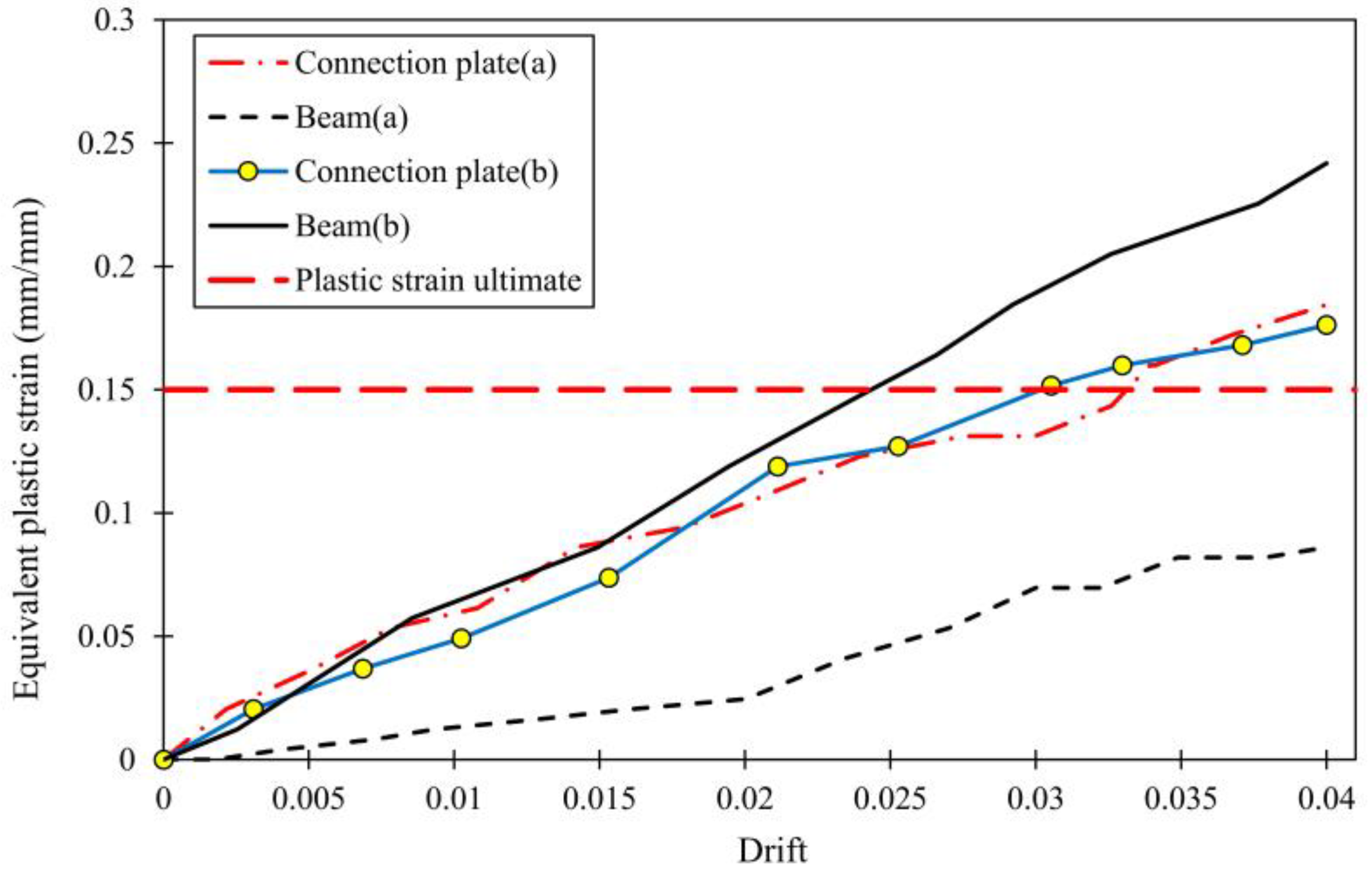
The ratio of free length to thickness of the PMC requirement can be incorporated to a Lfp/tp of 7.696. In addition, by increasing the bending moment capacity ratio over than one, yielding of the beam occurred. In other words, all inelastic deformation is concentrated in the PMC for the ratio below one, and the other structural members are maintained in an elastic state.
7.
By removing peripheral elements share, the expressions and formulations given in the AISC provide a conservative estimation of the tension field. According to the formulas, a 28° angle is indicated, whilst the angle observed by experimental studies and the herein numerical studies was between 30 and 35°.

Author Contributions

Conceptualization, S.M.S., S.R., M.H., D.-P.N.K., and M.E.-J.; methodology, S.M.S., S.R., M.H., D.-P.N.K., and M.E.-J.; software, S.M.S., S.R. and M.E.-J.; validation, S.M.S., S.R., M.H., D.-P.N.K., and M.E.-J.; formal analysis, S.M.S., S.R., M.H., D.-P.N.K. and M.E.-J.; investigation, S.M.S., S.R., M.H., D.-P.N.K., and M.E.-J.; resources, S.M.S., S.R., M.H., D.-P.N.K., and M.E.-J.; data curation, S.M.S., S.R., M.H., D.-P.N.K., and M.E.-J.; writing—original draft preparation, S.M.S., S.R., M.H., D.-P.N.K., and M.E.-J.; writing—review and editing, S.M.S., S.R., M.H., D.-P.N.K., and M.E.-J.; visualisation, S.M.S., S.R., M.H., D.-P.N.K. and M.E.-J.; supervision, S.R., D.-P.N.K., and M.E.-J. All authors have read and agreed to the published version of the manuscript.

Funding

This research received no external funding.

Institutional Review Board Statement

Not applicable.

Informed Consent Statement

Not applicable.

Data Availability Statement

All the data supporting the results were provided within the article.

Conflicts of Interest

The authors declare no conflict of interest.

References

  1. Basler, K.; Thürlimann, B. Strength of plate girders in bending (Lehigh University, Fritz Engineering Laboratory). J. Struct. Div. 1960, 87, 153–184. [Google Scholar] [CrossRef]
  2. American Institute of Steel Construction. ANSI/AISC 341-05, Seismic Provisions for Structural Steel Buildings; American Institute of Steel Construction Inc. (AISC, Inc.): Chicago, IL, USA, 2005. [Google Scholar]
  3. Canadian Standards Association. Limit States Design of Steel Structures (CSA-S16-01); Canadian Standards Association (CSA): Mississauga, ON, Canada, 2001. [Google Scholar]
  4. Federal Emergency Management Agency. NEHRP Recommended Provisions for Seismic Regulations for New Buildings and Other Structures; FEMA, 2003. Available online: https://www.nehrp.gov/library/ (accessed on 1 February 2021).
  5. Wagner, H. Flat Sheet Metal Girders with Very Thin Webs, Part III: Sheet Metal Girders with Spars Resistant to Bending-The Stress in Uprights-Diagonal Tension Fields; National Advisory Committee for Aeronautics: Washington, DC, USA, 1931. Available online: http://hdl.handle.net/2060/19930094810 (accessed on 1 February 2021).
  6. Timler, P.A.; Kulak, G.L. Experimental Study of Steel Plate Shear Walls; Structural Engineering Report No. 114; Dept. of Civil Engineering, The University of Alberta: Edmonton, AB, Canada, 1983. [Google Scholar] [CrossRef]
  7. Driver, R.G. Seismic Behavior of Steel Plate Shear Walls. Ph.D. Thesis, Dept. of Civil, and Environmental Engineering, University of Alberta, Edmonton, AB, Canada, 1997. [Google Scholar] [CrossRef]
  8. Lubell, A.S. Performance of Unstiffened Steel Plate Shear Walls under Cyclic Quasi-Static Loading. Master’s Thesis, Department of Civil Engineering, University of British Columbia, Vancouver, BC, Canada, 1997. [Google Scholar] [CrossRef]
  9. Vian, D.; Bruneau, M.; Tsai, K.-C.; Lin, Y.-C. Special perforated steel plate shear walls with reduced beam section anchor beams. I: Experimental investigation. J. Struct. Eng. 2009, 135, 211–220. [Google Scholar] [CrossRef]
  10. Purba, R.; Bruneau, M. Finite-element investigation and design recommendations for perforated steel plate shear walls. J. Struct. Eng. 2009, 135, 1367–1376. [Google Scholar] [CrossRef]
  11. Sabouri-Ghomi, S.; Asad Sajjadi, S.R. Experimental and theoretical studies of steel shear walls with and without stiffeners. J. Constr. Steel Res. 2012, 75, 152–159. [Google Scholar] [CrossRef]
  12. Hosseinzadeh, S.A.A.; Tehranizadeh, M. Behavioral characteristics of code designed steel plate shear wall systems. J. Constr. Steel Res. 2012, 99, 72–84. [Google Scholar] [CrossRef]
  13. Machaly, E.B.; Safar, S.S.; Amer, M.A. Numerical investigation on ultimate shear strength of steel plate shear walls. Thin-Walled Struct. 2014, 84, 78–90. [Google Scholar] [CrossRef]
  14. Du, Y.; Hao, J.; Yu, J.; Yu, H.; Deng, B.; Lv, D.; Liang, Z. Seismic performance of a repaired thin steel plate shear wall structure. J. Constr. Steel Res. 2018, 151, 194–203. [Google Scholar] [CrossRef]
  15. Qu, B.; Bruneau, M.; Lin, C.-H.; Tsai, K.-C. Testing of full-scale two-story steel plate shear wall with reduced beam section connections and composite floors. J. Struct. Eng. 2008, 134, 364–373. [Google Scholar] [CrossRef]
  16. Sabouri-Ghomi, S.; Ventura, C.E.; Kharrazi, M.H. Shear analysis and design of ductile steel plate walls. J. Struct. Eng. 2005, 131, 878–889. [Google Scholar] [CrossRef]
  17. Hitaka, T.; Matsui, C. Experimental study on steel shear wall with slits. J. Struct. Eng. 2003, 129, 586–595. [Google Scholar] [CrossRef]
  18. American Institute of Steel Construction. ANSI/AISC 341-10, Seismic Provisions for Structural Steel Buildings; American Institute of Steel Construction Inc. (AISC, Inc.): Chicago, IL, USA, 2010. [Google Scholar]
  19. American Institute of Steel Construction. ANSI/AISC 360-16, Specification for Structural Steel Buildings; American Institute of Steel Construction Inc. (AISC, Inc.): Chicago, IL, USA, 2016. [Google Scholar]
  20. Eatherton, M. Design and construction of steel plate shear walls. In Proceedings of the Eighth US National Conference on Earthquake Engineering, San Francisco, CA, USA, 18–22 April 2006; Available online: https://eatherton.cee.vt.edu/publications (accessed on 1 February 2021).
  21. Shi, Y.; Astaneh-Asl, A. Lateral stiffness of steel shear wall systems. In Proceedings of the Structures Congress 2008: Crossing Borders, Vancouver, BC, Canada, 24–26 April 2008; pp. 1–10. [Google Scholar] [CrossRef]
  22. Zhao, Q.; Astaneh-Asl, A. Experimental and analytical studies of a steel plate shear wall system. In Proceedings of the Structures Congress 2008: Crossing Borders, Vancouver, BC, Canada, 24–26 April 2008; pp. 1–10. [Google Scholar] [CrossRef]
  23. Li, C.-H.; Tsai, K.-C.; Lin, C.-H.; Chen, P.-C. Cyclic tests of four two-story narrow steel plate shear walls. Part 2: Experimental results and design implications. Earthq. Eng. Struct. Dyn. 2010, 39, 801–826. [Google Scholar] [CrossRef]
  24. Nie, J.; Fan, J.; Liu, X.; Huang, Y. Comparative study on steel plate shear walls used in a high-rise building. J. Struct. Eng. 2013, 139, 85–97. [Google Scholar] [CrossRef]
  25. ABAQUS, Version 6.14 Documentation; Dassault Systemes Simulia Corporation: Providence, RI, USA, 2014; Available online: http://130.149.89.49:2080/v6.14/ (accessed on 1 February 2021).
  26. Horne, M.R.; Morris, L.J. Plastic Design of Low-Rise Frames; MIT Press: Cambridge, MA, USA, 1983; Available online: https://mitpress.mit.edu/books/plastic-design-low-rise-frames (accessed on 1 February 2021).
  27. Sabouri-Ghomi, S.; Roberts, T.M. Nonlinear dynamic analysis of steel plate shear walls including shear and bending deformations. Eng. Struct. 1992, 14, 309–317. [Google Scholar] [CrossRef]
  28. Guo, B.; Gu, Q.; Liu, F. Experimental behavior of stiffened and unstiffened end-plate connections under cyclic loading. J. Struct. Eng. 2006, 132, 1352–1357. [Google Scholar] [CrossRef]
  29. Ebadi-Jamkhaneh, M.; Kafi, M.A. Experimental and numerical study of octagonal composite column subject to various loading. Period. Polytech. Civ. 2018, 62, 413–422. [Google Scholar] [CrossRef] [Green Version]
  30. Koloo, F.A.; Badakhshan, A.; Fallahnejad, H.; Jamkhaneh, M.E.; Ahmadi, M. Investigation of proposed concrete filled steel tube connections under reversed cyclic loading. Int. J. Steel Struct. 2018, 18, 163–177. [Google Scholar] [CrossRef]
  31. Park, H.-G.; Kwack, J.-H.; Jeon, S.-W.; Kim, W.-K.; Choi, I.-R. Framed steel plate wall behavior under cyclic lateral loading. J. Struct. Eng. 2007, 133, 378–388. [Google Scholar] [CrossRef]
  32. Jamkhaneh, M.E.; Ahmadi, M.; Sadeghian, P. Simplified relations for confinement factors of partially and highly confined areas of concrete in partially encased composite columns. Eng. Struct. 2020, 208, 110303. [Google Scholar] [CrossRef]
  33. Alinia, M.M.; Sarraf Shirazi, R. On the design of stiffeners in steel plate shear walls. J. Constr. Steel Res. 2009, 65, 2069–2077. [Google Scholar] [CrossRef]
  34. Ramberg, W.; Osgood, W.R. Description of Stress-Strain Curves by Three Parameters. 1943. Available online: http://hdl.handle.net/2060/19930081614 (accessed on 1 February 2021).
  35. Menegotto, M.; Pinto, P.E. Method of analysis for cyclically loaded RC plane frames including changes in geometry and non-elastic behavior of elements under combined normal force and bending. In Proceedings of the of IABSE Symposium on Resistance and Ultimate Deformability of Structures Acted on by Well-Defined Repeated Loads, Lisbon, Portugal, 2–5 September 1973; Volume 11, pp. 15–22. [Google Scholar] [CrossRef] [Green Version]
  36. Qian, X.; Astaneh-Asl, A. Development of a high-performance steel plate shear wall system. IJEIE 2016, 1, 57–80. Available online: https://escholarship.org/uc/item/16t3r6qk (accessed on 1 February 2021). [CrossRef]
  37. Choi, I.-R.; Park, H.-G. Steel plate shear walls with various infill plate designs. J. Struct. Eng. 2009, 135, 785–796. [Google Scholar] [CrossRef]
  38. Thorburn, L.J.; Montgomery, C.J.; Kulak, G.L. Analysis of Steel Plate SHEAR Walls; Structural Engineering Report No. 107; Dept. of Civil Engineering, The University of Alberta: Edmonton, AB, Canada, 1983. [Google Scholar] [CrossRef]
  39. Vatansever, C.; Yardimci, N. Experimental investigation of thin steel plate shear walls with different infill-to-boundary frame connections. Steel Compos. Struct. 2011, 11, 251–271. [Google Scholar] [CrossRef]
Figure 1. Connection with an absorber plate: (a) cut beam, (b) connection plate, (c) front view, and (d) side view.
Metals 11 00604 g001
Figure 2. Geometrical details of the specimen [28] (units are given in mm, LVDT: linear variable differential transformer, PL: plate).
Metals 11 00604 g002
Figure 3. Load–displacement curves of the numerical model and the experimental specimen: (a) sensitivity analysis and (b) bending moment-rotation curves.
Metals 11 00604 g003
Figure 4. Stiffness changes in different cycles: (a) bending moment–rotation relationship, and (b) stiffness changes in different cycles.
Metals 11 00604 g004
Figure 5. Selected experimental specimens for numerical simulations: (a) tested specimens by Park et al. [31], (b) specimen SPSW2 tested by Lubell [8], and (c) tested specimens by Vian et al. [9].
Metals 11 00604 g005
Figure 6. Effect of geometrical imperfection on the behavior of steel plate shear wall system: (a) base shear–roof displacement relationship and (b) stiffness changes rather than roof displacement.
Metals 11 00604 g006
Figure 7. Stress–strain curves of steel materials.
Metals 11 00604 g007
Figure 8. Comparison between numerical models (FEM) and experimental specimens (EXP): (a) comparison of load–displacement curves between numerical results and test results [31], (b) comparison of load–displacement curves between numerical results and test results [9], and (c) comparison of load–displacement curves between numerical results and test results [8].
Metals 11 00604 g008aMetals 11 00604 g008b
Figure 9. Geometrical features and location of the absorber plate in the steel plate shear walls (SPSW) system.
Metals 11 00604 g009
Figure 10. Forming of plastic hinge location in the initial and modified models: (a) original model and (b) modified model (PEEQ: represented in ABAQUS as the equivalent plastic strain, SNEG: surface negative).
Metals 11 00604 g010
Figure 11. Comparison of load–displacement curves between the initial and corrected models.
Metals 11 00604 g011
Figure 12. Load–displacement curves of initial models and corrected models equipped with stiffener plates.
Metals 11 00604 g012
Figure 13. Load–displacement curves of numerical models with different thicknesses of plates.
Metals 11 00604 g013
Figure 14. Effect of the ratio of plastic bending moment on the failure mechanism of the plate as a fuse and the beam: (a) concentration of plastic hinge in the connection plate and (b) beam yielding.
Metals 11 00604 g014
Figure 15. Comparison of equivalent plastic strain.
Metals 11 00604 g015
Table 1. Geometrical dimensions of structural sections and mechanical properties of materials.
Ref.Specimen NameFyp (MPa)Fu (MPa)Fy (MPa)tcw (mm)tcf (mm)hc (mm)wcf (mm)tp (mm)tbw (mm)tbf (mm)hb (mm)wbf (mm)
Park et al. [31]SC2T240450240202025025021616200200
SC4T330510330202025025041616200200
SC6T330510330202025025061616200200
Vian et al. [9]S2, P, CR1655503451319.24701902.61019.2466190
Lubell [8]SPSW23205553804.36.676591.54.36.67659
wbf = width of beam flange, hb = height of a beam, tbf = thickness of beam flange, tbw = thickness of beam web, tp = thickness of a steel wall plate, wcf = width of column flange, hc = height of column section, tcf = thickness of column flange, tcw = thickness of column web, Fy = yield stress of boundary elements, Fu = ultimate stress of boundary elements, Fyp = yield stress of steel wall plate.
Table 2. Sensitivity analyses of SC6T model.
No.Number of PointsNumber of ElementsElapsed Time (s)Element QualityError Average
Standard DeviationAverageBase ShearRoof DisplacementMax. StressMax. Displacement
1346732763430.16420.91340.32%−0.13%−9.94%−2.34%
2864383076490.06850.96320.11%0.33%−4.03%−2.84%
310,64598928900.1130.96010.22%0.21%−0.05%−1.33%
413,65913,48918760.03690.9844----
Table 3. Comparison between numerical and experimental results.
ParameterModelLubell [8]Vian et al. [9]Park et al. [31]
SPSW2S2CRPSC6TSC4TSC2T
Elastic stiffness (kN/mm)Experimental47.8255.2285.2203.2158.4140.892.3
Numerical44.5253.4293.2215.3165.5137.396.8
Difference (%)−6.9−0.7+2.8+5.9+4.5−2.5+4.8
Maximum load (kN)Experimental250209120631772306324851682
Numerical241201921341859310025311653
Difference (%)−3.6−3.4+3.4+4.9+1.2+1.8−1.7
Publisher’s Note: MDPI stays neutral with regard to jurisdictional claims in published maps and institutional affiliations.

