
Fracture Mechanical Analysis of Thin-Walled Cylindrical Shells with Cracks


School of Mechanics, Civil Engineering and Architecture, Northwestern Polytechnical University, Xi’an 710072, China
*
Author to whom correspondence should be addressed.
Metals 2021, 11(4), 592; https://doi.org/10.3390/met11040592
Submission received: 20 February 2021
/
Revised: 27 March 2021
/
Accepted: 1 April 2021
/
Published: 5 April 2021
(This article belongs to the Special Issue Mechanical, Crack and Fatigue Properties of Tool Steel, Pipe Steel, and Laser Welded Steel)
Abstract
:The fracture mechanical behaviour of thin-walled structures with cracks is highly significant for structural strength design, safety and reliability analysis, and defect evaluation. In this study, the effects of various factors on the fracture parameters, crack initiation angles and plastic zones of thin-walled cylindrical shells with cracks are investigated. First, based on the J-integral and displacement extrapolation methods, the stress intensity factors of thin-walled cylindrical shells with circumferential cracks and compound cracks are studied using linear elastic fracture mechanics, respectively. Second, based on the theory of maximum circumferential tensile stress of compound cracks, the number of singular elements at a crack tip is varied to determine the node of the element corresponding to the maximum circumferential tensile stress, and the initiation angle for a compound crack is predicted. Third, based on the J-integral theory, the size of the plastic zone and J-integral of a thin-walled cylindrical shell with a circumferential crack are analysed, using elastic-plastic fracture mechanics. The results show that the stress in front of a crack tip does not increase after reaching the yield strength and enters the stage of plastic development, and the predicted initiation angle of an oblique crack mainly depends on its original inclination angle. The conclusions have theoretical and engineering significance for the selection of the fracture criteria and determination of the failure modes of thin-walled structures with cracks.
1. Introduction
Reasonably designed thin shells can withstand considerable loads, making them superior to thin plates. Owing to their advantages of good mechanical properties and economic applicability, thin-walled structures are commonly used in many fields, such as machinery, architecture, military, aerospace, and marine engineering. However, the actual strength of a material is much lower than that of its theoretical model owing to the presence of cracks in practice [1]. Engineering accidents are frequently caused by cracks leading to very severe consequences. The safety of thin-walled shell structures with cracks has always been an important issue in engineering. To establish a safety evaluation method, it is necessary to study the fracture mechanical behaviour of thin-walled shells with cracks.
A large number of studies have been conducted on the fracture mechanical behaviour of structures with cracks [2]. Hu and Xie [3] proposed a simple and practical method for determining the stress intensity factor (SIF) of the crack of the irregularly-shaped thin-walled tube. Xie and Wang [4] proposed a simple method to determine the SIFs based on a new concept of crack surface widening energy release rate. Xie et al. [5,6] proposed an analytical and very simple method to determine the SIFs based on a new concept of crack surface widening energy release rate and the principle of virtual work. Bazant [7] presented a justification of Kienzler and Herrmann’s estimate of SIFs of cracked beam and further showed a possibility of improvement by introduction of an additional factor. Dunn et al. [8] presented simple, closed-form expressions for SIFs for cracked I-beams subjected to a bending moment. Xing et al. [9] developed a novel fracture mechanics framework for cracked thin-walled structures based on the Mindlin-Reissner plate theory. Atluri [10] explored the physical interpretations of each of the integrals either in terms of crack-tip energy release rates or simply energy-rate differences in two comparison cracked-bodies. Blackburn [11] investigated the path independent integrals to predict onset of crack instability in an elastic plastic material. Seshadri and Marriott [12] discussed a new and a direct procedure for reference stress determination using the GLOSS R-Node method. Sucharda [13] presented the procedure for the identification of fracture mechanical parameters for a specific concrete with the use of developed inverse analysis combining multi-criteria decision analysis, stochastic modelling and nonlinear analysis. Lei et al. [14] investigated the impact fracture and fragmentation of glass via the 3D combined Finite-Discrete Element Method.
Using the experimental methods and the theory of fracture mechanics, scholars have studied the laws of crack instability and propagation, and put forward the corresponding fracture criteria. Jahromi and Vaziri [15] analysed the instability of cylindrical shells with single and multiple cracks under axial compression. Dyshel [16] carried out the analysis of stability of a cracked cylindrical shell in tension. Estekanchi and Vafai [17] studied the buckling of cylindrical shells with through cracks and proposed a general finite element model. Zhou and Huang [18] developed a method to determine the elastic deflection of the eccentric thin-walled columns containing some model-I cracks. Zhou and Huang [19] developed a close form solution of the maximum deflection for cracked columns with rectangular cross-sections and studied the elastic buckling behaviour and ultimate bearing capacity analytically. Chakherlou et al. [20] investigated the fatigue crack initiation and fatigue crack growth life estimations. Gao and Herrmann [21] used the beam theory estimation to compute SIFs for a circumferentially cracked cylindrical pipe in bending and tension and found good agreement with the exact solutions obtained from complete shell analysis. Moës and Belytschko [22] demonstrated the effectiveness of the extended finite element method by simulations of cohesive crack growth in concrete. Sukumar and Prévost [23] discussed some of the key issues in the X-FEM and describe its implementation within a general-purpose finite element code. Khan and Khraisheh [24] presented a detailed analysis of mixed mode I-II crack initiation angles under different loading conditions using different criteria. Khan and Khraisheh [25] proposed a new criterion for mixed mode I-II crack initiation angles based on the characteristics of the plastic core region surrounding the crack tip.
In the research of thin-walled structures with cracks in service, the following problems still exist. (1) Although there are numerous studies on thin-walled structures with complete components or geometric defects, there are few on those with physical defects. (2) There are various studies on the effects of simple loads, whereas there are fewer studies on eccentric compression and combination of tension and bending moment. (3) There are many studies on the fracture parameters of thin-walled components with mode-I cracks, however, there are only few studies on the fracture parameters in the presence of compound cracks and the prediction of crack initiation angles. (4) At present, the research and theory on linear elastic fracture mechanics is mature, whereas the studies on elastic-plastic fracture mechanics are relatively fewer, and those of plastic zone size are rare.
In this paper, the fracture parameters, plastic zones and crack initiation angles of thin-walled cylindrical shells with cracks are investigated using the finite element method. First, the finite element models of thin-walled cylindrical shells with circumferential cracks and compound cracks are established, respectively, and different loads such as axial tension, eccentric compression and the combination of tension and bending moment are applied. Second, for the constitutive relationship of linear elastic materials, the SIFs of thin-walled cylindrical shells with circumferential cracks and compound cracks are calculated, based on the J-integral and the displacement extrapolation methods, respectively. Subsequently, by applying the theory of maximum circumferential tensile stress of compound cracks, the node of the element corresponding to the maximum circumferential tensile stress is obtained by varying the number of singular elements at the crack tip. Accordingly, the initiation angle of a compound crack is predicted. Third, for the constitutive relationship of elastic-plastic materials, the plastic zone size and J-integral of thin-walled cylindrical shells with circumferential cracks are calculated. Finally, the effects of various factors on the fracture parameters, crack initiation angles and plastic zones are investigated.
2. Theory of Fracture Mechanics
2.1. J-Integral
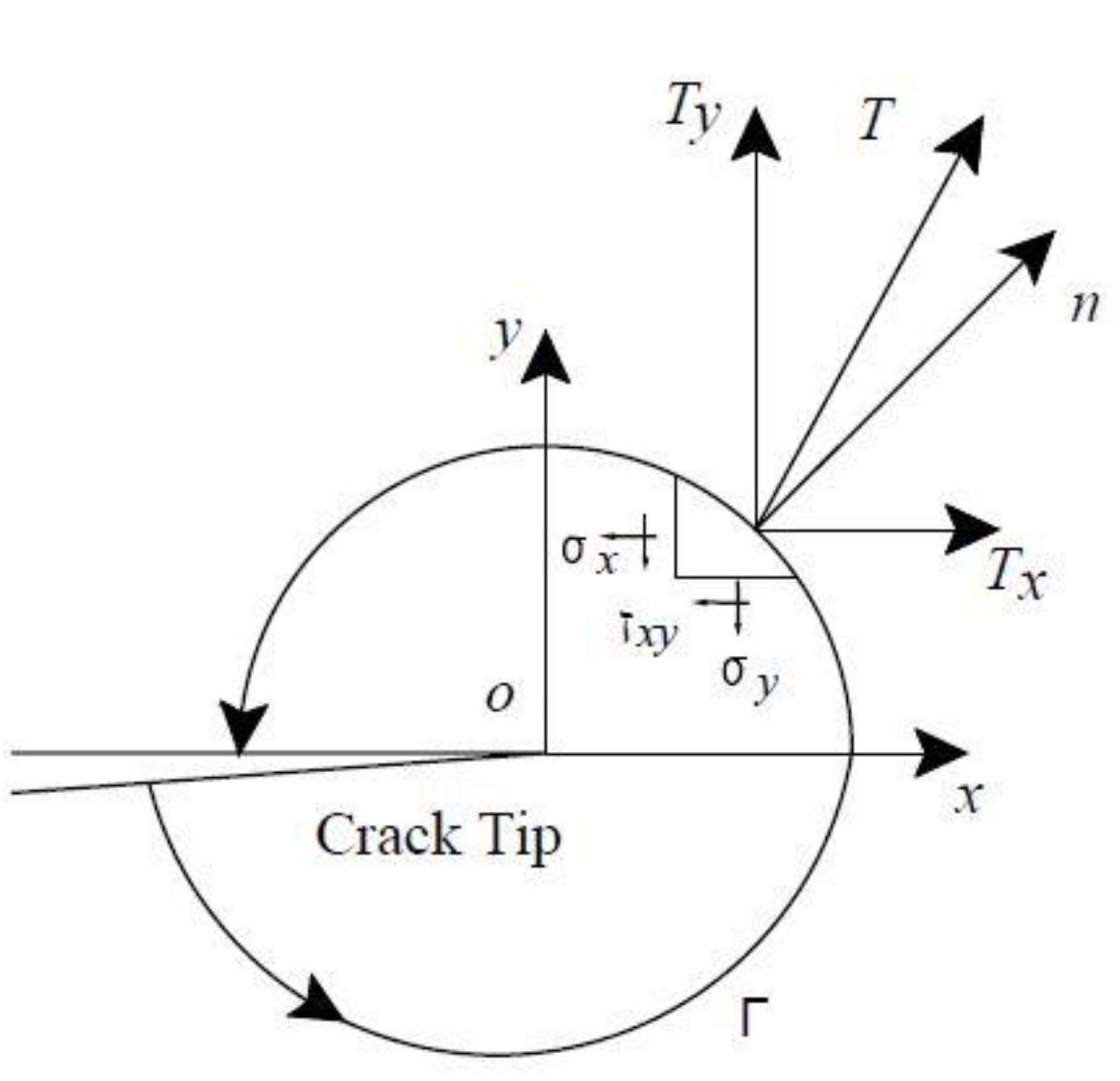
To analyse the strength of the stress and strain field at the crack tip of a cracked body, some line integrals presenting conservation properties are frequently used. J-integral is one such line integrals. It is defined as a line integral around a crack tip, as shown in Figure 1, and expressed as
where is any counter-clockwise loop around the crack tip. is the strain energy density at any point on the loop. The arrow between and is the total traction vector. and are the surface force components along the and directions at any point, respectively. and are the displacement components along the x and y directions at any point, respectively. is the arc element on the loop.
In this paper, the research on J-integral is studied in ANSYS (Ansys Inc., Canonsburg, PA, USA) software and is divided into two modules. For ideal elastic-plastic materials, physical quantities such as strain energy and stress of the elements around the crack front are extracted, and the routine for J-integral calculation is realized by APDL. For linear elastic materials, according to the relationship between J-integral and SIF in linear elastic stage, SIF of thin-walled cylindrical shells with circumferential cracks can be obtained. In the calculation of J-integrals, the strain energy density and strain field of the elements around the crack front are mainly considered. To reduce the calculation error by the maximum extent, the integral paths are selected in a sufficiently wide range to obtain high-accuracy results. Several concentric paths having different lengths are defined around the crack front edge. Subsequently, the calculated results are mapped to each path. The J-integral values are obtained using Equation (1), and their arithmetic mean value is taken as the result.
In this study, the change in the axial stress along the shell thickness direction and the effect of the radial transverse shear force are ignored. Therefore, the loop integral definition of a plane problem is adopted for the calculations. Because of the conservation of the J-integral integral path, the high-stress and strain region at the crack front edge can be avoided in the calculations, and any integral loop far away from the crack tip can be selected, which makes the calculations simple. In the case of linear elasticity, the J-integral is proportional to the square of the SIF.
where and are the elasticity modulus and Poisson’s ratio, respectively.
2.2. Displacement Extrapolation
By querying the content of the crack analysis of linear elastic material in ANSYS help files, the actual displacements at and near a crack are the following formulas.
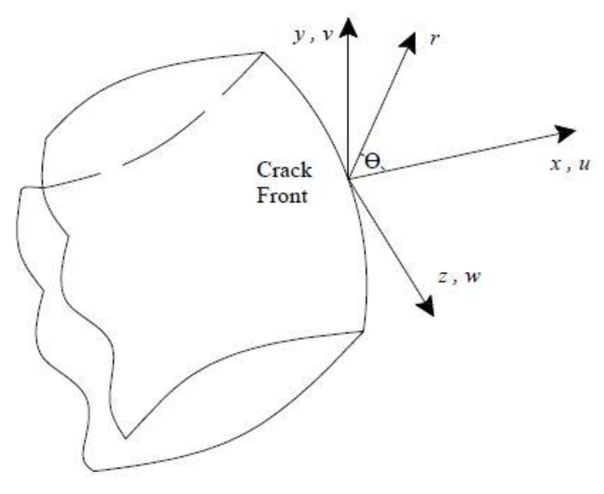
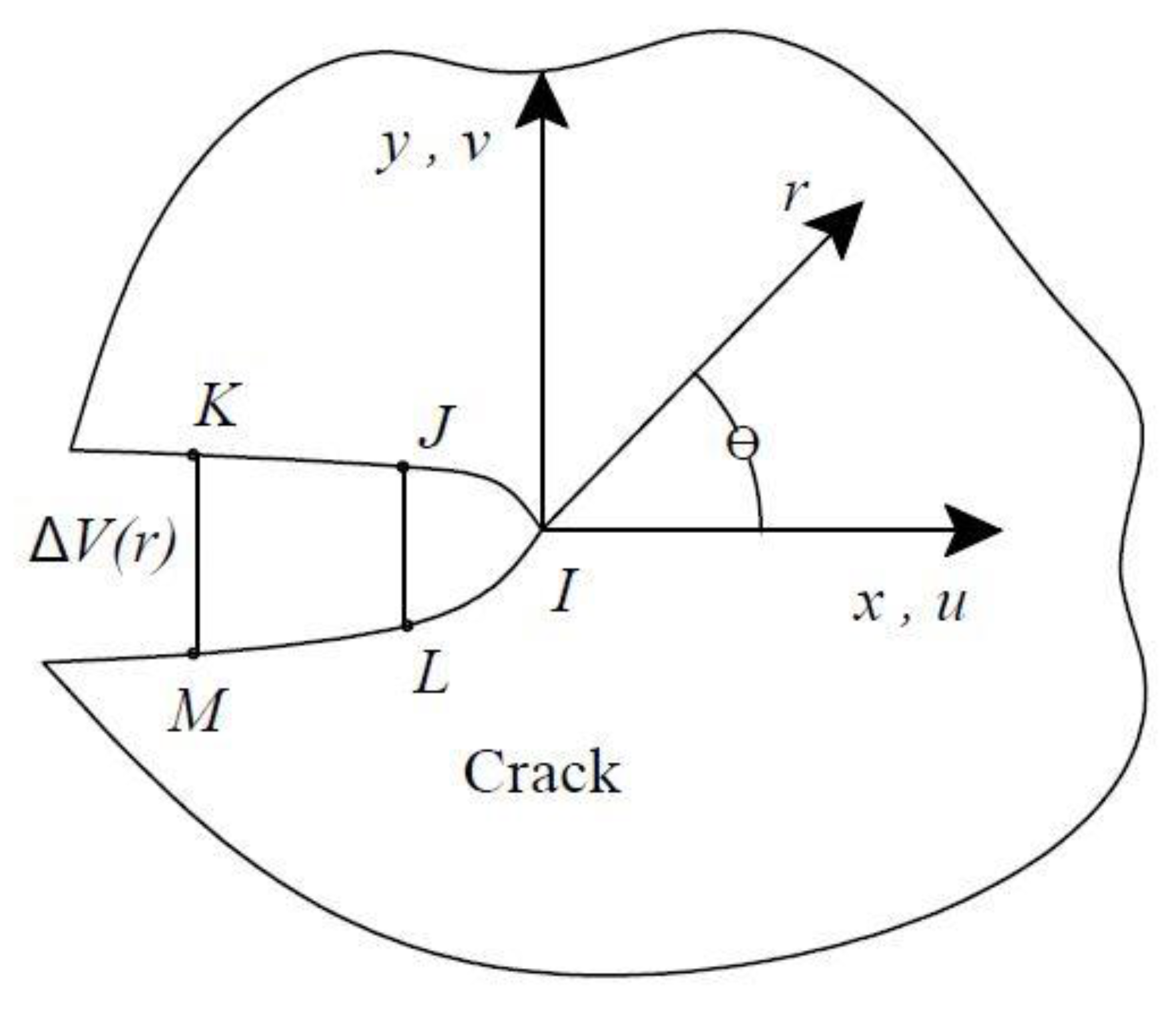
where and are the displacements in the local Cartesian coordinate system, respectively, as shown in Figure 2. and are the coordinates in the local cylindrical coordinate system, as shown in Figure 3. is the shear modulus. and are the SIFs related to deformation.
where is a term of order or higher, and the high-order term is omitted. The SIFs can be expressed as
where and are the movement distances between two crack surfaces.
As shown in Figure 3, three nodes and are located on the crack surface. If point is the coordinate origin, the displacement at node is zero. Then and can be determined using the following formula
At nodes and , let r tend to 0, then
Therefore, can be expressed as
2.3. Initiation Angle of Oblique Crack
The direction of the path between the crack initiation point and the crack tip is regarded as the observed crack initiation direction. The problem of compound fracture is highly complex, and the current research focuses on the brittle fracture, using the method of linear elastic fracture mechanics. Various brittle fracture theories have been proposed by scholars to predict the initiation angle of a compound crack, such as the maximum circumferential tensile stress theory, strain energy density factor theory, and energy release rate theory.
Based on the theory of maximum circumferential tensile stress, a crack initiates and propagates along the direction of maximum circumferential stress under I-II compound loads. Taking the crack tip as the centre, a small circle (damage core) can be drawn, and the circumferential tensile stress at each point on the circle is different. In addition, is the maximum circumferential tensile stress in a certain direction and denotes the critical value of tensile stress during crack propagation. When reaches the critical value , the crack begins to extend and propagate. When the ratio of is large, the calculation model of oblique cracks is close to be subjected to uniaxial tension. In this case, the inclination angle of the crack is large, and the numerical values of the cracking angles predicted by several theories are relatively close. However, when the ratio of is small, i.e., when the mode I component of the crack is small, the crack angles predicted by these theories are quite different. Because the prediction theories of the initiation direction of a compound crack are not mature at present, to ensure the safety in practical engineering, empirical formulas are frequently established based on the experimental data of materials.
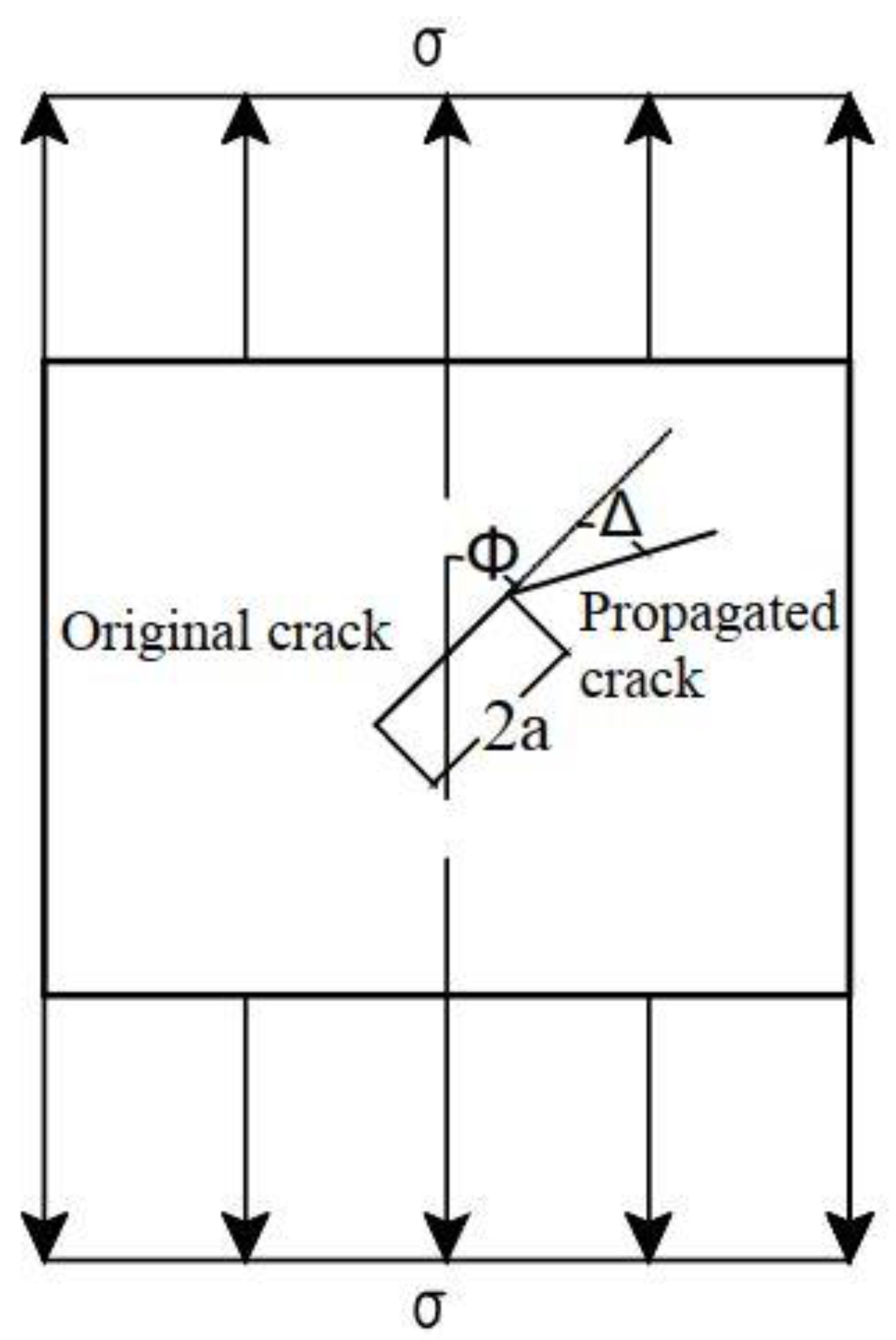
In Figure 4, the crack length is and the crack inclination angle is . It is assumed that the angle between the new crack surface and the extension line of the original crack surface after crack initiation and propagation is . When , the crack is subjected to a mode-I load. Both theoretical prediction and experimental results show that the angle between the new crack surface and the original crack surface is 0 after the crack propagates unsteadily, i.e., the crack propagates along the original crack surface. When , the crack is subjected to the combined action of mode-I and II loads, and the relationship between crack initiation angle and crack inclination angle is as follows [26]
The equation is a special case of predicting the crack initiation angle. It is an analytical formula for a flat plate with a penetrating composite crack under tension at both ends. In this paper, the formula is used to prove the feasibility of predicting crack initiation direction by finite element simulation. The maximum circumferential tensile stress theory is used to predict the initiation angle of an oblique crack. The initiation direction of a crack is along the direction of the maximum circumferential tensile stress around the crack tip, then the crack propagates unsteadily. To simulate the singularity at a crack tip, a number of parameterized modified solid elements are used. Accordingly, to predict the initiation direction of an oblique crack, it is only necessary to obtain the location of the element with the maximum circumferential tensile stress around the crack tip. Following this, the direction of the newly generated crack surface after the crack unsteadily propagates can be determined.
In the SIF calculations, the number of modified solid elements is 12 at the crack tip, and the circumference of the crack tip is divided into 12 equal parts, each with an angle of 30°. Clearly, this number of elements and accuracy are ineffective for predicting the crack initiation angle, as shown in Figure 5. Therefore, the number of singular elements at the crack tip is increased to 30 or 36, so that the crack angle can be approximately predicted to be within a range of 12° or 10°, which nearly satisfies the engineering needs. In the finite element analysis software, the stress and displacement values of the elements are obtained using the interpolation method of the adjacent nodes.
2.4. Theoretical Shape of Plastic Zone
Jing and Khraishi [27,28] derived analytical solutions for crack tip plastic zone shape using the Von Mises and Tresca yield criteria and closed-form solutions for mode II crack tip plastic zone shape. Not only do these works talk about the plastic zone shape that the current paper discusses but they also talk about criteria for the path of crack extension. Based on the expressions of stress fields near a crack tip and the calculation formulas of the principal stress in material mechanics, the principal stresses near the crack tip can be expressed as
In this study, only the outer surface of a thin-walled cylindrical shell is considered in the calculation of the plastic zone. In this case, it belongs to a plane stress state, so . To estimate the plastic zone, the von Mises yield condition is adopted, i.e.,
where represents the yield limit of the material under uniaxial tension.
Substituting Equations (16) and (17) and into Equation (20), it can be obtained:
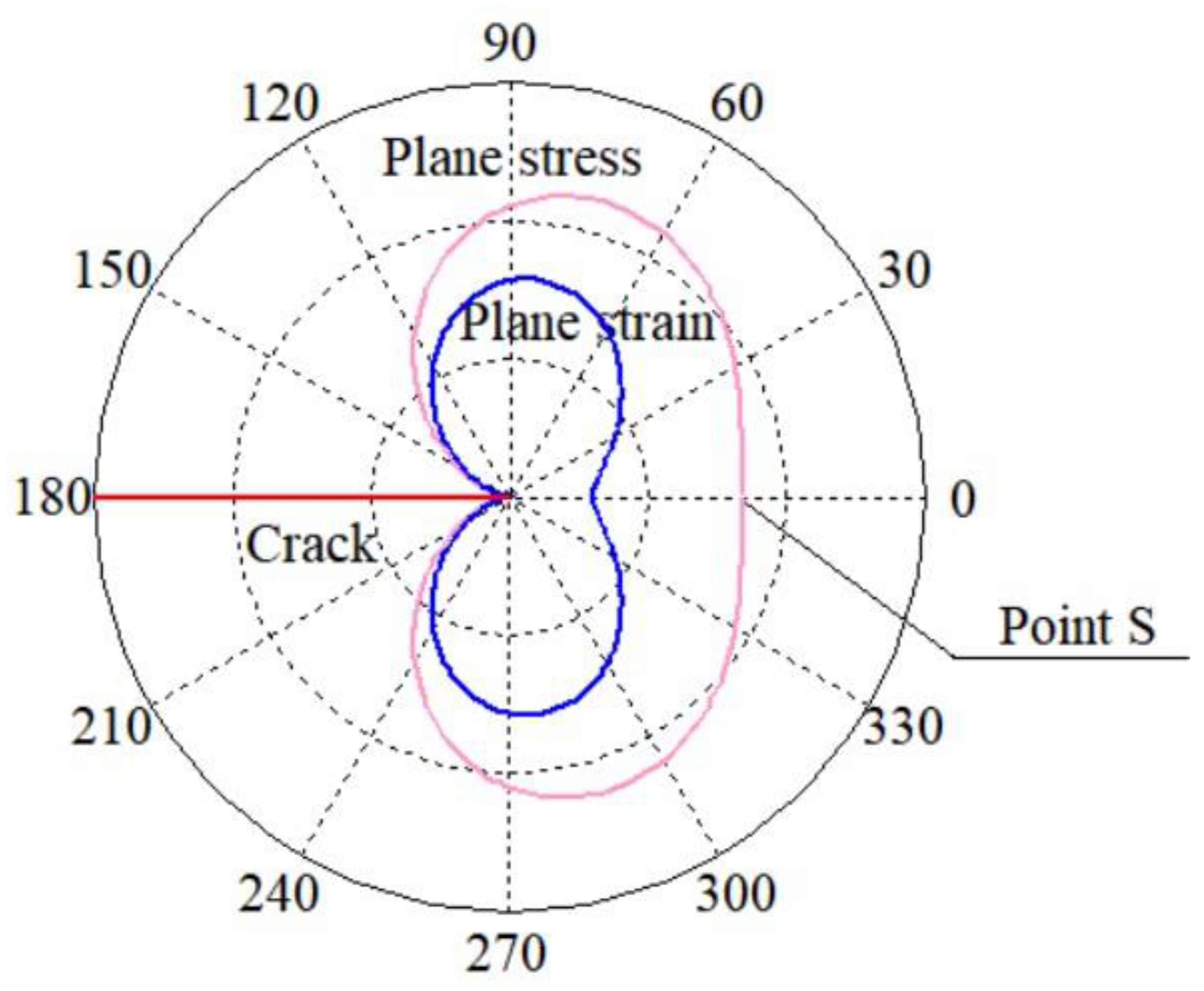
The above formulas are the curve equations in the polar coordinate system of the plastic zone near a crack tip under the state of plane stress and the state of plane strain, respectively. The shapes of the plastic zones are drawn using the Equations (21) and (22), as shown in Figure 6. When , the sizes of the plastic zone [26] on the extension line of the crack are:
3. Finite Element Models of Thin-Walled Cylindrical Shell with Cracks
3.1. Model and Structure
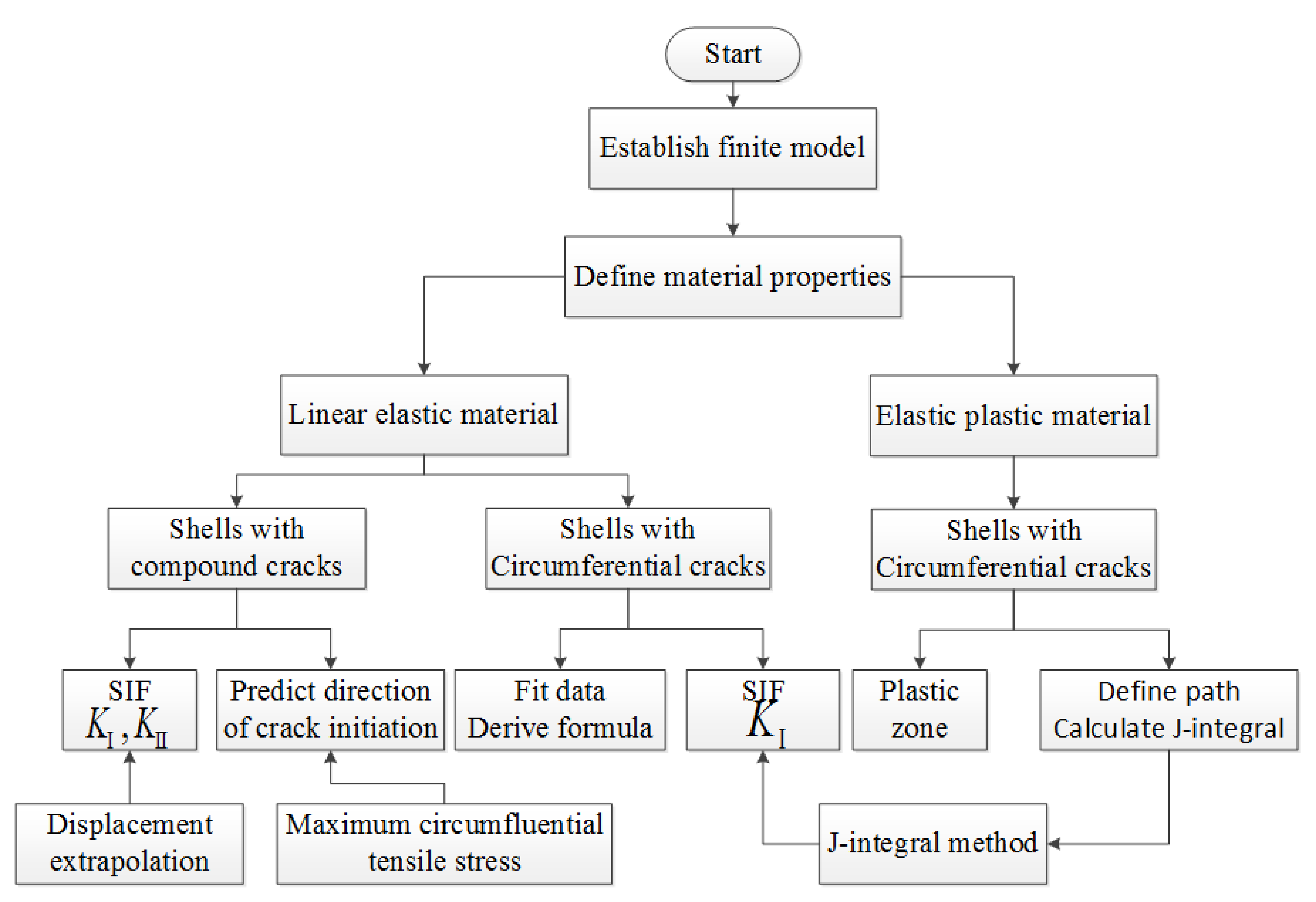
In this study, the following assumptions are made. (1) Both ends of the column are hinged. (2) The loads act in the longitudinal symmetry plane of the thin-walled column. (3) The mode-I crack is located at the edge of the tensile side of the middle section of the column, and the crack forms symmetrically at the crack section. (4) The self-weight is ignored. The entire calculation process is shown in Figure 7. The models established in this paper include: (1) The linear elastic fracture behaviour of thin-walled cylindrical shells with circumferential cracks under eccentric compression is analysed, as shown in Section 4. (2) The elastic-plastic fracture behaviour of thin-walled cylindrical shells with circumferential cracks under eccentric compression is studied, as shown in Section 5. (3) The linear elastic fracture behaviour of thin-walled cylindrical shells with oblique cracks under tension and combination of tension and bending moment is studied, respectively, as shown in Section 6.
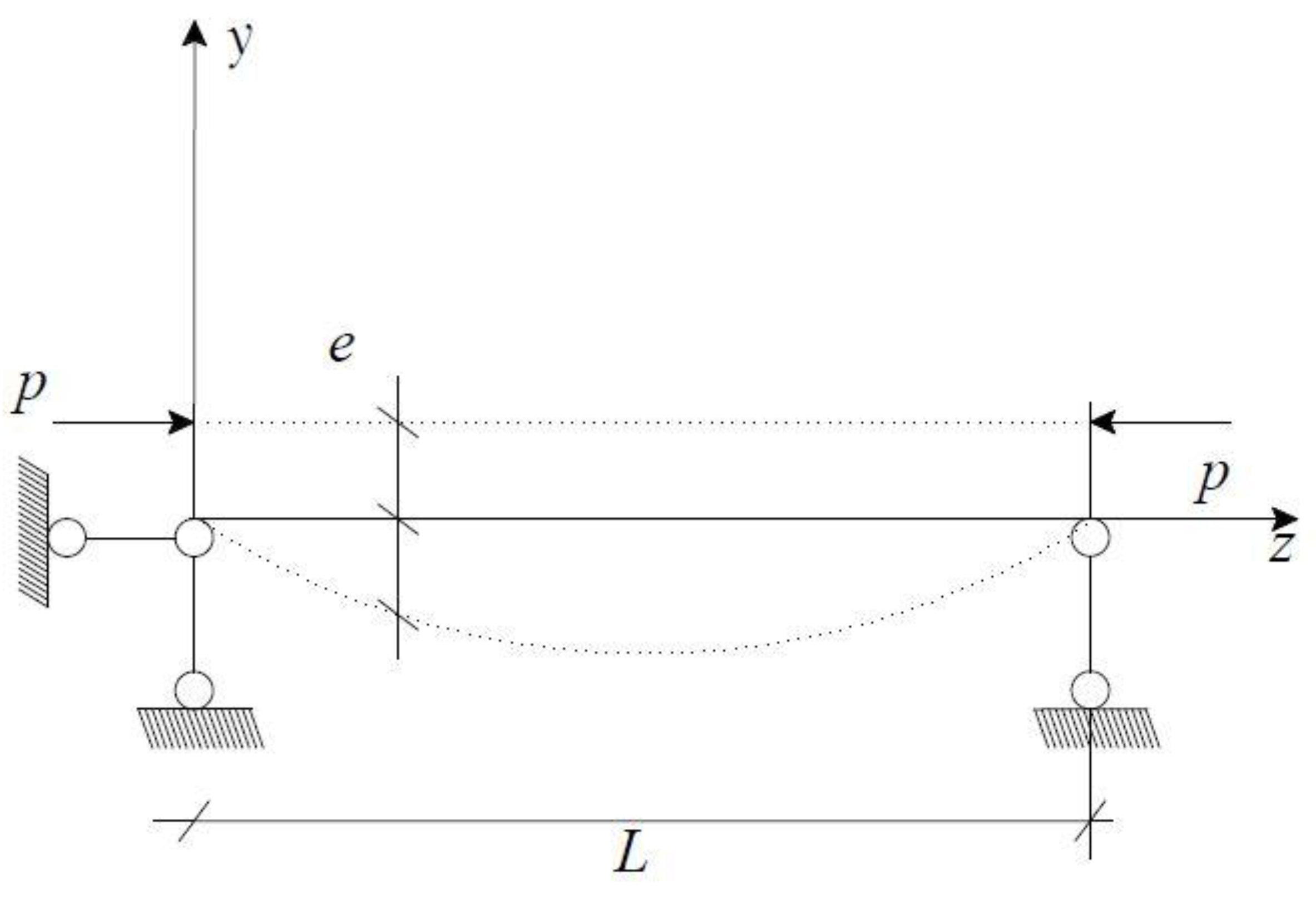
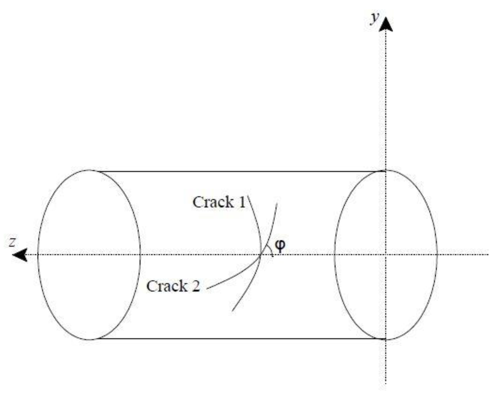
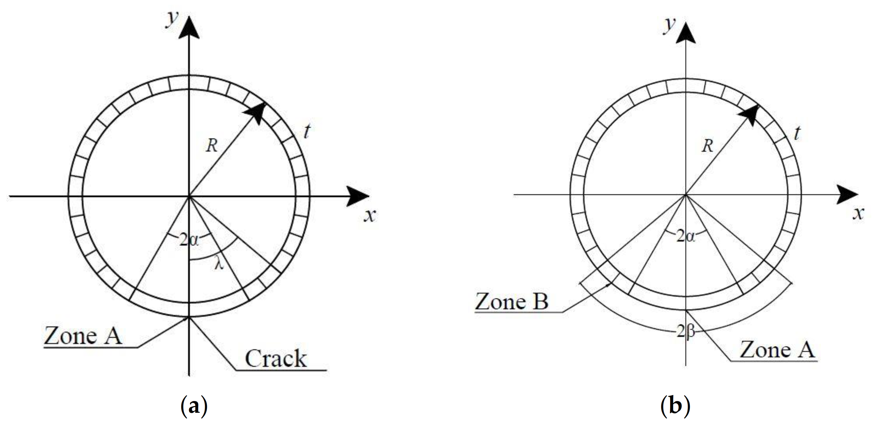
Figure 8 is a schematic diagram of the mechanical model, taking the state of eccentric compression as an example. Figure 9 is a simplified diagram of the geometric model, including a circumferential crack and a compound crack. Crack 1 represents a circumferential crack, corresponding to Section 4 and Section 5 below. Crack 2 is an oblique crack, corresponding to Section 6. Figure 10 shows the sections of thin-walled cylindrical shells with cracks, including linear elastic and elastic-plastic materials. Regions A and B represent the crack zone and the plastic zone, respectively. For linear elastic materials, the thin-walled cylindrical shell as shown in Figure 10a contains circumferential cracks, where region A represents the crack zone. For elastic-plastic materials, as shown in Figure 10b, the thin-walled cylindrical shell contains circumferential cracks, where region A represents the crack zone and region B represents the plastic zone. In this study, for thin-walled cylindrical shells with cracks, the following parameters are considered: the radius R = 0.10 m, wall thickness t = 0.01 m, length L = 5 m, elasticity modulus E = 206 GPa, and Poisson’s ratio µ = 0.3. e is the distance between the load and the axis of the section, and ε = e/R is the eccentricity.
For a circular section, is defined as the centre angle corresponding to the half length of the crack. So, the crack length is determined by changing the central angle . The value range of is 0°–45°, and the corresponding crack length . Here, the total crack length is determined as . The ratio of the crack length to its maximum crack length is , which is called as the crack length coefficient, and the value range is .
Because the sections with different inclination angles are ellipses having unequal perimeters, the length of the compound crack cannot be accurately reflected by the size of the centre angle θ corresponding to the compound crack. The crack length coefficient is introduced, which is the ratio of the true length of the crack to the half circumference of the section where the crack is located. The crack angle is the angle between the oblique crack and the coordinate z-axis.
3.2. Element Type
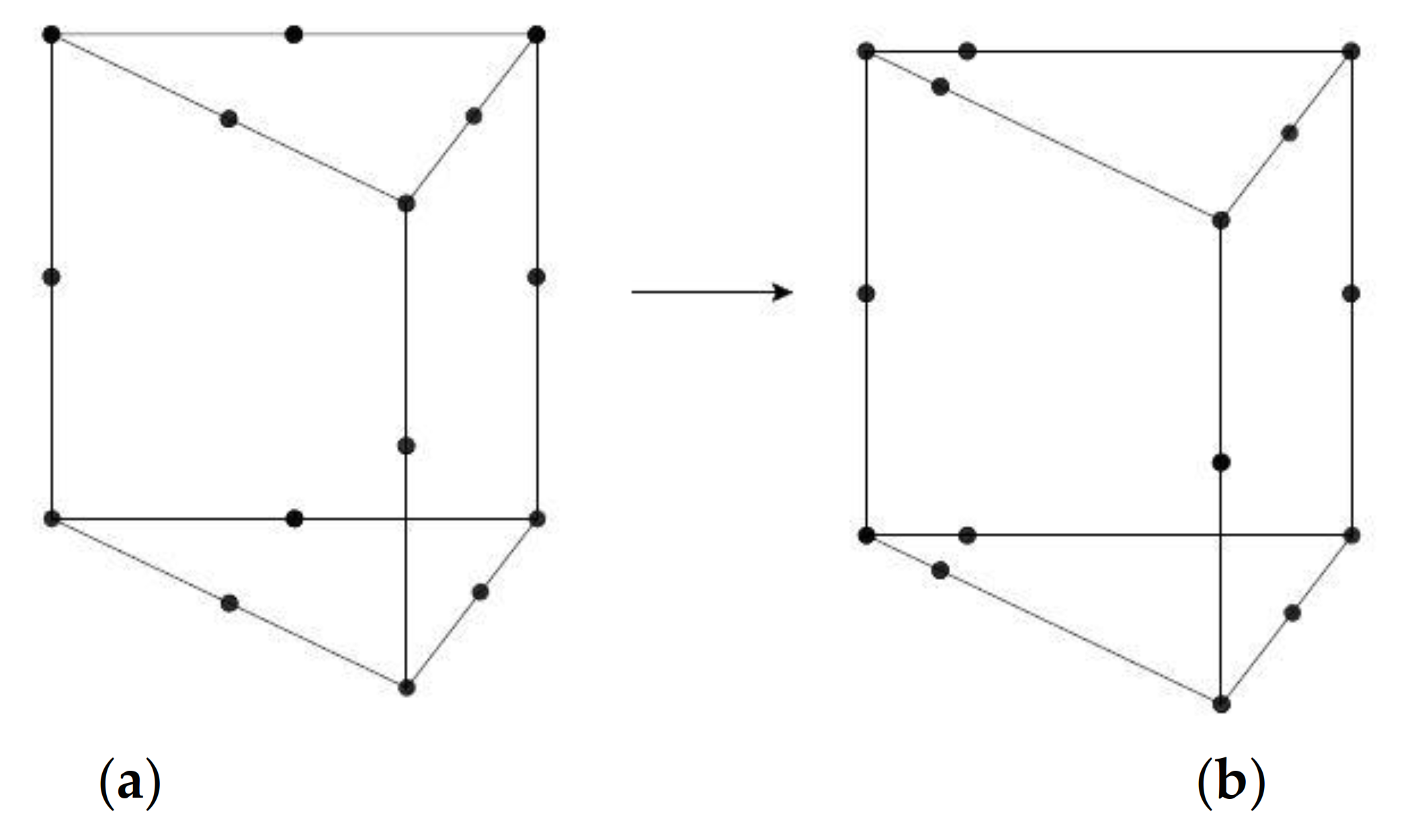
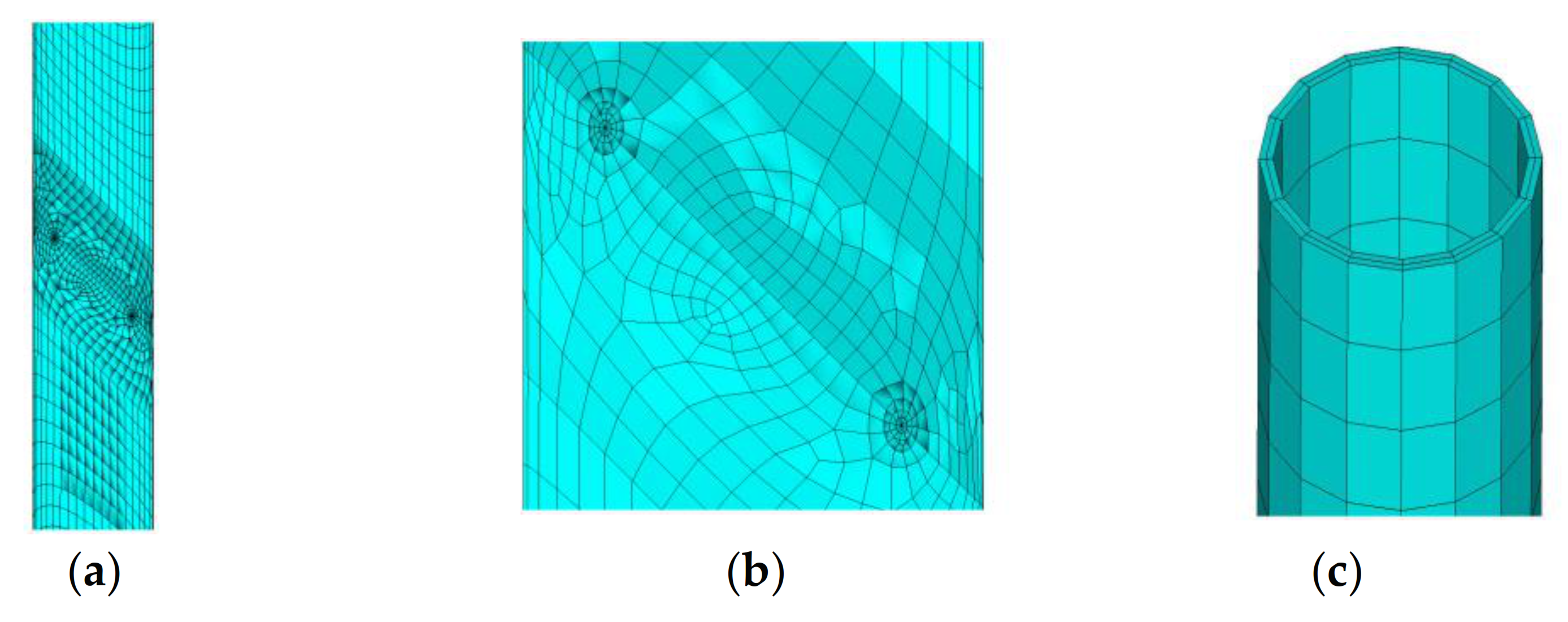
- Thin-walled cylindrical shells with circumferential cracks. Elements Solid45 and Solid95 are used to model a structure with spatial cracks. Solid95 element is used to simulate the singularity at a crack tip, and Solid45 element is used for the remaining part. SOLID45 is used for the 3-D modelling of solid structures. The element is defined by eight nodes having three degrees of freedom at each node: translations in the nodal , , and directions. The element has plasticity, creep, swelling, stress stiffening, large deflection, and large strain capabilities. SOLID95 is a higher-order version of the 3-D 8-node solid element SOLID45. It can tolerate irregular shapes without as much loss of accuracy. SOLID95 elements have compatible displacement shapes and are well suited to model curved boundaries. The element is defined by 20 nodes having three degrees of freedom per node: translations in the nodal , , and directions. The element may have any spatial orientation. SOLID95 has plasticity, creep, stress stiffening, large deflection, and large strain capabilities. Considering the symmetry of the problem, the quarter model is adopted for the analysis. As shown in Figure 11, an element can be transformed into a three-dimensional singular element by moving the middle node of the element at the crack front edge to 1/4 from the front edge. To ensure the calculation accuracy and improve the calculation speed, the number of modified singular elements is 12 when dealing with the SIF.
- Thin-walled cylindrical shell with oblique cracks. In the case of oblique cracks, the finite element model is not symmetric and a complete geometric model needs to be established. In addition to Solid45 and Solid95, Mesh200 is also required. Mesh200 element is only used for meshing and has no effect on the solution results. It can be used to divide faces and bodies in 2D and 3D spaces. Mesh200 element should contact Solid95 and Solid45 elements in a crack-affected zone and a non-affected zone, respectively. MESH200 is a “mesh-only” element, contributing nothing to the solution. MESH200 may be used in conjunction with any other ANSYS element types. After it is no longer needed, it can be deleted (cleared), or can be left in place.
- An eccentric concentrated load is equivalent to the axial compression load and the bending moment. Because the model section is a hollow section, MPC184 element is used to form a rigid beam area to apply the load at the coupling point. MPC184 comprises a general class of multipoint constraint elements that apply kinematic constraints between nodes. The elements are loosely classified here as constraint elements and joint elements. The constraint may be as simple as that of identical displacements between nodes. Constraints can also be more complicated, such as those modelling rigid parts, or those transmitting motion between flexible bodies in a particular way. In the Figure 12, the purple part is Solid45, blue part is Solid95, red part is MESH200, and green part is MPC184.
3.3. Mesh Generation and Boundary Conditions
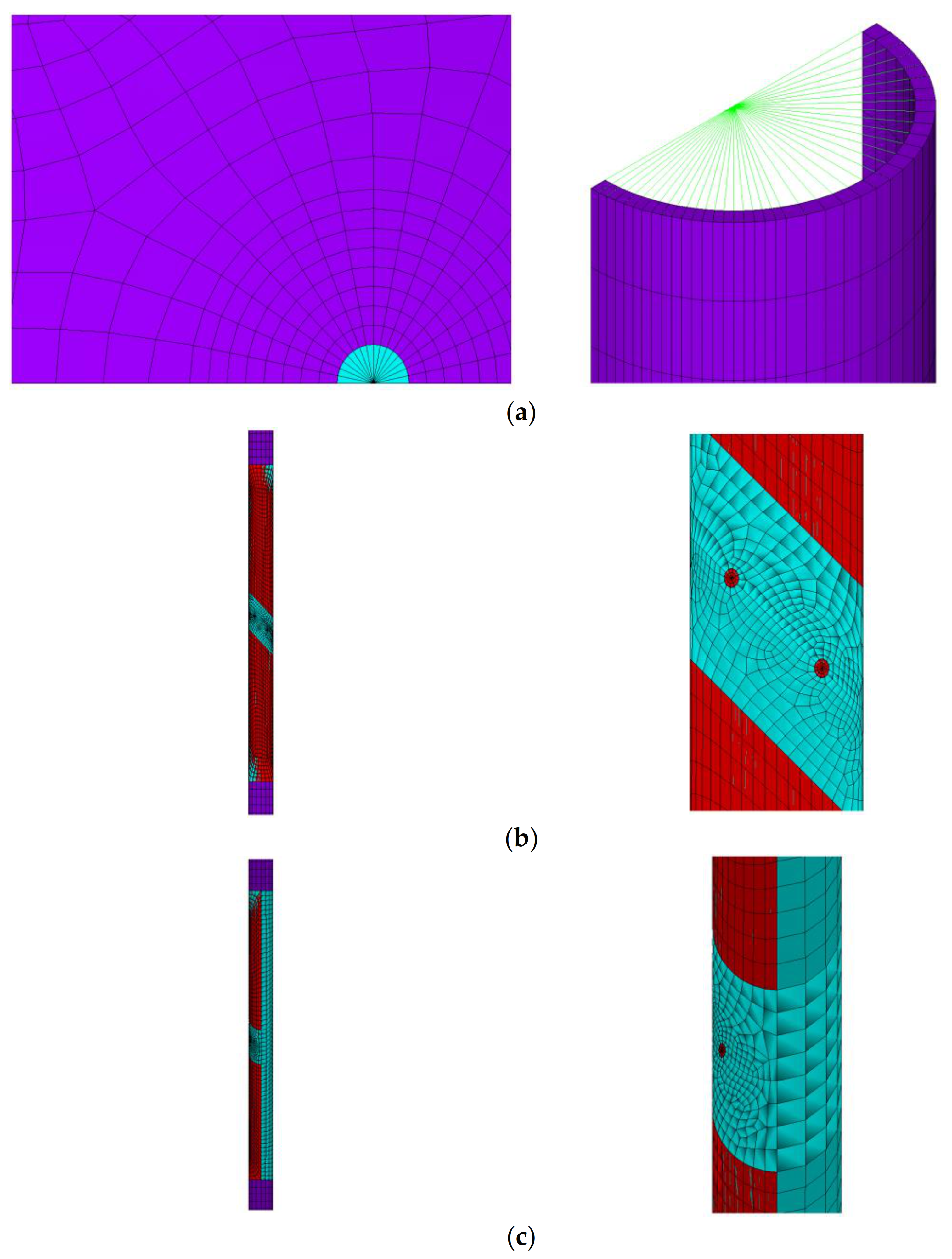
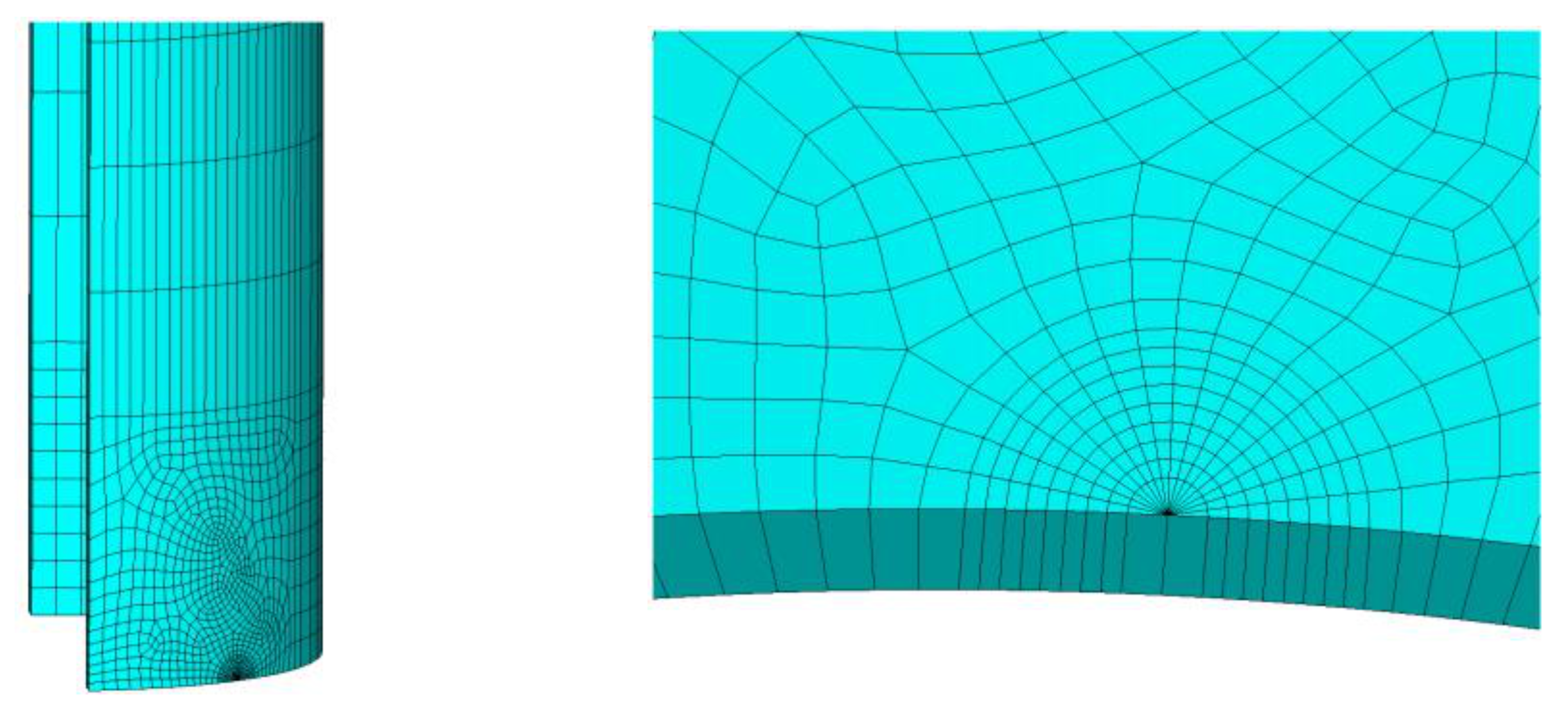
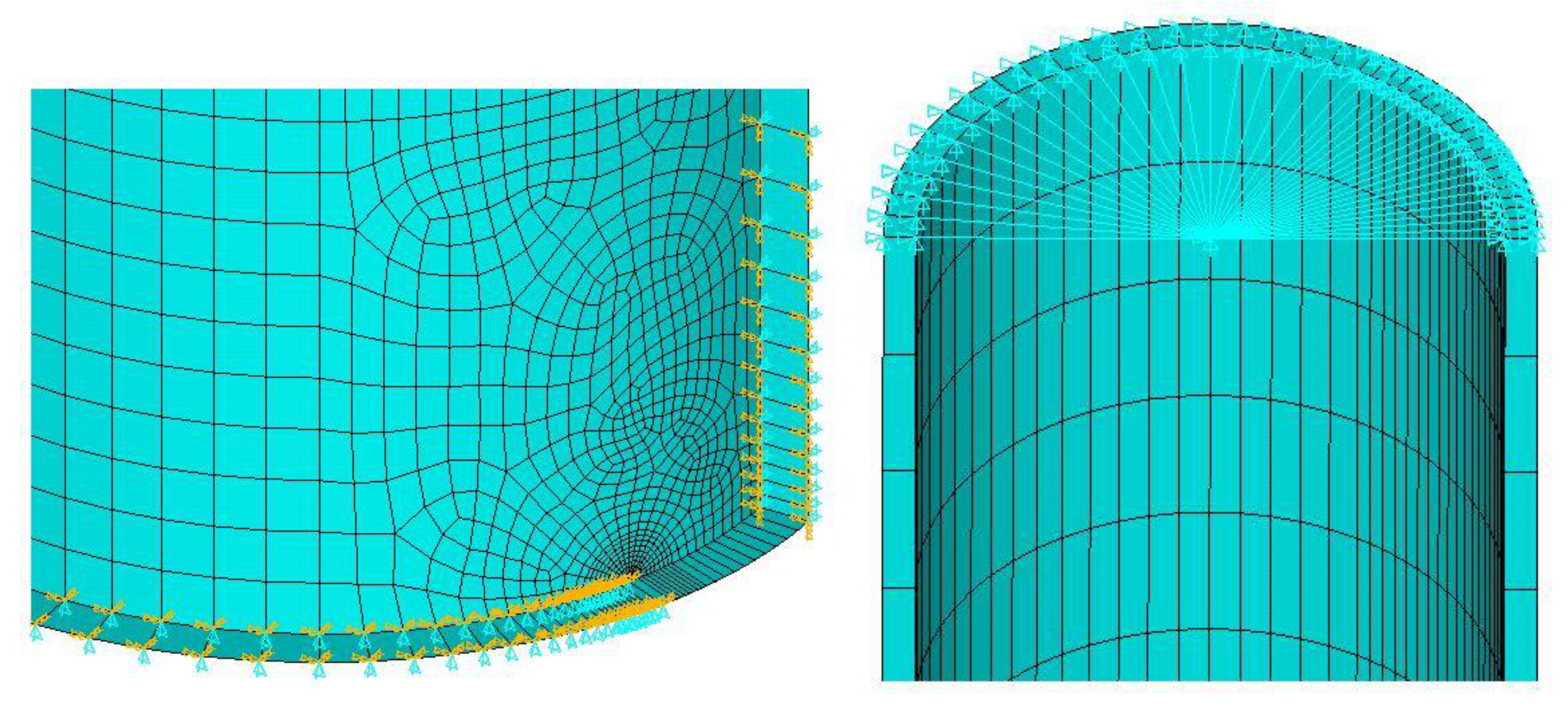
For a thin-walled cylindrical shell with a mode-I crack, the quarter model, as shown in Figure 13, is established, and symmetric constraints are applied at the boundaries of the symmetry surfaces. The symmetry surfaces and symmetry conditions are shown in the Figure 14. It can be seen that the constraint is applied from the crack tip, and the part not applied is the half crack length. There are two key points in the modelling process. The first is that the mesh near the crack tip must be fully refined when performing the relevant calculation. Because of the singular stress field and high strain gradient in the crack front, the elements at the crack front should be singular elements. The second key point is that in the determination of the size of the plastic zone at the crack tip, the accuracy of the meshing significantly affects the accuracy of the results. The length of the element closest to the crack in the model is 1/78 of the minimum crack length. Moreover, the element sizes are maintained at the same order of magnitude over a wide range around the crack tip, to better meet the accuracy requirements of the results in various yield ranges. For the quarter thin-walled cylindrical shell with circumferential cracks, the one layer of elements exists in the thickness direction.
For a thin-walled cylindrical shell with a compound crack, the most important part is the analysis of the crack tip and the crack-affected zone, and the mesh of the crack with different accuracies at different positions. The calculation accuracy of the most critical crack tip is governed by the number of singular elements, as shown in Figure 15. The larger the number, the higher the calculation accuracy. It is stipulated in ANSYS that solid elements have only three translational degrees of freedom in the and directions, but no rotational degrees of freedom. Therefore, when dealing with the right hinged support, it is necessary to limit and at the two nodes where the right section intersects the plane. Similarly, when dealing with the left hinged support, only , and are limited at the two nodes where the left end section intersects the plane. For a complete thin-walled cylindrical shell with oblique cracks, the two layers of elements exist in the thickness direction.
4. Analysis of Elastic Fracture Behaviour of Shells with Circumferential Cracks
4.1. SIF of Thin-Walled Cylindrical Shells
In fracture analysis, the J-integral method is frequently used to calculate the SIF of a crack. First, the J-integral value on a certain path is calculated; subsequently, the value of SIF is obtained using the relationship between and .
The parameters of the thin-walled column studied in this paper are as follows: the radius R = 0.10 m, wall thickness t = 0.01 m, length L = 5 m, elasticity modulus E = 206 GPa, Poisson’s ratio , and eccentricity .
Suppose the applied load , where and is the load factor, i.e., the ratio of the applied load to the basic load. The SIF data are extracted when eccentricity is , and Figure 16 shows the relationship curves of and under different loads. It can be seen that the SIF changes almost linearly with the increase in the crack length. At the same crack length, the SIF also increases with the increase in the load factor .
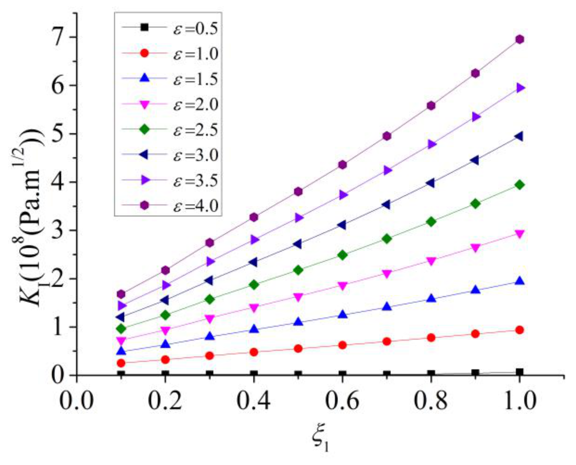
The SIF data are extracted when the load is P = 360 kN, and Figure 17 shows the relationship curves of and under different eccentricities. It can be seen that the SIF exhibits a linear variation with the increase in crack length . At the same crack length , with the increase in eccentricity , the SIF significantly increases. Particularly, when the eccentricity is small, the SIF changes little with the increase in the crack length . The crack opens less and develops less remarkably.
4.2. Data Fitting of SIF
For the cylindrical shell with a transverse crack subjected to a uniform tensile load in reference [29], the SIF of the tensile mode is as follows.
where the parameters and variables involved are described in reference [29].
In this paper, the tensile stress of a crack section gradually decreases along the circumference to the compression zone, and the specific expression is as follows:
where is the concentrated load, denotes the cross-section area, and represents the moment of inertia of the circular cross-section.
The equivalent calculation is as follows
For the model used in this paper, the formula in reference [29] is transformed into
where and are constants; therefore, can be rewritten as in this paper.
Linear regression and data fitting are conducted, and the corresponding SIFs are
5. Elastic-Plastic Fracture Mechanical Behaviour of Shells with Circumferential Cracks
5.1. Plastic Zone in Front of Crack
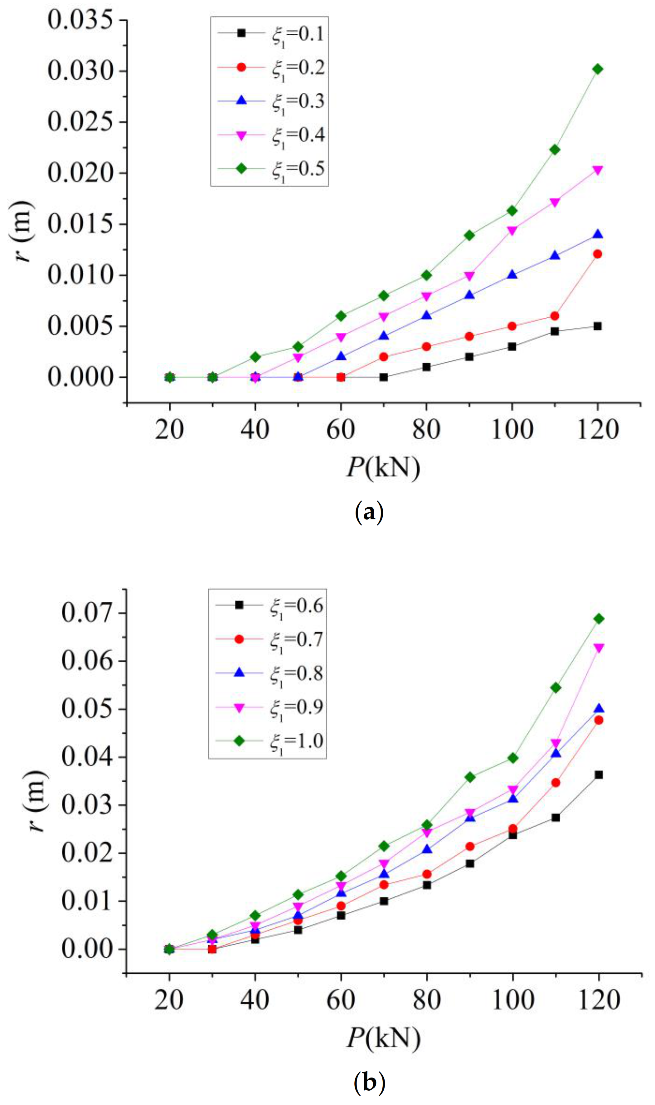
In ANSYS modelling, the mesh fineness at a crack tip affects the accuracy of the size of the plastic zone. It cannot satisfy the condition that the plastic zone is less than the minimum element length; therefore the extracted data can meet the requirements within a certain range. Moreover, when yielding in a small range, only few nodes can be selected in the plastic zone, and the curve formed by these nodes is not sufficiently smooth. After conducting the data fitting, the resulting curve only yields the approximate range of the plastic zone, with a small error. The line with the angle of represents the direction of the crack propagation, and the crack is located on the line with the angle of . represents the distance from the point S on the boundary of the plastic zone to the crack tip, as shown in Figure 6. Because the size of the plastic zone is remarkably affected by external loads, their relationship should be first considered. As shown in Figure 18, when the eccentricity is , the plastic zone at the crack tip changes with external load .
It can be seen that the size of the plastic zone on the crack extension line increases with the increase in the load. Moreover, the longer the crack is, the faster the size of plastic zone increases. When the load increases to a certain value, the growth curve of the plastic zone size is almost perpendicular to the abscissa. The reason is that under the eccentric pressure, the side relative to the crack has already entered the yielding state. With the increase in the load, both the tension plastic and compression plastic zones in the crack front increase at a rapid rate until the full yield is achieved.
5.2. J-Integral of Elastic-Plastic Fracture
The J-integral can be used not only to solve the problems of linear elastic fracture mechanics, but also to solve the problems of elastic-plastic fracture. And it is suitable for both small-scale yield and large-scale yields. The model used is consistent with the above model for calculating the size of the plastic zone. In the post-processing stage, the contour integral method is used to calculate the J-integral, and attention is paid to the selection of the integral path. 16 integral paths with different lengths are selected around the crack tip in a certain range, and the arithmetic mean value is taken as the calculation result.
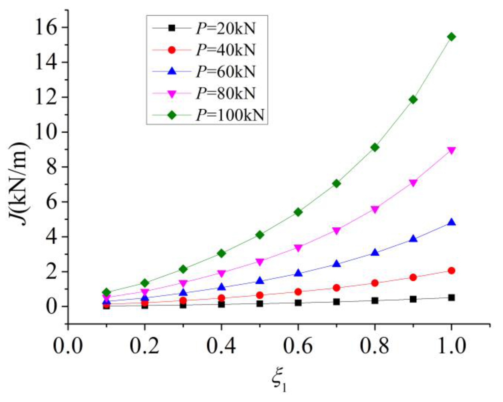
The calculated values of the J-integral with the eccentricity are extracted. The J-integral versus crack length curves under different loads are shown in Figure 19. It can be seen that when the load is relatively small, the value of the J-integral increases gradually with the increase in the crack length. However, when the load is large, even if the crack length increases only slightly, the value of the J-integral increases significantly.
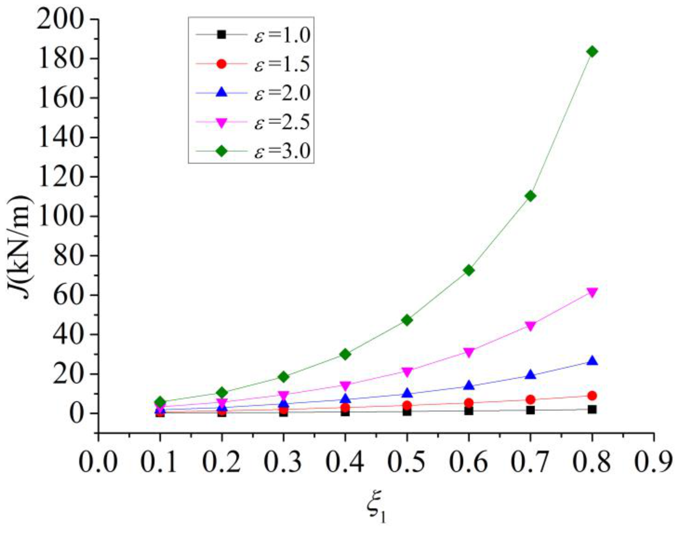
The calculated values of the J-integral are extracted when the load is P = 100 kN. Figure 20 shows the curves relating the value of the J-integral and the crack length under different eccentricities. When the eccentricity is relatively small, the value of the J-integral increases gradually with the increase in the crack length. However, when the eccentricity is large, the value of the J-integral increases significantly even if the crack length only increases slightly. This is very similar to the trend of the effect of the load on the J-integral. The reason is that the stress at a crack tip is determined by both the load and eccentricity; therefore, both effects on the J-integral are fundamentally the same.
6. Fracture Behaviour of Thin-Walled Cylindrical Shells with Oblique Cracks
6.1. Distribution of Cracks on Members Subjected to Tension at Both Ends
When the angle of an oblique crack is between 0° and 90°, certain stresses cause mode-I and mode-II cracks in the stress field at the crack tip. The oblique crack simultaneously subjected to the stresses of these two modes of cracks is called as I-II compound crack. When the inclination angle of the crack is and the external load is the normal stress perpendicular to the crack plane, the relative displacement of the crack surface is perpendicular to the crack plane. Therefore, the crack in this case can be abstractly simplified as a mode-I crack.
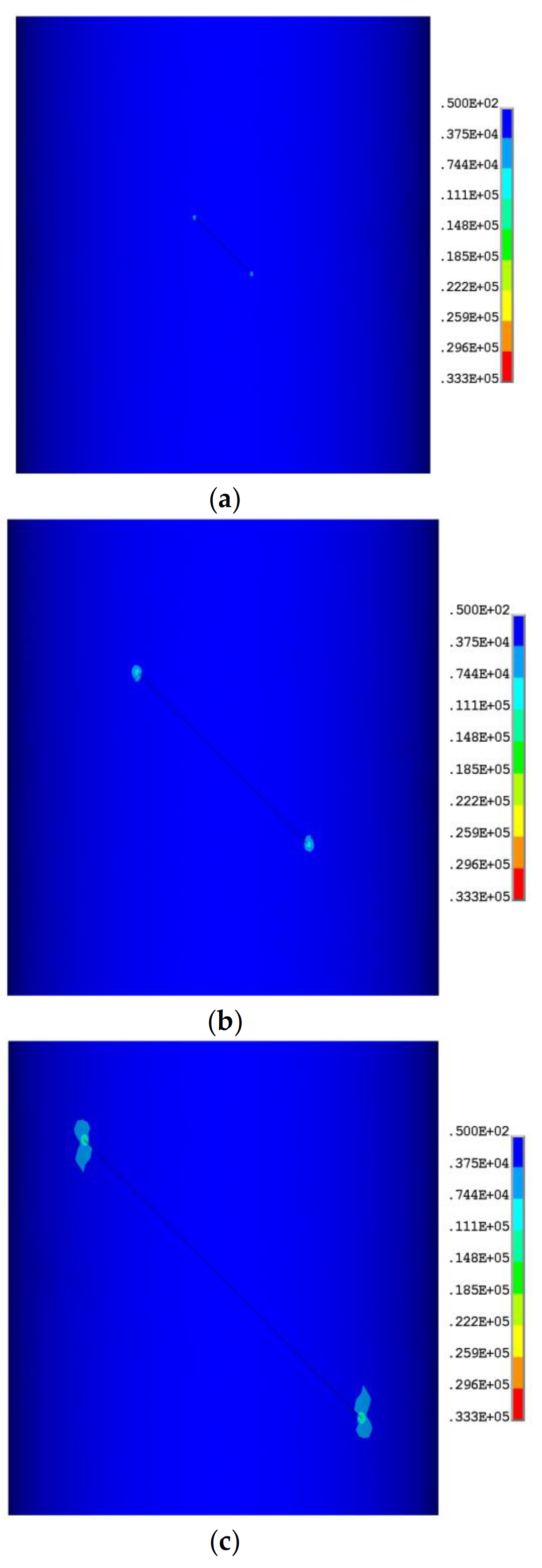
Taking the inclination angle and tension σ = 1200 Pa as an example, Figure 21 shows the distributions of different crack lengths on the components. The colour scale represents Von Mises Stress. The load form at both ends is tension. The aim is comparing stress fields for different crack length coefficients.
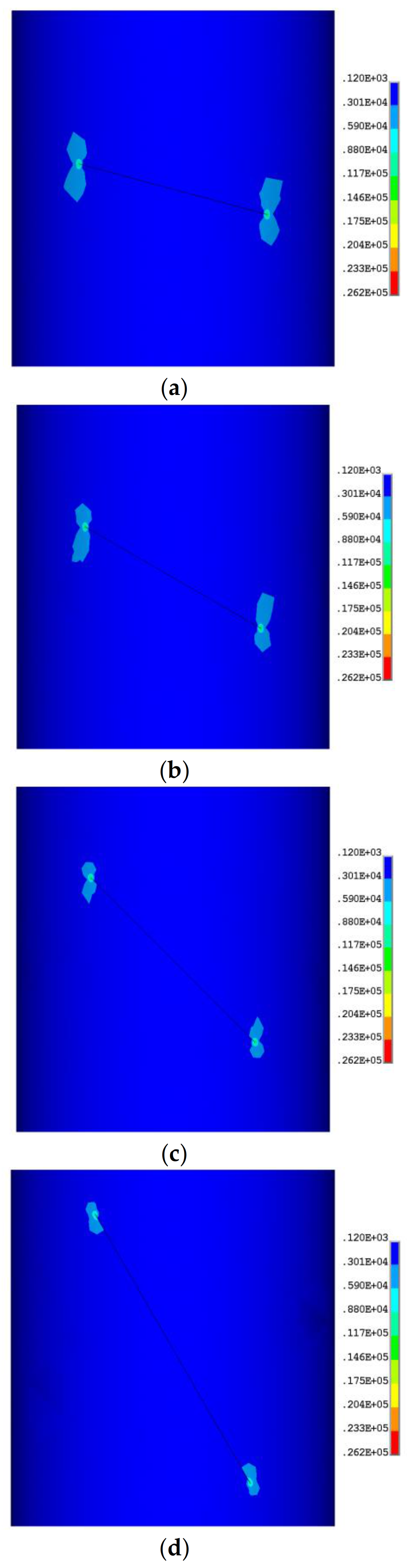
Taking the inclination angles and tension σ = 1200 Pa, and relative crack length coefficient as examples. Figure 22 shows the distributions of the cracks with different inclination angles on the components. The colour scale represents Von Mises Stress. The aim is comparing stress fields for different oblique angles.
It can be seen from Figure 21 that with the increase in crack length, the stress near the crack tip increases gradually, and the influence range of the crack also gradually expands. It can be seen from Figure 22 that with the increase in crack inclination angle, the stress near the crack tip does not change significantly, and the influence range of the crack is always near the crack tip.
6.2. Relationship between SIF and Crack Length Subjected to Tension
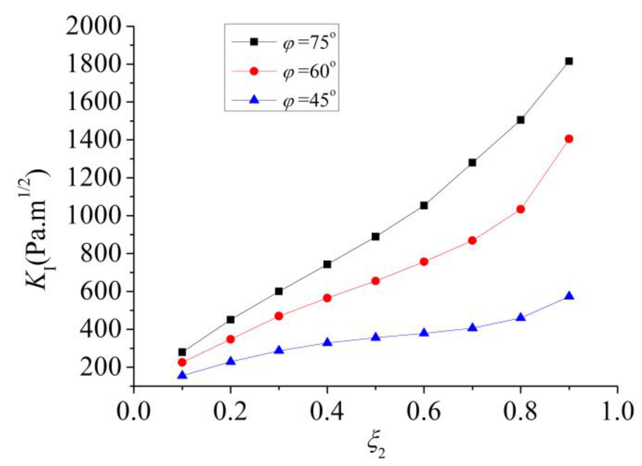
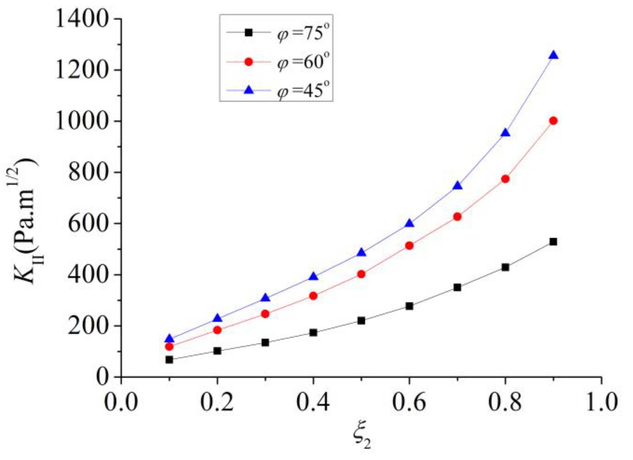
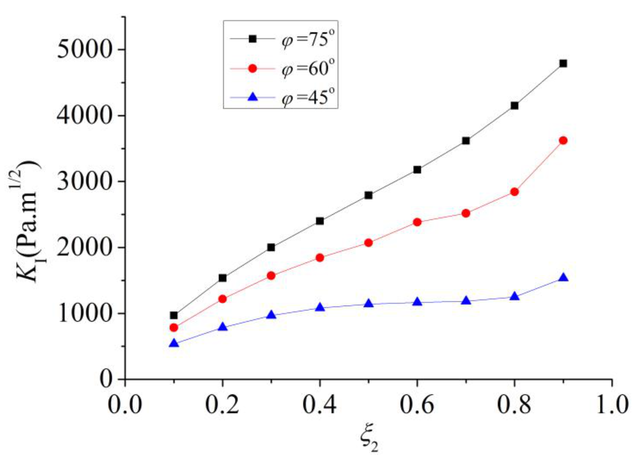
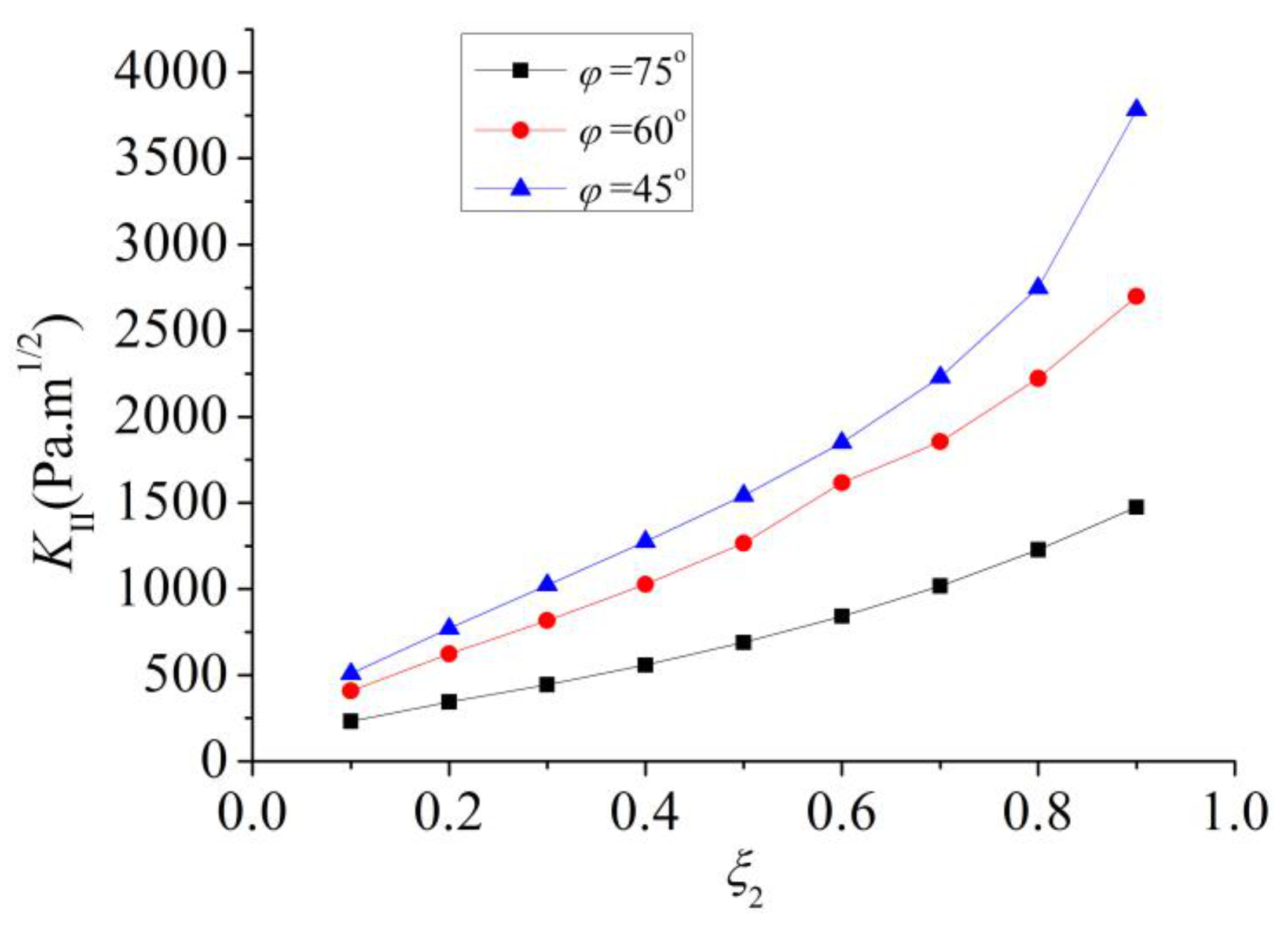
The two ends of the components are subjected to tensile stress σ = 1200 Pa. The calculated values of SIFs and using the displacement extrapolation method when the crack length changes under the different crack inclination angles are shown in Figure 23 and Figure 24, respectively.
As can be seen from the figures, when the inclination angle of the oblique crack is large, the corresponding SIF is large and is small, which suggests that the crack tends to be only affected by the mode-I load. In addition, at the same inclination angle of the crack, the calculated values of and increase with the increase in the crack length, and the increasing trend becomes more rapid. This means that with the increase in the crack length, the possibility of crack instability and propagation increases, and the component is increasingly prone to undergo failure.
6.3. Relationship between SIF and Crack Length Subjected to Tension and Bending Moment
Under the actual engineering conditions, components are rarely subjected to a single tensile action, and the external loads are typically very complex. To truly reflect the stress state of a thin-walled component in the actual engineering, the external load action form is changed in this section. Both ends are subjected to uniform tensile stress σ = 1200 Pa and bending moment M = 0.8 N m. Under the action of the bending moment, the normal stress generated by bending moment is not a constant value but varies with the change in the inclination angle.
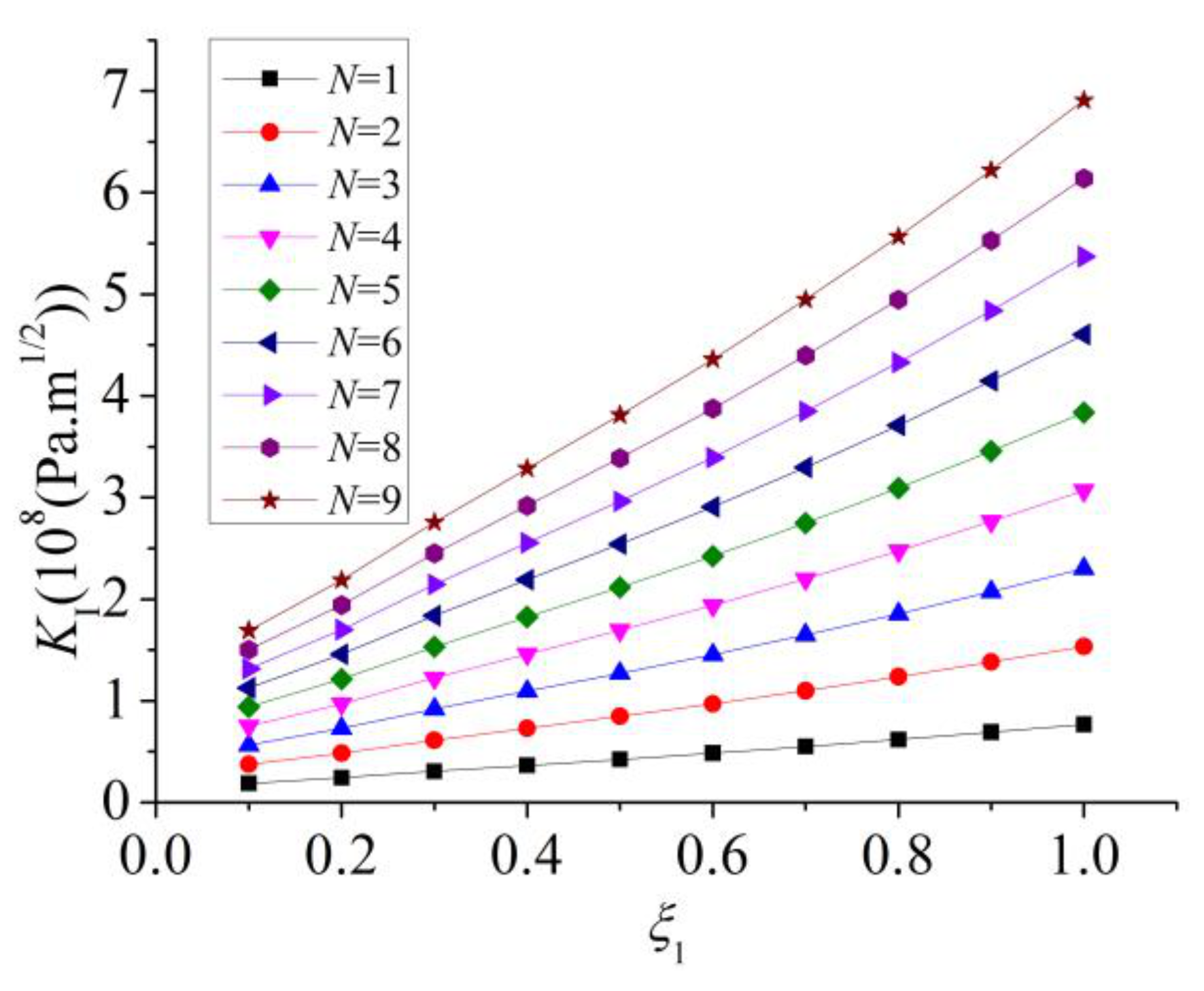
Under the combined action of tension and bending moment, to determine the effect of the bending moment on the SIF of the oblique crack, the SIFs and when the crack length changes under different crack inclination angles are calculated. The results are shown in Figure 25 and Figure 26, respectively.
It can be seen from the two graphs of SIFs and that the SIFs under the combination of tension and bending moment uniformly increase compared with those under single tension. This is because bending moment also produces a normal stress on the section. In addition, the change trends of the SIFs with the crack length and inclination angle under the combination of tension and bending are similar to those under a tensile load.
6.4. Prediction of Crack Initiation Angle of Shells Subjected to Tension
The main characteristic of the unstable propagation of a compound crack is that the crack does not propagate along the original crack direction. This feature is a problem that is encountered when studying the fracture of a compound crack. An oblique crack on a thin-walled cylindrical shell subjected to tension or combination of tension and bending moment is a type of I-II compound crack.
By increasing the number of singular elements at the crack tip, the prediction accuracy of the crack initiation angle is improved. The other difference is mainly in the post-processing stage after the calculation completion. The output coordinate system of the result is activated as the cylindrical coordinate system. In ANSYS software, is the circumferential tensile stress mentioned above. Other , , etc. can be found in the ANSYS help document. The node stress values of all singular elements are output, and the maximum stress value of the element is obtained from the output values. It is the maximum value of in polar coordinates. Furthermore, the crack initiation direction can be predicted.
Both ends of the thin-walled cylindrical shell are subjected to a tensile stress σ = 1200 Pa. The crack inclination angle is , and the relative length of the crack is After the node stress values of the 36 singular elements at the crack tip are output, the element with the maximum is found, as listed in Table 1.
In the ANSYS post-processing, the element number of the singular element with the maximum circumferential tensile stress at the crack tip and the stress value of each node are given. The node numbers with the maximum stress value are 1 and 1237, and these two nodes are the corner points of the singular element after transformation. To determine the specific direction of a new crack, it is necessary that the stress values of other nodes are also the maximum value. Therefore, based on the maximum circumferential tensile stress theory, the connecting line of the two nodes is the location of the propagated crack, and the angle between the propagated crack and the original crack is the crack initiation angle . Thus, for the above example, the predicted crack initiation angle can be obtained, and the crack inclination angle can be obtained by substituting into Equation (15). The predicted value is consistent with the theoretical value. Although the number of singular elements at the crack tip limits the accuracy of the finite element analysis results, there is a certain error between the predicted values and theoretical values under other conditions. However, the error is still within the permissible range. This method of predicting the crack initiation angles using finite element software is accurate to a certain extent.
For the same inclination angle and different crack lengths, the above calculations are also conducted. It is found that the crack initiation angle does not change significantly with the change in crack length, however, the change in crack length significantly affects the calculated values of the SIF. These results are consistent with the fact that the formula of crack initiation angle is independent of the SIF.
The results of the crack initiation angle subjected to tension for various inclination angles are summarised in Table 2 ().
6.5. Prediction of Crack Initiation Angle of Shells Subjected to Tension and Bending Moment
On the inclined sections with different inclination angles, the normal stress caused by the bending moment also varies with the change in the inclination angle of the crack. The normal stress is not uniformly distributed on the entire section subjected to the combined action of tension and bending moment. The normal stress of the cross section will affect the SIF, and the crack initiation angle predicted based on the maximum circumferential tensile stress theory will also change.
The calculation results of the crack initiation angle with the change in the crack length when the crack inclination angles are 15°, 30° and 45° are listed in Table 3, Table 4 and Table 5.
It is found that with the increase in the crack length, the crack initiation angle calculated using finite element method does not change significantly and fluctuates in a range close to the theoretical value. Therefore, it can be concluded that although the stress state of the section varies with the change in the crack length, the initiation direction of the crack is only related to its original inclination angle. That is, as long as the compound degree of the crack is determined, the crack initiation angle can also be determined.
7. Conclusions
In this paper, based on the fracture and elastoplastic theories, the SIFs, crack initiation angles, plastic zones and J-integrals of thin-walled cylindrical shells with different cracks are investigated. The main conclusions are as follows:
- Regarding the linear elastic constitutive relation, the SIFs of eccentrically compressed thin-walled shells with cracks are positively correlated with the load, crack length and eccentricity. The relationship between the SIF and the crack length is obtained by data fitting, which provides a reference for studying the cracking of thin-walled cylindrical shells with cracks.
- Regarding the elastic-plastic constitutive relation, the size of the plastic zone boundary increases with the increase in load and crack length. The entire process from small-scale yield to large-scale yield is analysed. The J-integral values are calculated for different eccentricities and loads, and their influence relations are obtained. The value of the J-integral increases with the increase in the crack length. Because the stress at the crack tip is determined by both load and eccentricity, the effects of both parameters on J-integral are basically the same.
- On the basis of previous research on compound cracks on semi-infinite plates, the change rules of the SIFs of cylindrical shells are studied. It is concluded that the change rule of the SIFs of oblique cracks on cylindrical thin-walled shells is nearly consistent with the change in the I-II compound cracks on infinite plates.
- The crack initiation angle can be obtained more accurately by increasing the number of singular elements at the crack tip and rotating the output coordinates of the results. An error is caused by the limited calculation accuracy resulting from the limitation of the number of singular elements at the crack tip. Owing to the harsh conditions of the compound crack fracture test, this method can be regarded as a mutual verification method with the test results for brittle materials with compound cracks.
Author Contributions
Data curation, F.Y.; formal analysis, F.Y. and Z.W.; methodology, F.Y.; writing—review and editing, F.Y. and Z.W. Both authors have read and agreed to the published version of the manuscript.
Funding
This research was funded by the National Natural Science Foundation of China, grant number: 51278420.
Data Availability Statement
All raw data supporting the conclusion of this paper are provided by the authors.
Acknowledgments
The authors gratefully acknowledge the support of the National Natural Science Foundation of China by Grant No. 51278420.
Conflicts of Interest
The authors declare no conflict of interest.
References
- Atamturktur, S.; Li, T.; Ramage, M.H.; Farajpour, I. Load carrying capacity assessment of a scaled masonry dome: Simulations validated with non-destructive and destructive measurements. Constr. Build. Mater. 2012, 34, 418–429. [Google Scholar] [CrossRef]
- Anderson, T.L. Fracture Mechanics: Fundamentals and Applications, 4th ed.; CRC Press: Boca Raton, FL, USA, 2017. [Google Scholar]
- Hu, S.Y.; Xie, Y.J. Stress intensity factor of angular crack in double slot circular section pipe. Chin. J. Comput. Mech. 2020, 37, 424–430. [Google Scholar]
- Xie, Y.J.; Wang, X.H. Application of G*-integral on cracked structural beams. J. Constr. Steel Res. 2004, 60, 1271–1290. [Google Scholar] [CrossRef]
- Xie, Y.J.; Wang, X.H. Stress intensity factors for cracked triangular cross-section thin-walled tubes. Fatigue Fract. Eng. Mater. Struct. 2004, 27, 1109–1117. [Google Scholar] [CrossRef]
- Xie, Y.J.; Wang, X.H.; Wang, Y.Y. Stress intensity factors for cracked homogeneous and composite multi-channel beams. Int. J. Solids Struct. 2007, 44, 4830–4844. [Google Scholar] [CrossRef] [Green Version]
- Bazant, Z.P. Justification and improvement of Kienzler and Herrmann’s estimate of stress intensity factors of cracked beam. Eng. Fract. Mech. 1990, 36, 523–525. [Google Scholar] [CrossRef]
- Dunn, M.L.; Suwito, W.; Hunter, B. Stress intensity factors for cracked I-beams. Eng. Fract. Mech. 1997, 57, 609–615. [Google Scholar] [CrossRef]
- Xing, C.; Wang, Y.X.; Waisman, H. Fracture analysis of cracked thin-walled structures using a high-order XFEM and Irwin’s integral. Comput. Struct. 2019, 212, 1–19. [Google Scholar] [CrossRef]
- Atluri, S.N. Path-independent integrals in finite elasticity and inelasticity, with body forces, inertia, and arbitrary crack-face conditions. Eng. Fract. Mech. 1982, 16, 341–364. [Google Scholar] [CrossRef]
- Blackburn, W.S. Path independent integrals to predict onset of crack instability in an elastic plastic material. Int. J. Fract. Mech. 1972, 8, 343–346. [Google Scholar] [CrossRef]
- Seshadri, R.; Marriott, D.L. On relating the reference stress, limit load and the ASME stress classification concepts. Int. J. Press. Vessel. Pip. 1993, 56, 387–408. [Google Scholar] [CrossRef]
- Sucharda, O. Identification of Fracture Mechanic Properties of Concrete and Analysis of Shear Capacity of Reinforced Concrete Beams without Transverse Reinforcement. Materials 2020, 13, 2788. [Google Scholar] [CrossRef]
- Lei, Z.; Rougier, E.; Knight, E.; Zang, M.; Munjiza, A. Impact Fracture and Fragmentation of Glass via the 3D Combined Finite-Discrete Element Method. Appl. Sci. 2021, 11, 2484. [Google Scholar] [CrossRef]
- Jahromi, B.H.; Vaziri, A. Instability of cylindrical shells with single and multiple cracks under axial compression. Thin-Walled Struct. 2012, 54, 35–43. [Google Scholar] [CrossRef]
- Dyshel, M.S. Stability of a cracked cylindrical shell in tension. Sov. Appl. Mech. 1989, 25, 542–548. [Google Scholar] [CrossRef]
- Estekanchi, H.E.; Vafai, A. On the buckling of cylindrical shells with through cracks under axial load. Thin-Walled Struct. 1999, 35, 255–274. [Google Scholar] [CrossRef]
- Zhou, L.; Huang, Y. The elastic deflection and ultimate bearing capacity of cracked eccentric thin-walled columns. Struct. Eng. Mech. 2005, 19, 401–411. [Google Scholar] [CrossRef]
- Zhou, L.; Huang, Y. Crack effect on the elastic buckling behavior of axially and eccentrically loaded columns. Struct. Eng. Mech. 2006, 22, 169–184. [Google Scholar] [CrossRef]
- Chakherlou, T.N.; Mirzajanzadeh, M.; Vogwell, J.; Abazadeh, B. Investigation of the fatigue life and crack growth in torque tightened bolted joints. Aerosp. Sci. Technol. 2011, 15, 304–313. [Google Scholar] [CrossRef]
- Gao, H.J.; Herrmann, G. On estimates of stress intensity factors for cracked beams and pipes. Eng. Fract. Mech. 1992, 41, 695–706. [Google Scholar] [CrossRef]
- Moës, N.; Belytschko, T. Extended finite element method for cohesive crack growth. Eng. Fract. Mech. 2002, 69, 813–833. [Google Scholar] [CrossRef] [Green Version]
- Sukumar, N.; Prévost, J.H. Modeling quasi-static crack growth with the extended finite element method Part I: Computer implementation. Int. J. Solids Struct. 2003, 40, 7513–7537. [Google Scholar] [CrossRef]
- Khan, S.M.A.; Khraisheh, M.K. Analysis of mixed mode crack initiation angles under various loading conditions. Eng. Fract. Mech. 2000, 67, 397–419. [Google Scholar] [CrossRef]
- Khan, S.M.A.; Khraisheh, M.K. A new criterion for mixed mode fracture initiation based on the crack tip plastic core region. Int. J. Plast. 2004, 20, 55–84. [Google Scholar] [CrossRef]
- Cao, C.Q.; Hua, J. Engineering Fracture Mechanics; Xi’an Jiaotong University Press: Xi’an, China, 2015. [Google Scholar]
- Jing, P.H.; Khrainshi, T. Analytical solutions for crack tip plastic zone shape using the Von Mises and Tresca yield criteria: Effects of crack mode and stress condition. J. Mech. 2004, 20, 199–210. [Google Scholar] [CrossRef]
- Jing, P.H.; Khrainshi, T.; Gorbatikh, L. Closed-form solutions for the mode II crack tip plastic zone shape. Int. J. Fract. 2003, 122, 137–142. [Google Scholar] [CrossRef]
- Chinese Aeronautical Establishment. Handbook of Stress Intensity Factors, Revised ed.; Science Press: Beijing, China, 1993. [Google Scholar]
Figure 1.
J-integral path.

Figure 2.
Local coordinate system of spatial crack front.

Figure 3.
Approximate displacements of crack tip node.

Figure 4.
Oblique crack model subjected to tension.

Figure 5.
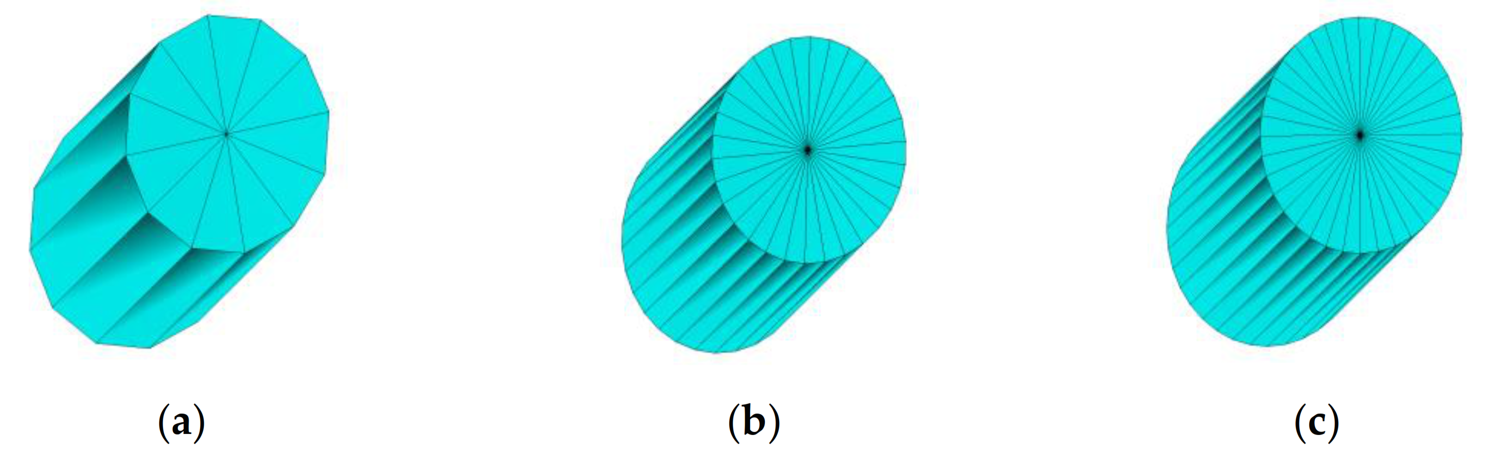
Variation in number of singular elements at the crack tip, (a) 12 equal parts (b) 30 equal parts (c) 36 equal parts.
Figure 5.
Variation in number of singular elements at the crack tip, (a) 12 equal parts (b) 30 equal parts (c) 36 equal parts.

Figure 6.
Theoretical shape of the plastic zone.

Figure 7.
Calculation process of thin-walled cylindrical shells with cracks.

Figure 8.
Mechanical model of a cylindrical shell subjected to eccentric compression.

Figure 9.
Geometric model of a thin-walled cylindrical shell with different cracks.

Figure 10.
Crack sections for linear elastic and elastic-plastic materials. (a) Section with circumferential crack for linear elastic material; (b) Section with circumferential crack for elastoplastic material.
Figure 10.
Crack sections for linear elastic and elastic-plastic materials. (a) Section with circumferential crack for linear elastic material; (b) Section with circumferential crack for elastoplastic material.

Figure 11.
Geometric description of singular elements at crack tip. (a) Original element, (b) Modified element.
Figure 11.
Geometric description of singular elements at crack tip. (a) Original element, (b) Modified element.

Figure 12.
Different elements on models of circumferential cracks and oblique cracks, (a) Element distribution of the model with a circumferential crack, (b) Element distribution of the model with an oblique crack, (c) Element distribution of the model with an oblique crack.
Figure 12.
Different elements on models of circumferential cracks and oblique cracks, (a) Element distribution of the model with a circumferential crack, (b) Element distribution of the model with an oblique crack, (c) Element distribution of the model with an oblique crack.

Figure 13.
Finite element model of thin-walled cylindrical shell model with circumferential crack.

Figure 14.
Symmetry surfaces and symmetry conditions for a circumferential crack.

Figure 15.
Finite element model of a thin-walled cylindrical shell model with an oblique crack. (a) Middle part of model, (b) Local area of model, (c) End region of model.
Figure 15.
Finite element model of a thin-walled cylindrical shell model with an oblique crack. (a) Middle part of model, (b) Local area of model, (c) End region of model.

Figure 16.
curves for different loads.

Figure 17.
curves for different eccentricities.

Figure 18.
Sizes of plastic zone for different external loads. (a) Sizes of plastic zone for different external loads when , (b) Sizes of plastic zone for different external loads when .
Figure 18.
Sizes of plastic zone for different external loads. (a) Sizes of plastic zone for different external loads when , (b) Sizes of plastic zone for different external loads when .

Figure 19.
curves for different eccentric compression.

Figure 20.
curves for different eccentricities.

Figure 21.
Von Mises Stress diagram for oblique cracks with different crack lengths (Pa). (a) Relative length coefficient , (b) Relative length coefficient , (c) Relative length coefficient .
Figure 21.
Von Mises Stress diagram for oblique cracks with different crack lengths (Pa). (a) Relative length coefficient , (b) Relative length coefficient , (c) Relative length coefficient .

Figure 22.
Von Mises Stress diagram for cracks with different oblique angles (Pa). (a) inclined crack angle , (b) inclined crack angle , (c) inclined crack angle , (d) inclined crack angle .
Figure 22.
Von Mises Stress diagram for cracks with different oblique angles (Pa). (a) inclined crack angle , (b) inclined crack angle , (c) inclined crack angle , (d) inclined crack angle .

Figure 23.
curves for different crack inclination angles.

Figure 24.
curves for different crack inclination angles.

Figure 25.
for different crack inclination angles.

Figure 26.
for different crack inclination angles.


Table 1.
Element 565 (SOLID95) with maximum circumferential tensile stress (Pa) when .
| Node | SX | SY | SZ | SXY | SYZ | SXZ |
|---|---|---|---|---|---|---|
| 35 | 1244.8 | 558.86 | −750.3 | 1043.8 | −108.1 | −83.4 |
| 36 | 1047.6 | 782.91 | −759.7 | 759.7 | −158.0 | −109.5 |
| 1 | 8080.1 | 12,458.0 | 3630.5 | −2564.7 | −1461.8 | 1099.3 |
| 1 | 8080.1 | 12,458.0 | 3630.5 | −2564.7 | −1461.8 | 1099.3 |
| 1957 | 1801.3 | 947.9 | −581.6 | 858.1 | −120.9 | −268.9 |
| 1958 | 1656.7 | 1217.9 | −548.4 | 605.8 | −151.3 | −323.4 |
| 1237 | 8443.0 | 14414.0 | 5637.1 | −2491.2 | 1500.5 | −307.2 |
| 1237 | 8443.0 | 14414.0 | 5637.1 | −2491.2 | 1500.5 | −307.2 |
Table 2.
Comparison of theoretical value and calculated result for different inclination angles (degree).
Table 2.
Comparison of theoretical value and calculated result for different inclination angles (degree).
| (º) | 0 | 10 | 20 | 30 | 40 | 45 | 50 | 60 | 70 | 80 |
| (º) | −70 | −67 | −64 | −60 | −56 | −53 | −50 | −43 | −33 | −19 |
| (º) | −70 | −60 | −60 | −60 | −50 | −50 | −50 | −40 | −40 | −20 |
Table 3.
Crack initiation angles (degree) calculated using finite element method when .
| ξ2 | 0.1 | 0.2 | 0.3 | 0.4 | 0.5 | 0.6 | 0.7 | 0.8 | 0.9 | 1.0 |
| (º) | −60 | −60 | −50 | −50 | −60 | −50 | −60 | −60 | −50 | −50 |
Table 4.
Crack initiation angles (degree) calculated using finite element method when .
| ξ2 | 0.1 | 0.2 | 0.3 | 0.4 | 0.5 | 0.6 | 0.7 | 0.8 | 0.9 | 1.0 |
| (º) | −60 | −60 | −50 | −60 | −60 | −50 | −60 | −60 | −70 | −50 |
Table 5.
Crack initiation angles (degree) calculated using finite element method when .
| ξ2 | 0.1 | 0.2 | 0.3 | 0.4 | 0.5 | 0.6 | 0.7 | 0.8 | 0.9 | 1.0 |
| (º) | −60 | −50 | −60 | −60 | −50 | −60 | −60 | −60 | −50 | −50 |
Publisher’s Note: MDPI stays neutral with regard to jurisdictional claims in published maps and institutional affiliations. |
© 2021 by the authors. Licensee MDPI, Basel, Switzerland. This article is an open access article distributed under the terms and conditions of the Creative Commons Attribution (CC BY) license (https://creativecommons.org/licenses/by/4.0/).
Share and Cite
MDPI and ACS Style
Yue, F.; Wu, Z. Fracture Mechanical Analysis of Thin-Walled Cylindrical Shells with Cracks. Metals 2021, 11, 592. https://doi.org/10.3390/met11040592
AMA Style
Yue F, Wu Z. Fracture Mechanical Analysis of Thin-Walled Cylindrical Shells with Cracks. Metals. 2021; 11(4):592. https://doi.org/10.3390/met11040592
Chicago/Turabian StyleYue, Feng, and Ziyan Wu. 2021. "Fracture Mechanical Analysis of Thin-Walled Cylindrical Shells with Cracks" Metals 11, no. 4: 592. https://doi.org/10.3390/met11040592
Note that from the first issue of 2016, this journal uses article numbers instead of page numbers. See further details here.