

Abstract
Kplo-MAGnetometer (KMAG) is one of the scientific instruments of Korea Pathfinder Lunar Orbiter (KPLO) set to be launched in 2022. Its objectives are magnetic field investigation and technical demonstration near the surface of the Moon. Specifically, it will investigate the lithospheric magnetism of the Moon and measure the electromagnetic wave properties near the lunar surface. It consists of three fluxgate magnetometers on a 1.2 m long boom, which is relatively shorter than the boom used in other missions. The three magnetometers are included for scientific measurements, redundancy checks, and multi-sensor technical investigation. The magnetometers and an inner Anisotropic Magneto-Resistive sensor perform simultaneous sampling to correct for the magnetic field interference caused by the spacecraft. The fully integrated flight model assembly showed that the magnetometer noise level was less than 30 pT Hz−1/2 at 1 Hz and stability was within ±0.2 nT at the 10 Hz sampling rate. This paper describes the configuration and performance of the KMAG using the multi-sensing method. KPLO, THEMIS-ARTEMIS spacecraft, and Commercial Lunar Payload Service modules will be in their operational phase simultaneously. Therefore, the KMAG will be able to contribute to multi-site in-situ measurements of the lunar magnetic field. We expect that the KMAG will provide an up-to-date lunar observation data set and an opportunity to perform the multi-sensor observation.
Export citation and abstract BibTeX RIS
1. Introduction
The lunar explorations have provided various kinds of answers to human questions about the Moon. However, continued lunar explorations have given rise to more curious questions, which require more scientific investigations and developments of novel technologies.
After the Luna (Soviet Union) and Ranger, Surveyor, and Apollo (United States) programs in the 1960s and 1970s, there were no lunar exploration missions for a decade. However, since the beginning of the 21st century, more than a dozen missions have been undertaken. Recently, many lunar exploration missions are announced, such as the sample-return phase of China's lunar exploration program (Li et al. 2019), Lunar Polar Exploration Mission of Japan (Hoshino et al. 2020), Chandrayaan-3 of India (Goswami 2020), and, the Lunar Gateway and Commercial Lunar Payload Services (CLPS) of the USA (Duggan et al. 2019). The Korea Pathfinder Lunar Orbiter (KPLO) mission is one such mission.
KPLO is the first step of the Korean space exploration program, including a planned orbiter, lander, and deep space missions. The design of the KPLO is shown in Figure 1. It is scheduled to launch in 2022 July using a Falcon 9. The KPLO will orbit the Moon at an altitude of 100 ± 30 km in a polar orbit for a one-year mission orbit period (Bae et al. 2017). According to the mission operation simulation, an extended mission for approximately eight months is possible at lower latitude.
KPLO has five scientific instruments (four from Korea and one from NASA) and one technical instrument: Lunar Terrain Imager by the Korea Aerospace Research Institute (Shin et al. 2018), Polarimetric Camera by the Korea Astronomy and Space Science Institute (Sim et al. 2019), KPLO Gamma-Ray Spectrometer by the Korea Institute of Geoscience and Mineral Resources (Kim et al. 2018), KPLO Magnetometer (KMAG) by Kyung Hee University, Shadow Camera by Arizona State University and Malin Space Science Systems (Robinson et al. 2017), and Disruption Tolerant Network by Electronics and Telecommunications Research Institute (Jo et al. 2016). The KPLO mission aims to conduct scientific investigations of the lunar environment and develop lunar exploration technologies.
The KMAG is one of the scientific instruments of KPLO. It will measure the magnetic field of the lunar surface and its surroundings. Specifically, it will investigate the lithospheric magnetism and electromagnetic wave properties of the Moon. The KMAG team expects to obtain new observation data set of the magnetic sounding of the lunar interior. This data will be helpful to THEMIS-ARTEMIS spacecraft and CLPS's space science payload, which will be operational at the same time as the KPLO.
The past lunar missions had two magnetic field measuring instruments: Magnetometer (MAG) of Lunar Prospector and Lunar Magnetometer (LMAG) of KAGUYA (Lin et al. 1998; Tsunakawa et al. 2010). They have provided excellent lunar magnetic field data at the various altitudes during their mission phase. Two global magnetic spherical harmonics models of the lithospheric field were produced from the observational data (Purucker & Nicholas 2010; Tsunakawa et al. 2015). KMAG may find it difficult to detect the lunar lithospheric magnetic field because the two models and past observation data suggest the presence of less than 1 nT of the lunar magnetic field at an altitude of 100 km, which may experience interference from the interplanetary magnetic field (IMF). Therefore, we are investigating a method to effectively remove the spacecraft field and IMF. During the 100 km altitude phase, KMAG will survey its surrounding environment and perform data calibration tasks, including observing the specific strong field region such as the magnetic anomalies. Additionally, during the extended phase of approximately eight months at the low-altitude—less than 70 km—KMAG is expected to produce more valuable data that will be used to investigate specific magnetic anomaly regions (Baek et al. 2017; Garrick-Bethell & Kelley 2019; Lee et al. 2019).
This paper introduces the KMAG payload of KPLO. The mechanical and electrical parts and their performances are described in Sections 2 and 3, respectively. A design study of the multi-sensing of three magnetometers is presented in Section 4. The conclusions are discussed in Section 5.
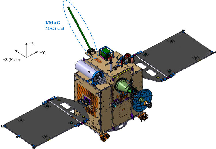
Figure 1. The KPLO spacecraft. KMAG is installed on the top floor of KPLO (+X side).
Download figure:
Standard image High-resolution image2. KMAG Payload Instrument
KMAG consists of two units: the MAG unit and Fluxgate magnetometer Control Electronics (FCE) unit, as shown in Figure 2. The MAG unit has three magnetometers, a 1.2 m long boom, hinge, and deployment mechanism. Furthermore, FCE consists of four electrical boards and their housing. The MAG unit is installed on a panel located outside the spacecraft. The boom will be pointed toward the nadir point during the in-orbit operation period.
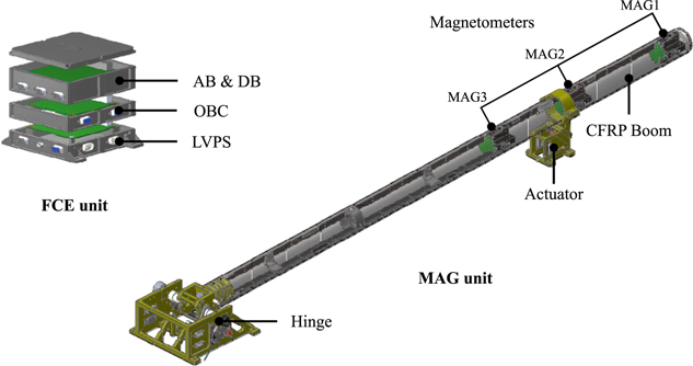
Figure 2. KMAG configuration: MAG unit and FCE unit. The MAG unit consists of the CFRP boom, actuator, and hinge. Three fluxgate magnetometers are located inside the boom, and MAG1 at the end of the boom is the primary magnetometer. The FCE unit consists of four electric boards and its housing. The boards are stacked using PC104 connectors.
Download figure:
Standard image High-resolution imageThe total mass and power consumption of KMAG is 3.5 kg and 4.6 W, respectively. The data communication protocol between KMAG and spacecraft is RS-422. Furthermore, it is expected to generate 295 Mbit per day of total magnetic field data at a 100% duty cycle. The major instrument specifications are listed in Table 1 and the detailed interface configuration of KMAG is shown in Figure 3.
Table 1. Major Instrument Specifications
| Parameter | Performance |
|---|---|
| Magnetometer | Three-axis fluxgate |
| Size | MAG unit: 1318 × 178 × 122 mm |
| FCE unit: 150 × 135 × 82 mm | |
| Mass | Total 3.5 kg |
| Power consumption | 4.6 W |
| Operational temperature | MAG unit: −55°C ∼ +70°C |
| FCE unit: −20°C ∼ +50°C | |
| Interface | RS-422, 115,200 bps |
| Data generation | 295.3 Mbit day−1 (duty 100%) |
Download table as: ASCIITypeset image
2.1. MAG Unit
KMAG has three magnetometers inside the boom. Like the past space missions, these magnetometers are placed as far as possible from the spacecraft with the help of a boom to reduce interference from the spacecraft. During the design phase, the length of the boom was decided to be 1.2 m considering the spacecraft design limitations and a field of view clearance of the other payloads. The boom was constructed using a carbon fiber reinforced plastic (CFRP) tube; it was verified to have 0.013% collected volatile condensible materials and a total mass loss of 0.41%.
We used an FC2 Frangibolt TiNiTM actuator for the boom deployment mechanism. The KMAG boom will be deployed at an angle of 135° from the top floor along with the other deployable units after separation from a launch vehicle.
2.2. Fluxgate Control Electronics
The FCE unit controls the KMAG system, including command and data communication of the spacecraft. It consists of four electrical boards: Analog Board (AB), Digital Board (DB), On-Board Computer (OBC), and Low Voltage Power Supply (LVPS). The size of each board is approximately 100 mm × 100 mm, and when connected with each other by the PC104 connector, it results in a stacking structure.
OBC manages the operations of the KMAG payload. It transmits the status and observed data to the spacecraft via the RS-422 interface. Additionally, command and telemetry are exchanged with the Standard Bus Management Unit (SBMU). The measured magnetic field data is transmitted to the Payload Data Handling Unit (PDHU) of the spacecraft as a Consultative Committee for Space Data Systems (CCSDS) packet form every 1 s. The OBC board contains a low-resolution three-axis Anisotropic Magneto-Resistive sensor (Honeywell's HMC1053) along with a temperature sensor to approximately measure the magnetic field from the spacecraft. It has a measurement range of ±60,000 nT with a 100 nT resolution. It will be used as an auxiliary reference value during the elimination of the magnetic interference by the spacecraft from the observations obtained by three magnetometers.
LVPS converts an unregulated +28 V from Power Control and Distribution Unit (PCDU) into ±5 VA, +5 VD, and +3.3 VD. It also contains an input power monitoring circuit and a power control circuit for boom deployment.
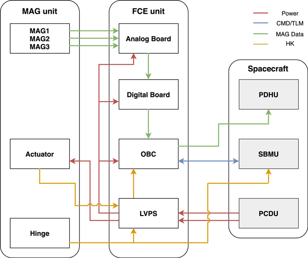
Figure 3. The KMAG system configuration and its interface with the spacecraft. The red lines depict the power supply lines. The blue line is command and telemetry transmission between KMAG and Standard Bus Management Unit (SBMU) of the spacecraft. Moreover, the green lines are the MAG data transmitted to the Payload Data Handling Unit (PDHU) of the spacecraft. The yellow lines transfer the status of the boom to the spacecraft for the purpose of its monitoring.
Download figure:
Standard image High-resolution imageThe driving circuit for three magnetometers consists of AB and DB. The key components of AB that are used to handle an analog signal chain of a magnetometer include an amplifier, oscillator, a demodulator, and a low-pass filter. The DB has an integrator, analog-to-digital converter (ADC), and a microcontroller. Figure 4 shows the working diagram of AB and DB for the one-axis of a magnetometer (Son 2012). The DB circuit consists of a 24 bit delta-sigma ADC to convert the analog signal of the magnetometer to the digital signal. ATmega8 microcontroller of the DB controls the ADC and sample-and-hold circuit and transmits the converted digital values to OBC as Transistor-Transistor Logic signal. The dynamic range of the magnetometer was kept fixed, during the development phase, using a resistor in the analog circuit. The final correction coefficients, such as gain and offset, were derived from a calibration process; they were then applied in the DB microcontroller.
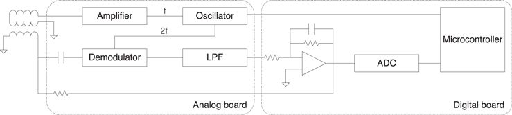
Figure 4. Analog feedback type circuit that drives only one of the three axes of the magnetometer. These circuits are divided into the Analog Board (AB), Digital Board (DB).
Download figure:
Standard image High-resolution image2.3. Magnetometer
KMAG has three racetrack fluxgate magnetometers. The primary magnetometer (MAG1) is located at the end of the boom; other magnetometers—MAG2 and MAG3—will be used for redundancies, magnetic interference corrections, and multi-sensor technical investigations. The core material of the fluxgate is a heat treated amorphous 2714A ribbon. The core has wound driving and sensing coils consisted of enameled copper wires with 0.2 mm and 0.12 mm diameters, respectively; the end of the coil wires are soldered on a magnetometer PCB.
A racetrack-shaped KMAG sensor core was inserted in an epoxy cylinder; the diameter and height of the cylinder were 45 mm each. The X- and Y-axis sensors were inserted in the middle of the cylinder, while the Z-axis sensor was inserted parallel to the boom. Figure 5 shows the structure of the KMAG magnetometer. The cylindrical-shaped fluxgate magnetometer housing was constructed to be lightweight, thermally balanced, and to provide easy access inside the boom.

Figure 5. KMAG fluxgate magnetometer structure and the assembled engineering model. Three MAGs are assembled on an L-shape rod to insert into the CFRP boom tube all at once.
Download figure:
Standard image High-resolution imageThree magnetometers were installed on an L-shaped rod, and their cable harnesses were also tied to the rod. This structure supports the alignment of three magnetometers and provides an easy assembly inside the CFRP boom. A disadvantage of this structure is that the harness path can affect MAG2 and MAG3. Therefore, we kept the harness path as far from magnetometers as we could.
The peak-to-peak resolution of the magnetometer at a 10 Hz sampling rate is less than 0.2 nT, and the noise is less than the required 30 pT Hz−1/2 at 1 Hz. These values were derived under a fully assembled Flight Model (FM). Table 2 shows the key performance of the magnetometer. The calibration test and its results are described in Section 3.
Table 2. The Requirement Specifications of the KMAG Magnetometer
| Parameter | Performance |
|---|---|
| Magnetometer type | Fluxgate (racetrack) |
| Measurable range | ±1000 nT |
| Resolution | <0.2 nT at 10 Hz sampling rate |
| Noise level | <50 pT Hz−1/2 at 1 Hz |
| Linearity | <5 × 10⁻³ |
| Axis alignment | <1 deg. |
Download table as: ASCIITypeset image
3. Performance
The calibration of the magnetometer was performed at a testing facility located inside a specific wooden house of the magnetometer company (Sensorpia Co.). We tested its properties, such as linearity, noise, and orthogonality. We also corrected zero-offset each axis of every magnetometer. The diameter of the Helmholtz coil inside a non-magnetic testing facility was approximately 1 m. It had a feedback control to eliminate the geomagnetic field variations. We used a three-layered mu-metal shielding chamber for long-term testing of FM assembly. It had shielding effectiveness of 99.9% for AC and DC magnetic fields. The test systems are shown in Figure 6. KMAG FM was calibrated and verified twice to check for a variation in each property after the final environment test. All tests were conducted at room temperature.
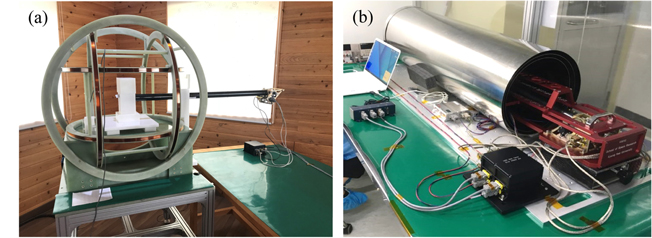
Figure 6. The test equipment for the calibration test. Figure 6(a) is the Helmholtz coil of a non-magnetic testing facility, and Figure 6(b) is a magnetic shielding chamber. The KMAG is located inside each test set to reduce the external field when it performs the calibration test.
Download figure:
Standard image High-resolution imageWe derived a scale factor—gain—and offset for each magnetometer from the calibration process. The calibration factors were then applied to the microcontroller of the digital board. Furthermore, the full-scale range and linearity were measured by changing the magnetic field at the center of the coil in steps of 100 nT.
We measured a full-scale range of approximately ±1400 nT and the linearity deviation of less than 0.1%. The derived results comply with the design requirements. Required full-scale range was ±1000 nT and required linearity was less than 0.5%. Figure 7 shows the linearity error of MAG1. Its X, Y, and Z components are 0.052%, 0.041%, and 0.032%, respectively, which are within the ±1000 nT measurement range. Table 3 shows the linearity error of all magnetometers.
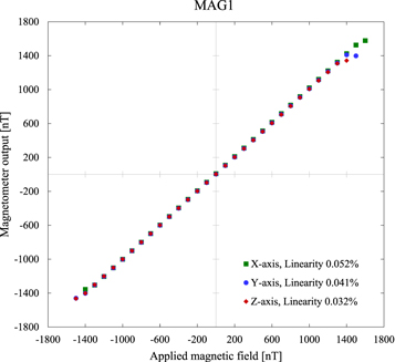
Figure 7. The linearity error of MAG1. The horizontal axis is the given magnetic field at the center of the Helmholtz coil, and the vertical axis means the measured value of the MAG1. This linearity error indicates the deviation between the given field and output of the magnetometer within the ±1000 nT measurement range.
Download figure:
Standard image High-resolution imageTable 3. The Linearity Error of Magnetometers
| Magnetometer | MAG1 | MAG2 | MAG3 |
|---|---|---|---|
| X-axis (%) | 0.052 | 0.031 | 0.036 |
| Y-axis (%) | 0.041 | 0.054 | 0.025 |
| Z-axis (%) | 0.032 | 0.038 | 0.038 |
Download table as: ASCIITypeset image
The orthogonality error was measured using the Helmholtz coil. We applied a constant magnetic field to only one axis of the coil and measured the orthogonality error by comparing the measured values of three axes. The average orthogonality error of all the three axes of each magnetometer was approximately 0.9°. Although few axes exceeded the orthogonality requirement (<1°), the released data will be corrected with orthogonality factors during the data processing.
After assembling all the parts of KMAG FM, the noise performances of the magnetometers were investigated within a three-layered shielding chamber using long-term operation data set. Figure 8 is shown a typical long-term operation data of MAG1. The KMAG magnetometer takes approximately an hour to stabilize after turning on the power. Therefore, all sample data sets were obtained after an hour. We used a boxcar averaging to remove weak magnetic field variation within the shielding chamber. Therefore, the stability of the magnetometer was confirmed to be less than 0.2 nT peak to peak at a 10 Hz sampling rate.
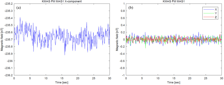
Figure 8. Long-term operation data and the stability of MAG1. Figure 8(a) shows data for the X-component for arbitrary 30 s during long-term operation. Figure 8(b) is constructed after removing all external field components (X, Y, and Z components are blue, green, and red line, respectively) at the same time.
Download figure:
Standard image High-resolution imageFigure 9 shows the noise of MAG1. The data consists arbitrary 5 minutes (3000 data points) of the long-term operation data set after the system was stabilized. We applied Welch's method of spectrum estimation based on fast Fourier transform on the data to determine the noise distribution with frequency. The X, Y, and Z components were 28 pT Hz−1/2, 25 pT Hz−1/2, and 26 pT Hz−1/2 at 1 Hz, respectively. The average noise of all the magnetometers was approximately 26 pT Hz−1/2 at 1 Hz, which satisfied the noise requirement of less than 50 pT Hz−1/2.
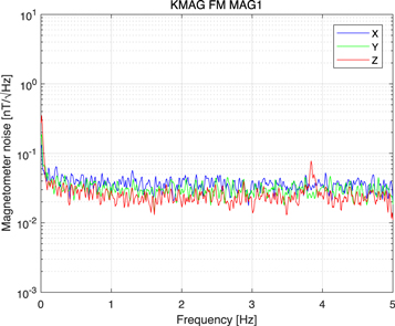
Figure 9. The noise of MAG1. All components (X, Y, and Z) are less than 30 pT Hz−1/2 at 1 Hz. The peak of the Z-component at approximately 3.8 Hz is estimated to the noise caused by the test environment.
Download figure:
Standard image High-resolution imageThe result of Figure 9 shows the unexpected Z-component peak at approximately 3.8 Hz. We further examined the peak value by performing a test keeping a search-coil magnetometer used for ground observation (Shin et al. 2016) inside the shielding chamber. The test showed that the noise was over 20 dB at approximately 3.8 Hz. Hence, we confirmed that the noise was generated due to the FM test-lab environment.
4. Multi-sensing of Three Magnetometers
The magnetic field measurement data of KMAG may have a target field affected by the induced field, IMF, and spacecraft interference field. We can remove the spacecraft magnetic interference using multi-sensing of three magnetometers using in-orbit calibration. Therefore, the position of each magnetometer was determined considering the difference in the magnetic field with respect to the distance from the spacecraft.
During the cruising phase, the magnetic field measurement of each magnetometer (Bmeasure) can be represented as

where Bambient, BS/C, and Bsensor represent an external magnetic field, the magnetic interference by the spacecraft, and the offset of the magnetometer, respectively, as shown in Figure 10 (Ness et al. 1971; Acuña 2002).

Figure 10. Illustration of a magnetic field around the spacecraft. The measured magnetometer value may contain an ambient field, magnetic interference by the spacecraft, and the noise from the sensor.
Download figure:
Standard image High-resolution imageWe have to remove the magnetic interference of the spacecraft (BS/C) and the offset of the magnetometer (Bsensor ) from the observation value (Bmeasure) of Equation (1) in order to obtain the ambient field (Bambient) as our target value. Bsensor is the property of each magnetometer, which is determined by the calibration test. BS/C values of three magnetometers are different by the location of the magnetometer because it decreases inversely to the distance from the magnetic interference source, whereas Bambient values of the three magnetometers measured simultaneously should be the same. Therefore, if the location of the magnetometer is determined, we can define BS/C at that location and correct it from the observation value. It is a reasonable estimation for KMAG, which has a short boom length.
We assumed, to determine magnetometers location, that a source of magnetic disturbance is near the KMAG hinge structure, which is the closest location effected to the MAG1 primary magnetometer at the end of the boom. Thereafter, the locations of MAG 2 and MAG3 were fixed to the position where the value of magnetic field interference was measured to be twice the MAG1 and MAG2, respectively. Thus, the magnitude of the magnetic interference of each magnetometer can be expressed as

where BS/C is calculated using the Biot–Savart law. The source of magnetic interference was assumed to be a dipole moment. Furthermore, the distance ratios of each magnetometer from the source are 1:0.79:0.792 (dMAG1:dMAG2:dMAG3).
KMAG will carry out an in-orbit calibration during the KPLO cruise phase and commissioning phase upon insertion into the lunar orbit. During this time, first, KMAG will turn on, and then other payloads will power up sequentially to measure the magnetic disturbance generated by the other instruments of KPLO.
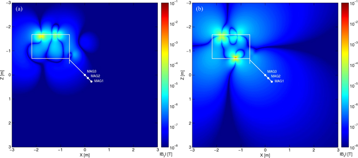
After the critical design review (CDR), to verify the spacecraft compliance of KMAG requirements, we performed a numerical simulation and estimated the magnetic field interference generated by the spacecraft. We assumed a dipole moment for all instruments in KPLO that could be the magnetic interference source. The magnetic momentums for 25 instruments of KPLO, such as the reaction wheel, are mentioned in the instrument datasheet and CDR report. Figure 11 shows the presence of interferences generated by the instrument of KPLO near the KMAG magnetometers. Its X, Y, and Z values at the MAG1 are +85 nT, −11 nT, and +188 nT, respectively. It marks one of the worst-case results. These values are larger than other missions using a several times longer boom. But these values are in an allowable range which is able to eliminate an unwanted field using multi-sensing technique.
Figure 11. Modeling of the magnetic interference by the spacecraft. This is a worst-case scenario in which the magnetic moment of all instruments are aligned in the same direction to the +X-axis. The solid white line and dots show a cross-section (XZ plane) of KPLO and the location of KMAG magnetometers, respectively. The origin of the figure marks the location of MAG3, which is close to the spacecraft. Each axis represents a spacecraft coordinate, and +Z marks the nadir point of KPLO. Figures 11(a) and (b) show Y-component and Z-component of the spacecraft magnetic field disturbance, respectively.
Download figure:
Standard image High-resolution image
5. Conclusions
KPLO is the first Korean lunar mission demonstrating technical and scientific research of the Korean space exploration program. KMAG—one of the scientific instruments of KPLO—was constructed mostly using commercial grade parts; all the parts passed the KPLO environment test requirements. The performance, calibration results, instrument configurations are presented in this paper.
Three fluxgate magnetometers were installed inside the boom to enhance the observation data reliability using redundancy sensing and multi-sensor technical investigation. The length of the boom was determined to be 1.2 m considering the mass and space limitations of the spacecraft. We performed FM functional tests to verify command and data communications including, sensor monitoring, boom deployment, and normal sequence of operation. The magnetometer stability of the fully assembled KMAG and average noise of all the magnetometers were measured during the long term ground test, values of which were ±0.2 nT maximum peak to peak and less than 30 pT Hz−1/2, respectively.
The scientific objectives of KMAG are: to investigate permanent magnetization of the lithosphere and measure time-dependent field variations from plasma phenomena on the lunar surface and in its surroundings. Fortunately, KPLO will be operational when two THEMIS-ARTEMIS spacecraft and CLPS modules. This unique situation will allow various multi-site in-situ measurements, including IMF. We expect that the KMAG will provide state-of-the-art data set and pave the way for multi-sensor observation in future space missions.
This work was supported by NRF-2016M1A3A9913306 and NRF-2020M1A3B7109194 programs of the National Research Foundation, Ministry of Science, and ICT of Korea.