


1 Introduction
Thulium-doped laser media can be used in diode-pumped solid-state lasers emitted in the short-wave infrared (SWIR) range, from about 1.8 μm to 2.05 μm. As this wavelength range allows for strong absorption in water, such lasers have found a number of applications, e.g., in medicine for ThuLEP treatment[Reference Herrmann, Bach, Imkamp, Georgiou, Burchardt, Oelke and Gross1]. Furthermore, Tm:YAG lasers can serve as a well-adapted pump source for laser systems using Cr:ZnSe as the active material. The latter exhibits an extremely broad emission spectrum in the SWIR regime, which makes thulium lasers in combination with Cr:ZnSe a promising candidate for the basis of high-power laser systems generating ultra-short pulses in the SWIR[Reference Vasilyev, Moskalev, Mirov, Smolski, Mirov and Gapontsev2]. Accordingly, a prototype operating with nanosecond pulses has been demonstrated to generate up to 50 mJ output energy[Reference Yumoto, Saito and Wada3]. Such a system could also be seeded with ultra-short laser pulses, therefore underlining the potential for the realization of a new generation of high-intensity lasers operating in the mid-infrared range[Reference Danson, Haefner, Bromage, Butcher, Chanteloup, Chowdhury, Galvanauskas, Gizzi, Hein, Hillier, Hopps, Kato, Khazanov, Kodama, Korn, Li, Li, Limpert, Ma, Nam, Neely, Papadopoulos, Penman, Qian, Rocca, Shaykin, Siders, Spindloe, Szatmári, Trines, Zhu, Zhu and Zuegel4].
For such laser systems, however, high-efficiency and well-suited pump lasers – adapted with respect to the pump wavelength and the pulse duration – are required. In addition to good overlap of the absorption in Cr:ZnSe with the emission of thulium-based lasers, such lasers exhibit a range of other advantages. Using thulium-based laser materials, the absorption bands being close to 800 nm enable the use of available high-power laser diodes, which are already used as pump sources for neodymium-based systems. Despite the large difference between pump and laser wavelengths, the latter lying in the range between 1.8 and 2.1 μm, with a quantum efficiency of up to 2 results in a quantum defect of the order of only 20%. This is a consequence of the cross-relaxation process, through which two active ions are excited by a single pump photon.
Another advantage of using thulium-doped laser media is their long fluorescence lifetime, which is significantly longer than for ytterbium- or neodymium-doped materials. With yttrium aluminum garnet (YAG) as the host material, the radiative lifetime is 15 ms[Reference Körner, Lühder, Reiter, Uschmann, Marschner, Jambunathan, Lucianetti, Mocek, Hein and Kaluza5], which is almost 15 times longer than the lifetime of Yb:YAG[Reference Körner, Jambunathan, Hein, Seifert, Loeser, Siebold, Schramm, Sikocinski, Lucianetti, Mocek and Kaluza6].
Therefore, in the last decade, several diode-pumped laser systems have been reported that utilize Tm:YAG as the active medium in a Q-switch operation system, multi-millijoule pulses with wavelengths between 2.01 and 2.02 μm. Most of these systems are operated at a repetition rate in excess of 500 Hz while being pumped with continuous-wave diodes. Such systems have been demonstrated to be capable of generating pulse energies of up to 20 mJ[Reference Zhang, Wang, Xu, Wang, Tang, Cheng, Chen, Xu, Jiang and Pan7–Reference Jin, Liu, Liu, Huang, Yao and Shen10]. Higher energies of more than 100 mJ have also been reported using a pulse-pumped system with a repetition rate of 10 Hz[Reference Yumoto, Saito, Urata and Wada11].
When considering the use of such lasers as a pump source for Cr:ZnSe, however, the 1.88 μm emission of Tm:YAG is favorable, since a better overlap with the absorption bands is obtained, which would significantly enhance the efficiency of such a laser system. So far, however, there are only a few references for laser operation of Tm:YAG at 1.88 μm. The available data is mainly restricted to continuous-wave operation of wavelength-tunable lasers[Reference Gao, Ma, Xie, Zhang, Luo, Yang, Tang, Ma, Yuan and Qian12, Reference Thomas, Tonelli, Veronesi, Cavalli, Mateos, Petrov, Griebner, Li, Pan and Guo13] and to a Bragg grating-stabilized laser[Reference Gao, Yue, Feng, Li and Gao14].
Recently, it has also been demonstrated that cryogenic cooling can significantly improve the efficiency of Tm:YAG lasers[Reference Li, Yan, Liang and Cai15]. In particular, for an operation at 1.88 μm, as realized in the laser system described here, the cross-sections at this wavelength are significantly larger under cryogenic conditions than at room temperature. Furthermore, the thermal occupation of the lower laser level is reduced significantly, transforming a quasi three-level system at room temperature into a four-level system[Reference Körner, Lühder, Reiter, Uschmann, Marschner, Jambunathan, Lucianetti, Mocek, Hein and Kaluza5].
In this paper, we present results from an active electro-optical Q-switched laser system using Tm:YAG as the active medium and a rubidium titanyle phosphate (RTP) Pockels cell. Since this laser has been developed to serve as a pump source for future chromium-doped high-energy laser amplifiers, the laser system was designed to operate at the 1.88 μm emission line. To increase the performance at this wavelength, the laser crystal was cryogenically cooled to approximately 120 K and the overall system was enclosed in a dry atmosphere. Furthermore, since in our concept the repetition rate is less important than the maximum output energy, the laser used a pulse-pumped approach, which allowed the energy storage capability of the laser medium to be maximized. With the prototype presented here, a maximum output energy of 2.53 mJ in a 650 ns pulse was achieved in Q-switch operation with 28 W laser diode peak power for pumping. When using cavity dumping the pulse duration was shortened to 18 ns with a slightly lower output energy of 2.22 mJ. With these parameters, we believe to be presenting the first Q-switched Tm:YAG laser emitting at 1.88 μm, which also represents a first important step toward realizing a well-adapted, pulse-pumped source for Cr:ZnSe lasers.
2 Considerations on the pump source
To reduce the complexity of the pump laser required for a high-energy thulium laser, it is desirable to use the maximum energy storage capability of the laser medium, thus minimizing the necessary diode pump peak power. Furthermore, since in such lasers the pulse repetition rate can typically be low compared with the inverse fluorescence lifetime, a pulse pumping approach allows the use of more powerful laser diodes designed for quasi-continuous operation mode. The latter also reduce the need for cooling capacity, both for the pump diodes and for the laser medium itself.
Thulium-doped gain media in general exhibit a long radiative lifetime of the upper laser level. For Tm:YAG, values given in the literature reach 15 ms, which is about 15 times longer than that for Yb:YAG. If this could be exploited, one could store the same amount of energy in the laser medium with a pump source having only one fifteenth of the power that would be required for an equivalent Yb:YAG laser. Therefore, to avoid significant saturation of the gain medium induced by the pump beam, the pump intensities need to be adapted.
In the following we use a simplified model to describe the pump process, in order to estimate an adequate pump intensity in an end-pumped layout. We consider the ground state 3H6 to have the occupation density  ${N}_1$, the excited state 3H4 to have
  ${N}_2$ and the upper laser manifold 3F4 to have
  ${N}_3$. In general the spontaneous decay of the 3H4 and the 3F4 states to the 3H6 state can be represented by the corresponding fluorescence lifetimes
  ${\tau}_{21}$ and
  ${\tau}_{31}$. In addition, the cross-relaxation process can be modeled as well, with the lifetime of the corresponding transition
  ${\tau}_{23}$, while it needs to be considered that each decay of the 3H4 state to the 3F4 manifold excites an additional ion from the 3H6 manifold to the 3F4 manifold. The absorption of the pump is modeled with the pump photon density
  ${\varPhi}_{\mathrm{p}}$ and the corresponding absorption cross-sections
  ${\sigma}_{\mathrm{a}}$ of the 3H6 to 3H4 transition. Therefore, we obtain the following set of rate equations:
 $$\begin{align}\frac{\mathrm{d}{N}_1}{\mathrm{d}t}&=-{\sigma}_{\mathrm{a}}c{\varPhi}_{\mathrm{p}}\cdot \left({f}_1{N}_1-{f}_2{N}_2\right)+\frac{N_2}{\tau_{21}}+\frac{N_3}{\tau_{31}}-\frac{N_2}{\tau_{23}},\end{align}$$
 $$\begin{align}\frac{\mathrm{d}{N}_2}{\mathrm{d}t}&={\sigma}_{\mathrm{a}}c{\varPhi}_{\mathrm{p}}\cdot \left({f}_1{N}_1-{f}_2{N}_2\right)-\frac{N_2}{\tau_{21}}-\frac{N_2}{\tau_{23}},\end{align}$$
 $$\begin{align}\frac{\mathrm{d}{N}_3}{\mathrm{d}t}&=2\cdot \frac{N_2}{\tau_{23}}-\frac{N_3}{\tau_{31}}.\end{align}$$
Here,  ${f}_1$ and
  ${f}_2$ are the Boltzmann distribution factors of the corresponding manifold and
  $c$ is the speed of light.
For further simplification we consider the cross-relaxation process to be ideal. Hence, ions in the 3H4 state are assumed to instantaneously cross-relax to the 3F4 manifold. This results in  ${N}_2\approx 0$,
  ${N}_2{\tau}_{21}\approx 0$ and
  $\frac{\mathrm{d}{N}_2}{\mathrm{d}t}\approx 0$. Therefore, the rate equations can be simplified using
 $$\begin{align}\frac{N_2}{\tau_{23}}={\sigma}_{\mathrm{a}}c{\varPhi}_{\mathrm{p}}\cdot {f}_1{N}_1.\end{align}$$
This leads to a simplified set of rate equations:
 $$\begin{align}\frac{\mathrm{d}{N}_1}{\mathrm{d}t}&=-2{\sigma}_{\mathrm{a}}c{\varPhi}_{\mathrm{p}}\cdot {f}_1{N}_1+\frac{N_3}{\tau_{31}},\end{align}$$
 $$\begin{align}\frac{\mathrm{d}{N}_3}{\mathrm{d}t}&=2{\sigma}_{\mathrm{a}}c{\varPhi}_{\mathrm{p}}\cdot {f}_1{N}_1-\frac{N_3}{\tau_{31}}.\end{align}$$
 From this we can conclude that, owing to the cross-relaxation process, the efficiency of the pump process is strongly increased compared with a common pump system, which is due to the generation of two excited ions per absorbed photon, indicated by the factor of 2 in front of  ${\sigma}_{\mathrm{a}}$, hence doubling the pump rate. Furthermore, since the 3H4 manifold is always unoccupied, the absorption saturates, owing only to missing ions in the ground state, but not to the balance of re-emission owing to ions in the upper pump state.
To obtain a simpler expression we replace the number density of excited states by the relative inversion density  $\beta ={N}_3/{N}_{\mathrm{dop}}$, where
  ${N}_{\mathrm{dop}}={N}_1+{N}_3$ is the density of dopant ions. Furthermore, we use the pump rate
  $R={\sigma}_{\mathrm{a}}c{\varPhi}_{\mathrm{p}}$ to describe the pump radiation. Hence, we obtain
 $$\begin{align}\frac{\partial \beta }{\partial t}=2{Rf}_1-\beta \cdot \left(2{Rf}_1+\frac{1}{\tau_{31}}\right).\end{align}$$
 In the following we consider a so-called ‘end-pumped’ layout, where pump and laser beams are co-propagating. Therefore, the absorption leads to a spatial dependence of  $R(z)$:
 $$\begin{align}\frac{\partial R}{\partial z}=-R(z){\sigma}_{\mathrm{a}}{f}_1{N}_{\mathrm{dop}}\cdot \left(1-\beta\right).\end{align}$$
 Since  $R$ and
  $\beta$ are linked, both parameters depend on space and time, leading to a two-dimensional differential equation system that is treated numerically.
In Figure 1 the results from a numerical simulation for the equation system are shown. For the calculations, the Boltzmann factor was assumed to be  ${f}_1\approx 1$. In accordance with the laser system, which is presented in Section 3, we assumed a Tm:YAG crystal with a doping concentration of 8% (atomic fraction) and a pump wavelength of 786.5 nm. The temperature was 120 K, which, according to the data given in Ref. [Reference Körner, Lühder, Reiter, Uschmann, Marschner, Jambunathan, Lucianetti, Mocek, Hein and Kaluza5], results in
  ${\sigma}_{\mathrm{a}}=1.9\times {10}^{-20}\,$cm2.
  ${\tau}_{\mathrm{f}}$ was assumed to be 15 ms.
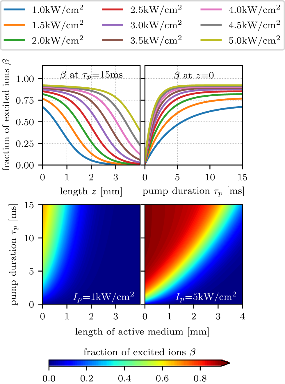
Figure 1. Results from the numerical simulation of the pump process in an 8% (atomic fraction) doped Tm:YAG crystal with a pump duration of 15 ms assuming a fluorescence lifetime of 15 ms. Upper left graph: relative inversion density  $\beta$ as a function of the penetration depth
  $z$ in the laser crystal for different pump intensities at the end of the pump pulse. Upper right graph: relative inversion density
  $\beta$ on the crystal’s entrance surface as a function of the pump duration
  ${\tau}_{\mathrm{p}}$ for various pump intensities. Lower graphs: relative inversion density
  $\beta$ as a function of the penetration depth
  $z$ (horizontal) and pump duration
  ${\tau}_{\mathrm{p}}$ (vertical) for a pump intensity of 1 kW/cm2 (left) and 5 kW/cm2 (right).
The simulated pump intensity was varied from 1 kW/cm2 to 5 kW/cm2 for a pump pulse duration equal to  ${\tau}_{\mathrm{f}}$. Though such pump intensities are quite low compared with common pump intensities, e.g., as used in ytterbium-based lasers, strong saturation effects are already evident. Regarding the laser design this indicates that the pump fluences used in pulse-pumped systems should be kept sufficiently low to avoid strong saturation. Furthermore, high inversion should be avoided in such systems.
In practice this means that, for thulium-based end-pumped lasers, pump fluences of about 10% of those typical for ytterbium-based systems would be sufficient if the fluorescence lifetime is not significantly quenched. Higher fluences would lead to saturation in the active medium and therefore result in a highly inverted area that is pushed through the active medium over the pump’s emission time. Such high inversion in the active medium would increase the influence of the energy transfer up-conversion (ETU) process, leading to an energy loss for the laser process and additional heating within the active medium. As a result this would lead to a reduced efficiency and high thermal load, shortening the effectively usable fluorescence lifetime.
The laser prototype presented here is designed with a pump fluence of 7.7 kW/cm2. With respect to the simulation results such a pump fluence would already lead to strong saturation. Nevertheless, we chose this high value so that sufficient pump power is also available in case of a significantly shortened fluorescence lifetime in the crystal used, as is to be expected given previous spectral investigations on the same crystal in Ref. [Reference Körner, Lühder, Reiter, Uschmann, Marschner, Jambunathan, Lucianetti, Mocek, Hein and Kaluza5]. However, compared with typical values, e.g., for Yb:YAG, which are in the range of 10 kW/cm2 to 30 kW/cm2, this is still relatively low. To further increase the power reserve in our setup we also used a multi-pass system for the pump to recycle transmitted pump light.
3 Setup
A schematic drawing of the laser setup is shown in Figure 2. For the pump source, we used a fiber-coupled (105 μm core diameter, NA=0.22, multi-mode) laser diode with a maximum output power of 30 W and a central wavelength of 793 nm (BWT Beijing Ltd). The fiber’s output facet was imaged onto the laser crystal, which acted as an active mirror, with a magnification factor of 6.7 using an achromatic lens L1 with 30 mm focal length and a plano-convex lens L2 with 200 mm focal length. The latter lens was used with off-center incidence, resulting in an angled incidence on the active mirror. Therefore, the reflected transmitted pump beam was spatially separated from the incident beam, allowing the imaging of the pump beam for a second time onto the active medium, using a right-angle prism P as the retro-reflector. The beam positions on the lens L2 are shown in the inset of Figure 2, with the numbering corresponding to their passing order. This setup resulted in a total of two double passes through the active medium. The diode beam and the intraresonator mode were separated by a dichroic mirror DM under an angle of incidence of 22.5°, which transmitted the pump radiation and reflected the laser wavelength.
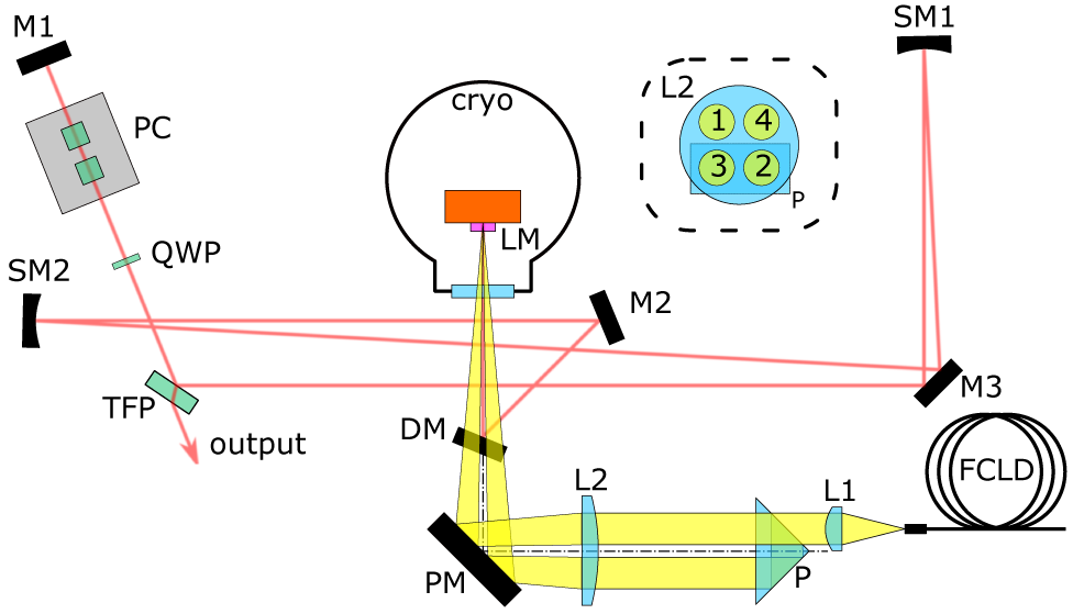
Figure 2. Schematic of the laser setup. The dashed box inset shows the hit points of the pump beam on L2 and P. Cryo, high-vacuum cryostat; DM, dichroic mirror; FCLD, fiber-coupled laser diode; L1 and L2, lenses; LM, active mirror laser medium; M1, M2, M3, turning mirrors; P, retro-reflector prism; PC, Pockels cell; PM, pump turning mirror; QWP, quarter wave plate; SM1 and SM2, spherical mirrors; TFP, thin-film polarizer.
The spot of the pump had a diameter of approximately 0.7 mm, corresponding to 7.7 kW/cm2. This was higher than the theoretically proposed pump intensity, to allow for power reserve for a shorter pump pulse duration, as ETU and other non-radiative decay mechanisms could shorten the fluorescence lifetime and therefore limit the useful maximum pump pulse duration  ${\tau}_{\mathrm{p}}$. This was expected, as the doping concentration of our Tm:YAG sample of 8% (atomic fraction) was relatively high, which makes our setup prone to suffer from such effects.
The laser crystal had a 5 mm diameter circular aperture and a thickness of 1.25 mm. It was mounted in a high-vacuum ( $\approx$10−6, 1 mbar = 100 Pa) bath cryostat and thermally coupled to the liquid nitrogen reservoir using copper wires to minimize mechanical movements. Furthermore, the crystal was mounted – thermally insulated – in a remotely adjustable mount, allowing for alignment in the cooled state as well.
To match the absorption bands of Tm:YAG the pump diode was cooled to approximately 0°C in a dry atmosphere, resulting in a central wavelength of approximately 783 nm with a full width at half maximum bandwidth of 2.5 nm for pulses of 1.6 ms at 1 Hz. This fits well with the absorption of Tm:YAG at cryogenic temperatures[Reference Körner, Lühder, Reiter, Uschmann, Marschner, Jambunathan, Lucianetti, Mocek, Hein and Kaluza5].
The laser resonator shown in Figure 2 had two plane-end mirrors, with one being the active mirror laser medium (LM) and the other M1. The spherical mirrors SM1 (500 mm focal length) and SM2 (250 mm focal length) divided the cavity into three sections. The first section between M1 and SM1 was 1150 mm long and incorporated the output coupling and polarization optics. In quasi-continuous wave (QCW) operation mode the quarter wave plate (QWP) was used to adjust the amount of output coupling at the thin-film polarizer (TFP). In Q-switch and cavity dump mode the QWP was aligned for 100% transmission of the back-reflected beam from M1 at the TFP. The output coupling was then switched using the RTP Pockels cell (PC) with a 6 mm rectangular aperture (Raicol Crystals Ltd.).
The second section lay between SM1 and SM2 and was 850 mm long, and the third section lay between SM2 and LM and was 500 mm long, resulting in a mode radius of 0.5 mm for a TEM00 beam at the position of the active medium.
The layout was designed to tolerate a thermal lens down to the range of approximately 1 m in the active medium without a disruptive influence on the actual mode size.
All optics were optimized for the 1.88 μm emission line of Tm:YAG, which also has the highest emission cross-section at low temperatures. Since water vapor absorption in air would be problematic at this wavelength, the complete setup was housed in a tent purged with synthetic dry air to maintain a relative humidity of less than 5% during operation. During the first tests of the laser system we found that without this measure the laser ran highly unstable in QCW operation mode, while operation in Q-switch mode was not possible at all.
4 Results and discussion
First tests with the system were carried out in QCW operation mode. The pump diode was operated at 28 W peak power in pulsed mode. The output was analyzed using a photo diode. It was found that the power of the QCW pulses did not reach a stable intensity after the initial spiking, but a drop in intensity was observed with increased pulse duration. For pump pulse durations in excess of 5 ms the QCW output stopped before the end of the actual pump pulse. Also, the overall output power decreased for repetition rates higher than 1 Hz. Both results indicate that a significant amount of heat was generated during operation.

Figure 3. Output energy  ${E}_{\mathrm{out}}$, optical-to-optical efficiency
  ${\eta}_{\mathrm{oo}}$ and full width at half maximum output pulse duration
  ${\tau}_{\mathrm{out}}$ as functions of the pump pulse duration in Q-switch operation. The pump diode was operated at 28 W peak power and 1 Hz repetition rate. The secondary x-axis on top indicates the total pump energy
  ${E}_{\mathrm{pump}}$ applied.
According to a prior thermo-mechanical simulation, considering only the heat generated due to the quantum defect, a temperature increase of only a few kelvins was to be expected for a significantly higher duty cycle. Therefore, to explain the observations of the QCW experiments it was to be assumed that the amount of generated heat is significantly higher, which could be caused by ETU or multi-phonon relaxation. This limits the achievable output parameters of the system in our case. For higher performance in future systems the use of crystals with lower doping would be favorable.
All measurements presented in the following were taken with the pump laser diode operating at a repetition rate of 1 Hz and a peak power of 28 W. The crystal temperature was fixed at approximately 120 K.
Q-switched operation was realized by adjusting the QWP to 90° polarization rotation in double pass, resulting in a 100% output coupling at the TFP. The PC was switched at the end of the pump pulse. The switching voltage was adjusted to obtain the maximum output energy. In Figure 3 the output energy  ${E}_{\mathrm{out}}$, optical-to-optical efficiency
  ${\eta}_{\mathrm{oo}}$ and the corresponding full width at half maximum output pulse duration
  ${\tau}_{\mathrm{out}}$ are presented as functions of the pump pulse duration.
The maximum output energy of 2.53 mJ was achieved for a pump pulse duration of 1.65 ms, which is significantly shorter than the fluorescence lifetime. This further indicates that non-radiative decay processes play a significant role. The maximum optical-to-optical efficiency, calculated as the ratio of the output energy to the optical pump pulse energy, of just above 6% was achieved for an even shorter pump pulse duration close to 1 ms, indicating the lowest relative loss due to fluorescence and non-radiative decay mechanisms.
The temporal output pulse shape as shown in the left-hand graph in Figure 4 corresponds to a typical Q-switched pulse. The intracavity signal was recorded using a DET10D/M photo diode (Thorlabs, Inc.), while the output signal, which has a larger bandwidth, was recorded with a PDA30G-EC photo diode (Thorlabs, Inc.). Therefore, while the intracavity diode showed a smooth signal, the output diode was capable of partly resolving the temporal modulations caused by the longitudinal multi-mode operation of the cavity. The shortest pulse duration of approximately 650 ns was achieved for a pump pulse duration close to 1.6 ms, which coincided with the settings for maximum output energy, though for shorter pump pulse duration down to 1.05 ms no significant change in pulse duration was observed.
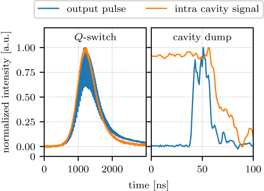
Figure 4. Temporal pulse shapes of the intracavity signal and the output pulse at maximum energy.
The spatial output profile as shown in Figure 5 nearly resembles a TEM00 Gaussian beam. Within the presented parameter range of the laser system, the output profile was widely unaffected despite the absolute intensity.

Figure 5. Output laser profile in Q-switch operation. The black curves at the sides are the averaged cross-sections.
To achieve a shorter pulse duration the cavity was also tested in cavity dump mode. Therefore the PC voltage was further increased to achieve maximum intracavity intensity and minimum output coupling. The PC was switched off when the maximum intracavity intensity was reached, releasing the energy stored in the cavity within one round-trip. Therefore, the output pulse duration of 18 ns corresponds to the actual round-trip time of the cavity. The corresponding output pulse shape is shown in Figure 4 on the right-hand side. In this operation system the cavity is also in multi-mode operation causing the temporal modulations. Aside from the modulations the pulse shape is close to a temporal flat-top, as is to be expected in this operation mode.
The cavity dump operation was realized with a pump pulse duration of 1.65 ms. The achieved output energy of 2.22 mJ was slightly lower compared with that with normal Q-switch operation.
5 Conclusions
We have reported on what we believe to be the first Q-switched cryogenically cooled Tm:YAG laser operating at 1.88 μm. The system generated pulses of 2.53 mJ energy with a repetition rate of 1 Hz and a pulse duration of approximately 650 ns in Q-switch operation. Shorter pulses of 18 ns were obtained in cavity dump mode with a slightly lower output energy of 2.22 mJ corresponding to a peak power of 0.123 MW. The highest output energy was obtained with a pump pulse duration of 1.65 ms, while the optical-to-optical efficiency of the laser was around 6%.
According to a numerical simulation of the simplified laser process, the results indicate that, owing to the high doping level of 8% (atomic fraction) of our Tm:YAG sample, non-radiative decay, especially ETU, played a significant role, as a fluorescence lifetime close to 15 ms has been demonstrated before in spectral measurements[Reference Körner, Lühder, Reiter, Uschmann, Marschner, Jambunathan, Lucianetti, Mocek, Hein and Kaluza5]. Therefore, using crystals with a lower doping level should enable the use of longer pump pulses and therefore achieve higher output energies in future setups, which could then be used as a pump source for broadband Cr:ZnSe laser amplifiers.
Acknowledgments
It is with profound sorrow that the authors inform you of the passing of their highly respected and beloved colleague, Antonio Lucianetti, after an insidious illness. He left this world calmly on 19 November 2020, in Bergamo at the age of 55.
Funding
This project has received funding from the European Union’s Horizon 2020 research and innovation programme (871124 Laserlab-Europe and 739573); the Thuringian Ministry for Economic Affairs, Science and Digital Society (2016FE9058); Bundesministerium für Bildung und Forschung (BMBF) (03ZIK445, 05P15SJFA1, 03Z1H531, 03VNE2068D); the European Regional Development Fund and the state budget of the Czech Republic (project HiLASE CZ.02.1.01/0.0/0.0/15_006/0000674) and the Ministry of Education, Youth and Sports of the Czech Republic (NPU I Project No. LO1602).


 Open access