Conceptual Design of a Modular Floating Multi-Purpose Island
 Ingo Drummen
 Gerrit Olbert
- 1MARIN, Wageningen, Netherlands
- 2TU Hamburg, Hamburg, Germany
The design of a modular floating multi-purpose island inherently involves interaction within a group with a large range of backgrounds such as engineering, architecture, sociology, climate modeling, and more. A heuristic design approach was adopted for future island developers to make a first conceptual design. Four major design considerations were distinguished to discretize the design space: module size, module shape, module principle, and module connection and mooring. For each consideration a set of evaluation criteria were defined. This article describes the heuristic conceptual design procedure that was applied to the design of a modular floating island for offshore energy, offshore accommodation, aquafarming, and offshore transport and logistics. Two reference installation scenarios with a different respective focus of functionality, located in the North Sea and in the Mediterranean Sea, were created as a basis for the design. The first step of the design procedure consisted of a participatory process involving stakeholders and experts to rate design options for each category of design considerations based on the evaluation criteria and with regard to the installation scenario. As a result, all design configurations could be associated with an overall rating. In a second step, the most favorable designs identified during the participatory design procedure were investigated numerically to assess force distribution throughout the island when exposed to wave and current loads. The numerical results indicate that contrary to initial estimates during Phase 1, wave forces on an island consisting of quadrangular modules do not significantly exceed those experienced by triangular base shapes. As quadrangular modules can be shown to provide a higher Ground-Space-Index, this gives them a distinct advantage. As a result of the design process for this application, a barge-like, square structure with a base size of 45 m was chosen as the base module.
Introduction
With increasing population and rising sea level (Church et al., 2013) there is an increasing scarcity of space on land for people to live, grow food and harvest renewable energy. Moreover, a large number of people live in areas that are exposed to the risk of flooding in case of sea level rise (Warrick and Oerlemans, 2013; Sweet et al., 2017). One solution to overcome this challenge is the use of ocean space for needs of humanity.
Water-based settlements have been used for centuries, from stilt-based ancient Mexico City to still existing settlements in Brunei, Cambodia or Nigeria (Nicholl, 2007; Ogunlesi, 2016; Mauk, 2018). Nevertheless, the concept of floating cities on the ocean has only seen increasing attention as a futuristic alternative for urban expansion since the mid of last century (Kaji-o’grady and Raisbeck, 2005). Since then, numerous architectural studies have presented concepts for both the expansion of land-based settlements, such as the anchored floating city design for Tokyo Bay by Fuller (1981) and independent offshore-seasteds, such as the Lilypad floating city designed by Callebaut (2015). While several cities have since expanded their urban area using artificial islands and reclaimed land for housing and public spaces (Cosgrave, 2017), the construction and deployment of autonomous offshore-cities still remains an open challenge.
Scientific research on the offshore deployment of large structures which could be used for floating cities, so-called Very Large Floating Structures (VLFS), only found a broader audience in the early 1970’s (Wang and Tay, 2011; Lamas-Pardo et al., 2015). A VLFS can be defined as a floating object consisting either of a single or several connected floating modules, forming an entity with dimensions generally exceeding those of the largest currently employed vessels. For structures of this size, especially the structural requirements regarding connection between modules or the hydro-elastic effects experienced by single bodies impose a design challenge (e.g., Riggs et al., 1999). Therefore, realizations of VLFSs have so far only been deployed in benign waters, such as the Mega Float project, a floating runway for small aircrafts, which was deployed and tested in Tokio Bay in 1997 (Suzuki, 2005) or are still in the research phase, such as the modular Mobile Offshore Base (MOB), proposed as a floating airbase by the US Navy (Mcallister et al., 1997; Palo, 2005).
Besides these prominent examples, some research has also been devoted to the employment of VLFSs in the construction of floating harbors in the ocean, serving as logistic hubs (Tsinker, 1997, 2004; Kim and Morrison, 2012). Like floating airports, these face the challenge that the dimensions of typically employed land-based infrastructure exceed the dimensions of anything that has been built for long-term offshore deployment so far and that the environmental conditions of offshore locations generally impose restrictions on the operability of such infrastructure. In the past, it has been demonstrated that the feasibility of an offshore logistic hub largely depends on the type of cargo. Floating LNG-harbors are being employed in several port and offshore locations, since flexible offloading gear allows transhipment for comparably large relative motion. In contrast, the stacking of containers requires high precision and thus low relative motion of quay and vessel. Thus, realizations of floating container terminals have hitherto also been limited to confined waters despite being considered in a number of projects (Baird, 2011; Baird and Rother, 2013; Van der Wel, 2017). In sheltered waters, a significant number of floating or partially floating harbors have hitherto been built, e.g., in Venice, Monaco, and Chittagong. An extensive review of scientific publications concerning the design of VLFSs can be found in (Kostoff, 2003).
Concluding, it can be said that despite the attention the concept has found in the past decades, realizations of offshore deployments of VLFS are still not planned in the immediate future. The reason for this lies in the environment in which these structures are to be placed. Due to the extreme conditions at these sites and the challenges faced concerning the infrastructure needed for operation and maintenance, not only the initial investment of a VLFS but also the operational cost is much higher than for land based solutions. Eventually, the realization of such projects is usually limited by economic viability rather than technical feasibility. In order to overcome this barrier, an increase of return per square meter of installed area is sought by combining the classic fields of floating solutions – urban expansion and floating harbor facilities – with other fields of industry which may benefit from deployment in an offshore location. Of particular interest are two fields of offshore installations which have seen a significant increase in scientific interest over the past decades, namely the sector of aquaculture for food production and the sector of offshore renewable energy.
The importance of aquaculture compared to conventional capture of sea dwellers has been steadily increasing over the past decades. While the production from capture has remained at a constant value over the last 10 years, the production from aquaculture has increased by over 50%, now contributing over 48% of the global supply (FAO, 2019). In order to provide capacities for this growing market, floating fish-farms, currently mostly deployed in sheltered waters, are being increasingly found in offshore locations (FAO, 2013). Although these still face several challenges, such as the heavy environmental conditions, offshore deployments of fish farms are not only deemed to solve the issue of limited space in coastal waters, but also provide other benefits for a more sustainable food production (Cressey, 2009; Gentry et al., 2017a,b).
As a further industrial application with large potential, the field of offshore renewable energy has seen a growth similar to aquaculture in the past decade. Especially offshore wind has grown exponentially over the last years, with a total of close to 30 GW installed capacity by 2019, where of 6 GW were only installed last year (GWEC, 2020). With an increase in number and size of turbines, deployment locations move further offshore, as e.g., 60% to 80% of the wind energy resource in European Waters is available in water depth in which floating solutions are deemed more cost-efficient than fixed solutions. Current pilot-stage projects aim at installing close to 350 MW of floating offshore wind parks in EU-waters by 2021 (WindEurope, 2017).
All of the four fields of application introduced above – urban expansion, offshore logistics, aquaculture and offshore renewable energy – face the challenge of developing cost-efficient solutions for a harsh offshore environment. Furthermore, especially in the confined waters of the European Union, an uncontrolled expansion of the four industries might lead to tensions between stakeholders. Therefore, the European Commission has launched a number of research projects to investigate potential synergies between the applications, which has led to numerous scientific publications over the last decade. The following paragraphs give an overview of projects which aimed at providing solutions to foster the development of multi-use platforms (MUs) to combine two or more of the aforementioned applications in close proximity in a marine environment. The list is not exclusive and only covers those projects aiming at developing integrated solutions instead of advanced solutions to a single application with the potential to further extend the original concept by other applications.
The MARINA (2010–2014) project presented the first trans-European research effort looking at combining several types of offshore renewable energy in a single station (Sojo and Auer, 2014). The final reportings of the project show concepts for combined wind and wave energy concepts. The ORECCA project (2010–2011) developed a roadmap outlining the necessary steps for offshore renewable energies to claim their full market potential in Europe. Main outputs of the projects are a list of recommendations for administrations concerning actions needed to advance the industry in terms of finance, technology, infrastructure, and environmental and other regulations. The H2Ocean (2012–2014) project investigated multi-purpose offshore platforms beyond the scope of a pure energy hub by combining the energy conversion from wind and waves with a reverse osmosis plant to use the excess energy to generate hydrogen to be collected by tankers and oxygen to enhance growth in attached aquafarming facilities (Hart, 2015).
The MERMAID project (2012–2015) developed a participatory process to generate concepts for combined food and energy production at sea by arranging interviews and discussions with stakeholders (Christensen et al., 2015; Van den Burg et al., 2016). The aim of the project was to examine pre-existing concepts and to generate development guidelines for multi-use platforms in general. In the scope of the MARIBE project (2015–2016) the project partners conducted an assessment of the current state of the Blue Growth economy and reviewed multi-use platform concepts with regard to barriers for combined applications of marine industries (Dalton et al., 2015; Díaz-Simal et al., 2016). After assessing these barriers, beneficial combinations of applications and suitable deployment sites for these were investigated and a road map for their exploitation presented. Recently, the Muses project (2016–2018) targeted the development of an action plan for advancing the employment of multi-use platforms in European waters to commercial scale, based on the investigation of MU-potential for a number of possible installation sites located in European waters.
While all projects worked in the area of multi-use platforms, only the TROPOS consortium (2013–2015) developed a high-level design for a standardized floating offshore platform for multiple applications such as aquafarming, logistics, renewable energy and tourism (Quevedo et al., 2013). The concept consists of a single semi-submersible central unit, to which a small number of modules designed especially for the respective application could be connected. Only the central unit is moored to the sea bed and loads on the attached modules are absorbed indirectly through the connections between modules and central unit.
Despite the modular approach followed by the TROPOS group, each of their islands still represents a stand-alone solution, in that an up-scaling of the applications beyond the capacity of a single central hub is not possible. This also limits the ability of the concept to combine a large number of functionalities, since only a limited number of modules may be connected to the central unit.
In between the general concepts for very large platforms which could in theory be further developed for other applications beyond their original design purpose, e.g., the MOB, a large gap yet has to be closed in order to fully exploit the potential of floating multi-purpose platforms, especially with regard to the combination of several industrial applications in a single offshore installation.
In order to address this issue, the Horizon 2020 project Space@Sea aims to perform a conceptual study for a scalable, modular floating island with the demonstration of four particular applications of the island. The four applications are focussing on a hub for renewable energy, living quarters at sea, aquaculture and maritime transport (Figure 1). The aim of the project is to design a standardized floater which can be employed for all of the above functionalities in single- or multi-purpose islands deployed in European waters.
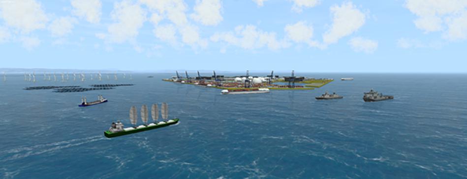
Figure 1. Impression of a combined energy and transport hub.
Most offshore operations which are currently conducted are planned individually due to large differences in structures, availability of support vessels and environmental conditions of the respective sites. In order to find a solution for the growing demand on space and reduce the costs of offshore operations, it is proposed to develop a standardized and cost efficient modular island with low ecological impact. Maximum standardization of the island modules with regard to interfacing edges, connecting technology and mooring systems is envisaged. For this reason, the objective of one of the work packages is to design an optimized standard modular concept for a floating island and to determine the limiting criteria under which different setups of these modules can be used. The designed modules are combinable in any number and combination of applications and thus differ from the TROPOS concept, which is limited to single applications and does not use standardized modules for all purposes.
This article reports the basic design of the envisaged standard modules and their connection and mooring. The design procedure was conducted in three steps. In section “Design considerations,” a participatory design process including all consortium members is introduced. It is employed to identify advantageous combinations of shape, main dimensions, principle of floatation and connections between modules and sea-bed in a preliminary design step. The design options are evaluated by the stakeholders with regard to two sample applications for the island: a logistic hub in the North Sea and an energy hub in the Mediterranean. Then, the preliminary designs are analyzed based on numerical computations with regard to environmental loading they will experience to support the design decision. Finally, the output of the numerical simulations presented in section “Supporting Numerical Work” in combination with the stakeholder input generated in section “Module Design” are combined to derive the final basic design for the modular floater for the Space@Sea island concept.
Design Considerations
The field of variables to be considered in the design of floating offshore structures is vast. Aspects to be considered include the structural integrity, operability of all functionalities, special characteristics of the deployment sites, mooring and more, which already forms a complex design process for stand-alone offshore structures. The complexity is further increased when considering the deployment of multiple connected floating bodies, as the design space is extended by the aspects of connections and inerrability. Due to the novelty of the concept developed in the Space@Sea project, experience regarding the design and installation of scalable, modular floating islands is rare. Considering the large design space and scarcity of related research based knowledge, the design process cannot be holistic and is therefore based on a heuristic approach, which will be presented in the following sections. The design space was grouped in different categories of design considerations: basic dimensions, shape, principle of floatation, and mooring. Options for each design consideration were provided by a review of literature. An evaluation of the suitability of the available options was conducted using a stakeholder involvement process, similar to the MERMAID project (Van den Burg et al., 2016), with a strong focus on the principles of modularity and flexibility. The results of this evaluation were combined to obtain a first concept sketch of the Space@Sea island concept. More background information on stakeholder involvement in a participatory design process can be found in (e.g., Pomeroy and Douvere, 2008; Bjögvinsson et al., 2012; Wilkinson and De Angeli, 2014).
Design Categories
In accordance with the heuristic approach, the design space is split into four major categories, which determine the outline of the overall concept. With regard to the envisaged functionality of the Space@Sea island, each decision in one category will have an impact on the other categories. Therefore, the design procedure is not straightforward. In order to understand the interaction of categories, one may consider a fundamental decision such as whether the main dimensions of a floating body should be of the order of a few meters or a few hundred meters. The choice will significantly influence the applicability of certain principles of floatation, as small objects are typically limited by their responsiveness to waves and the correspondingly experienced accelerations, whereas large floating objects are rather susceptible to structural failure due to large internal strains or slamming. Is shall therefore be said that the choice of categories made here is not absolute, but rather a supporting frame to enhance the design procedure. An overview of the design categories and exemplary subcategories is provided in Figure 2. Considerations regarding the implementation of a top structure were not included in order to maintain a flexible basis for any type of application.
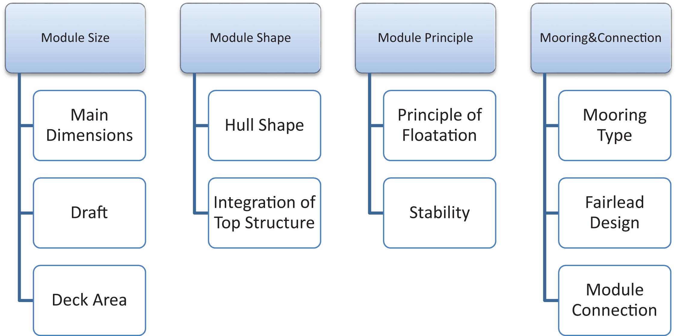
Figure 2. Classification categories of target design for a base module of a modular floating island.
The most central aspects to be covered in an initial design should be based on a functional requirement analysis of the concept. Aquaculture and logistics, accommodation and sustainable energy all have different requirements to provide ideal operational conditions. What they have in common, is that they all require a minimum amount of space for their applications. Classic construction planning, plant layouts and port terminal design provide an idea about the most basic requirements in terms of general dimensions for the respective application. The first category to be evaluated was therefore defined to be Module size, which determines the overall dimensions including, but not limited to draft, edge lengths and deck space.
Closely related to the size is the Module shape, referring to the curvature of the hull lines. This design category is of particular importance due to the modular approach followed by the Space@Sea consortium. Most architectural renderings of modular floating platforms have presented solutions based on equilateral triangular, quadrangular or hexagonal footprints although a thorough analysis of the underlying considerations is not known to the authors. Each shape has advantages and disadvantages when considering e.g., transport and response to waves or on-board logistics and storage and the choice is not straightforward, since it affects the whole design, e.g., since container footprints are quadrangular, a triangular base shape, despite potentially providing advantages in transport operations, will likely require a larger deck area than a quadrangular module to provide the same container storage capacity and thus lead to a non-linear scaling of cost.
In addition to the mere size and shape of the modules, the operability of the functionalities will also depend on environmental conditions and the response of the islands to the resulting external excitation. The installation of the modular islands in an offshore location will expose them to environmental influences such as wind, waves and current. Especially the wave loads on floating structures typically limit the operability due to the wave-induced motion. While the response of the structures to these environmental loads naturally changes with shape and size, the behavior may be significantly altered by choosing a different Module principle. This category of design defines the chosen principle of floatation (barge, semi-submersible, etc.).
The first three design categories serve to establish a solution for multiple freely floating bodies of defined size, shape and principle of floatation. In order to serve their purpose as a modular offshore base for their various applications, the modules need to be designed with some means to enable a general station keeping ability as well as to maintain their relative position. These aspects of design are summarized in the Module mooring category. This category defines the type of reaction force between island and sea bed as well as between multiple island modules.
The overall design is to be composed of individual solutions to the presented categories. Solutions to these four categories and their subcategories are evaluated based on the evaluation criteria presented in the following section.
Evaluation Criteria
In order to classify the potential of possible solutions for the four categories described in section “Evaluation criteria,” a set of evaluation criteria is defined. Based on the experience of the stakeholders involved in the participatory design process, they are asked to penalize designs with shortcomings in the respective design category and promote those which have been proven viable. This serves to identify the most advantageous combinations of basic design considerations without the requirement of a holistic knowledge of the design space.
A key target of the Space@Sea project is to render the multi-use platforms affordable with regard to the envisaged applications. Therefore, the business case of the respective single and combined applications are a focus point of the design procedure. As stated in the introduction of this article, the current non-availability of multi-purpose platform deck space in ocean waters is largely not due to the impossibility of building a solution, but by the challenge to do so at a competitive price compared to on- or near-shore solutions. In order to address this issue, the Cost associated with a specific design choice is established as the most fundamental aspect of design evaluation.
As a second central criterion, the expected impact of a design choice on the Operability of the functionalities has to be assessed. This criterion is related to the efficiency of the platforms considering the various envisaged industrial applications compared to on- or near-shore solutions.
Apart from these two evaluation criteria, slight variations of criteria were used for the respective design categories. Furthermore, each evaluation criterion was considered with a specific weighing factor, to account for the respective impact of this criterion on the design category. Since the direct relation between some design choices and the cost and operability are not as straightforward, the evaluation criteria used for the design categories needed to be further specified to address the characteristics of the respective category in more detail. This becomes evident when for example considering the impact of design choices on transport and installation. The choice of whether the basic module shape should be triangular or rectangular will have significantly less influence on the procedure than the choice of whether the principle dimensions of a body should be a few meters or a few hundred meters in length. Therefore, the evaluation criteria listed in Tables 1–4 were introduced for the different design categories.
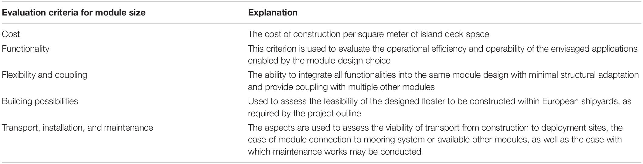
Table 1. Evaluation criteria for module size.
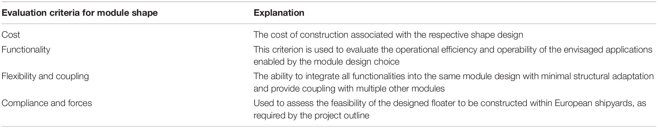
Table 2. Evaluation criteria for module shape.
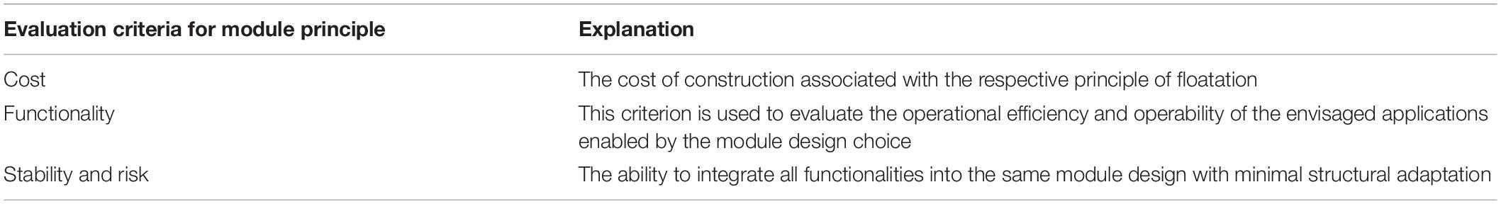
Table 3. Evaluation criteria for module principle.
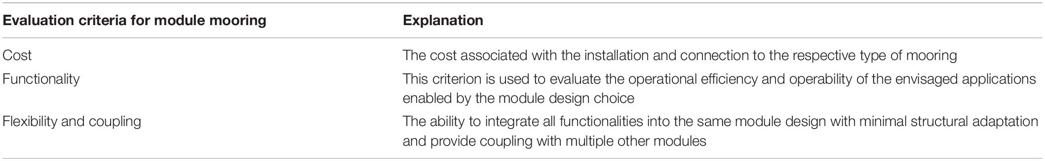
Table 4. Evaluation criteria for module mooring.
Discretization of Design Space
The aim of the design procedure, which is reflected in the definition of the evaluation criteria, is to find a solution that minimizes cost of construction, installation, and maintenance while maximizing operability for all currently envisioned functionalities. A more specific application scenario was drafted to provide guidance for stakeholder decisions during the evaluation process. The sample applications to be considered in the design phases within Space@Sea were given as: the integration of a floating logistic hub located in the North Sea (Figure 3), a hub for renewable energy systems as a basis for floating offshore wind maintenance, located in the Mediterranean Sea (Figure 4) and floating aquaculture production units as well as living quarters for trained crew and untrained residents for both locations.
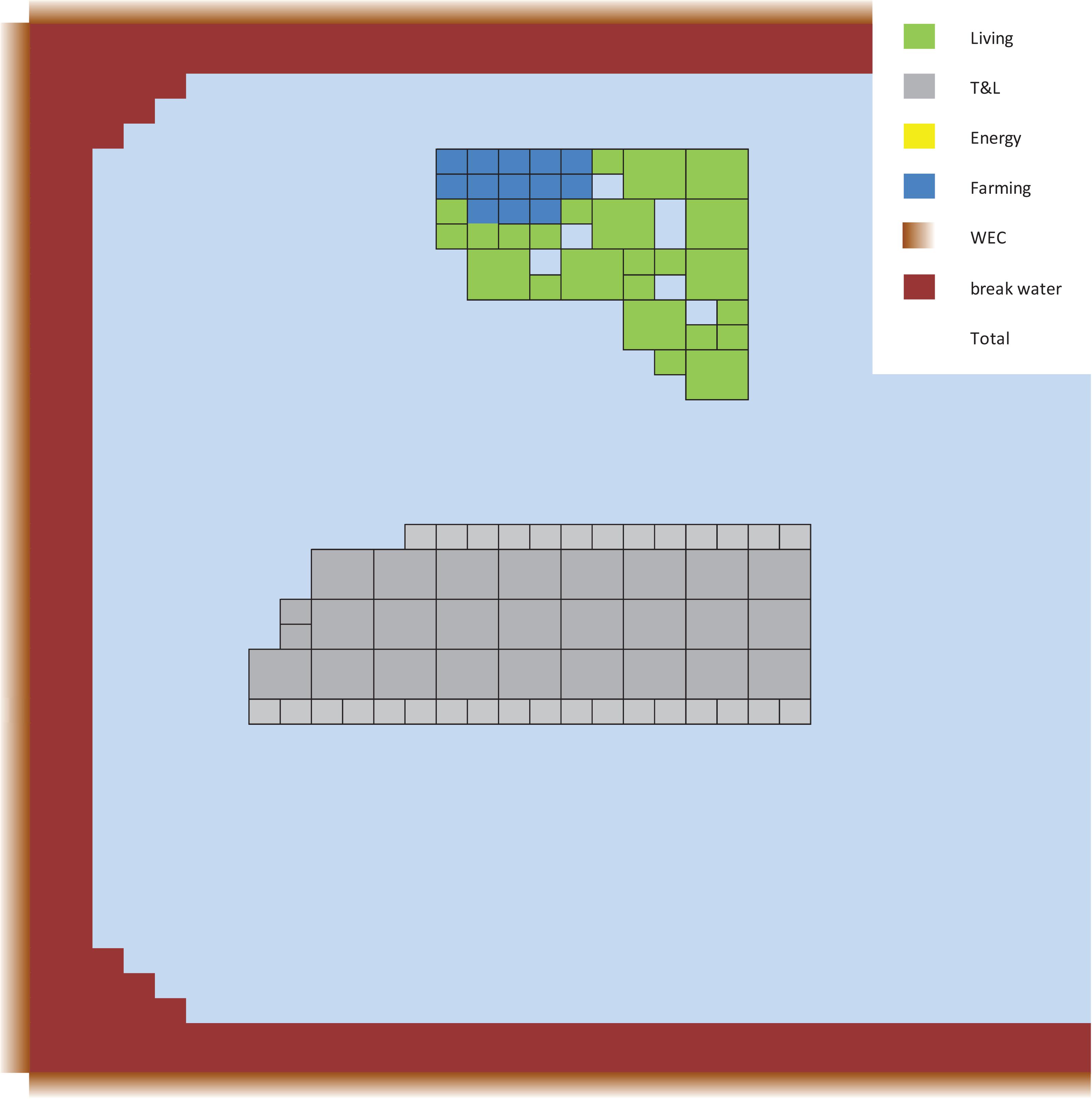
Figure 3. Sample applications to be considered in the design phases within Space@Sea located in the North Sea.
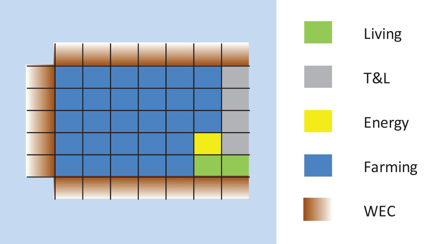
Figure 4. Sample applications to be considered in the design phases within Space@Sea located in the Mediterranean Sea.
As can be seen in the figures, the design for the two deployment site differs considerably. While the high density of transport routes may render the North Sea location economically viable for a transport hub, the local wind and wave climate is rougher than in the Mediterranean Sea. Given that transhipment operations have higher restrictions regarding relative motion of the island modules, breakwater elements are required here. These are fitted with additional wave energy converter (WEC) elements to further dampen wave excitation.
Breakwater elements are not required for the Mediterranean Sea installation site as firstly, the wave climate in the Mediterranean Sea is less extreme than in the North Sea and secondly, the motion limitations for the energy hub and aquafarming modules are less strict than for berthing infrastructure. Sensitive elements of the island such as the accommodation hub are located on the far side of the island with regard to the predominant wave directions (right hand side of Figure 4). As a significant share of wave energy is reflected or dissipated with each row of island elements, wave induced motion is small at these positions.
The functional requirements of the envisioned applications and the desired modularity of the overall island concept are the only initial restrictions of the design space for Space@Sea. In terms of modularity, a simple compact base shape is desirable, since hydrodynamically filigree designs are typically subject to rapid structural failure due to the immense environmental strains inherent with an offshore deployment. Complex extensions to enable form closure based inter-module connections are therefore ruled out. Instead, the shape design is restricted to polygonal shapes, ranging from triangular to circular base areas.
Furthermore, module footprints with edge lengths below 12.5 m and above 200 m were excluded from consideration. Smaller base dimensions would constitute a considerable challenge in terms of installation logistics, e.g., for the assembly of a floating harbor. The maximum size of each module was limited at 200 m due to considerations regarding the availability of building space and towing capacity.
For the principle of floatation, all currently employed solutions in the field of offshore engineering were considered, as only a finite number of solutions is currently available for stationary floating platforms. On overview of the currently employed principles of floatation can be found in (Lehmann et al., 1988).
The design of the mooring concerns the conceptualization of the mooring-module interface, as a dedicated work group within Space@Sea is responsible for the detailed design of the mooring system. The basic design is only concerned with regard to the total number of modules connected to the mooring system, i.e., whether single dedicated modules are connected to the seabed or whether each module has to be moored.
The economic viability of the Space@Sea island can be described by the cost, efficiency and operability of all functionalities. The description of these characteristics as functions of the design categories is expected to result in a highly non-linear target function. For example, each principle of floatation is inherent with a different response behavior of the modules and hereby leads to different environmental limiting criteria for the respective functionality. Therefore, the application of linear optimization functions is deemed unfeasible. Instead, in a first step, discrete points of each design category are evaluated to identify possibly advantageous areas of the design space.
The evaluation of the design categories is done based on surveys gathering individual design scorings from the Space@Sea partners. As a base line for the assignment of a scoring, high level functional requirements were determined for the four applications. These requirements provided by the application task groups and presented in Schay and Otto (2017) are summarized in Table 5. The Ground-Space Index (GSI) refers to the area of the part that is built upon compared to the total area, as depicted in Figure 5.
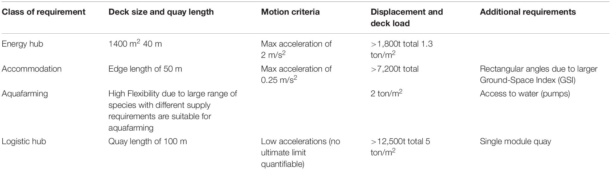
Table 5. Requirements per application task.
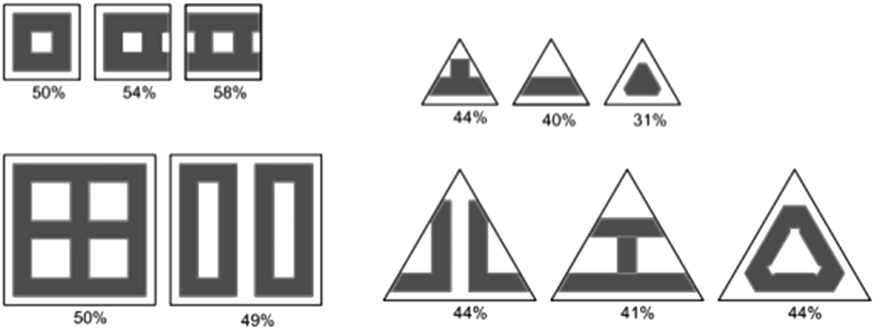
Figure 5. Building footprint compared to platform (GSI) in percent. Taken from Schay and Otto (2017).
Depending on the evaluated design category, criteria are assigned with a weighing factor to include variations in significance of evaluation criteria. This concerns for example the assessment of building possibilities, shown in Table 5. While it is considered easier to find a construction site for modules with an edge length of 12.5 m instead of a total length of 200 m, it is deemed considerably more difficult to berth a 400 m long container vessel to an according number of connected 12.5 m modules while restricting relative motion to a degree that allows competitive operability compared to an onshore harbor. These types of consideration are included in the respective weighing factor. The resulting scoring for each of the design categories presented in section “Design categories” are presented in Tables 6–9. In the scoring, five is maximum scoring and best. One is considered minimum. The weighing criteria add to one. The scoring in the tables represent the average values assigned to the different criteria from the Space@Sea partners. Topic editors with specific experience in the dedicated field evaluated the scoring from the partners.
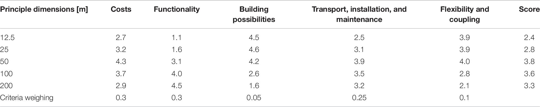
Table 6. Result of module size scoring.
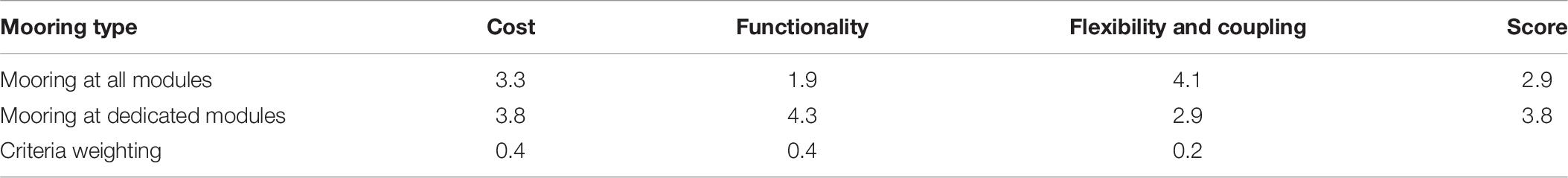
Table 7. Results of mooring option scoring.
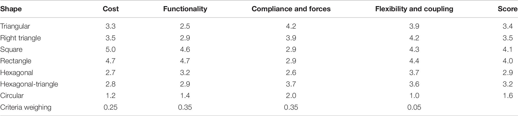
Table 8. Result of module shape scoring.
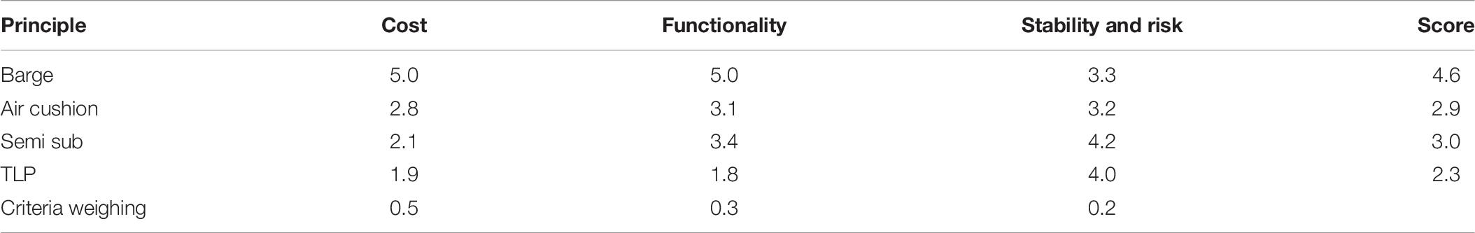
Table 9. Result of module principle scoring.
Results of Preliminary Scoring
The following tables show the results of the preliminary scoring procedure as assigned by the stakeholders. Due to the limited scope of this article, the rationale behind all numbers cannot be discussed in full detail. This is, however, of limited importance as this work is envisaged to highlight the proposed design procedure rather than the results of the evaluation itself. A short summary of general trends is nevertheless given in section “Conclusion of Preliminary Scoring” in order to provide a general classification of the observed trends.
Conclusion of Preliminary Scoring
From Table 6: Result of module size scoring, is can be deduced that a medium sized module provides the best compromise of flexibility and operability. Smaller sized modules are deemed to be significantly hampered with regard to their functionality, while the cost especially associated with building and transport is expected to be high for very large structures. The scoring for the functionality over module size shows that stakeholders expect a strong increase in operability when increasing the basic dimensions from 25 m to 50 m and predict a decreasing gain in operability when further increasing the module size.
The highest scoring in Table 8: Result of module shape scoring can be seen for shapes with rectangular features. While these are expected to be subjected to higher forces in response to environmental loads, this is outweighed by the simpler construction process and advantages in storage and on-board logistics.
A barge type module is the preferred principle of floatation, as can be seen in Table 9: Result of module principle scoring. Due to their large water plane area, the operability of this principle is inferior to TLP or semi-submersible platforms. Nevertheless, they are deemed to provide the more cost efficient solution due to the simplicity of construction, transport, and installation.
Finally, the mooring of dedicated modules was rated as superior to the mooring of each island module. This decision was mainly supported by considerations regarding the cost of installing a mooring point on each module, as well as the inherent negative impact on the availability of deck space for the respective applications.
The result of the preliminary, empirical evaluation of design concepts is used to develop simulation scenarios which serve to provide a quantitative assessment of the platform motion characteristics. Due to the number of possible configurations, exemplary island designs are defined based on the most probable designs as determined by the preliminary scoring. For multi-body systems, an empirical assessment of relative displacement and acceleration is expected to be inconclusive. In order to obtain an understanding of relative and absolute motion amplitudes for the overall island and single modules, numerical computations are conducted. These are presented in the subsequent section.
Supporting Numerical Work
An important choice to make is that between modules with a triangular or square shape. From a hydrodynamic point of view, a triangular shape is preferred. From application point of view, a square-shaped base is the most efficient form. In order to quantify the difference between the two from a hydrodynamic point of view, simulations were performed with the simulation program aNySIM (MARIN, 2019). In the subsequent section, a brief description is given of the simulation tool. For more details, reference is made to MARIN (2019). Section “Description of Simulations” outlines the details of the simulations that were carried out. Here it should be noticed that much more results are obtained then presented. Here, however, only the hinge forces are discussed. These are considered as the main difference between modules with a triangular or square shape. Results of the simulations are given in section “Simulation Results.”
Brief Description of the Simulation Tool
The time-domain simulation program aNySIM can simulate the behavior of multiple floating bodies under the action of combined swell, wind seas, current, and wind. The effect of mooring lines and other mechanical components on the floater motions can also be taken into account. In the simulations, the combined low frequency and wave frequency motions of each body are calculated in six DOF in the time-domain, using a retardation function approach.
The mathematical model is based on a time-step solution of the system of coupled differential equations of motion in which the fluid reaction forces are described with convolution integrals according to the Cummins’ formulation. The program uses linear diffraction data, wave forces, added mass and damping. In this way arbitrary hull forms can be accounted for. Frequency dependent added mass and damping coefficients are transformed into inertia coefficients, retardation functions and response functions. The instantaneous first and second order wave forces can be taken into account. These are the wave forces for the actual position of the body.
The retardation functions as well as the added inertia coefficients are determined using the results of the diffraction calculations. The following forces are included:
• Wind forces
• Current forces
• First order wave forces
• Mean wave drift forces
• Second order wave drift forces
• Viscous damping forces
• Restoring forces of lines
• Fender forces
• Thruster forces
The added mass, damping, wave loads, and wave drift forces are calculated using the linear diffraction theory programs DIFFRAC and DRIFTP. In DIFFRAC/DRIFTP the linearized velocity potential problem is solved using a three-dimensional source distribution technique. The mean wetted part of the vessel hull is approximated by a large number of panel elements. The distribution of source singularities on these panels forms the velocity potential describing the fluid flow around the vessel hull. The pressure distribution on the hull is calculated from the velocity potential. The added mass and damping coefficients, as well as the first order wave forces (DIFFRAC) and second order wave drift forces (DRIFTP) are then determined from the pressure distribution and written to a hydrodynamic database. All calculations in DIFFRAC/DRIFTP are carried out in frequency domain. Non-realistic high wave elevations between multiple floaters or in moon-pools can be suppressed with a free surface lid in DIFFRAC. This lid contains a tuning parameter denoted as epsilon, which reduces the wave elevations in the gap.
Description of Simulations
In order to investigate the differences between hinge forces between an island made up of triangular or square modules, the setups shown in Figure 6 were simulated. Parameters of the modules and the configurations are given in Table 10. The connections between the modules are shown in orange. The triangular modules have a maximum of six hinges at a module. For the square, this number increases to eight. In both cases, the hinges are placed symmetrically and at a distance of 75 m apart. The hinges were modeled as ball joints, allowing free rotations but no translations.
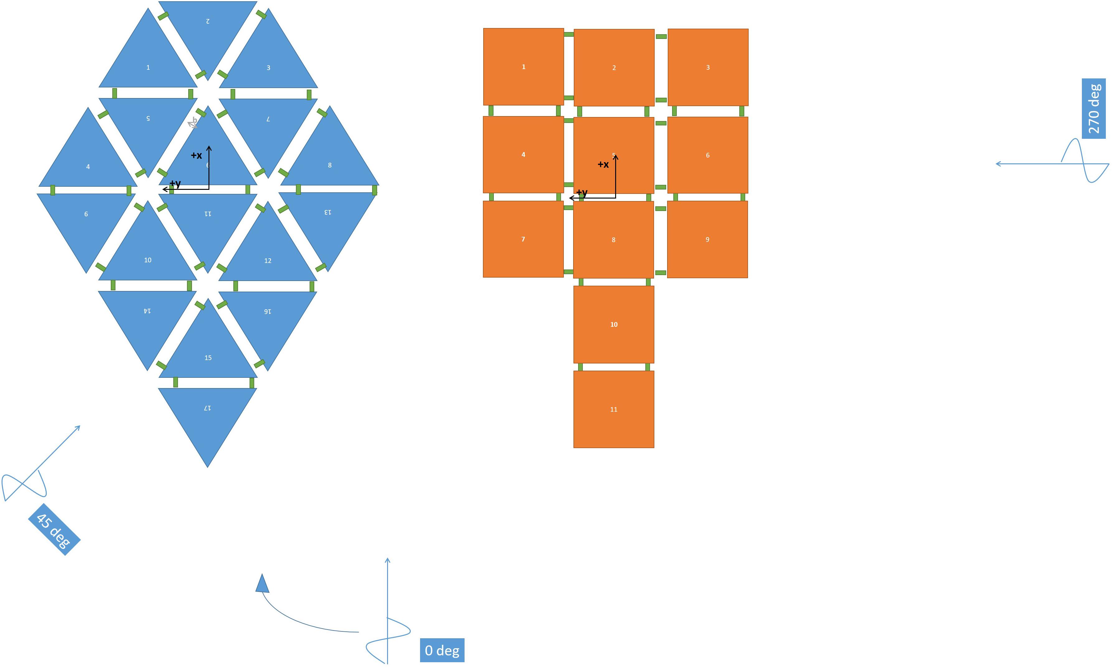
Figure 6. Illustration of island configuration consisting of triangular (left) and square (right) modules.
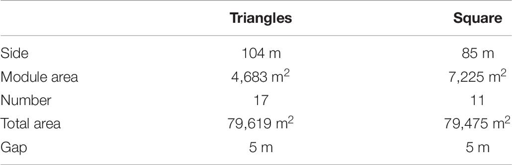
Table 10. Island configuration parameters.
There is no straightforward approach to construct an “equivalent” island made from modules of different shapes. The configurations in Figure 6 are equivalent based on the consideration that the modules can be built in a 90 m wide dock and that the assembly provides 80,000 m2 of deck space. It is recognized that different “equivalent” islands could also be obtained on other considerations. Simulations were done in a JONSWAP sea state with unit significant wave height (1 m) and a range of peak periods and headings. A peakedness parameter of 3.3 was used. Three different spring constants were investigated: 4 × 10⁶ N/m, 4 × 10⁸ N/m, and 4 × 10¹⁰ N/m. The modules were simulated at a draft of 9 m. This corresponds to a mass of 43,205 tons and 66,651 tons for the triangular and square modules, respectively.
A damping value for the lid ε = 0.03 was used. This parameter is tuned such that first order and second order wave drift forces match with model basin experiments. Experience here was gained with side-by-side offloading simulations, see Bunnik (2009). With this approach, a good similarity with the results from model tests has been obtained as shown in Otto et al. (2019).
Simulation Results
Based on the simulations described in the previous section, the significant double amplitude of the relative displacements and hinge forces were derived. From the simulation results it was concluded that a spring stiffness of 4 × 10⁶ N/m is too small leading to very large relative motions. For a spring stiffness of 4 × 10⁸ N/m the relative displacements are significantly smaller. When increasing the spring stiffness to 4 × 10¹⁰ N/m, the relative displacements reduce to less than one millimeter per meter wave height.
The main difference between the two module shapes is that, in general, the hinge forces are often higher for the square modules than is the case for the triangular modules, see Figures 7, 8. These results are valid for a spring stiffness of 4 × 10⁸ N/m. The above will result in more fatigue loading for the connections of the square modules than for the connections of the triangular modules. In terms of the maximum values, the difference is in the same order of magnitude. Although this will likely again translate itself into additional cost for fabrication and maintenance, the difference is at the moment not seen as a reason to choose the triangle over the square, given the advantage of the square shaped base with regard to the higher GSI.
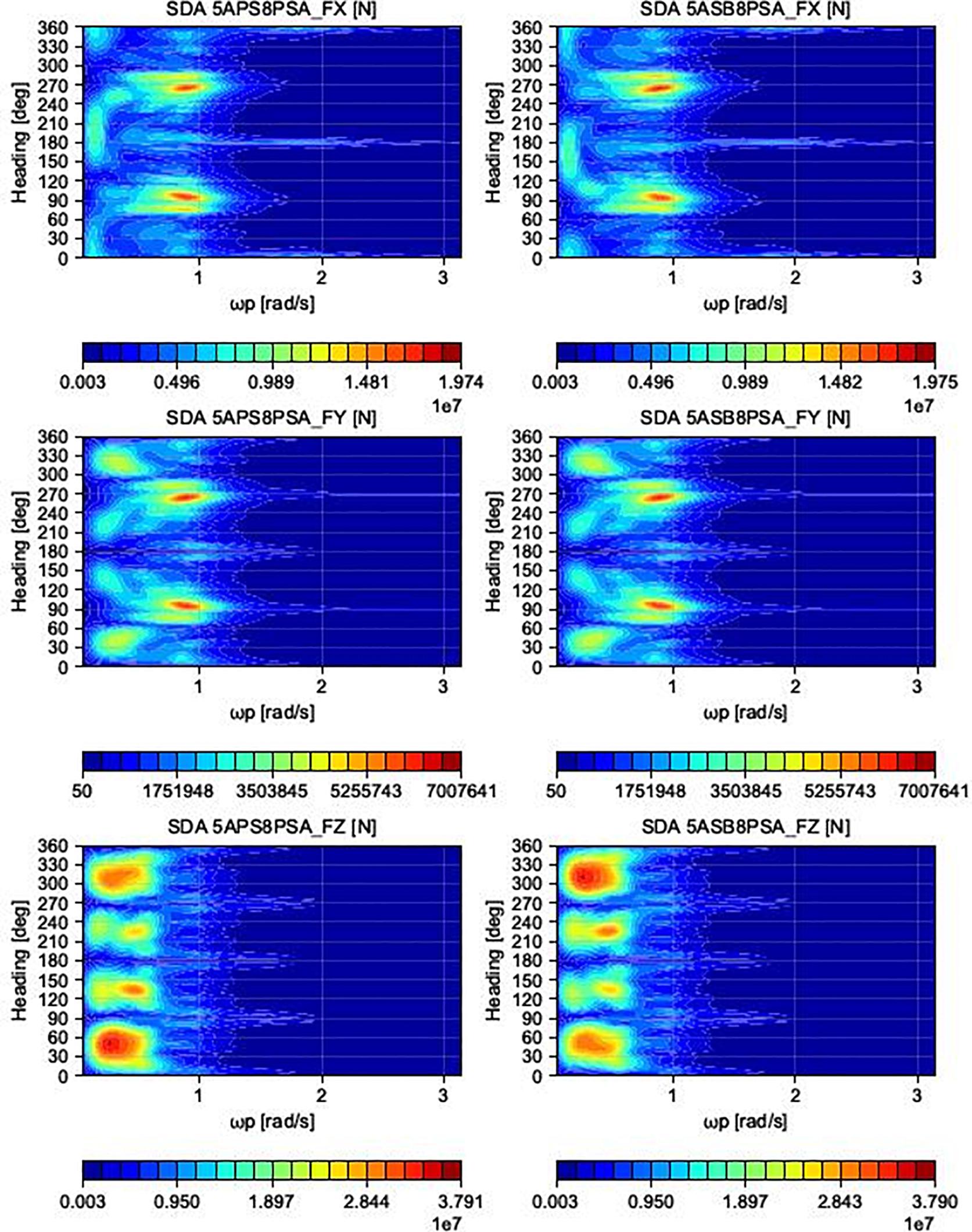
Figure 7. Illustration of hinge forces between an island configurations consisting of square modules for a spring stiffness of 4 × 10⁸ N/m.
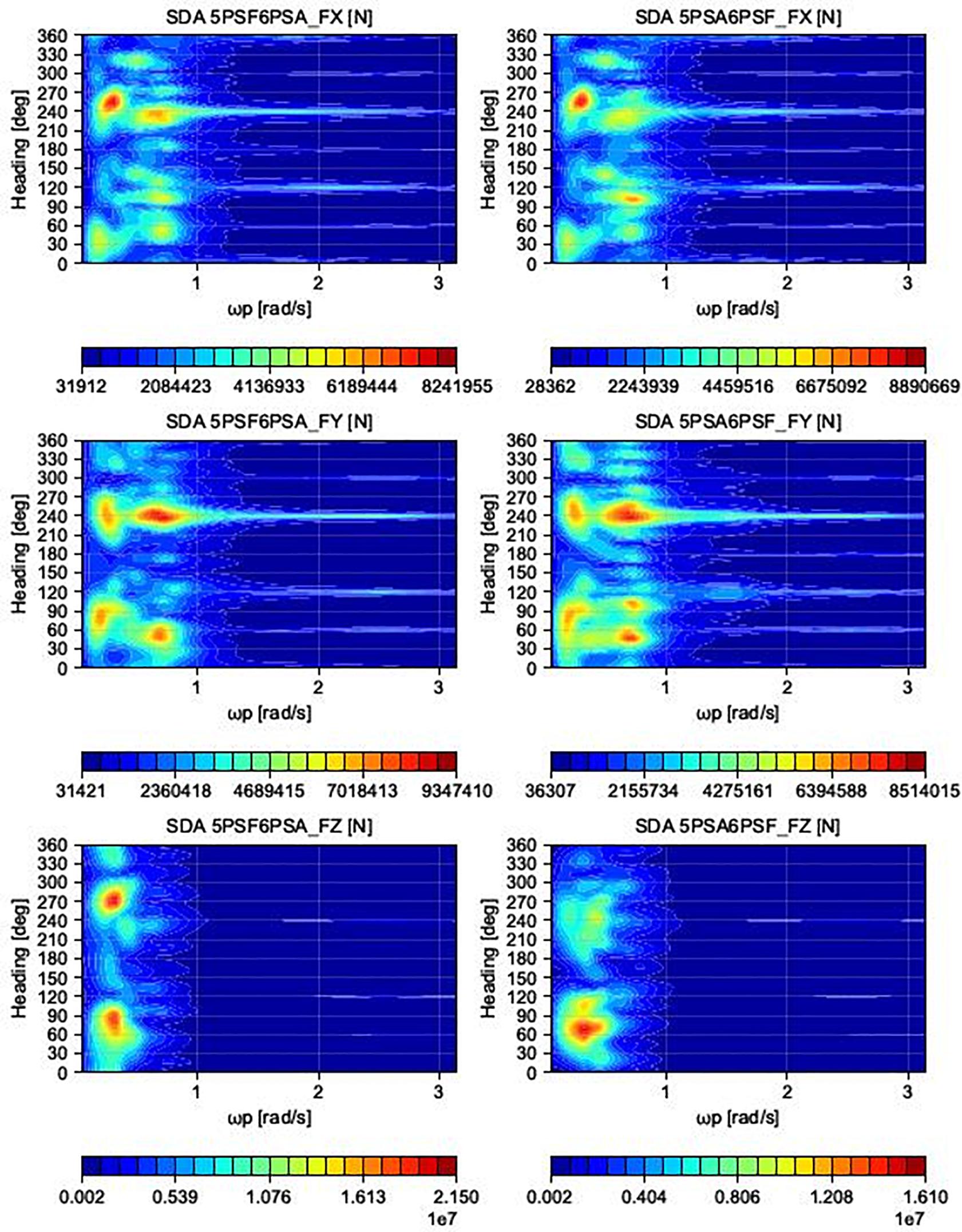
Figure 8. Illustration of hinge forces between an island configurations consisting of triangular modules for a spring stiffness of 4 × 10⁸ N/m.
Module Design
From section “Results of Preliminary Scoring” and Table 6 it is concluded that a model with a principle length of 50 m scores best. As modules with a maximum principle dimension of slightly below 50 m can be built in a large number of places, the main dimension of the modules is defined as 45 m. The choice of this main dimension is largely based on the inherent advantages regarding modularity, building ease and transport and installation effort. Modules of this size may be handled by a single tug and can be built in all larger European shipyards. The deck space and quay length is deemed acceptable for three of the four functionalities, as presented in Schay and Otto (2017). Only the logistic hub would noticeably benefit from an extended quay length, since gantry cranes typically serve 100 m of quay for container vessels. The 45 m module design may, however, be considered a base size able to be coupled to larger modules of two, three, or four times the module size. For the basic modules, a possible reduction in operation efficiency is accepted in exchange for the obtained increase in flexibility. Furthermore, since the scope of the Space@Sea project includes the design of a rigid connection technique for multiple floaters, the shorter quay length may be compensated by rigidly connecting multiple modules. Rigid coupling techniques of floating offshore structures have been proven to operate within acceptable limits for motion sensitive operation e.g., for the Mega-Float project, where a multi-module aircraft runway was deployed in Tokyo Bay (4).
The definition of the module edge length provides the basis for the design of the mooring system. In deep waters, ropes and chains of several 100 m lengths will be attached to the island coming from several directions to provide adequate position keeping ability. Under all circumstances, an entanglement of mooring lines has to be prevented. This would become unavoidable when employing relatively small floater sizes and connecting each module to multiple radially distributed anchor points on the seabed. Consequently, dedicated mooring modules have to form the connection between the Space@Sea island and the sea bottom. A number of additional modules is connected either directly or indirectly to the mooring modules without having an own direct link to the sea bed. This does not imply that the sole purpose of the dedicated modules is the mooring connection. They may serve for other applications as long as these do not interfere with the functionality of the mooring system.
A small base size also plays an important role in the choice of the module base shape. Storage units for containers or foundations for accommodation units provide an optimal GSI when used in combination with rectangular shapes. Both functionalities require orthogonal edges in order to capitalize on 100% of the available deck space. This becomes especially important for small bodies. For polygonal bodies with edges of similar lengths, the relative loss of usable deck space for angles deviating from 90° increases with decreasing overall deck space. In order to illustrate this effect, consider that a single layer of containers is placed on the deck of a square-shaped floater with an edge length of 45 m. The shape of the deck allows the storage of 126TEUs. For an equilateral triangular floater with identical deck space area, 118TEUs may be placed next to each other. If the size of the floater is further reduced, so that only 10TEU can be placed on the square shapes module, the corresponding triangular base area is only able to hold 5TEU (see Figure 9). In this case the loss is 50% whereas in the former case it was only 6%. As medium sized floater modules are envisaged, the improved GSI is still considerable, as was shown earlier for the building footprint of 45 m modules in Figure 5.

Figure 9. Sketch of container storage space for small sized units of different shapes.
A main consideration for a possible preference of triangular over rectangular bodies is the lower block coefficient they provide. Bodies with a lower block coefficient tend to be less susceptible to wave and current forces. However, the results shown in section “Supporting Numerical Work” indicate that despite the high block coefficient of the square shaped bodies, the wave induced relative motion does not significantly exceed the levels also obtained for triangular shaped bodies. Therefore, the advantages with regard to the functionalities are expected to outweigh the minor reduction in relative motion. It should be noted, that for each specific island configuration, the level on relative motion and connection forces will depend on the local environmental conditions and the shape of the island.
The computed relative motion amplitudes shown in section “Supporting Numerical Work” also form the basis for the choice of a barge type floater. As is shown in the simulations, high rotational motion amplitudes of the modules, even within the island, have to be considered for the devised installation sites. Under these conditions, in case of air cushion type modules, the air cushions underneath the modules are likely to lose a significant amount of air. The installation and operation of adequately sizes fans to reshaped the air-cushion is costly. The construction of a large number of such modules is deemed unfeasible, especially since this technique is also inherent with a loss of stability and displacement. The computed relative motion also exposes a disadvantage of the semi-submersible principle. While the reduced water plane area of the surface-piercing columns leads to a reduced response to wave excitation, even for small roll motion amplitudes the relative horizontal displacement of the top structures will be significant due to the large lever arm. As a result, distances between neighboring modules need to include a large safety margin, making joint application of multiple floaters unfeasible. This type of module further suffers from reduced accessibility. As the economic drivers of the Space@Sea concept, namely the logistic and energy hub, require an easy access to the platform for crew and cargo, an efficient transhipment procedure has to be enabled. Current regulation requires the top platforms of semi-submersibles to be positioned several dozen meters above sea level (Lehmann et al., 1988). This complicates any kind of cargo transhipment or crew transfer. The TLP concept was deemed not applicable due to the high cost and the aspect of modularity, which either requires all modules to be connected to the group or require high pre-tension loads on module connections. In contrast, the barge type module is simple to construct, provides a stable platform for all applications, is easily accessible at sea level and requires low installation effort. As a downside, these types of bodies typically experience the highest motion excitation in waves. It is, however, expected that the coupling of multiple such bodies will lead to a reduction of motion excitation.
In conclusion, the basic design for the Space@Sea module is a barge-type structure with a quadratic base shape and an edge length of 45 m. The gap between adjacent floaters may range between 5 m and 10 m and still largely depends on the final design of the inter-module connectors. Single specific modules are employed to moor the island to the sea-bed.
Conclusion and Recommendations
This article presents the conceptual design of a modular floating multi-purpose island. The design of such an island inherently involves interaction within a group with a large range of backgrounds such as engineering, architecture, sociology, climate modeling and more. The heuristic design approach outlined in this article will help future island developers to make a first conceptual design. Four major design considerations were distinguished: module size, module shape, module principle, and module mooring. For each consideration a set of evaluation, criteria were defined. These serve to identify advantageous designs and eliminate impractical considerations. An evaluation of possible design choices was done using a scoring matrix that was filled in by each of the partners within the project. Subject experts for each consideration oversaw the scoring and reasoning behind it.
From the described approach it followed that a barge type principle is the preferred solution for the envisioned functionalities of the Space@Sea project. It is well in line with what is currently build and represents the most easily-built solution. Other principles were investigated but were dismissed because they either required a high increase in installation and building cost or significantly impaired the envisioned functionalities of the island. Although in terms of hydrodynamics a triangular base shape would be preferred, as there is more opportunity in the system to move with the waves, from a practical point of view, for reasons of higher useable floor space, a square modular shape is preferred. While initially, connection forces for a square configuration were deemed significantly higher than for a triangular one, simulations were conducted comparing connection forces between these two configurations. From these, it was concluded that triangles are more favorable in terms of average connection forces. However, maximum forces, which are the key parameter in structural design in an offshore environment, differed little between the two configurations. The choice was made to move forward with square modules.
A small module size is beneficial with respect to the building possibilities as well as the flexibility it offers for the island formations. From a transport and installation perspective, the larger module sizes are easier to handle and with a lower cost. In addition, the larger module size is preferred with respect to the functionality and hydrodynamics. A model with a base size of 45 m can currently be made at a large number of yards across Europe. For larger modules, available yards are limited or new building possibilities need to be created. It was decided to move forward with a 45 m base size. Considered connections are rigid and flexible. Coupling mechanisms to connect four floaters rigidly to form a module with a base size of 90 m will be further investigated.
The most logical choice for mooring of the island is at a limited number of modules, e.g., the outer edges. If all modules will be designed to deal with these mooring loads the modules would have to be overdesigned and would therefore be more expensive. In case of modules with dedicated mooring, there would likely be less structural overdesigning of the modules and it would be much more of a cost-efficient design compared to the case with mooring at all modules. The non-mooring modules and their connection to neighboring modules would still have to be structurally robust, however, since it is anticipated that there could be higher forces in the hinges between modules when mooring lines are grouped in a certain area. In the case of having mooring at dedicated modules, the non-mooring modules would only need to be connected to each other and the mooring connections would be grouped in certain areas; thereby reducing the number of operations required offshore. This also enhances the idea of modularity and flexible increase or decrease of island size.
Author Contributions
Both authors listed have made a substantial, direct, and intellectual contribution to the work and approved it for publication.
Funding
Space@Sea partners received a total of €6,766,793.02 funding from the European Commission as part of the Horizon 2020 research program under grant number 774253. Space@Sea was funded under Research and Innovation call H2020-BG-04-2017.
Conflict of Interest
The authors declare that the research was conducted in the absence of any commercial or financial relationships that could be construed as a potential conflict of interest.
Acknowledgments
The opinions in this document reflect only the author’s view and in no way reflect the European Commission’s opinions. The European Commission is not responsible for any use that may be made of the information it contains.
References
Baird, A. (2011). Floating Container Storage and Transhipment Terminal – An innovative and low-cost port solution. Scotland: Edinburgh Napier University.
Baird, A. J., and Rother, D. (2013). Technical and economic evaluation of the floating container storage and transhipment terminal (FCSTT). Trans. Res. Part C Emer. Technol. 30, 178–192. doi: 10.1016/j.trc.2012.12.013
Bjögvinsson, E., Ehn, P., and Hillgren, P.-A. (2012). Design things and design thinking: contemporary participatory design challenges. Design Issues 28, 101–116. doi: 10.1162/DESI_a_00165
Bunnik, T. (2009). Hydrodynamic analysis for side-by-side offloading. Procs 19th Int Offshore and Polar Engineering Conference. Japan: ISOPE.
Callebaut, V. (2015). “LILYPAD - Floating ecopolis for climate refugees,” in Large Floating Structures, ed. B. T. W. C. M. Wang (Singapore: Springer).
Christensen, E. D., Stuiver, M., Guanche, R., Møhlenberg, F., Schouten, J.-J., Svenstrup Pedersen, O., et al. (2015). Go offshore - Combining food and energy production. Available online at: http://orbit.dtu.dk/en/publications/go-offshore-combining-food-and-energy-production(7bb8c68e-eda9-4235-9059-2534084467da).html (accessed June 02, 2020).
Church, J. A., Clark, P. U., Cazenave, A., Gregory, J. M., Jevrejeva, S., Levermann, A., et al. (2013). Sea-level rise by 2100. Science. 342:1445.
Cosgrave, E. (2017). The future of floating cities – and the realities. Available online at: https://www.bbc.com/future/article/20171128-the-future-of-floating-cities-and-the-realities (accessed May 13, 2020).
Dalton, G., et al. (2015). Unlocking the Potential of Multi-Use of Space and Multi-Use Platforms. Cork: MARIBE Project, University College Cork.
Díaz-Simal, P., Torres-Ortega, S., Del-Jesus, F., and Guanche, R. (2016). Review of multi-use of space and multi-use platform projects. Cantabria: MARIBE Project Partner, Universidad de Cantabria.
FAO (2013). A global assessment of offshore mariculture potential from a spatial perspective. Rome: FAO.
Gentry, R. R., Froehlich, H. E., Grimm, D., Kareiva, P., Parke, M., Rust, M., et al. (2017a). Mapping the global potential for marine aquaculture. Nat. Ecol. Evol. 1, 1317–1324. doi: 10.1038/s41559-017-0257-9
Gentry, R. R., Lester, S. E., Kappel, C. V., White, C., Bell, T. W., Stevens, J., et al. (2017b). Offshore aquaculture: Spatial planning principles for sustainable development. Ecol. Evol. 7, 733–743. doi: 10.1002/ece3.2637
Hart, I. (2015). H2OCEAN - Development of a Wind-Wave Power Open-Sea Platform Equipped for Hydrogen Generation With Support for Multiple Users of Energy. Ansoain: H2Ocean Project, AWL Truepower SL.
Kaji-o’grady, S., and Raisbeck, P. (2005). Prototype cities in the sea. J.Archit. 10, 443–461. doi: 10.1080/13602360500285641
Kim, J., and Morrison, J. R. (2012). Offshore port service concepts: classification and economic feasibility. Flexible Ser. Manufac. J. 24, 214–245. doi: 10.1007/s10696-011-9100-9
Lamas-Pardo, M., Iglesias, G., and Carral, L. (2015). A review of very large floating structures (VLFS) for coastal and offshore uses. Ocean Engin. 109, 677–690. doi: 10.1016/j.oceaneng.2015.09.012
MARIN (2019). aNySim theory documentation, revision 1.4, with aNySIM XMF 13.2.0, (accessed November 29, 2019).
Mauk, B. (2018). A People in Limbo, Many Living Entirely on the Water. Available online at: https://www.nytimes.com/interactive/2018/03/28/magazine/cambodia-persecuted-minority-water-refuge.html (accessed May 13, 2020).
Mcallister, K. R., Taylor, D., Basin, M., Boulevard, M., and Bethesda, W. (1997). Marine Science and Technology Mobile offshore bases. Marine Sci. Technol. 2, 173–181.
Nicholl, R. (2007). European sources for the history of the Sultanate of Brunei in the sixteenth century. Bandar Seri Begawan: Brunei Museums Department.
Ogunlesi, T. (2016). Inside Makoko: danger and ingenuity in the world’s biggest floating slum. Available online at: https://www.theguardian.com/cities/2016/feb/23/makoko-lagos-danger-ingenuity-floating-slum (accessed May 13, 2020).
Otto, W. J., Waals, O. J., Bunnik, T., and Ceneray, C. (2019). On the wave induced motions of a floating mega island. World Confer. Floating Solu. 173–188.
Palo, P. (2005). Mobile offshore base: hydrodynamic advancements and remaining challenges. Marine Struct. 18, 133–147. doi: 10.1016/j.marstruc.2005.07.007
Pomeroy, R., and Douvere, F. (2008). The engagement of stakeholders in the marine spatial planning process. Marine Policy 32, 816–822. doi: 10.1016/j.marpol.2008.03.017
Quevedo, E., Delory, E., Castro, A., Llinás, O., Hernández, J., Consortium, T., et al. (2013). “Multi-use Offshore Platform Configurations in the Scope of the FP7 TROPOS Project”. Bergen: MTS/IEEE OCEANS, 1–7. doi: 10.1109/OCEANS-Bergen.2013.6608061.
Riggs, H. R., Ertekin, R. C., and Mills, T. R. J. (1999). Impact of stiffness on the response of a multimodule mobile offshore base. Int. J. Offshore Polar Engin. 9, 126–133.
Sojo, M., and Auer, G. (2014). MARINA - Marine Renewable Integrated Application Platform- Final Summary Report. Available online at: www.marina-platform.info (accessed June 02, 2020).
Suzuki, H. (2005). Overview of Megafloat: Concept, design criteria, analysis, and design. Marine Struct. 18, 111–132. doi: 10.1016/j.marstruc.2005.07.006
Sweet, W. V., Kopp, R. E., Weaver, C. P., Obeysekera, J., Horton, R. M., Thieler, E. R., et al. (2017). GLOBAL AND REGIONAL SEA LEVEL RISE SCENARIOS FOR THE UNITED STATES. NOAA Technical Report NOS CO-OPS 083. Available online at: https://tidesandcurrents.noaa.gov/publications/techrpt83_Global_and_Regional_SLR_Scenarios_for_the_US_final.pdf. (accessed May 14, 2020).
Tsinker, G. P. (2004). Port Engineering: Planning, Construction, Maintenance, and Security (1st ed.). Hoboken. New Jersey: John Wiley & Sons, Ltd.
Van den Burg, S., Stuiver, M., Norrman, J., Garção, R., Söderqvist, T., Röckmann, C., et al. (2016). Participatory design of multi-use platforms at sea. Sustainability 8, 1–17. doi: 10.3390/su8020127
Van der Wel, M. (2017). The Use of a Floating Quay for Container Terminals. Netherland: Delft University of Technology.
Wang, C. M., and Tay, Z. Y. (2011). Very large floating structures: applications, research and development. Procedia. Engin. 14, 62–72. doi: 10.1016/j.proeng.2011.07.007
Warrick, R., and Oerlemans, J. (2013). Sea level rise. In FAR Climate Change: Scientific Assessment of Climate Change, Vol. 1. Switzerland: IPCC.
Wilkinson, C. R., and De Angeli, A. (2014). Applying user centred and participatory design approaches to commercial product development. Design Stud. 35, 614–631. doi: 10.1016/j.destud.2014.06.001
Keywords: floating islands, conceptual design, heuristic, multi-purpose, Horizon 2020
Citation: Drummen I and Olbert G (2021) Conceptual Design of a Modular Floating Multi-Purpose Island. Front. Mar. Sci. 8:615222. doi: 10.3389/fmars.2021.615222
Received: 08 October 2020; Accepted: 21 January 2021;
Published: 22 February 2021.
Edited by:
Dezhi Ning, Dalian University of Technology, ChinaReviewed by:
Zhiqiang Hu, Newcastle University, United KingdomYong Cheng, Jiangsu University of Science and Technology, China
Junfeng Du, Ocean University of China, China
Copyright © 2021 Drummen and Olbert. This is an open-access article distributed under the terms of the Creative Commons Attribution License (CC BY). The use, distribution or reproduction in other forums is permitted, provided the original author(s) and the copyright owner(s) are credited and that the original publication in this journal is cited, in accordance with accepted academic practice. No use, distribution or reproduction is permitted which does not comply with these terms.
*Correspondence: Ingo Drummen, i.drummen@marin.nl