

Abstract
A comprehensive review paper concerning the geometry, topology, implementation methodology, feeding mechanisms and application domain of wideband and ultrawideband (UWB) antennas for high power applications is presented. Single element antennas, reflector based antennas and array type antennas developed across the globe are taken into account. The antennas considered here are grouped based on their similarity in structure and their performance is compared based on their mode of implementation. This information provides a guidance to the selection of different geometries for various applications especially in the applications pertaining to intentional electromagnetic interference(IEMI). Few antenna models were simulated in CST for the transient response to show their typical transient responses. An exhaustive comparative table is presented with the worldwide designs and some indigenous developments.
Export citation and abstract BibTeX RIS
1. Introduction
Intentional Electromagnetic Interference (IEMI) is a potential threat to the electronic systems and falls broadly in the category of directed energy weapons (DEW) technology [1, 2]. The IEMI environments to disrupt or damage the electronics can be realized through High Power Electromagnetic (HPEM) systems either by repetitive high voltage wide band/ultra-wide band (HV-WB/UWB) transient pulses or by a high power microwave (HPM) narrow band pulse at designated frequency [3, 4]. HPEM systems have been developed across the world for various applications and Prather [5] has surveyed the high power capabilities across the globe. Design and realization of the antennas for the HPEM systems is rather a complex task and it is a challenge, as these huge voltages and/or power demands larger structures that provide enough space to avoid the corona breakdown. However, in order to adapt this technology for IEMI applications these large sizes are impediment. Giri [6] categorized and defined the IEMI environments based on their band ratios, into hypo, meso, sub-hyper and hyper bands as shown in table 1. Accordingly, the antennas that we would be discussing below are with band ratios greater than 1.01 falls in the meso band category and beyond. The HV-WB/UWB antennas transmit and receive very sharp high voltage(∼few hundreds of kV) transient pulses with rise times as low as few pico- seconds and thus are grouped under wide band(WB)/ultra-wide band (UWB) antennas or simply transient antennas for high pulsed power applications. These antennas should not only have the high voltage handling capability but also has to faithfully transmit the high voltage pulse without any distortion. Few such antennas have been discussed by Cadilhon [7] and more elaborately by Giri [8] where he presented an overall picture of the various HPEM radiating systems specific to the band categories that were defined in table 1.
Table 1. Modified bandwidth definitions.
| Band type | Percentage Bandwidth 
| Band ratio br |
|---|---|---|
| Narrowband or hypo band | <1% | <1.01 |
| Moderate or mesoband |

|

|
| Ultra-moderate or Sub-hyper band |

|

|
| Hyper band |

|

|
This article provides the state of the art technologies and topologies adapted in designing the wide band and ultra-wide band antennas for high pulsed power applications. Likewise in any other antenna categorization, these high power ultra-wideband requirements are also grouped into single element antennas, reflector based antennas that are fed by HV feeds and array antennas with medium scale power generators and their performances are accordingly compared. This review has taken into consideration the developments that took place in this field for the past few decades highlighting the critical design features with a motive to aid the engineers and researchers involved in the design of these special antenna structures. Here, the discussion also emphasized regarding the shape, element selection, feeding mechanism, radiation properties, time domain behaviour, spectral occupancy etc and with a brief insight on their advantages and disadvantages.
The paper is primarily organized into 7 sections wherein the general characteristics of WB/UWB transmission and reception characteristics are presented in section 2. Since the knowledge and characterisation of UWB/WB antennas is pre-requisite for understanding and appreciating their performance, an elaborate portion is dedicated in this study. In sections 3–6, the single element antennas, spark gas based antennas, reflector based antennas and array antennas are discussed, sequentially mentioning their shapes, sizes and their time domain behaviour. Finally, in section 7, comments concerning the efficiency of the antennas presented in the paper are outlined with a detailed comparative table.
2. Characteristics of UWB antennas
It is ideal to know the basic transmission and reception properties of high voltage/high power wide band and ultra-wideband (HV/HP- WB/UWB) antennas before going into the actual design and implementation aspects. Salient properties of UWB antennas that were discussed by many researchers are referred here for the benefit of readers. It is a known fact that the size of the antenna depends on the wavelength at the frequency of radiation and is generally satisfied in all the narrow band antenna designs. In case of UWB antennas, where the antennas transmit transient signals, that are spread over a large bandwidth, dominantly in the low frequency regime the size of the antennas would be physically very large if we apply the same logic and would be highly impractical to implement. The primary challenge in design of the WB/UWB antenna is to radiate these low frequency wide band transient signals by a compact structure. Unlike the narrow band antennas which are generally characterised in frequency domain, due to the wide frequency spread of the input signals, it is advisable and even convenient to characterise them in time domain itself and such time domain antenna transmit-receive antenna characterization is brought out by Slivinski in [9]. He extended the discussion in a detailed manner in two more volumes by analysing the time domain near field of pulsed antennas, in particular to a circular disk [10, 11]. Transmission of such impulse like fields and their behaviour over time is mathematically explained in [12] by Baum. Since the antenna parameters in transient radiation cannot be evaluated based on the frequency, it was alternately done by considering the transmission and reception as an linear time invariant(LTI) mode and the respective time domain parameters of the antenna were evaluated [13]. A thesis submitted by Pearson has shown a clear outlook of tackling the antenna radiation in time domain [14] where the behaviour of various radiating structure like apertures, wires and arrays was discussed. Since there were no particular standards to characterize the antenna performance in the time domain and Farr has initiated a proposal [15] with few standards by defining a function that could describe the antenna and its performance in time domain. In this proposal he defined the time domain parameters similar to that of frequency domain. It is to be understood from the above discussion that irrespective of their shape, size and type, the HV/HP- WB/UWB antennas should possess distinct features in radiation and reception of the high voltage transient pulses. Without posing any restrictions on their high voltage handling capability, they should transmit or receive the transient signals with high fidelity. Few notable factors that influence the transient radiation of the WB/UWB antennas are discussed in the following section.
2.1. Effect of antenna on UWB pulse shape
Focusing on the transient response of the WB/UWB antennas is very important prior to the design as it will be a key factor in deciding their suitability in certain applications. The radiated signal characteristics purely depend upon the type of the antenna chosen. Though it is a well-established fact that in most of the WB/UWB antennas, the transmitting mode impulse response is proportional to time derivative of the impulse response in the receiving mode. Referring to this, Rambabu [16] presented the effect of the antenna structure on the UWB pulse in both transmission and reception and a relationship between the transmitted and received pulses for various antennas in the transmission and receive mode had been investigated, as shown in table 2. Inference from [9, 10] is that most of the UWB antennas differentiate the input pulse and receive them as it is. Sorgel [13] analysed this transient radiation/reception, mathematically, and concluded that the parameters like ringing, pulse amplitude and delay that are specifically defined in the time domain are to be investigated and analysed in the time domain only. In this context, Werner [17] has discussed about the basic principles of UWB radiation and highlighted the influence of antenna structures on transmission and also stated that not all antennas are suited for every application.
Table 2. The relationship between input and received pulse forvarious transmitted and received antennas.
| Transmitting antennas | Receiving Antennas | ||||
|---|---|---|---|---|---|
| RDH | VVD | TEM | DSC | BCN | |
| RDH | Diff | diff | diff | diff | Same |
| VVD | Diff | diff | diff | diff | Same |
| TEM | Diff | diff | diff | diff | same |
| DSC | Diff | diff | diff | diff | same |
| BCN | Same | same | same | same | Int |
Legend:RDH = Ridged-Horn antennaVVD = Vivaldi antennaTEM = TEM-Horn antennaDSC = Disc-Cone antennaBCN = Biconical antennaDiff = received signal is the differentiation of input signalSame = received signal is the same as input signalint = received signal is the integration of input signal.
2.2. Dispersion characteristics in UWB antennas
The WB/UWB antenna, or to that matter, any antenna should transmit the input signal with no or minimum distortion. One specific property that effects the transmission and reception quality of these transient antennas is the dispersion. Dispersion is inherently an inevitable property of most of the UWB antennas. It is a property wherein the input pulse waveform is varied as proportional to phase angle of the signal. Debalina [18] investigated this property through a wide variety of UWB antennas including dipoles, spirals, horns, loops, Vivaldi etc under loaded and unloaded conditions. Dispersion distorts the signals to be transmitted so that the waveform gets extended [19] and the main cause for this behaviour is the group delay in the signal. As stated in equation (1), group delay is defined as the rate of change of the phase with respect to angular frequency [20] where ω and θ(ω) are the angular frequency and phase, respectively.

The effect of group delay on the pulsed input signal is shown in figure 1. The dispersed output has a wider duration and longer rise time than the input. This unwanted behaviour can be avoided if we can maintain a constant group delay in the entire frequency band of operation, but this would be an ideal scenario. Hence, a near constant or constant over a specific range of frequencies would effectively reduce this distortion should suffice the design criterion. A quantitative comparison of few UWB antennas based on their dispersive property is shown in table 3. TEM horn, theoretically, is purely, non-dispersive antenna [21] whereas monocone/discone/fat dipole are known to have low dispersion but frequency independent antennas like spiral/sinous/logarithmic antennas exhibit high dispersion. For applications like IEMI, where sharp rise times are mandatory requirement, antennas with low dispersion should be preferred.
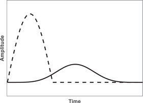
Figure 1. Effect of group delay on the input signal.
Download figure:
Standard image High-resolution imageTable 3. Dispersion properties of few antennas.
| Type of Antenna | Antenna | Dispersion |
|---|---|---|
| Transient Antennas | TEM Horn | No dispersion |
| Vivaldi | Very low | |
| Monocone/Discone | Extremely low | |
| Planar monopole | Very low | |
| Frequency independent antennas | Spiral & sinous | High |
| Logarithmic | High | |
| Broadband antennas | Elliptical dipole | Medium |
| Multimode slot | Medium |
2.3. Figure-of-merit (FoM)
The basic parameters that define the antenna performance such as gain, beam width and radiation pattern are purely frequency domain parameters, and lose their relevance in characterising transient antennas. It is advised to hence carry out the analysis of these antennas in time domain only. There is no difference between the antenna gain of a narrow band antenna either in transmission or reception mode and the property of reciprocity is applicable. Thus a direct extension of antenna gain definition from frequency to time domain goes against reciprocity. Farr & Baum [22], therefore, defined the gain in time domain that is dependent on the property of the input waveform, so gain for the same antenna gain varies for different inputs. Emphatically, it would not be justified to compare the performance of various antennas defined and developed for various applications on the basis of this definition of gain. In such an ambiguous scenario, the figure of merit (FoM), k, defined by Koshelev, appear to be an apt parameter for qualitative comparison of transient antennas. It is defined as the ratio of voltages as in equation (2) whereas the gain definition in frequency domain is the ratio of the power densities.

where Ep is the Electric field at distance r, for an input voltage V.
For example, if a 200 kV peak-to-peak transient signal is fed to the transient antenna and the radiated electric field measured at distance and normalised to 1 m is 100 kV m−1, the FoM is 0.5. This parameter which presents to be more logical and applicable is taken as reference in the following sections to compare the performance of the high power UWB antennas. The typical far field transient response for some of the antennas is simulated in CST Studio and are presented in the respective sections. The input to all these antennas is a double exponential pulse, shown in figure 2, and this signal is very close to the outputs of high voltage generators [23].

Figure 2. Double exponential pulse with 200 ps rise time and 500 ps fall time.
Download figure:
Standard image High-resolution image3. Single element WB/UWB antennas
As mentioned in section 2.2, elementary structures like TEM horn, vivaldi, discone/bicone, dipole etc exhibit very low dispersion properties and are proved to be good examples of the UWB antennas. They are compact and can be easily modified for holding high voltages too. Some of the widely used WB/UWB antennas developed by renowned scientists and researchers across the world are presented in this section. The pictures of the antennas discussed are not shown can be found in the respective references.
3.1. TEM horn antenna
Electromagnetic field distribution of the parallel plate conical transmission lines was discussed by Baum [24] in 1970, but its application to pulse radiation in the present form as TEM horn came out only in early 90 s [21, 25]. The TEM horn antenna has proved itself to be the best of lot in the ultra-wideband category for pulse radiation with very low dispersion and high FoM. It was initially developed for application in short pulse radars, ground penetrating radars and as wideband sensors for electromagnetic compatibility evaluation. The basic TEM horn antenna as illustrated in figure 3(a) consists of two triangular metallic plates, with flared length as, l, hemline length, s. Both the plates are separated by an angle, α and feeding is usually, done by a coaxial transmission line at sharp edge of the conical plates. Changes in these parametric values have considerable effect on its radiation characteristics. Apparently, it offers a very wide band width and for example, an antenna with flare length of 1.5 times the wave length of the lowest frequency has return loss less than −10 dB from 1.5 GHz to 18 GHz. Though Ying [26] in his paper has presented the radiation patterns of the TEM horn, it is appropriate to evaluate the radiation properties of the TEM in time domain only. The simulated far-zone E-field signal at a distance of 1.5 m is shown in figure 3(d).
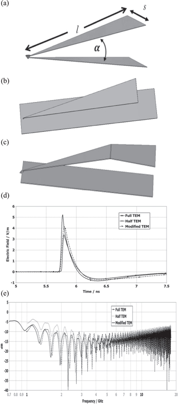
Figure 3. (a) Basic TEM horn antenna. (b) TEM with ground plane. (c) Modified TEM. (d) Simulated radiated pulses for three configurations. (e) Frequency occupancy of three configurations.
Download figure:
Standard image High-resolution imageTo reduce the dimensions of the horn and make it more compact, one of the conical plates is replaced by a ground plate, figure 3(b), but not much difference is observed in their time domain performance except for reduction in the peak value. Kurt [25] proposed a modified design (see figure 3(c)), again for reducing the size of the aperture, by gradually bending the conical plate and aligning it horizontally with the ground plane. The horizontally aligned plate resembles a micro strip configuration with a particular W/h ratio [27] and air as dielectric makes the impedance close to 50ω so that there could be an efficient transmission. This also ensures that impedance from the feed point to the end is constantly maintained and additionally a resistive loading was introduced at the horizontal portion to reduce reflections. The peak radiated electric field is reduced, but the signal parameters like rise time and duration are intact. One advantage with this modification is the performance of the antenna in the lower frequency range has improved, with a good impedance match over those frequencies. However, TEM horn has never been directly used in high voltage applications in this present form but modified versions have been proposed. Umbarker [28] developed a half TEM horn with the flared end curved as shown in figure 4(a). The optimum dimensions are worked out to be as follows:


Though the radius of curvature 'r' should be  for better impedance matching, it demands the size of the antenna to be too large as the wavelength of the lowest frequency component is very large. Hence an appropriate scaling factor is applied to reduce it to a practical value. The electrical length, L, is related to the same wavelength as in equation (3).

Correspondingly, the flare and the tapered angles are related as, as shown in figure 4(b),

It is reported that by feeding this configuration by a 25 ns wide pulse with 5 ns rise time and 113.75 kV peak voltage the far radiated field is about 52 kV m−1 at 1 m, so the FoM would be 0.457.

Figure 4. (a) Schematic of the TEM Horn (Top view). (b) Schematic of the TEM Horn (Top view).
Download figure:
Standard image High-resolution image3.2. Combined antenna
A compact ultra-wideband antenna to radiate picosecond and nanosecond pulses, shown in figure 5(a) was developed by Koshelev [29]. It is a combination of electric and magnetic radiators [30], as shown in figure 5(b). The portion marked 1 is an electric radiator in the form of a TEM horn and 2 is active and 3, passive magnetic dipoles. By varying the position of the plate between 2 and 3, the size of the magnetic dipoles would change and it has a direct effect on the radiation. The energetic efficiency, defined as the ratio of the radiated energy to the input generator energy, changes with the perimeter of this plate. Section 4, is a connection to the 50Ω feeder. The overall dimensions of the antenna depends on the length of the pulse to be transmitted, ≈cτ/2, where τ is pulse width and c, the velocity of light. This antenna is fed through a high voltage 50Ω connector. The typical radiated waveform(simulated) of a combined antenna is shown in figure 5(c). These types of antennas are particularly designed to operate over a wide bandwidth, with a band ratio of more than 7. which makes them a perfect antenna choice for transmission of sharp rise time pulses. The energetic efficiency goes to as high as 0.9 for the bipolar pulse input and the antenna power efficiency is almost 0.5, a notable value for the horn type radiators. The 50 ohm connector and limited gap between electric and magnetic dipoles may pose restrictions for higher voltage applications. However, by enclosing the antenna in a thin walled polyethylene enclosure filled with pressurized such as SF6, the voltages can go the order of hundreds of kV. The form-factor reported in [29] is approximately 0.78 for a single antenna with an input voltage of 60–70 kV. It also proved to be a good example of the non-dispersive antennas as its phase variation over the entire band of operation is less than 0.2 radians.
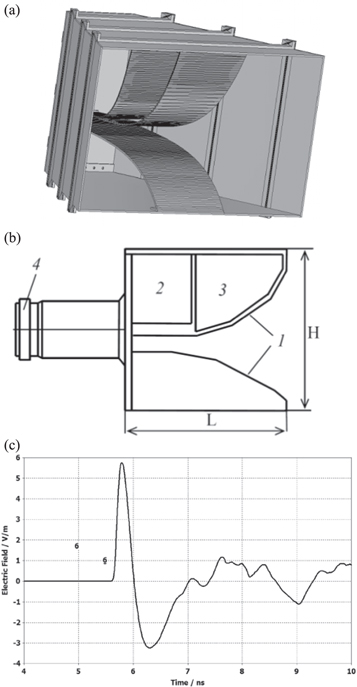
Figure 5. (a) Combined antenna with electric and magnetic dipoles. (b) Schematic showing the electric and magnetic dipoles. (c) Typical radiated waveform (simulated) of a combined antenna.
Download figure:
Standard image High-resolution image3.3. Sub miniature antenna
One more design similar to combined antenna was developed in the recent years that could radiate sharp bipolar pulses [31]. This coaxial fed antenna is compact in size and the dimensions are defined in terms of the wavelength in contrary to the other time domain antennas. The antenna has nearly a decade bandwidth, from 0.2 to 2 GHz. This antenna also has magnetic and electric dipoles similar to that of combined antenna that was discussed in the previous section. One observation in the above reference is that a bipolar signal is given to the antenna at the coaxial end. Since a coaxial accepts only unipolar signal, the full energy of the input might have not been transferred to the antenna, so a balun should have been placed prior to the coaxial end to feed the differential voltage. The schematic is shown in figure 6. Since the input impedance is mainly dependent on transition from coaxial to parallel plates a smooth transition to gradually match the input impedance is incorporated. The conical part was truncated to increase the radiation in the frontal direction and make it more directional. The input peak-to-peak voltage is 131 kV, for which the FoM would be nearly 1.

Figure 6. Schematic of the sub miniature antenna.
Download figure:
Standard image High-resolution image3.4. High power helical antenna
In applications, where, a circularly polarized radiation is a requirement, the helical antennas with their simple design, proves to be the best option and APELC developed [32] a shock excited helical antenna for transmitting pulse waveform. The design of the helix, as in figure 7(a) is taken from the design parameters given by [33], such as the circumference of the helix, number of turns and spacing between them. However, to make it compatible to the high power applications, certain modifications have been proposed by Mayes. The complete structure has been divided in to four parts as shown in figure 7(b). Section A is to be designed so as to match the impedance of the high power source whereas part B is gradually bent from the straight portion to the helical section to avoid impedance mismatch. At C, the quarter wave section takes the turn taken along the ground plane, which acts as an impedance transformer and part D is a regular helix. A helical antenna implemented with the above conditions, by Mayes [34] has yielded an FoM of about 0.875. The radiated waveform is typically a damped sinusoid signal shown in figure 7(c) for the double exponential input. Parallelly, Giri also proposed and constructed the helical antenna [35], that could be directly fed by high voltage switched oscillator [36]. The input voltage as per [35] is about 35 kV onto the antenna and the corresponding radiated electric field at 1 m is 15 kV m−1 in one plane, so the effective circular polarized E-field would be 21.2 kV m−1. The FoM, would then be 0.606. In addition to these, Giri also pointed out, that the Q factor of the helical antenna has a proportional effect on the radiated E-field. The response for the higher Q is similar to that of a response of the resonant circuit with high Q, with a low damping factor.
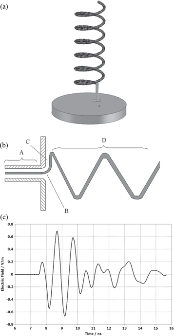
Figure 7. (a) Classical helical antenna. (b) Modified helix for high power applications. (c) Typical damped sinusoid radiation from a helical antenna.
Download figure:
Standard image High-resolution image4. Spark gap integrated antennas
In the process of developing compact and high efficient antennas, researchers started working on the spark gap switch integrated into very common antenna elements like dipoles and bicones. These antennas can be a good choice for applications where size matters. The principle of operation in these antennas is as follows: 'The spark gap is charged to few hundreds of kV and the maximum voltage to which the gap can be charged depends on the dielectric strength of medium in which the gap is placed. When the voltage across the gap is exceeded beyond the breakdown strength of respective medium, electric discharge occurs and in the process, an electromagnetic pulse, in general, a damped sinusoid is radiated'. When the voltage exceeds the breakdown voltage of the gap, it acts like LC oscillator. The charging energy is, hence, converted into oscillating currents that are radiated by the antennas. The switch can, therefore, be represented as an RLC circuit with the resistance equal to the discharge arc resistance, which is less than 1 ohm [37]. The prime advantage of these high power antennas is that, they can hold very high voltages because the voltage handling capability simply depends on the gap distance and the medium in which the gap is placed. But large gaps increase rise times, which means the signal is dispersed. So placing the spark gap in a high dielectric strength medium is a viable option rather than increasing the gap distance. Gases, such as, pressurized SF6, nitrogen, hydrogen are generally used to increase the dielectric strength of the gap whereas in some applications, liquid dielectrics like transformer oil, ethylene glycol or even water are also used. Few such antennas developed by various researchers are presented in the following section.
4.1. Biconical antenna
Conical structures are good examples of wideband antennas [38] and their transient behaviour is given by Harrison [39]. Biconical antennas integrated with spark gap produces a sharp rise time wide band signals h and can hold very high voltages even to a few MV. The concept is shown is shown in figure 8(a) and the typical radiated signal is shown in figure 8(b). The shape of the electrode tip is very sharp as shown in this case, however, profiles like hemi spherical or flat, are generally selected so as to have a uniform electric field at the electrode. In 2002, Kevin [40] developed a biconical antenna fed by a spark gap switch. It consists of two cones separated by a spark gap of 7 mm. The spark gap is made of two brass electrodes of 25 mm diameter and is filled with SF6 gas at 5 atm pressure. Its schematic and the structural features are shown in figure 9. In order to avoid external discharges, the whole antenna is placed in a non-metallic container filled with ethylene glycol and 1 m long rods were attached to the conical sections to increase the radiation resistance. The measurements were carried for 200 kV input voltage and the electric field values were recorded at various distances from the source. With the ground bounce effects taken into consideration, FoM of about 0.3 is claimed.
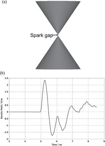
Figure 8. (a) Biconical antenna integrated with a spark gap. (b)Typical transient radiated signal form a spark gap integrated biconical antenna.
Download figure:
Standard image High-resolution image
Figure 9. Schematic of the Compact bi-conical with integrated source with enlarged spark gap portion.
Download figure:
Standard image High-resolution image4.2. Dipole antenna
Very recently, the development and utilization of dipole antennas with integrated spark gap for high power applications have taken precedence over other configurations due to their ease in implementation. Of these, the meso-band pulse radiator by Lee [41] is a notable development in the band ratio is between 1.1 and 3. Hence, this design may not be considered as UWB, but comfortably be called as wide band. The antenna consists of two fat dipoles separated by a spark gap, as shown in figure 10(a). The spark gap is viewed as an RLC circuit as shown in figure 10(b). The resonant frequency of the spark gap is thus calculated as

where  and
and  are the equivalent inductance and capacitance as described in [42, 43].

Figure 10. (a) Dipole with spark gap switch. (b) Electrical equivalent of dipole antenna. (c) Sparkgap integrated dipole antenna devloped by us. (d) Typical radiated signal from a dipole antenna. (e) Cross section view of the switch part.
Download figure:
Standard image High-resolution imageThe dipole exhibits a significant property called as double resonance was observed and presented by Lee where the double resonant peaks changes with the dimensions of the dipole. For a 60 kV input to the antenna the received E-field normalised to 1 m is 28.76 kV m−1, which decides the FoM to be 0.48, a value comparable to the similar configurations in the literature. By examining the received signal the rise time is estimated to be in the order of 2–3 ns. The typical transient radiated signal of a dipole antenna is shown in figure 10(d) The spark gap integrated dipole antenna developed by us is shown in figure 10(c). The whole antenna is placed in a sealed perspex contained that can be filled with oil to avoid external discharges. Another similar antenna was designed and developed by Ryu [44], where FoM is improved substantially when compared to the previous version. The antenna named by the author as integrated antenna source(IAS) is made very compact in size with overall length as 400 mm and 250 mm diameter. The aluminium electrodes separated by 3 mm gap are placed in a reinforced casing to hold the high pressure. The cross section of the antenna is shown in Fig are shown in figure 10(e). The electrodes are carefully modified to avoid the sharp edges that would lead to unnecessary discharges.
The antenna was subjected to a high voltage of 470 kV and reported a normalized received E-field at 1 m as 322 kV m−1 with a sharp rise time of 380 ps. The FoM is around 0.68 for the dipole alone, larger compared to the antenna discussed in section 4.2.
5. Reflector based antennas
As discussed, and shown in previous sections, the figure of merit is invariably low value for all the single element antennas. Increasing the input voltage proportionally is not a viable remedy, as higher the voltage, more are the problems. FoM would still be the same value, only the radiated field increases proportional to the input. The best practical way to increase the FoM would be to make them more directional rather than radiating energy in omni direction. To accomplish this, the aperture of the horn type antennas can be increased, but definitely there would be a size beyond which it cannot be increased as the directivity of horn antennas reduce by doing so [45]. Whereas in spark gap integrated antennas, increase in dimensions of the biconical or dipole elements would shift the resonance frequency to lower side, but again, increase in length beyond certain value will not have considerable advantage in its FoM. One possible and easier way is to feed a passive reflector by the spark gap integrated antennas and make it more directional thereby increasing the FoM. This configuration increases the gain and sharpen the beam width. In ground-based applications where sizes can be compromised, the reflector-based antennas are preferable. The technology is not so different from what has been discussed in the previous sections, but a decent care needs to be taken in its construction and feeding. The transient radiation from reflector antennas is explained in [46] where the near and far field formulas have been formulated based on the pulse radiating characteristics. Few such antennas are discussed in the next sections.
5.1. Impulse radiating antenna (IRA)
Carl E. Baum and Everest Farr were the pioneers to develop the impulse radiating antenna(IRA) with a parabolic reflector [47–49]. It was initially developed to address the requirements of transient radars for transmitting huge amount of pulsed energy over long distances. IRA is basically, a combination of a parabolic reflector and conical/coplanar TEM transmission line feed arms [50] and the feeding is through a switch placed between the pair of TEM plates as shown in Fig11a. The basic concept of an impulse radiating antenna is that, when a step rising waveform is given as input to the TEM feed, it produces a similar step-rising field as a plane wave on the antenna aperture which in turn radiates an impulse at far field in bore sight. Like any other parabolic antenna, the feed is placed at the focus and the other ends of the TEM structure are terminated on to the reflector through resistance. The plane wave in a coaxial wave guide is converted to a spherical wave which is then launched on to the conical feeds. The properties and features of the IRA have been extensively investigated for many years [51–53]. Low voltage IRA antenna available in our lab is shown in figure 11(c). The TEM feed, is fed by a spark gap housed in a high dielectric strength medium, either oil or pressurized gas to hold high voltages and the maximum voltage that could be held by the spark gap depends on the gap distance and the dielectric medium. The layout of the switch in particular is shown in figure 11(b). The voltage is, thus, launched onto the coplanar feed arms that produces a planar field on the aperture of the reflector. The result is an impulse like wave from with finite rise and fall times and a typical such radiated signal from an IRA is shown in figure 11(d). Though gain is a concept governed by the frequency of operation, in order to qualify the time domain reflector antennas quantitatively, Giri in [54], has defined the gain of IRA as

where the geometric factor, fg
is defined as  The other factors are defined as follows:
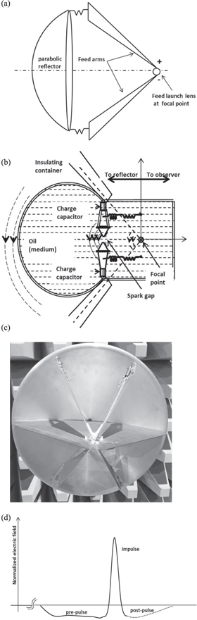
Figure 11. (a) Schematic of the impulse radiating antenna (IRA). (b) Construction details of the feed portion of IRA. (c) Picture of low voltage IRA antenna available in our lab. (d) Typical radiated signal of IRA showing pre and post pulse.
Download figure:
Standard image High-resolution imageZc = characteristic impedance of the IRA
Z0 = free space impedance, 377Ω
ha = effective height of the reflector
c = velocity of light
tm = rise time of the radiated waveform
In general, the characteristic impedance of the planar conical plates from the feed to the reflector is about 400Ω for two arm IRA [51], but varies in other configurations depending on the number of arms. By varying Zc and fg, the FoM for the respective configuration can be calculated as shown in table 4. EM simulation of the IRA was carried out by Sidhartha [55] in CST-MS and all the basic parameters of antenna like directivity, beamwidth, VSWR etc were calculated. Giri [51] designed and fabricated a full IRA with 3.66 m with the feed placed at 1.21 m from the from the apex of the reflector is shown in. The 200 input TEM structure was fed by a differential voltage of ±60 kV. The radiated far field was measured as 4.2 kV m−1 at 305 m. As mentioned above, the Half IRA (HIRA), which is more prominent among other configurations, is presented in detail in the next section.
Table 4. IRA parameters for various configurations.
| Type of IRA | Peak applied voltage (volts) | Geometrical factor, 
| Effective height, ha (m) |
 (volts) (volts) |
|---|---|---|---|---|
| 2-arm full IRA | Differential |

|

|

|
| VP (±VP/2) | ||||
| 4-arm full IRA | Differential |

|

|

|
| VP (±VP/2) | ||||
| 2-arm half IRA | Single-ended |

|

|

|
| VP | ||||
| 1-arm half IRA | Single-ended |

|

|

|
| VP |
5.2. Half impulse radiating antenna (HIRA)
Over many years, high voltage generators that produce powers in the order of GWs and high repetition rates (even tens of kHz) are developed by many agencies but most of these are single ended with a coaxial termination. It is seen from the above table that an IRA needs only a differential input and since converting these high valued single ended signal to a differential voltage is a complex task that led to the development of a half IRA [56]. The schematic of HIRA showing the position of the lens is can be seen in figure 12(a). However, the difficulty is in converting the plane wave into a spherical wave and launching onto the feed arms and this is accomplished by placing a feed point lens at the focus of the reflector [57]. The dielectric feed point lens, hence, has to be designed to hold these high voltages. The feed point lens is made of a material with a dielectric constant required enough to bend the rays from the coaxial end onto the two arms. The permittivity of the lens material in most cases is between 3.5 to 4.5 and the lower end of the lens is filled with oil with a relative permittivity of about 2.3. As long as the conductor is inside the oil, there will not be any breakdown but the problem arises at the junction where the conductor comes out of the lens and the wave is launched onto the feed arms. The complexity increases with increase in voltage, may be because of which compact HIRAs could not developed for voltages in the order of 200 kV and beyond. One of the commercially available HIRA is shown in figure 12(b). Typical radiated signal from the HIRA shown in figure 12(b) is given in figure 12(c) along with the simulated signal in the FDTD solver. Ruling out all these restrictions, Carl E Baum, the inventor of IRA has developed and demonstrated a HIRA, called JOLT [58], for 1MV, 600 Hz input and achieved r*Er as high as 5.3MV and a rise time of 80 ps. These results have remained to be reference for the further designs and developments where FoM is, 5.3, for the reflector size of around 3 m. The pulser and the feed point lens are specially designed in this case with hydrogen switches for achieving high PRF. These are, in fact, the pioneering developments for the transmission of impulse like signals and have been extensively reported with different variations and applications.

Figure 12. (a) Schematic of Half IRA with feed point lens. (b) Commercially available HIRA. (c) Typical transient radiated signal from HIRA.
Download figure:
Standard image High-resolution image5.3. Discone fed reflector antennas
As discussed in section 4, the spark-gap based antennas are very compact and simple in design. Be it a conical antenna or a dipole, they are well suited to hold very high voltages and high radiated electric fields can be achieved by these designs for increased input voltages. The voltage handling capacity can be increased by placing the gap in a medium of high dielectric strength with higher pressures but the availability of such high dielectric materials is limited. Second option is to increase the gap between electrodes, but more the gap, poor is the rise time. In order to achieve a large FoM, with such type of antennas, they are used as feeds to large parabolic reflectors and by doing this, the effective FoM can be increased by many times. One such design was proposed by Baryshevsky [59] in which a discone antenna was placed as feed for the 1.6 m reflector. Though the paper talks more about the design and development of the high power Marx generator, a novel antenna configuration to transmit the high power UWB pulses is introduced. It is a well-known fact that a discone antenna (monocone-disk combination), schematic shown in figure 13(a), is otherwise widely used for it UWB properties [60]. It has wide range of applications including passive radars, ground penetration radars etc, however, adopting it for high voltage applications is a new concept. One such antenna shown in figure 13(b) was realized by us to study its properties. The spark gap is integrated into the discone antenna and is placed in oil, a high dielectric strength medium [61], to hold high voltages. A mechanism is provided to adjust the gap between the electrodes. It works on the self-breakdown phenomena like any other spark gap antennas. The radiated signal as per [59] is around 4 kV m−1, at 30 meters with input of 300 kV(not clearly mentioned), so the FoM would be 0.4. But our indigenous antenna, figure 13(b), has shown better results with 60 cm reflector and 200 kV input. Here the discone is placed in an acetal co-polymer container filled with oil. The transient radiated signal measured at 4 m shown in figure 13(d) and the FoM is 1.2.
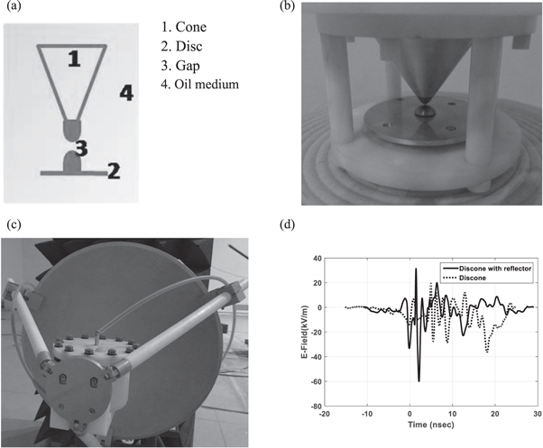
Figure 13. (a) Schematic of the discone configuration for high voltage pulse radiation. (b) Discone antenna with a mechanism to adjust the gap. (c) Discone fed reflector antenna developed in our lab. (d) Transient radiation( measured) response of discone fed reflector compared to discone alone.
Download figure:
Standard image High-resolution image5.4. Dipole fed reflector antennas
Similarly, feeding a passive reflector with a dipole element is also a widely used topology. was proposed by Jiheon [62] with his previously developed IAS antennas as feed. Here a parabolic reflector of 1.5 m which is nearly 10times more than the size of the dipole is considered and the dipole is placed at the optimized focal point of the reflector for maximum efficiency radiation. It is a non-transmission line design unlike IRA and all the complications that would arise due to the transmission lines and the terminating resistors are eliminated. The size of the feed, that is IAS antennas here, can also be reduced to half as the FoM is dependent on the aperture of the reflector, not on the size of the feed. Jiheon has discussed the parabolic reflector analysis in detail and has supported the theory with numerical and practical results. The monopoles are separated by a spark gap of 2 mm and is placed in a dielectric casing filled with 70 atm nitrogen gas. With the feed voltage as 316 kV, a radiated field of about 43 kV m−1 at 40 m is received. From these values the gain/FoM is calculated to be about 5.43. This configuration has proved to be highly suitable option for very high voltage applications. Similar dipole fed reflector antenna is available with us is shown in figure 14(a). The feed is a dipole with a hydrogen filled spark gap integrated into it. The radiated signals for 200 kV input of the dipole with and without reflector are shown in figure 14(b). The FoM with reflector is almost 4.0.

Figure 14. (a) Dipole fed reflector antenna implemented by us. (b) Transient radiation of dipole antenna with and without reflector.
Download figure:
Standard image High-resolution image6. Array antennas
Ultimately, the requirement of any wide band antenna is to transmit the pulse without distortion. The rise time and durations of the pulse should remain unaltered. Applications like DEWs, demand huge electric fields at a faraway distance, i.e., large k, defined in equation (3). The two possibilities that were basically possible were to increase the source power, so that the radiated electric field is proportionally high or to increase the aperture of the radiating antenna and make it highly directional and increase the radiating E-field. Increasing the source power unlimitedly is not a fruitful solution as generation of higher powers and feeding the antenna poses higher problems. The high voltage electric discharges would be then a common hurdle and unavoidable, particularly at the interface of the source and antenna. Switching to the other possibility, selecting large aperture antennas like huge reflectors or horns would be inconvenient to be used and restrict their portability. In this curtailed conditions, one possible solution that engineers could think of is using array antennas. But here, the concept and implementation of UWB arrays is different from that of narrow band (NB) arrays. In UWB radiation, the radiated waveform varies both in space and time, unlike the NB arrays that varies in space only. Two viable configurations are 1generator/N antennas or N generators/ N antennas, where the former option divides the power using power divider and the divided voltage is fed to the antennas. In the latter option, N relatively smaller power generators feed N antennas and the energy is combined in space. The concept of transient arrays, with an ability to electronically scan is proposed by Baum [63]. The intuitive impediment in the transient arrays is the distortion caused due to jitter. Since most of the array elements are spark gap switch based antennas, the variations on the time of arrival of individual signals at the far-off plane would lead to reduction in the peak value withal extending the rise time. However, researches have contributed to overcome this by developing high accurate photo conductive switch based antennas, that would even fire with an accuracy of 10 ps [64, 65]. Nevertheless, enormous developmental activities have taken place in developing the transient array antennas with primary elements such as spark gap based antennas, TEM horn, combined antennas, high power helices etc and a few such developmental activities are brought in the following section.
6.1. Multi element combine array
As first of its kind, the transient array that could primarily be considered is the array antenna developed by Kosholev [66–68] with combined antennas as the primary element. A 4 × 4 array with combined antenna as the feed element was developed, as an extension to his work that was discussed in section 3.2. The concept is shown in figure 15(a). The typical transient radiation compared with the single element to a 2 × 2 array is shown in figure 15(b). To describe the array developed by Koshelv, it is fed from a single source by a nitrogen spark gap switch through the coaxial cables and the input power is divided among the 1 ft × 1 ft × 1 ft combined antennas(see section 3.2) proportionally. The aperture of the array is approximately 120 cm × 120 cm. A bipolar pulsed input voltage of peak ∼70 kV is allowed to the feed the array element. This has resulted in a far voltage of around 1.65MV with a repetition of around 100 Hz. The efficiency of this array antenna is around 90% and has good bandwidth coverage from 150 MHz to 1.5 GHZ.

Figure 15. (a). 3D model of 4 × 4 combine antenna array. (b) Transient radiation of a combine antenna array compared to single element. (c) Schematic of the array system.
Download figure:
Standard image High-resolution imageThe same design has been optimized for maximum radiation by Wang [69], in which the feeding mechanism adopted for minimum losses is shown in figure 15(c) where impedance transformation was carefully attempted. The schematic shows the stage-wise impedance transformation from the output of 50 ohm HV generator to the antenna is accomplished by reducing the voltage and increasing the current. The power is then divided into equal portions and is fed to the 50 ohm antenna input. This mechanism would definitely reduce the risk of high voltage discharges. However, the high voltage results were not published by the author.
6.2. High power helical antenna array
The effect of polarization in applications pertaining to DEWs, is a topic under study. Maintaining orthogonal polarizations in an antenna over wide band is a complicated issue and it further worsens for high power scenarios. Taking into consideration all these aspects, Andreev [70] has developed an elliptically polarized helical array for the transmission of high power pulses. Helical arrays for low power requirements with continuous source signals was a well established concept but the basic parameter that needs to be optimized in the array is inter-element spacing. Initially the concept of helical array for transmitting UWB pulses is established in [71] and is then extended to high power concept. Harris [72] estimated that a spacing of 1.1  where
where  wavelength corresponding to the centre frequency of the damped sinusoidal input, is mandatory. But for transient pulsed signal with the frequencies in the lower part of the spectrum, these distances mean a large area. Hence, the inter element spacing for the transient helical antennas is estimated in [73] correspondence with the maximum gain achieved for the single antenna. The distance is hence estimated as


where G is the single antenna gain and α is the helix winding angle. With this the optimized distance would be around 0.8  The 3D model and the simulated transient radiation for 2 × 2 helical array is shown in figures 16(a) and (b). The signal here is only one component of the radiation and other orthogonal component also would be same. The 51 cm × 51 cm array developed by Harris was fed by 225 kV HV generator has produced an effective potential, of 440 kV. The FoM is around 1.9, a very high value for the mentioned size.
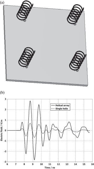
Figure 16. (a) 2 × 2 helical array with inter element distance as mentioned in (6). (b) Simulated transient radiation from a 2 × 2 helical array compared to single element.
Download figure:
Standard image High-resolution image6.3. Shark array antenna
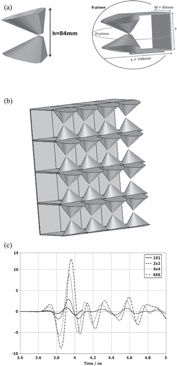
One more innovative development in the transient arrays is the shark antenna array [74]. Conceived with an intention to radiate UWB high power pulses, the array has been carefully designed with a very high transient front to back ratio. The basic element here is a modified biconical antenna with an integrated spark gap between the two cones. The array element is named as 'shark', probably due to its shape it resembles. In order to make the antenna unidirectional, the cones were tilted by an optimal angle of around 12°. To increase the transient front to back ratio (FBR), the back potion of the cones were chopped and a reflecting plate is placed at a distance of 75 mm, shown in Fig17a. The antenna has proved its performance over a decade bandwidth from 0.8 to 8 GHz. With this basic element, a N generators/N antennas array was proposed with an aperture size of 1 ft × 1 ft, containing 16 elements as shown in figure 17(b). The simulated transient FBR is more than 32 dB a very high for a large band antennas. The radiation from array for various combinations compared to that of single element is shown in figure 17(c). This again is a steerable antenna where the steering could be achieved by introducing delays in the feeding points. However, to be specifically mentioned here, that this is only a proposed antenna with simulation results, but its utilization in the high voltage requirements needs to be further investigated.
Figure 17. (a) 3D model of shark antenna. (b) Stacking of shark elements in array. (c) Radiation characteristics of the shark array.
Download figure:
Standard image High-resolution image
7. Conclusion
7.1. Performance comparison
A comprehensive review concerning wide band and ultra-wideband high power antennas was presented in this paper. Geometries and topologies adopted for the design were investigated. Several types and shapes of antennas useful for high power applications were presented. The radiation efficiency and the methods suggested by various researchers to improve the figure of merit (FoM) were presented. The consolidated data of all the antennas discussed in the paper is presented in the table 5. Though none of the developers of the antennas mentioned in table 5 have produced the experimental results of the effects of the radiation on electronic targets. However, as mentioned by Enes in his thesis, the average electric field for coupling to the targets for IEMI would be approximately 9 kV/m. With this consideration, the antennas have the capability to effect the electronics as various distances depending on their FoM and the input provided to them. For example, the half TEM will effect at a distance of only upto 6 m, where as half IRA can effect at 600 m.
Table 5. Comparative chart of the most commonly used WB/UWB antennas for high power applications.
| Antenna | Topology | Dimensions (m) | Input(kV) | Normalized Output @1 m | FoM | References |
|---|---|---|---|---|---|---|
| Half TEM | Single | 2.3 × 0.5 | 113.75 | 52.5 | 0.46 | [28] |
| Combined antenna | Single | 0.43 × 0.4 | 60–70 | 54 | 0.78 | [29, 30] |
| Sub-miniature antenna | Single | 0.28 × 0.28 | 125 | 125 | 1.0 | [31] |
| Helical antenna | Single | 0.19 × 1.33 | 35 | 14 | 0.4 | [35] |
| Biconical antenna | Single | 0.4 × 0.29 | 200 | 60 | 0.3 | [40] |
| Dipole antenna (with corner reflector) | Single | 0.2 | 60 | 28.76 | 0.48 | [41] |
| Dipole antenna (IAS) | Single | 0.4 × 0.25 | 474.2 | 323.2 | 0.68 | [44] |
| IRA | Reflector | 3.66 × 1.21 | ±60 | 1281 | 10.67 | [56] |
| Half IRA | Reflector | 3.08 | 1000 | 5270 | 5.27 | [58] |
| Discone fed reflector | Reflector | 1.6 | 300 | 120 | 0.4 | [59] |
| 0.6 | 200 | 240 | 1.2 | section 5.3-figure 13(c) | ||
| Dipole fed reflector | Reflector | 1.5 | 316 | 1716 | 5.43 | [62] |
| 1.8 | 200 | 800 | 4.0 | section 5.4-figure 14(a) | ||
| Multi element combined array | Array | 1.2 × 1.2 | ±60 | 1670 | 13.9 | [66–68] |
| Helical array | Array | 0.5 × 0.5 × 0.32 | ±225 | 678.8 | 1.5 | [71] |
Starting from the investigation carried out in this review paper, the following general considerations concerning the presented antennas can be highlighted. All the antennas discussed above have been developed for a specific application and hence cannot be compared on individual basis for their performance and hence the drawbacks that these antennas pose are discussed based on their grouping as single element, reflector based and array antennas.
- (1)The single element antennas form the basis for the discussion. Modifications of the general antennas to suit the high power applications make them special in the antenna family. The TEM structures and combined antennas have been specially defined for the purpose but inherently due to their compact feed section, restrict them for use in higher power applications where voltages beyond 100 kV are essential. In such scenarios, the spark gap integrated antennas have shown a path of light to transmit very large voltages by compact structures. One inevitable disadvantage is their omni directional radiation. Though forward bending of the elements or slicing them off to increase the FBR is tried upon, they pose threat to the generator itself.
- (2)However, the development of the single elements does not go into vain if we utilize them in as feeds for the passive reflectors or in arrays. Reflector antennas with these special feeds make the radiation highly directional and the high voltage care needs to be taken only at the feed level. Their large sizes make them unsuitable in compact applications, but in ground-based applications they prove to be the best option.
- (3)Whereas in arrays, the notable advantage is that more number of low power elements can be used with low power generators rather than using a single generator with huge power. The problem that is faced here is the synchronization at the transmitting end, but with laser based synchronous switching, this could also be addressed.
The analysis of the scientific literature shows that a remarkable efforts are made by scientists/researchers worldwide in developing efficient wide band and ultrawide band antennas for high power electromagnetic technology.
7.2. Future of HV UWB antennas
The antennas discussed above have shown their capability to cause IEMI from few meters to few hundreds of meters. These values may not be very promising for these systems to be deployed as directed energy weapons as they demand the weapon carrying platform to go close to the target. This is generally not practical. Rather, the same effect could be achieved by deploying multiple miniature weapons that could be fired from a long distance and reach the target. These miniature weapons need highly compact antennas that could handle high amounts of voltages and currents. Spark gap antennas, to some extent cater for this requirement. Antennas that have solid dielectric material with very high dielectric strength in place of liquids and gases also would be future development towards the miniaturization of the HV antennas.
Competing interests
The authors declare that there is no conflict of interests regarding the publication of this paper.