
Abstract
As display devices based on liquid crystals have matured over the last decades, liquid crystal research has shifted its priorities in slightly different directions, such as sensors, photonics, nanotechnology and even more biologically related fields like drug delivery. This implied a change of emphasis in the development of novel materials, of which a completely new class of liquid crystal based composites emerged, that of nanoparticle-dispersed liquid crystals. The underlying ideas were to add functionality, while maintaining switchability, and the exploitation of liquid crystal self-organisation to build hierarchical nanostructures. Of particular interest for applications are dispersions of carbon nanomaterials, such as fullerenes, nanotubes and the graphene variants, due to their interactions with conventional liquid crystals. While such systems have been investigated for the past two decades, we concentrate in this review on the effects of dimensionality of the dispersed carbon nanoparticles, which goes hand in hand with the more recent developments in this field. Examples are the doping of 0D fullerenes in liquid crystals and implications for Blue Phase stability, or 1D nanotubes in nematic and ferroelectric liquid crystals, questions of dispersibility and applications as alignment media in ITO-free devices. Graphene (2D) and especially graphene oxide are mainly investigated for their formation of lyotropic liquid crystals. We here discuss the more recent aspects of dispersion in thermotropics.
Export citation and abstract BibTeX RIS

Original content from this work may be used under the terms of the Creative Commons Attribution 4.0 licence. Any further distribution of this work must maintain attribution to the author(s) and the title of the work, journal citation and DOI.
1. Introduction
Over the course of the last century, thermotropic liquid crystals have gone from being an interesting curio—the subject of scrutiny by academics in universities—to being one of the most technologically important materials of modern times. The world-wide use of Liquid Crystal Displays (LCDs) has changed the way human beings interact with one another fundamentally. Despite this ubiquity, liquid crystals (LCs) still draw significant attention from scientists the world over. Significant progress has been made in the design of new molecules and the discovery of new phases, as well as novel optical devices and soft materials for robotics applications. A further significant body of study, which this review will dip into, pertains to the doping of thermotropic liquid crystals with solid nano and micro particles. Broadly, there are two main motivations for doing this: (1) to enhance the macroscopic properties of the liquid crystalline host in a synergistic way, or (2) to use the anisotropic properties of liquid crystals to pattern and/or manipulate the particles.
One example of the former are the recently discovered ferromagnetic nematic liquid crystals, where a truly ferromagnetic behaviour was evidenced for a nematic liquid crystal doped with plate like ferromagnetic particles with homeotropic anchoring conditions (see figure 1(a)) [1, 2]. This leads to a coupling between the nematic order parameter and that of the magnetization, M. This coupling provides the basis of true ferronematics, in contrast to most other nematic systems doped with magnetic nanoparticles since the work of Brochard and de Gennes [3]. The latter are termed equivalently, but in fact merely represent ferrofluids with an anisotropic carrier liquid, implying that the magnetization diminishes after an external magnetic field is turned off. True ferronematics and their properties have recently been reviewed by Mertelj and Lisjak [4].

Figure 1. (a) Example for the enhancement of liquid crystal properties by the addition of nanoparticles. Magnetic nanoplates, coated with a homeotropic alignment agent, are dispersed in a nematic liquid crystal. At a volume fraction of Φ = 0.28 a spontaneous ordering transition of the magnetic moments takes place to produce a magnetisation and thus a ferronematic material. Reproduced by permission after [1] under a Creative Commons Attribution 4.0 International License. (b) An example for the exploitation of liquid crystal ordering to assemble microparticles into a 2D photonic crystal. Defects formed at microspheres which are dispersed in a nematic liquid crystal cause an attraction of particles, which can be added at chain ends or laterally(top), producing a stable 2D crystal of microspheres (bottom). Reproduced with permission from [5]. Reprinted with permission from AAAS.
Download figure:
Standard image High-resolution imageAn example for the use of liquid crystals to assemble and manipulate particles, can for example be found in the work of Zumer and Musevic [5]. They create one, two- and three-dimensional [6] colloidal photonic crystals by binding particles together via liquid crystal knotted defects [7] (see figure 1(b)). By combining experiment and theory/computer simulations their groups have largely contributed to the understanding of interactions between colloidal particles in ordered fluids, mediated via defects in the liquid crystal director field. The extensive body of work has been summarised in review articles [8, 9], as well as chapters 4 and 5 of [10].
Investigations of nanomaterial doped liquid crystals often shift with the arrival of novel nanomaterials. In the last two decades the material graphene, comprising of a single layer of sp2 hybridised carbon atoms has been isolated and intensely studied by the condensed matter physics, chemistry, biomedicine and materials science communities. It is noteworthy that all three allotropes of sp2 hybridised carbon (graphene, carbon nanotubes, fullerenes) have all enjoyed periods of intense investigation following each of their discoveries, finding applications in many areas of physical science. Of these, the two anisodiametric materials (carbon nanotubes and graphene) have been shown to form lyotropic liquid crystals when dispersed in suitable (usually isotropic) solvents. Lyotropic liquid crystals are a distinct class of liquid crystals where the constituent parts are typically particles or supramolecular assemblies, rather than individual molecules, which is the case for the class of LCs known as (low molar mass) thermotropics. In these lyotropic systems, the concentration of CNTs or graphene in the system is relatively high, meaning that orientational ordering of the particles spontaneously occurs, as described by Onsager theory. For recent reviews on the topic of lyotropic liquid crystals of this type and recent key research papers in the area, we refer the reader to [11–16]. In this review, we will focus on recent scientific results of doping thermotropic liquid crystals with each of these three nanomaterials. Fullerenes, by contrast, have spherical symmetry and so do not form lyotropic phases when dispersed in any solvent at any concentration. They are also of approximately molecular size. This has led to their incorporation by synthetic organic chemists into other molecules, including those that form the base units of thermotropic LC phases, known as mesogens. Simple mixtures of fullerenes into thermotropic phases have also been studied, but to a lesser extent.
The most important steps in the investigation of dispersions of carbonaceous nanomaterials in liquid crystals are summarised in figure 2, starting with using liquid crystals to align C70 molecules in the early 1990s, through to the observation of fractal aggregates of GO in the mid-2010s.

Figure 2. A timeline showing the most significant developments in the field of liquid crystals with carbonaceous nanomaterials. In 1993, Dolganov, Meletov and Ossipyan report the doping of C70 into a thermotropic smectic phase to study the orientational ordering of the C70 [17]. In 1996, the first mesogens with built-in fullerene units are synthesised (figure reproduced by permission from [18]). In the early 2000s, nanotubes were doped into thermotropic liquid crystals [19–24] (figure reproduced by permission from [22]) and reoriented by electric field application (figure redrawn by permission from [21]). Around the same time, nanotubes were doped into lyotropic liquid crystals for the first time [25, 26] (figure reproduced by permission from [25]), and were themselves used as the building blocks of lyotropic liquid crystals [14, 27] (figure reproduced by permission from [27]}. At the beginning of the following decade, graphene and graphene oxide were shown to form lyotropic liquid crystal phases [11, 28–30] (figure reproduced by permission from [31]). Low concentration dispersions of graphene oxide were later shown to electrooptically switch due to the Kerr effect [32] (figure reproduced by permission from [32]). It was also in this past decade that graphene-based materials were doped into thermotropic LCs for the first time [33, 34] (figure reproduced by permission from [34]).
Download figure:
Standard image High-resolution imageOne of the challenges of this emerging field is achieving good-quality dispersion of nanomaterials in thermotropic liquid crystals. For the carbonaceous nanomaterials discussed in this review, different techniques are often attempted in order to achieve good dispersion, which are listed in (table 1).
Table 1. Techniques used to improve the dispersion of carbonaceous nanomaterials in thermotropic liquid crystals. Example references, which have used these techniques, and a brief assessment of their effectiveness, are also provided.
| Technique | References | Effectiveness |
|---|---|---|
| Using low dopant concentrations | [22, 31, 34–36] | Dependent on the particle in question—fullerenes disperse very well in most thermotropic LCs, carbon nanotubes and graphene oxide flocculate at even very small concentrations (∼ 10−4 wt%). |
| Varying the thermotropic LC used | [36] | Systematically studied for the case of single-walled carbon nanotubes. It was shown that the choice of liquid crystal used can indeed improve the dispersion. |
| Sonication | Nigh-all studies of nanomaterials in liquid crystals employ sonication methods of some kind | Sonication is a common technique to disperse solid particles in liquids. For liquid crystals, the technique generally works less effectively, due to their higher viscosity. Use of high-powered probe sonicators has been employed in the dispersion of nanotubes [36], with limited effect. Sonication can be a useful when employed to first uniformly disperse the particle of choice in an isotropic solvent, into which the liquid crystal is subsequently dissolved. |
| Changing the size of the particles | [34, 37] | C60 fullerenes, being much smaller than the other particles discussed in this review, generally disperse well up to a higher concentration than other particles. Graphene oxide flakes can be easily broken down to smaller sizes by sonication from microns to 100s of nm. However, this does not appear to improve the dispersion in common thermotropic liquid crystals. |
| Surface functionalization of the dopant particles | [38–40] | Of the materials discussed in this review, carbon nanotubes have been functionalized specifically to improve their dispersibility in liquid crystals. Of these attempts, the most effective method is found to be non-covalent functionalization with a co-polymer consisting of pyrene-like and mesogenic units. |
The outline of this review is as follows. In section 2, the use of fullerenes, both as a structural unit in mesogens, and as a dopant, will be described. In section 3, the doping of carbon nanotubes into thermotropic LCs is discussed. Then in section 4, studies of LCs in conjunction with the most recently discovered of our three nanomaterials, graphene, will be outlined. Finally, a brief summary and outlook will be given in section 5.
2. Fullerenes and liquid crystals
2.1. Mixtures of fullerenes and thermotropic liquid crystals
The first doping of fullerenes into thermotropic liquid crystals, to these authors' knowledge, was by Dolganov, Meletov and Ossipyan in 1993 [17]. This study reported polarized absorption spectra which indicated the orientational ordering of the slightly aspherical C70 fullerene. Hereon, we will discuss the use of C60 fullerenes in liquid crystals, which have been studied more frequently in recent years. Being of molecular size and spherical symmetry, studies of LC systems doped with C60 fullerenes have focused typically on the enhancement of the properties of the overall composite, rather than the manipulation of the fullerenes by the anisotropic LC host. One class of technologically important LC properties are the electro-optical ones of ferroelectric LCs. In 2015 Shulka et al [41], reported on the addition of C60 fullerene particles to the ferroelectric SmC* phase. Nanoparticle inclusions are usually dispersed in liquid crystals via a co-solvent—a liquid, in which the nanoparticles are well dispersed and which is also miscible with the liquid crystal under study. Shulka et al follow this method, first dispersing the C60 fullerenes in heptane before adding their chosen ferroelectric LC. The heptane is then evaporated, leaving a dispersion of C60 in the LC. Fullerene concentrations of 0.1 wt% and 0.5 wt% were studied. The electro-optical parameters were investigated by filling the composites in to test cells. It was found that at lower temperatures, the switching time of the LC was significantly reduced by the addition of fullerenes, up to a factor of 2 at 30 °C with 0.5 wt% C60 doping. This offers a faster switching of the transmitted light modulation. The spontaneous polarisation is also slightly reduced by fullerene addition (figure 3). However, the tilt angle and phase transition temperatures remained unchanged. The tilt angle,  is directly related to the switching angle by
  and this determines the electro-optical modulation depth of the ferroelectric LC when switched. Shulka et al use this latter point as evidence for homogenous dispersions of the C60.
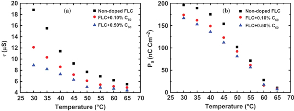
Figure 3. Dependence of the switching time (a) and spontaneous polarization (b) of a ferroelectric SmC* liquid crystalline mixture on temperature and C60 concentration. At lower temperatures, the addition of fullerenes appears to have a marked effect on these parameters, lowering them both. Reproduced from [41] with permission of Taylor and Francis.
Download figure:
Standard image High-resolution imageLow molar mass liquid crystals have been proposed as an alternative to inorganic layers for photo-refractive applications [42]. The photo-refractive effect is a non-linear optical effect where an incident beam of light can modify the refractive index of a material. In crystals, this can occur due to the excitation of electrons from impurity states to the conduction band due to the light itself [43]. In liquid crystals, spatially modulated space charge fields influence the director tilt, and hence the refractive index [42, 44]. Fullerenes can be photo-excited to create charge complexes in solution. This has led to the observation of enhanced photo-refractive effects in LC systems doped with fullerenes. The effect has been observed to be enhanced in fullerene doped liquid crystals in the nematic phase [19, 45, 46] and, recently, blue phases [47].
Fullerene doping has also been shown to be an effective method to thermally stabilize one of the most enigmatic liquid crystal phases—the blue phases (figure 4). In 2020, Draude et al [35] reported that doping of 3 × 10⁻² wt% C60 increase the total temperature width of the blue phases in the compound CE8 from 0.5 °C to ∼4 °C. It is hypothesised that the mechanism behind this is the defect-core-replacement mechanism [48]. In brief, the two of the three blue phase LC phases are constructed of so-called double-twist cylinders (figure 4(a)). When these cylinders meet, there is a local abrupt change in the director field, known as a disclination line (figure 4(b)). The blue phase is a frustrated phase, which simultaneously satisfies the globally isotropic character of the liquid phase and the tendency of the chiral molecules to form helical structures. The disclination lines form a cubic lattice (figure 4(c)) at the cost of free energy due to the elastic nature of the liquid crystal. The diameter of the disclinations, i.e. the region where the director deviates from the double-twist patterns of the cylinders, is estimated to be ∼10 nm. Fullerenes, being smaller than this, can cluster in these disclinations, replacing the LC molecules in this region and hence lowering the total free-energy of the system. This in turn results in a stabilisation of the Blue phase. The same effect was found not to occur for another class of frustrated LC phase—the twist grain boundary (TGB) phases [35]. This was attributed to the much lower rate of diffusion in the lower temperature phases (cholesteric and fluid smectic) between which the TGB phases occur.

Figure 4. (a) The director structure of the double-twist cylinders, which make up blue phases BPI and BPII. (b) The arrangement of double twist cylinders in blue phases I (upper) and II and (lower) and (c) their corresponding disclination line structures. (d) Polarised microscopy image of a BP-N*-SmA* triple point in the compound CE8 with fullerene doping. (e) The phase diagram of CE8 with fullerene doping in the region of the blue phases. (f) Proposed model of blue phase stabilization; the C60 fills the high energy disclination lines, reducing the elastic deformation of the director field and thus lowering the free-energy of the system. Reproduced from [35]—Published by the Royal Society of Chemistry.
Download figure:
Standard image High-resolution imageThe diffusion of fullerenes in liquid crystals, and the thermo-optical properties of the mixture, has been studied by Omena et al [49]. Using a Z-scan technique, the authors measured the far-field light intensity as a function of sample exposure time to extract the thermal diffusivity of their 8 CB LC samples both with and without C60 addition (0.1 wt%). The results indicated that the vanishing critical behaviour of the thermal diffusivity was maintained when C60 was added but was increased by ∼10% in the vicinity of the transition. Omena et al also found that the nematic to smectic A transition temperature was altered by this concentration of fullerenes, decreasing in a linear fashion by up to 2 °C with 0.4 wt% C60 doping.
Thus far, the studies discussed have all either assumed or directly observed that there is no phase-separation of fullerenes and their LC hosts at low concentrations. This fact is supported by the work of Trushkevych et al [50], who show that C60 molecules can be deliberately and irreversibly separated from their LC hosts. To do this, the group started with a cell filled with a chiral nematic phase (N*) liquid crystal doped with well-dispersed C60 fullerenes and then illuminated it with lasers. Both blue (488 nm) and infrared (1064 nm) wavelengths were used. The process of de-mixing the C60 from the N* LC was found to be more efficient with blue light, requiring lower laser power. Using fluorescence confocal microscopy, the team showed that in the regions of laser illumination, the C60 clusters at the cell boundaries, changing the boundary conditions of the N* LC from homeotropic to planar. This in turn causes the formation of chiral structures known as torons, due to the tendency of the N* phase's director field to twist (figure 5). The size of these torons is then controllable by applying an electric field, which means these structures could have interesting electro-optical device applications [50].

Figure 5. (a) Schematic diagram showing the director field of the LC (green lines), an example focus point of the laser beam, and the deposition of C60 at the cell boundaries. (b) confocal microscopy image showing the cross-section of the cell. Points 1 and 3 are where a laser beam was focused at the upper and lower cell boundaries, respectively. The beam was also focused in the middle of the cell layer, between points 2 and 4. The darker parts of the image indicate clusters of phase-separated fullerenes. (d)–(f) The torons caused by laser illumination are subjected to an electric field, U, causing them to shrink in size. When the field is removed, there is a moderate recovery of the toron structure. Reprinted from [50], with the permission of AIP Publishing.
Download figure:
Standard image High-resolution image2.2. Mesogenic units containing fullerenes
The most common use of fullerenes in the context of thermotropic liquid crystals is as a building block in the LC molecules themselves. The first reported synthesis of molecules containing fullerenes which exhibited a thermotropic LC phase was by Chuard and Deschenaux in 1996 [18], who constructed a rod-like molecule featuring a fullerene at its centre. Given the relative bulk of a C60 sphere compared to conventional calamitic mesogens, one of the most basic effects their inclusion causes is in the phase behaviour. The bulky C60 moiety is a hindrance to self-organisation and hence the appearance of mesomorphic phase behaviour [51]. Applications of such molecules could lie in molecular switches. Molecules including ferrocene and fullerene units have been synthesised [52], with charge-separation lifetimes of around half a microsecond. Layers of C60-containing liquid crystals have also been proposed for use in solar cells [51, 53].
A great number of complex and beautiful molecules have been synthesised using fullerenes, including bent-core molecules [54], discotic mesogens [55], and the liquid crystal 'shuttle-cock' [56, 57] (figure 6). However, these fall outside the scope of this review. We refer the interested reader to the chapter 'Fullerene‐Containing Liquid Crystals' by Felder-Flesch, Guillon and Donnio in volume 5 of the Handbook of Liquid Crystals [51].
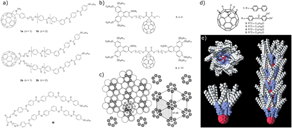
Figure 6. Example chemical structures of C60 fullerene containing bent-core (a) and disk-like (b) mesogenic units, along with that of the liquid crystal shuttle-cock (d). (c) and (d) show diagrams indicating the self-assembly of the disk-lik and shuttle-cock molecules, from X-ray and computer simulations, respectively. Part (a) reproduced from [54] with permission from Wiley, parts (b), (c) from [55] with permission from the Royal Society of Chemisty (permission conveyed through Copyright Clearance Center, Inc.) and parts (d), (e) reprinted by permission from Springer Nature [57] © 2002.
Download figure:
Standard image High-resolution image3. Carbon nanotubes in liquid crystals
3.1. Background
Carbon nanotubes (CNTs) are highly anisodiametric rod-like particles with extreme aspect ratios. They come in two main varieties, single-walled (SWCNTs) and multi-walled (MWCNTs) [58]. The former are hollow cylinders of carbon, whereas the latter consists of a number of such cylinders arranged concentrically. MWCNTs were first observed in the 1950s [59, 60] but were largely ignored for a few decades before an intense revival in the 90s [61]. SWCNTs followed in 1993 [62, 63]. The narrowest SWCNTs are around 7 Å in diameter and typically have lengths in the range of 100s of nanometres up to a few micrometres (aspect ratio 103–104). The record for the longest CNT currently stands at 0.5 m [64]. Like many nanomaterials however, there is typically polydispersity in the size of nanotubes [65]. CNTs can also have different electronic structures, which are related to their chirality. They can be conductors or semi-conductors [66]. However, separating CNTs of a particular band-structure from a given batch has proved challenging [67]. In multi-walled nanotubes, each concentric layer can have different chirality, making predictions of their properties more difficult than the single-walled case [58]. For conductive nanotubes, the conductivity is much larger along the tube axis than in perpendicular directions. In solution, CNTs tend to bundle together due to strong van der Waals forces. This leads to poor dispersibility in water and most common organic solvents. Even apparently good dispersions by visual inspection, can in fact be dispersions of small bundles, rather than separated CNTs, and these two states must be distinguished by other methods [68].
The first combination of CNTs with liquid crystals came in 2001, when Lee and collaborators used nematic liquid crystals doped with trace amounts of multi-walled nanotubes to make novel diffraction gratings [23, 24]. A year later, Lynch and Patrick used common nematic liquid crystals (5CB and E7) to orient carbon nanotubes and then removed the LC, leaving an ordered array of either MWCNTs or SWCNTs [20]. However, the behaviour of the nanotubes within the LC was not discussed, nor the properties of the doped LC studied. Two years later, Dierking et al reported separate mixing of SWCNTs and MWCNTs into E7 [21, 22]. It was observed by scanning electron microscopy, that the nanotubes tended to form bundles. In the LC, these bundles aggregated further, but aligned spontaneously to the far-field director of the nematic phase, as shown by optical microscopy. Furthermore, these bundles could be switched to a more vertical position, slaved to the LC's director through elastic interactions. Consequently, the conductivity of the cell increased rapidly above the threshold voltage as the nanotubes provided more conductive pathways due to percolation of the nanotubes in the LC. The reverse effect has also been demonstrated for nanotube-doped LCs with a negative dielectric anisotropy [68]. These samples were aligned homeotropically and then when an electric field is applied, the conductivity reduced as the director field switched the nanotube network to a planar state [68]. Since this time, there has been a large number of papers regarding the physics, chemistry and engineering of devices like these. This is more literature than can be covered properly in a single contribution, and we refer the interested reader to other excelled reviews on the topic [69–71]. Herein, we give a brief background on how to best disperse nanotubes in liquid crystal hosts, and progress in this area (section 3.2). We then discuss some of the more recent studies of nanotube-doped liquid crystal systems in section 3.3, and further briefly mention the efforts to use CNTs as an alignment medium for LCs in section 3.4.
3.2. Considerations of dispersibility
A significant body of work in the area of nanotube-doped LCs has been in improving the quality of the dispersion. Broadly speaking, the desired constitution of the composite is one where the centres of mass are distributed homogeneously throughout the LC matrix, at all probable length scales. If this is the case, then the macro-properties of the composite become effectively modified by the micro-inclusions. There is of course a critical length-scale for this homogeneity, which is dependent on the application and the experiments used to probe the composite. The majority of studies of liquid crystals use optical microscopy as their main tool, and so a goal of the community since 2004 has been achieving a dispersion of nanotubes in nematic phases that is homogenous as far as optical microscopes can resolve (to the order of ∼0.5 μm). A significant step in this direction came in 2010 from Schymura et al [36], who systematically studied the stability of SWCNTs in the common nematic liquid crystals ROTN, E7, 5CB, 7CB, MBBA, PCH5, PCH7, and 6T7 through sonication and centrifugation. It was found that the highest stable concentrations of SWCNTs were found in E7 and MBBA, at 0.004 wt%. The dispersibility varied largely amongst the tested host LCs. It was also found that the chain length of the LC may be a factor, as PCH7 showed better compatibility with the nanotubes than PCH5. Furthermore, the observation that 6T7 performed poorly casts doubt on whether a high degree of aromaticity is necessary (the 'like dissolves like' principle [72]).
The principle of like dissolves like has also been used in the reverse when it comes to dispersing solid particles in liquid crystals i.e. by decorating the outside of the particles with mesogen-terminated units, such that the bulk LC interacts only with other mesogenic units. The motivations for doing so extend further, however, due to the relationship between surface anchoring and elasticity of LCs. If a solid inclusion is present in a nematic LC matrix, then the director field will be disturbed if the size of the inclusion is larger than the coherence length of the nematic, given by [73]

where  is the surface anchoring energy per unit area and
  is the elastic constant of the LC (in the one constant approximation). To minimise the elastic energy caused by the disturbance to the director field in this case, particle inclusions will tend to aggregate together. Most thermotropic nematic liquid crystals interact strongly with nanotubes via π-π stacking interactions. These interactions can be broken up (i.e.
  can be lowered) by grafting other molecules, either covalently or non-covalently, to the nanotube surface. An example of the former comes from Yoo et al [38], who attached both alkyl chains and mesogenic units to nanotubes functionalized with carboxylic groups (which are now commercially available). They found that both methods improved the dispersion of the MWCNT in both ethanol and a nematic liquid crystal they synthesised. Oxidized nanotubes such as those used in this study are no longer as conductive as their pure carbon counterparts, which limits their device applications [68]. Ji et al instead used a non-covalent approach [39]. They synthesised a novel polymer which had pyrene groups designed to anchor to the nanotubes and mesogenic groups to interact with the LC host. Using this method, Ji et al achieved stable dispersions of nanotubes at 1 wt% in the nematic phase which lasted for over 6 months in their cells [39]. Furthermore, the conductivity as function of applied field of the samples was significantly improved, as the nanotubes were re-orientated by their host's director field. However, such novel polymers are quite difficult to synthesise, and so the majority of recent studies of thermotropic liquid crystals doped with CNTs, which are discussed in the next section, do not use such chemical aids.
3.3. Recent studies of CNT-doped thermotropic LCs
The dielectric permittivity and conductivity are bulk material properties of thermotropic liquid crystals that can be measured easily and quantitatively. These properties can also provide a lot of information about the internal workings of the materials, though correct interpretation is crucial [74]. Recently, Tomylko et al [75] have applied these techniques to the aggregation of MWCNTs in nematic LCs. By measuring the dielectric permittivity,  and conductivity,
  as a function of nanotube concentration, distinct trends in different regimes of concentration can be elucidated (figure 7). In this study, the nematic LC used was the ubiquitous room temperature nematic 5CB and the nanotubes were mixed in the isotropic phase (60 °C) via sonication for 10 min.
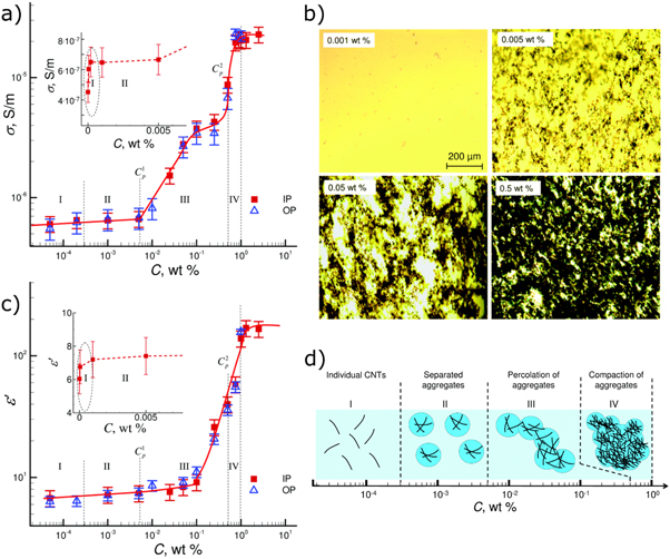
Figure 7. (a) Conductance of an LC cell filled with a nematic LC doped with MWCNTs as function of CNT concentration. Four regions of distinct behaviour are identified. IP and OP stand for measurements using cells with an in-plane or out-of-plane electric field, respectively. (b) Optical microscopy images of the nematic LC samples at different CNT concentrations, taken with the samples between parallel polarizers. The increasingly dark regions are the aggregated nanotubes. (c) Dielectric permittivity of the LC cells as a function of CNT concentrations. (d) Schematic showing a model of CNT aggregation in the four regions identified from the measurements in (a) and (c). Republished with permission of Royal Society of Chemistry, from [75]; permission conveyed through Copyright Clearance Center, Inc.
Download figure:
Standard image High-resolution imageAt very dilute concentrations (10–5–10–4 wt%) the nanotubes are thought to be dispersed well (Region I in figure 7). As the concentration increases to ∼10−3 wt%, the conductivity and permittivity suddenly cease to increase. It is at this doping level that aggregates also become clearer in the microscope, and so it is thought that the CNTs transform from being uniformly dispersed to forming isotropic clusters, separated spatially from one another. Then, at 10−2 wt%, there begins a significant increase in both conductivity and permittivity with concentration, which is a strong indication of the formation of a percolating network of these aggregates of conductive nanotubes between the electrical contacts. At 0.1–1 wt% nanotube loading, the aggregates become compacted and the conductivity and permittivity saturate.
Interestingly, the measurements of Tomylko et al [75] of using in-plane (parallel to the LC director) and out-of-plane electrical fields (perpendicular to the LC director) produced very similar results. This is unexpected since previously it has been shown that individual bundles of nanotubes align with the LC director [21, 22] which, combined with the extreme aspect ratios of CNTs, one would expect would lead to increased anisotropies in the conductivity and permittivity of the composite. The latter has been shown by Singh et al [76] (figure 8). Here, the real component of the dielectric permittivity parallel to the director is shown to increase more than in the perpendicular component. This can be explained by the CNTs being parallel, on average, with the director. Furthermore, Singh et al also report a reduction of the threshold voltage,  required for the Fréedericksz transition of the nematic phase when an electric field is applied to the sample. By applying the equation for the threshold voltage of a normal nematic under strong anchoring conditions,

the authors attribute this reduction to a possible reduction in the effective elastic constant of the composite,  since the moderate measured increase in
  is not sufficient to entirely explain the observed decrease of

Figure 8. (a) Real components of the dielectric permittivity, both parallel and perpendicular to the director, of the nematic liquid crystal W-3017 with increasing MWCNT concentration from 0 wt% (blue), to 0.01 wt% (red), to 0.02 wt% (green). (b) Transmitted light intensity through the test cell as a function of voltage for the same three types of material, showing a decrease in the threshold behaviour for increasing nanotube concentration. Reproduced from [76] with permission of Taylor and Francis.
Download figure:
Standard image High-resolution imageRecently, Ibragimov and Rzayev [77] reported that adding 0.5 wt% of SWCNTs (a large amount compared to other studies mentioned so far) increases  Here, the authors apply the same model as above and instead predict that the effective elastic constant increases—the opposite of what is proposed to happen by Singh et al [76] when nematic phases are doped with CNTs. One possible explanation for this discrepancy could be as follows. Inclusions of large amounts of CNTs cause a compact network of aggregates [75]. SWCNTs have specific surface areas of 1315 m2 g−1 [78]. And so, at these high dopant concentrations there is significantly more surface 'seen' by the LC than in the undoped case, where just the inner cell surfaces provide boundary conditions. This situation is similar to the case in polymer-stabilized liquid crystal devices, where the strong-anchoring assumption of equation (2) (
 where
where  is the anchoring strength) no longer applies, though in this case this is caused by the disruption of the anchoring at the boundaries by nanotube bundles. The critical electric field required becomes [79]

where  is a characteristic length which takes into account the distance between adjacent polymer fibres, or in this case, bundles of nanotubes. This model could explain the observations of threshold increase for large CNT concentrations. Using SWCNTs at lower concentrations (0.01 wt%), Schymura and Scalia found no change in the dielectric anisotropy nor the Fréedericksz threshold compared to their pure E7 LC [80].
As well as using single-walled rather than multi-walled CNTs, Ibragimov and Rzayev also use a different method to disperse the particles in the LC host. In addition to sonication and stirring, the composite, once filled into the cell and cooled to the nematic phase, is subjected to an intense electric field through the application of 40 V to induce turbulence in the liquid crystal. The system is left in this state for two whole days, after which the authors report no aggregates to be observed [77]. Similar effects have also been reported by Tie et al [81] and Dolgov et al [82].
Dispersions of MWCNTs in nematic liquid crystals have also been used recently by Kim et al to produce a simulated biological nerve junction, which can emulate homosynaptic and heterosynaptic functions [83]. For the design of this device, a dispersion of MWCNTs in 5CB was created, and this dispersion was tested in both conventional test cells, and a droplet of it was placed over multiple contacts (figure 9). For this study, the composite material was 0.01 wt% MWCNTs in 5CB, which according to the model of [75], represents a concentration when the percolation of aggregates should start to occur. Indeed, Kim et al find that the conductivity between their contacts increases when the voltage applied is above a certain threshold to orient the nanotubes, meaning electrical pathways are formed between the contacts. Interestingly, the operating temperature of the devices was around 40 °C (the clearing point of 5CB is around 35 °C). Yet, the devices still display this field-effect switching behaviour. The authors attribute this to the formation of pseudonematic domains forming around the nanotubes, due to the strong π–π interactions between the nanotube surface and the 5CB molecules (figure 9(a)). The low-resistance state of the two-terminal device was retained after the electric field was removed for over 24 h, and to actively restore a high-resistance state, the sample was heated to higher temperatures (60 °C–80 °C). It was also found that the number of pulses required to enter the low resistance state was reduced with increased pulse amplitude. In the multi-terminal device (figures 9(c)–(d)), a second, modulating voltage was employed. By increasing the modulation voltage from 5 to 30 V, the switching voltage decreased from 48 V to 27 V. In the second device, the voltages used are higher simply due to the spacing of the contacts. This second device can be used to simulate heterosynaptic functions such as facilitation, potentiation and synaptic weight normalization [83]. This study represents an example application of CNT doped thermotropic LCs, where the clustering of the CNTs is actually the key design element.

Figure 9. (a) Schematic of the pseudonematic domain around the MWCNTs. (b) Two-terminal device schematic and diagram of synapse it simulates. (c) Diagrams of multi-terminal device and synapse it simulates. (d) Optical microscopy image of multi-terminal device. Reprinted (adapted) with permission from [83]. Copyright 2020 American Chemical Society.
Download figure:
Standard image High-resolution imageCarbon nanotubes have also been doped into ferroelectric liquid crystals. In 2014, Yakemseva et al [84] reported studies of MWCNTs dispersed in the commercial LC Felix M4851/050 (Clariant). The effects of adding the nanotubes on the tilt angle, spontaneous polarization, switching time and Goldstone dielectric relaxation mode of the host LC were studied. It was found the tilt angle fell continuously in the concentration range studied, reducing by ∼20% at a doping of 0.04 wt%. The spontaneous polarization increased slightly (∼10%), but the switching time also increased (∼20%). Therefore, Yakemseva et al [84] concluded the main effect of adding the nanotubes on the ferroelectric SmC* phase is to increase the viscosity. However, this is in contrast to an earlier study by Prakash et al [85], who measured a decrease in the switching time of a different ferroelectric LC when multi-walled nanotubes were added. An even larger decrease in switching time was reported by Malik et al [86] in yet further ferroelectric LC material (KCFLC10R, Kingston). Malik et al also reported a larger increase in the spontaneous polarization than Yakemseva et al [84, 86]. It is clear that the studies performed to date on nanotube-doped ferroelectric LCs are not directly comparable, since different LC materials and different sources of nanotubes are used. It has also been shown that nanotube functionalization can play a distinct role in photoluminescence, electro-optics, and dielectric properties of the composite [40].
Nanotubes have also been doped into Blue Phases to see what effect, if any, they have on the stabilization of the frustrated chiral phase [35]. It was found that a small amount of SWCNTs did increase the total temperature range of the Blue Phases in the compound CE8, from 0.5 K to 4 K, at the expense of the cholesteric phase, without completely supressing it. This behaviour is qualitatively similar to that observed in the same study with fullerene doping. However, beyond 10−4 wt% SWCNT doping, there was no change in the phase transition temperatures, and significant nanotube aggregation was observed. It is not clear by what mechanism nanotubes stabilize the blue phase, since while their diameters are approximately that of fullerenes, their lengths are on the scale of microns—significantly larger than the lattice parameters of BPI and BPII, which are only 100s of nm. It is thought that the bundling of single nanotubes to macroscopic bundles of several 10s of nanometres in diameter may reduce their effectiveness in Blue Phase stabilisation, because these length scales, in contrast to the above discussed fullerenes, are larger than the disclination line diameter.
3.4. Carbon nanotubes as alignment media for liquid crystals
Due to their high conductivity and the tendency for strong anchoring of LC molecules to them, carbon nanotubes have been considered as an alternative alignment medium for nematic liquid crystal devices to the likes of indium-tin-oxide (ITO) coated in polymer layers. Recent reports [87], suggest that demand for indium for the display industry will lead to shortages within a few generations. Indium is a component in zinc sulphide mining ores and is extracted during zinc refinement. It is used as transparent electrodes in the form of ITO in the solar cell and liquid crystal display production. Although the shortage of indium is not as pronounced as first thought about ten years ago, several technologies are being developed to either recover the metal from electronic display waste [88, 89], or to replace ITO altogether by a more environmentally friendly, greener technology [90]. For the latter pathway conducting polymers such as PEDOT [91, 92] were developed, or silver nanowire networks [93–95]. But also carbon based solutions are under investigation, for example the use of nanotube films or graphene layers [96]. In principle, if carbon nanotubes can be aligned homogeneously on a surface, then they would fulfil both roles—a conductor for the application of electric fields, and simultaneously an alignment medium. This idea has been realised by Fu et al [97], as demonstrated in figure 10. A schematic of the cell set-up including the aligned nanotube layers is presented in figure 10(a) for a standard twisted nematic cell (TN cell). Figure 10(b) shows the aligned carbon nanotube film at low- and high-resolution scanning electron micrograph in the pictures to the left and right, respectively. A working TN cell is demonstrated in figure 10(c) with the right hand image showing the cell in transmission between crossed polarizers at applied electric fields (on), while the left micrograph shows the pixel in the field-free case (off). The corresponding voltage-transmission curve is depicted in figure 10(d) showing the typical shape, albeit with a somewhat increased threshold voltage and operating voltage when compared to a standard ITO sandwich cell. Other variations of this principle can be found in the embedding of aligned nanotubes in thin polymer films [98], or even with a triple functionality of the nanotubes acting as transparent electrode, alignment layer and polarizer simultaneously [99].

Figure 10. (a) schematic of a twisted nematic cell constructed with transparent carbon nanotube electrodes, which at the same time act as a planar alignment layer. (b) aligned nanotube film at low (left) and high (right) resolution SEM imaging. (c) Transmission-voltage curve as typically observed for TN cells, switching from bright to dark for increasing voltage above the threshold voltage Uth. Reprinted from [97] with permission from Elsevier.
Download figure:
Standard image High-resolution imageHomeotropic (vertical) alignment has also recently been achieved using carbon nanotubes [100]. This was achieved by growing nanotubes vertically using plasma enhanced chemical vapor deposition catalysed by nickel nanoparticles deposited on the surface of chromium coated glass. Using two of such substrates and a nematic liquid crystal with a negative dielectric anisotropy (in this case BYVA-01), the authors were able to construct a simple switching device which was dark between crossed polarizers in the off state (homeotropic alignment). This device performed comparably well to a commercially available cell with homeotropic alignment (figure 11). Furthermore, a slight tilt of the CNTs leads to homogeneous planar alignment in the on state through the avoidance of reverse tilt domains.
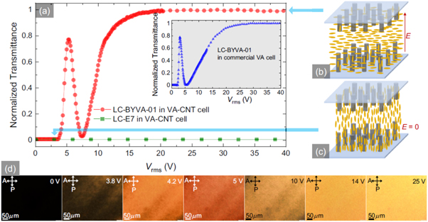
Figure 11. (a) Normalized light intensity transmitted through the nanotube vertical alignment device. The blue arrows show the dark and bright states. The director field orientation with respect to the nanotubes is shown for both of these cases in (c) and (b) respectively. The inset shows the same curve for a commercial cell with homeotropic alignment, using the same LC. (d) Polarized optical microscopy images showing the increasing intensity of transmitted light with increasing voltage. Reprinted figure with permission from [100]. Copyright 2020 by the American Physical Society.
Download figure:
Standard image High-resolution image4. Graphene-doped thermotropic liquid crystals
4.1. Graphene-based materials
Graphene is the third and final in the triumvirate of carbon dopants discussed in this review, and also the most recent allotrope of carbon that is stable at room temperature to be isolated. The first studies of graphene, or at least few layer thin graphite films, can be traced back to Boehm et al [40] in 1962. However, by way of analogy to the case of Iijuma and CNTs, the present surge in graphene related research originated with Geim, Novoselov and collaborators and their 2004 work [101], where they isolated graphene films via mechanical exfoliation of graphite—the common three-dimensional layered crystal of carbon. The numerous properties of graphene such as high mechanical strength [102], high transparency [103], high electron mobility [104] and flexibility make it an attractive candidate material for new technologies. However, in order to make products from graphene, there is a need for a production method that is scalable. This need has led to the exfoliation of graphite oxide, a material which traces its origins back to the 19th century, and the production of graphene oxide. Graphene oxide is a very different material to graphene. Whilst in isolation, graphene is a semi-metal. Graphene oxide, however, is an insulator. The strong oxidizers used to create graphite oxide cause the introduction of various polar oxygen functionalities such as epoxy, hydroxyl, carbonyl and carboxylic acid groups, all of which disrupt the sp2 hybridized bonding network and hence the graphene oxide sheets become insulating. However, the polar groups make for the facile intercalation of polar solvents, such as water, to efficiently separate the monolayers. Once in this state, the graphene oxide can be reduced, by either chemical or thermal means, to restore some of the conductivity [105].
4.2. Dispersions of graphene materials in nematic and ferroelectric LCs
Similarly to carbon nanotubes, graphene, having an extreme aspect ratio, offers an attractive avenue to modify bulk properties of nematic liquid crystals such as the dielectric anisotropy, viscosity and switching thresholds. The last decade has seen many studies on graphene-base material doped into nematic liquid crystals. In 2012, Gökçen et al studied a composite of the LC mixture E7 and 0.05 wt% graphene [33]. They discovered that the Fréedericksz threshold voltage for switching was increased dramatically, from 0.1 V with no graphene, to 1.2 V with 0.05 wt% graphene. Gökçen et al did not report any changes in the phase transition temperatures of the host liquid crystal by graphene addition. However, in 2013 Wu and Lee reported that graphene nanoplatelets, added to the liquid crystal 8OCB, caused the clearing point to increase as a function of dopant concentration [106] (figure 12).
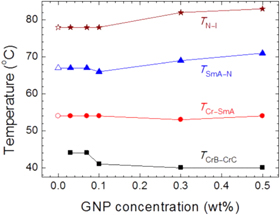
Figure 12. The phase diagram of the liquid crystal compound 8OCB as a function of graphene nano platelet concentration. Note the slight increase in the clearing point and the nematic-smectic transition. Reprinted from [106], with the permission of AIP Publishing.
Download figure:
Standard image High-resolution imageIn 2015 , Basu et al [107] reported a study of the liquid crystal MLC-15600-100 with dispersed graphene particles. In contrast to Wu and Lee, it was found that the addition of these graphene particles lowered the clearing point of the LC (figure 13(a)). Furthermore, Basu et al report a dramatic increase in the dielectric anisotropy of the LC when the concentration of graphene particles is increased. However, after a concentration of 2.29 wt% this value begins to decrease. This turning point in the behaviour is correlated with the appearance of small aggregates in the sample at higher concentrations. The authors propose that strong π–π stacking interactions between the LC molecules, combined with the honeycomb structure of the graphene particles, drives orientation of the LC molecules at the graphene surface. This ordering then remains above the clearing temperature, leading to pseudo-nematic domains. Experimental evidence for these domains is reported in the form of electric field dependent permittivity above the clearing point, which can be interpreted as due to the rotation of the graphene particles, which is slaved to the rotation of the pseudo-nematic domains (figure 13(e)).
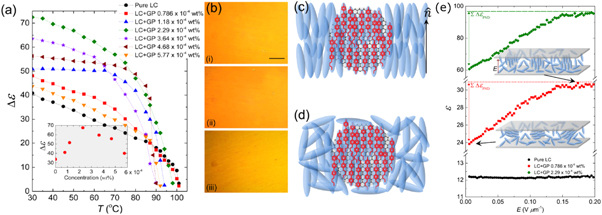
Figure 13. (a) Temperature dependence of the dielectric anisotropy of the nematic liquid crystal MLC-15600-100 for different concentrations of graphene doping. (b) Microscopy images of (i) the pure LC, (ii) the LC with 2.29 × 10⁻⁴ wt% and (iii) 5.77 ×10⁻⁴ wt% graphene particles. The scale bar represents 200 μm. (c), (d) Schematic showing the proposed orientation of LC molecules on the sheets in the nematic phase and isotropic phase, respectively. (e) Variation of dielectric permittivity with electric field. The increase is proposed to be caused by the rotation of graphene flakes and the pseudo-nematic domains on their surfaces, as shown in the inset cartoons. Reprinted from [107], with the permission of AIP Publishing.
Download figure:
Standard image High-resolution imageThe graphene used by Basu et al was a commercial material supplied dispersed in ethanol, with a claimed carbon content of 99.99% (Graphene Supermarket, USA). Graphene oxide particles have also been studied as dopants for nematic liquid crystal systems. Al-Zangana et al studied dispersions of graphene oxide (GO) in 5CB both using dielectric spectroscopy [37] and electro-optical [34] studies. In their dielectric studies, Al-Zangana et al doped 5CB with GO concentrations of 0.4, 0.6, 0.8, 1, 2 and 3 wt%. Optical microscopy confirmed that there was a strong aggregation of the GO particles in the LC (figures 14(a)–(b)). Also, the samples displayed a dielectric relaxation in the region of 104–105 Hz, which pure 5CB does not show (figure 14(c)). One explanation for this relaxation could be dramatically slowed down rotational modes of the 5CB molecules near the GO surface because of strong anchoring [37]. Also, the dielectric constant of these composites was found to be much higher than for un-doped 5CB, which is attributed to the graphene oxide component [37, 108]. In their electro-optical studies [34], Al-Zangana et al found that the switching on time above the Fréedericksz threshold was unaffected by GO concentration, whereas the off time decreased by a factor of ∼7 with 0.4 wt% GO doping. Furthermore, the threshold voltage for switching was found to increase with GO content, similar to what was found by Gökçen et al for the case of doping with graphene [33]. Again, GO was observed in the microscope to aggregate in 5CB at every concentration studied (down to 0.02 wt%).
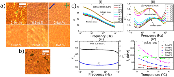
Figure 14. Polarized microscopy images of 5CB doped with different concentrations of GO. At low concentrations, GO-free regions can be seen (circled). The blue arrow indicates the rubbing direction, and the green arrows the polarizer orientations. (b) POM image of 5CB with 0.04 wt% GO content with the rubbing direction parallel to one of the polarizers, indicating the highly distorted director field around the GO aggregates. (c) real (i) and imaginary (ii) parts of the dielectric permittivity as functions of frequency and temperature for 5CB with 0.8 wt% GO doping. Pure 5CB shows no relaxation behaviour (iii). Increasing the concentration of GO increases the relaxation frequency of the composite (iv). Reproduced from [37] under the terms of a Creative Commons Attribution 4.0 International License.
Download figure:
Standard image High-resolution imageAl-Zangana et al did not observe significant modification of the transition temperatures of the host liquid crystal with the addition of GO [34]. However, Javadian et al in 2017 [109] reported significant changes to the clearing point of a similar cyanobiphenyl liquid crystal due to GO doping. The largest change was an approximate 12 °C increase to the clearing point temperature at a loading of 0.75 wt% GO. In a study of GO-doped 6CB Özgan et al found that GO loading lowers the clearing point by up to approximately 2 °C at 2 wt% GO loading [110]. However, unlike Al-Zangana et al [34], Özgan et al [110] observe the Fréedericksz threshold voltage to first decrease with 0.25 wt% GO, then increase again above the value for the pure LC as more GO is added.
Indeed, it appears that there is significant discrepancy in the literature when it comes to the effects on the thermal and electro-optical properties of nematic LCs by addition of graphene or graphene oxide. For example, in a study of 2018, Dalir et al [111] find that the Fréedericksz threshold voltage increases with GO doping, in agreement with the findings of Al-Zangana et al [34]. However, Mrukiewicz et al [112] found that addition of GO particles significantly decreases the threshold (by a factor of 2 at 0.3 wt% doping). Then, Yadav et al [113] also reported in 2019 a continuous decrease in the threshold for the concentration range tested (0.04–0.3 wt%). In 2019, Cirtoaje et al [114] reported that the addition of graphene quantum dots to 5CB lowered the threshold voltage by approximately a third at low temperatures, though the behaviour was somewhat more erratic at higher temperatures. Graphene quantum dots are commercially available and structurally are somewhat similar to reduced graphene oxide but they are instead fabricated by acid treatment of coal, and are ∼10 nm in size—significantly smaller than the GO particles used in other studies (approximately in the range 100 nm-10 μm).
In 2014, Kumar et al [115] showed that doping graphene quantum dots (QDs) into the commercial ferroelectric liquid crystal ZLI 3654 (Merk) significantly improves the photo-luminescence intensity (factor of 3 increase) and the switching time (reduced by  34%) of the LC. These QDs were home-made, from a graphene oxide precursor, and had diameters of around 5 nm. Also in 2014, Basu [116] reported that the addition of some commercially available graphene particles significantly improved the switching properties of a ferroelectric LC mixture MX40636 (Vision). A composite of 0.04 wt% was studied, and it was found that the switching time was decreased, the spontaneous polarization was increased, and the viscosity was decreased (figure 15). The switching time,
  can be related to the spontaneous polarization,
  and the rotational viscosity,
  via [117]

where  is the applied electric field. Basu hypothesises [116] that the increase in
  is due to the ordered anchoring of the LC molecules on the graphene surfaces, increasing the order parameter due to π–π stacking interaction and hence increasing
  Furthermore,
  is thought to be reduced in the composite by the reduced number of free ions in the system, leading to less friction.

Figure 15. Enhanced properties of a ferroelectric LC with 0.04 wt% graphene. Reduction in switching time (a), increase in spontaneous polarization (b) and reduction in rotational viscosity (c). The Inset in part (b) shows the transient response in transmitted intensity through the sample between crossed polarizers as a triangular wave AC electric field is applied. From this, it can be seen that the  peak is larger and ion bump is smaller in the case of the graphene-doped sample. Reprinted from [116], with the permission of AIP Publishing.
Download figure:
Standard image High-resolution imageMalik et al [118] found that doping graphene oxide into a different room temperature ferroelectric LC (BDH 764E), to a concentration of 0.1–0.2 wt%, made little effect on  and increased the rotational viscosity (figure 16). This is in stark contrast to the findings of Basu [116]. However, it is important to point out that Malik et al used (home-made) graphene oxide, whereas Basu used commercially obtained graphene particles. Malik et al suggest that the measured increase in the viscosity, which is derived by measuring the switching time, could be due to collection of GO at the ITO cell boundaries affecting the alignment of the LC. Using partially reduced graphene oxide at 0.5 wt%, Lapanik et al [119] observed an increased spontaneous polarization, tilt angle and a reduced response time. The concentration ranges, type of dopant material and host LC used in these studies all differ, nevertheless, it is clear there is much more work to be done in the area of doping ferroelectric LCs with graphene-based materials, in order to elucidate what factors affect the observed behaviour.

Figure 16. (a) The rotational viscosity (here labelled as ) and spontaneous polarization (b) of both pure and GO-doped ferroelectric liquid crystals as measured by Malik et al [118]. Reprinted with the permission of AIP Publishing.
Download figure:
Standard image High-resolution imageAs well as doping the Blue Phases with C60 fullerenes and SWCNTs, Draude et al also added small amounts of graphene oxide to these frustrated phases. Graphene oxide performed similarly but slightly better to stabilize the Blue Phases than the other two nanomaterials, extending the total Blue Phase range of CE8 by approximately 4.3 K using 10−3wt% doping. The graphene oxide used was synthesised by a modified Hummers method, and had a broad distribution of flake sizes (figure 17(a)), with an average size of 4.4 μm. This size is much larger than the lattice parameter of BPI and BPII, and far bigger than the diameter of lattice disclinations ( 10 nm), meaning defect-core replacement cannot be the mechanism of stabilization in this case. Instead, the authors propose that the graphene oxide sheets may stabilize grain boundaries (figure 17(b)). The favourable π–π stacking interactions of the CE8 molecules and the graphene at grain boundaries may lead to a reduction in the free energy penalty induced by such boundaries. This idea is somewhat supported by reports of graphene oxide collecting at other boundaries, such as the interface between immiscible liquids [120, 121].
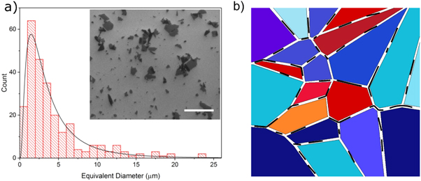
Figure 17. (a) the graphene oxide size distribution used by Draude et al in the doping of LC Blue Phases (b) a model of Blue Phase stabilization by graphene oxide collecting at grain boundaries. Reproduced from [35] - Published by The Royal Society of Chemistry.
Download figure:
Standard image High-resolution image4.3. Graphene as an alignment layer for liquid crystals
In section 3.4 we have shown that thin nanotube layers can be used as transparent electrode for electric field application to liquid crystal display devices. Similarly, it is naturally obvious that also graphene was proposed as a material for transparent electrodes, replacing ITO in liquid crystal devices. This was first demonstrated by Blake et al [122] as shown in figure 18 on a cell consisting of a bottom graphene electrode with planar polymer alignment layer and a top ITO electrode with alignment layer. As the voltage progressively increases, the transmission of the cell through crossed polarizers decreases, due to a vanishing of the birefringence when reorienting the nematic molecules from a planar position at zero volt to a homeotropic position at applied voltage (figure 18(a)). The corresponding transmission-voltage curve is depicted in figure 18(b) with the blue line for monochromatic light at a wavelength of 505 nm, and the red line for white light.
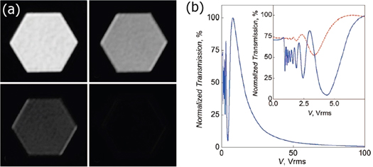
Figure 18. (a) A hybrid graphene-ITO liquid crystal device illustrating the nematic director reorientation from planar to homeotropic through the vanishing transmission for increasing voltage. (b) Corresponding transmission-voltage curve for green light at wavelength 505 nm (blue) and white light (red). Reprinted with permission from [122]. Copyright 2008 American Chemical Society.
Download figure:
Standard image High-resolution imageIt was later demonstrated by Kim et al [123] that the polycrystalline domains of graphene layers can be imaged using liquid crystals. Briefly, a thin layer of calamitic liquid crystal is coated onto a sheet of graphene, which is placed between crossed polarizers. Due to π–π stacking forces between the graphene and the molecules, the LC director changes direction in adjacent crystal domains, thus influencing the intensity of the image observed [123, 124]. This effect as led to graphene being used as an alignment layer and an electrode. Such devices with all-graphene electrodes have been demonstrated, for example by Basu and Shalov [125]. Numerous studies for the use of graphene-based materials have been carried out, employing not only graphene itself, but also graphene oxide, GO, reduced graphene oxide, rGO, or hybrid materials like graphene wrapped silver nanowires. A lot of these studies have been summarized in [126] and [127].
The main problem in using graphene as transparent electrode material to replace ITO lies in the compromise between sheet resistance and transmittance. Industry requirements are of the order of 10 Ω/□ for the sheet resistance and >90% for the transmittance. A single layer graphene film fulfils the transmission condition but falls well short for the sheet resistance. Increasing the graphene film thickness reduces the sheet resistance, but at the same time also the transmittance is largely reduced. An analysis shows that currently graphene is certainly still a candidate for transparent display device electrodes, but that other mechanisms like doping need to be introduced to just barely fulfil the industry standards [128].
5. Summary and outlook
We have shown that by the addition of carbon-based colloidal particles to liquid crystals a wealth of novel materials are created, which enable a whole range of interesting and fascinating applications in many fields outside of the traditional display devices. Low-dimensional carbon nanoparticles, such as 0D fullerenes, 1D nanotubes or the 2D structures of graphene and graphene oxide play a central role in the development of new, self-organised fluid systems, dispersions and composites. These materials find use in the stabilization of frustrated phases like Blue Phases, to be exploited for novel displays, photonic structures and liquid crystal based lasers. But also, for the development of sensors, the construction of ITO-free transparent electrodes and in the tuning of material properties for THz devices. Further applications can be envisioned in biologically relevant systems, such as artificial nerves, or for medical use in drug delivery and controlled drug release.
We have here reviewed the latest developments in the liquid crystal field particularly emphasising the fullerenes, nanotubes and graphene allotropes of carbon as dispersants in thermotropic systems as examples of low-dimensional additives. Other carbon materials have also been studied and it is anticipated that these will gain further interest in the future. For example carbon fillers such as carbon black were investigated in composites with liquid crystal polymer (LCP) resins with respect to their improved electrical and thermal conductivity [129, 130], their rheological properties [131, 132], or mechanical properties [133]. Such LCP-carbon black composites have recently been used to demonstrate a methanol vapour sensor [134].
Liquid crystal elastomers (LCE) are an established aspect of liquid crystal as well as polymer research, and it has been shown that the addition of carbon nanoparticles/carbon black increases the actuation sensitivity [135] and can be exploited to produce LCEs with an on demand insulating to conducting transition [136] via a gel-swelling technique. In the future it can be expected that such systems will be revisited in the light of developments in the fields of artificial muscles and robotics. An illustrative example of a liquid crystal elastomer electric locomotive has just been published by Meng Wang and co-workers [137], which is shown in figure 19.

Figure 19. (a) A liquid crystal elastomer film in combination with a layer of carbon black bends on application of an electric voltage. (b) For a cylinder arrangement on a conductive track, this causes a deformation of the cylinder, leading to stepwise translational motion. (c) Practical demonstration of the liquid crystal elastomer electric locomotive. Reprinted with permission from [137]. Copyright 2020 American Chemical Society.
Download figure:
Standard image High-resolution imageThe device is based on a layered material of a liquid crystal elastomer on a carbon black layer. Application of a voltage results in a bending of the composite structure with a response time of approximately 30s (figure 19(a)). A cylinder of such a material on a conducting track thus deforms reversibly, leading to a stepwise motion as illustrated in figure 19(b). A real-life demonstration is shown in part (c) of the figure. In addition, carbon black absorbs UV radiation and can thus enhance the UV stability of liquid crystal based devices and protect LC polymers from radiation degradation.
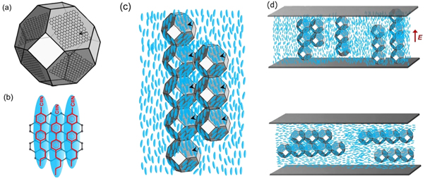
Another carbon material that will certainly catch the attention as a dispersant in liquid crystals in the future is nanodiamond. Nanodiamond is of interest not only through its mechanical performance, but especially also due to its chemical resistance, bio compatibility and non-toxicity, which makes it attractive for medical use. Furthermore, it is ideal for targeted functionalization by surface chemistry and can be modified as a fluorescent probe. The properties of liquid crystals doped with nanodiamond are dependent on their size and surface chemistry [138], and evidence has been presented via dielectric measurements that nanodiamonds self-assemble into chains in a liquid crystal host (figure 20), which are reoriented by applied electric fields, following the director reorientation [139]. This impacts on the properties of the liquid crystal, leading for example to a faster electro-optic response.
Figure 20. (a) The faces of a nanodiamond interact with the biphenyl rings of 5CB via sp3 hybridization (b). (c) In a bulk liquid crystal sample, the nanodiamonds self-assemble in chain-like structures, which can be reoriented when an electric field is applied to the liquid crystal, exceeding the Freedericksz threshold (d). [Reproduced by permission after [139], under the terms of a Creative Commons Attribution (CC BY) license.
Download figure:
Standard image High-resolution image
At last, it is conceivable that meso-graphite will also find its way into liquid crystal based materials and applications. Graphite micro-powders have been used as lubricants for a long time, and so have (discotic) liquid crystals [140]. It is thus easily conceivable that a mixture of graphite powder and liquid crystal may produce materials with enhanced tribology and lubrication properties. Graphite nanoparticles have further been used as electro-thermal layer materials in combination with inverse opalite LCEs to produce tuneable structural colours for photonics [141]. Judging from the wealth of possible materials and proposed applications, research on liquid crystal—carbon allotrope dispersions will continue to flourish in the years to come.
Acknowledgments
A P D would like to thank the EPSRC for funding through the Graphene NOWNANO Centre for Doctoral Training, grant number: EP/L01548X/1.
Data availability statement
No new data were created or analysed in this study.