


Abstract
For a neodymium glass laser, which is used to pump the parametric amplifier of the PEARL facility, we investigate the problem of filling the pinholes of vacuum spatial filters with plasma resulting from the ablation of the pinhole surface by laser radiation. The time of plasma expansion is measured and the causes of its appearance are determined, among which the main ones are the spherical aberrations of the lenses of spatial filters, which increase the intensity at the pinhole edges. With the total spherical aberration of the spatial filters, which lowers the Strehl number to 0.15, two nanosecond pulses with energies of 130 – 140 J, delayed relative to each other by 1.8 ns and freely passing through the final spatial filter, are generated on the PEARL facility.
Export citation and abstract BibTeX RIS
1. Introduction
Neodymium glass lasers with pico- and nanosecond pulse energies of hundreds of joules and above are employed in high-energy physics and laser fusion [1, 2], for laboratory modelling of astrophysical phenomena [3, 4], as well as for obtaining superstrong fields – laser pulses of petawatt power. In the latter case, neodymium glass lasers are used to directly amplify chirped femtosecond pulses [5] as well as (upon conversion to the second harmonic) to pump titanium-sapphire crystals [6 – 10] or parametric crystals [11 – 14]. A feature of parametric amplification is the short duration of the pump pulse: it should be of the order of 1 ns, i. e. the same as the chirped pulse duration.
Technological difficulties in making the rods of neodymium-glass laser amplifiers limit their maximum diameter to about 10 cm. This is the diameter of the output amplifiers of the pump laser of the PEARL facility [12]. The energy of nanosecond pulses at this pinhole cannot exceed 250 – 300 J due to small-scale self-focusing, which leads to breakdown. At the same time, the energy stored in the active elements is much higher. To safely extract this energy in one shot, we introduced and implemented [15] the idea of amplifying two sequentially propagating pulses spaced in time, which is equivalent to pulse lengthening. These pulses traverse the same elements of the pump laser and can efficiently extract the energy stored in the amplifiers. Furthermore, as shown in Ref. [16], in the course of amplification the temporal distortions of each of the pulses are several times smaller than for one pulse amplified to the same total energy. This facilitates the production of quasi-rectangular pulses at the output of laser amplifiers and enables a higher-efficiency conversion of this pulsed radiation to the second harmonic.
In Ref. [15], the energies of two pulses of 300 and 200 J were achieved for a 7-ns delay between the pulses. This result was obtained for the 'old' version of the laser, which made use of vacuum spatial filters with long-focal-length and therefore low-aberration lenses. The spatial filter (a Keplerian telescope with a pinhole at the focal waist) transfers the image from one laser amplifier to the next one, matches the diameters of the laser beam in the amplifiers and cuts off high spatial harmonics. The length of the spatial filters was ∼9 m. Since the image transfer was affected between the amplifiers, one amplifier stage, as well as the spatial filter, had a length of 9 m. To optimise the work space, we shortened the spatial filter lengths to 4 m. The laser became twice as compact, but the telescope lenses turned out to be significantly more aberrational. In this case, the total spherical aberration of all telescopes did not lower the efficiency of frequency doubling in a KDP crystal. However, the execution of experiments with the amplification of two consecutive pulses for the compact version of the laser revealed the following problem: the second pulse ceased passing through the spatial filters. The present paper is concerned with the investigation and solution of this problem – the filter 'locking'.
2. Problem of spatial filter locking
The experimental setup is depicted in Fig. 1. A 1-ns long pulse of an Nd : YLF master oscillator with a wavelength of 1054 nm and an energy of 3 mJ was divided into two replicas of orthogonal polarisation, both their energy ratio and the time delay being adjusted. After that, the pulses were delivered to a multistage neodymium glass amplifier consisting of rod amplifiers with diameters from 10 to 100 mm. Accommodated between the amplifiers were vacuum spatial filters and Faraday isolators designed to work with arbitrary radiation polarisation. Figure 1 shows only the last two amplifiers and one filter, a detailed description of the configuration can be found in Ref. [15]. At the laser output, a polariser divided the amplified pulses into two channels. Upon frequency doubling in KDP crystals, these pulses are employed to pump parametric amplifiers. The output diagnostics included the measurement of near- and far-field energy density distributions using CCD cameras, the measurement of pulse waveforms using a fast photodetector, and the measurement of their total energy with a pyrodetector. When measuring the near-field energy density distributions, the beams corresponding to each pulse were separated by a polariser (a birefringent wedge made of Icelandic spar) and both arrived at the same CCD camera.
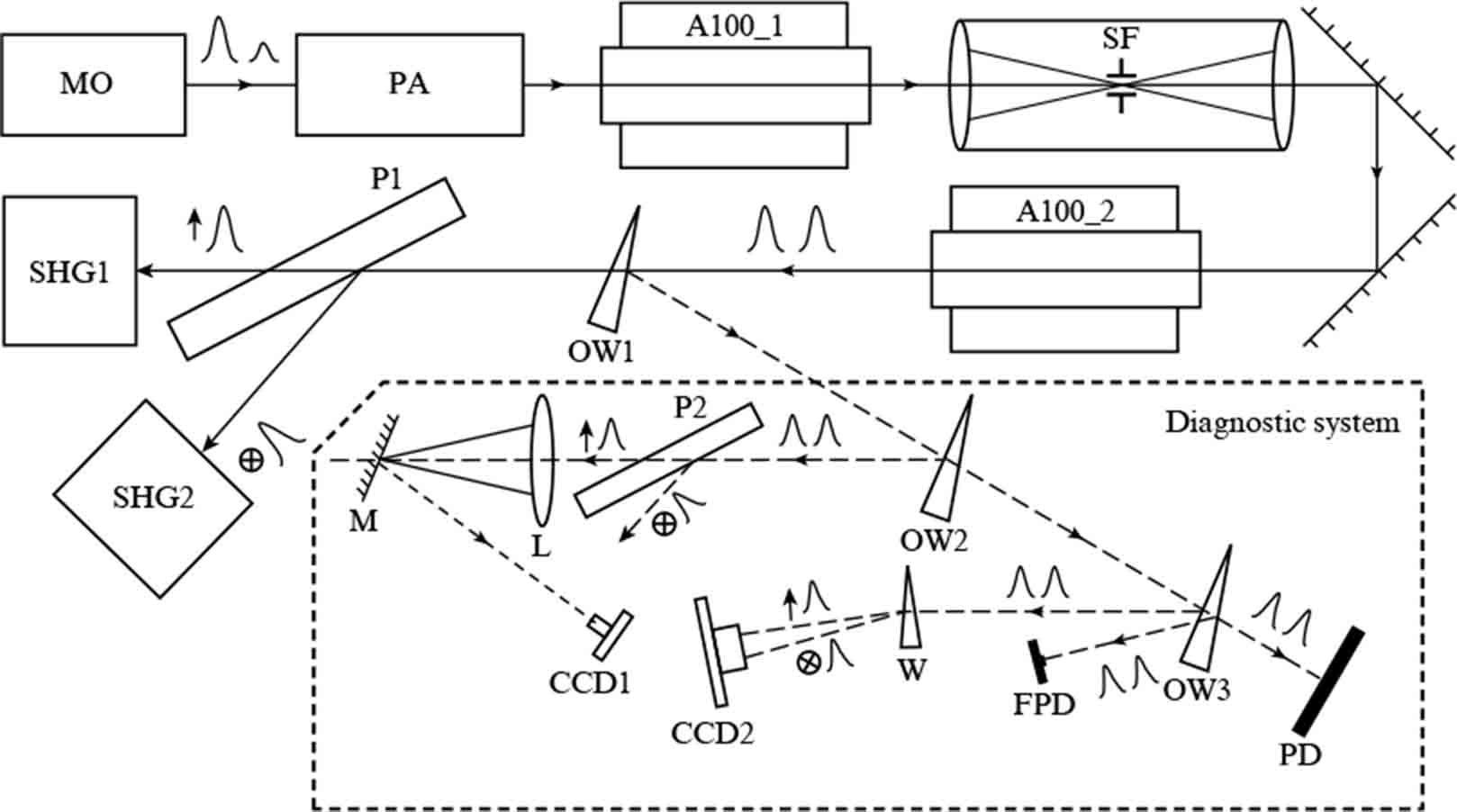
Figure 1. Configuration of the pump laser of the PEARL facility: (MO) master oscillator; (A100) neodymium glass rod amplifiers 100 mm in diameter; (SF) vacuum spatial filter; (P) polarisers; (W) wedge of Icelandic spar; (OW) optical wedges; (SHG) second harmonic generator; (PD) pyrodetector (energy meter); (FPD) fast photodetector (pulse waveform meter); (CCD) digital cameras [far-field (CCD1) and near-field (CCD2) meters of radiation energy density distribution]; (L) diagnostic lens; (M) mirror with a hole; (PA) neodymium glass preamplifiers of smaller diameter and spatial filters between them.
Download figure:
Standard imageThe plasma production in the focal waist is the cause of spatial filter locking, because the laser radiation is scattered in the nonuniform plasma. To prevent this, the pinhole is made of a material consisting of as heavy atoms as possible. In our experiments use was made of tantalum. In order for the spatial filter to perform its function of cleaning the laser beam from small-scale nonuniformities, the pinhole radius is usually chosen equal to 10 – 20 diffraction-limited beam radii [17, 18]. Proceeding from this, the radius Rd of the pinhole of the spatial filter SF (Fig. 1), whose lenses had a focal length of 2 m, was taken to be 0.45 mm, which was approximately 15 diffraction-limited beam radii. As shown by experiments, a nanosecond pulse with an energy of 250 J passes freely through this filter, i. e. no radiation scattering in the plasma is observed. The plasma nevertheless appears in this region, which was discovered during experiments with two pulses.
With an interpulse delay of 7 ns (as in Ref. [15]), the second pulse did not pass through the filter when the energy of the first pulse reached the value of 6.7 J. Shortening the time delay to 1.8 ns made it possible to observe the onset of spatial filter locking at an energy of the first pulse of about 120 J. This will be discussed in more detail in Section 4 of our paper. Therefore, the plasma appears even for a relatively low energy of the first pulse. What matters is the time of filling the pinhole with the plasma. The higher the energy of the first pulse, the hotter is the plasma formed at the edge of the pinhole, the faster it fills the hole and the less time it takes to lock the spatial filter.
We estimate the time of ablation plasma expansion from the edge of the pinhole. As is well known, the velocity of adiabatic gas expansion in vacuum is defined by the expression [19, 20]
where Cs is the sound velocity (for plasmas, the ion-sound velocity) and γ is the adiabatic exponent. For a monatomic ideal gas, γ = 5/3; therefore, U = 3Cs is a well-known formula for estimating the velocity of plasma expansion into vacuum. The ion-sound velocity
where kB is the Boltzmann constant; Te is the temperature of the electron component; Z is the average ion charge state; and mi is the ion mass. The electron temperature may be estimated from the energy balance equation for the stationary expansion of a near-critical density plasma in vacuum, which was derived, for instance, in Ref. [21]:
where Id is the laser intensity at the edge of the pinhole; nc is the critical plasma density; and coefficient 0.8 defines the absorbed fraction of laser energy, we assumed its typical average value (see, for instance, Ref. [22]).
We compare the above formulas to obtain the expansion velocity in vacuum for the plasma produced in the tantalum pinhole in the ablation by the radiation with a wavelength of 1054 nm:
where α = 6.6 × 102 cm s−1 W−1/3. To estimate, we assume that tantalum is completely ionised and Z = 73. Then, at an intensity at the pinhole of the order of 5 × 10¹¹ W cm−2 (which corresponds to a pulse energy of 120 J, see Section 3), the velocity U ≈ 2.2 × 107 cm s−1 and the plasma will fill the pinhole with a radius of 0.45 mm in about 2 ns. If the intensity at the pinhole is of the order of 3 × 10¹⁰ W cm−2 (which corresponds to a pulse energy of 6.7 J), then U × 8.6 × 106 cm s−1 and the plasma will fill the pinhole with a radius of 0.45 mm in about 5 ns. These estimates agree nicely with the values obtained experimentally.
The simplest way to eliminate the filter locking is to increase the pinhole diameter. However, its function of spatial filtering of the laser beam becomes worse in this case. In order to determine how much the radius of the pinhole can be increased and what the conditions for the ablative plasma formation on its surface are, we studied in detail the distribution of laser radiation intensity in the plane of the pinhole of the spatial filter SF. We selected precisely this filter, because it is most loaded from the standpoint of radiation energy density in the focal waist, while in the preceding filters the energy density is lower and the spherical aberrations are smaller.
3. Measurement of intensity distribution at the focus of the spatial filter
The radiation from the output of the A100_2 amplifier was reflected by two glass wedges and directed to a diagnostic lens with a focal length of 2.64 m (Fig. 1). In the focal plane, optically conjugate to the focal plane of the spatial filter SF, there was a mirror with a hole of radius 0.78 mm. The paraxial part of the laser beam passed through the hole, and the radiation reflected from the mirror arrived at a 16-bit CCD camera. The planes of the mirror and the CCD camera matrix were also optically coupled with a lens. Therefore, the CCD camera measured the energy density distribution in the focal plane of spatial filter SF. In a few pulses, the distribution was measured with a dynamic range of 106 by changing the relative position of the centre of the hole in the mirror and the centre of the incident laser beam, as well as by using calibrated light filters in front of the CCD camera.
Figure 2 shows the results of measurements at different pulse energies at the input of the spatial filter. Each figure is the result of combining data obtained for several pulses with the same energy, for which different parts of the transverse energy density distribution were measured. Data are not available in the white crescent-shaped domains: for all pulses, these domains corresponded either to a hole in the mirror or to a low signal level – below the electronic noise of the CCD matrix. The spatial and angular scales indicated on the axes correspond to the scales in the focal plane of the SF. The radial energy density distributions averaged over the azimuthal angle are plotted in Fig. 3.
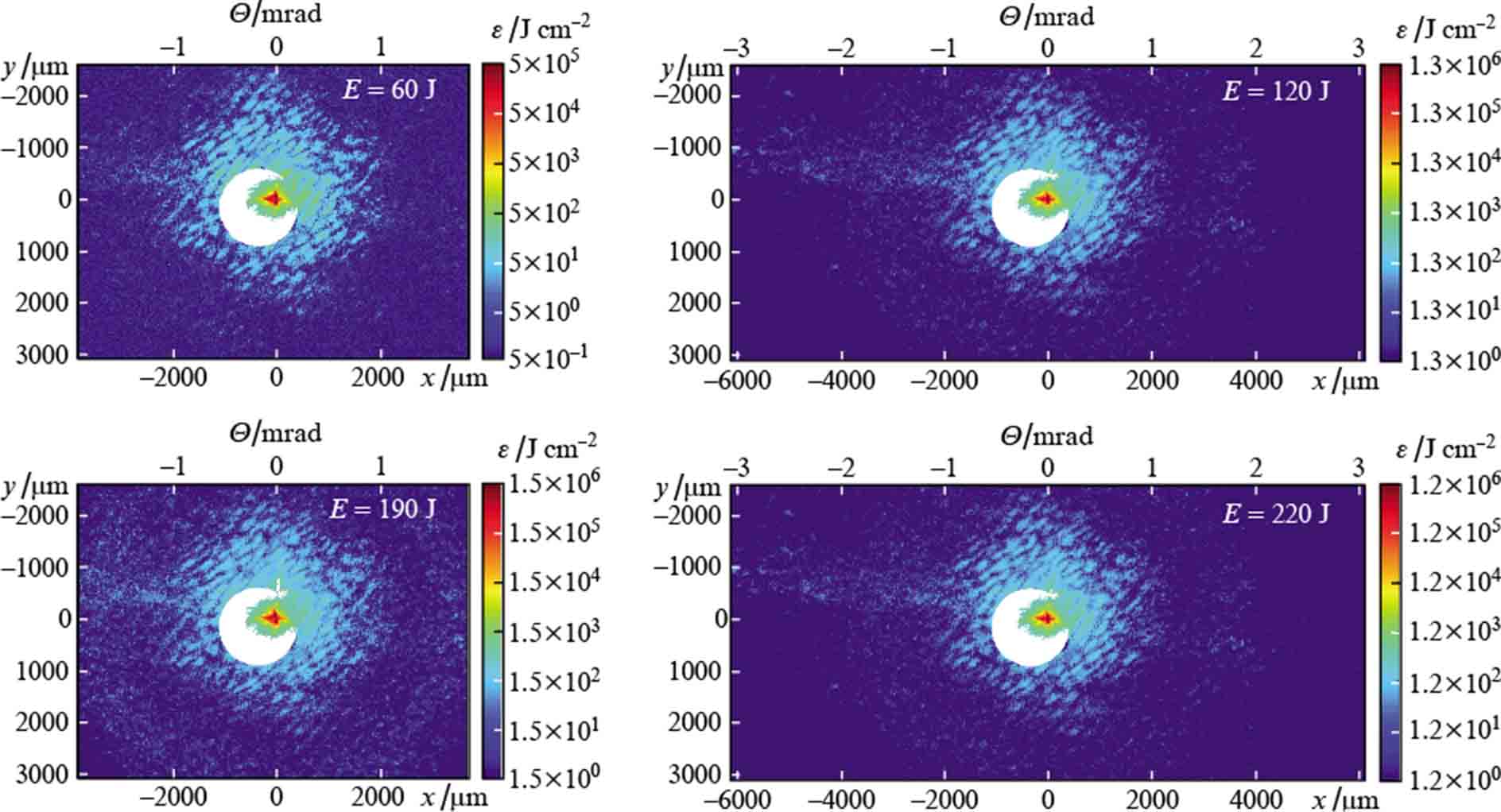
Figure 2. (Colour online) Energy density distribution ε in the focal plane of a spatial filter SF at different energies E of laser pulses; Θ is the azimuthal angle.
Download figure:
Standard image
Figure 3. (Colour online) Radial energy density distributions ε in the focal plane of spatial filter SF averaged over the azimuthal angle Θ.
Download figure:
Standard imageOne can see from Figs 2 and 3 that increasing the pulse energy results in the manifestation of a far-field ring structure arising from small-scale self-focusing due to cubic nonlinearity. In accordance with Ref. [23], the maximum of spatial perturbation enhancement is observed at an azimuthal angle Θmax = (2n0 n2 I)1/2, where I is the intensity of laser radiation, n0 is the linear refractive index, and n2 is the nonlinearity coefficient. In the focal plane of the SF telescope, the angle Θmax corresponds to the spatial scale rmax = F Θmax, where F = 2 m is the focal length of the telescope lens. The Θmax values indicated in Fig. 3 were calculated for n0 = 1.58, n2 = 3.2 × 10⁻⁷ cm2/GW (phosphate neodymium glass) and a beam diameter of 83 mm at the input of the SF. It is evident that the angles Θmax are in good agreement with the positions of the maxima of the experimental curves.
For Θ ≪ Θmax, the effect of small-scale self-focusing is small, but the energy density distributions in the far-field zone still differ from those for diffraction-limited beams due to aberrations of the optical elements of the laser, mainly due to spherical aberrations of the lenses of spatial filters. The results of calculation with the inclusion of spherical (and only spherical) aberration of all lenses of the optical path are shown in Fig. 4, which also shows the distribution for an aberration-free beam with a flat phase at the input of the SF. The field amplitude at the input of the SF in these calculations was borrowed from the measured energy density distributions in the near-field beam zone, and the amplitude of the spherical aberration was approximately 4π, i. e. the associated addition to the radiation phase  , where RA = 5 cm is the radius of the A100_2 amplifier.

Figure 4. (Colour online) Energy density distributions in the focal plane of a telescope SF: experimental and theoretical distributions for an aberration-free beam and for a beam with the spherical aberration accumulated in all lenses of the optical path.
Download figure:
Standard imageFigure 4 shows that the main contribution to the lowering of the Strehl number (to ∼ 0.15) is made by spherical aberration. For r < 330 μm, the experimental data coincide reasonably well with the data calculated with the inclusion of spherical aberration. At large r, the experimental dependences are higher than the theoretical ones due to the laser beam scattering from defects in optical elements, such as dust, scratches, surface roughness, and optical breakdowns. This is precisely the domain where our selected value of the pinhole radius Rd of the spatial filter SF (Rd = 0.45 mm) is located. Therefore, the main role in the plasma production at the edge of the pinhole is played by the laser beam components scattered by defects of optical elements, and not by the aberrations of optical elements.
Figure 4 also shows that even a several-fold increase in the radius of the pinhole will not entail a significant decrease in the radiation intensity at its boundary. Nevertheless, increasing the pinhole lengthens the time taken to fill it with plasma and, therefore, improves the conditions for the passage through the spatial filter of two pulses propagating one after another with a certain delay.
To what values can the pinhole radius be increased? Obviously, the pinhole should cut off the most rapidly growing parts of the angular spectrum of the beam. As follows from Fig. 3, this goal will be met by pinholes with a radius of up to 2 mm, which cut off all noise components with Θ > 1 mrad. However, noise with smaller Θ angles, although weakly enhanced due to self-focusing, is also responsible for near-field beam modulation. The pinhole should smooth out such modulation to an acceptable level, so that the intensity of laser radiation after amplification in the next active element does not reach the breakdown threshold of the active medium.
As suggested by estimates of the plasma velocity (see Section 2), for a free passage of the second (delayed by 1.8 ns) pulse through the spatial filter for an energy of the first pulse of 220 J, a pinhole with Rd > 0.55 mm is required. The aim of the experiments described in the next Section was to obtain two approximately equal pulses with maximum energy without locking the spatial filter SF. For this purpose, we made a pinhole with a radius Rd = 0.8 mm.
4. Passage of two pulses through a spatial filter for different pinhole radii
We compared three configurations of the spatial filter SF: with a pinhole radius of 0.45 mm, a pinhole radius of 0.8 mm, and without a pinhole. The A100_2 amplifier was not pumped in these experiments. Figure 5 shows the pulse waveforms and the transverse near-field energy density distributions at the SF output. The first-to-second pulse energy ratio at the output of the master oscillator was about 1 : 4. The waveforms were measured using fast photodiodes and an oscilloscope with a bandwidth of 2 GHz. Their combined pulsed response had a duration of about 300 ps. Note that, although both pulses arrived at the same photodiode, it is incorrect to judge their power ratio by the oscillogram, since the pulse attenuation coefficients were not the same.
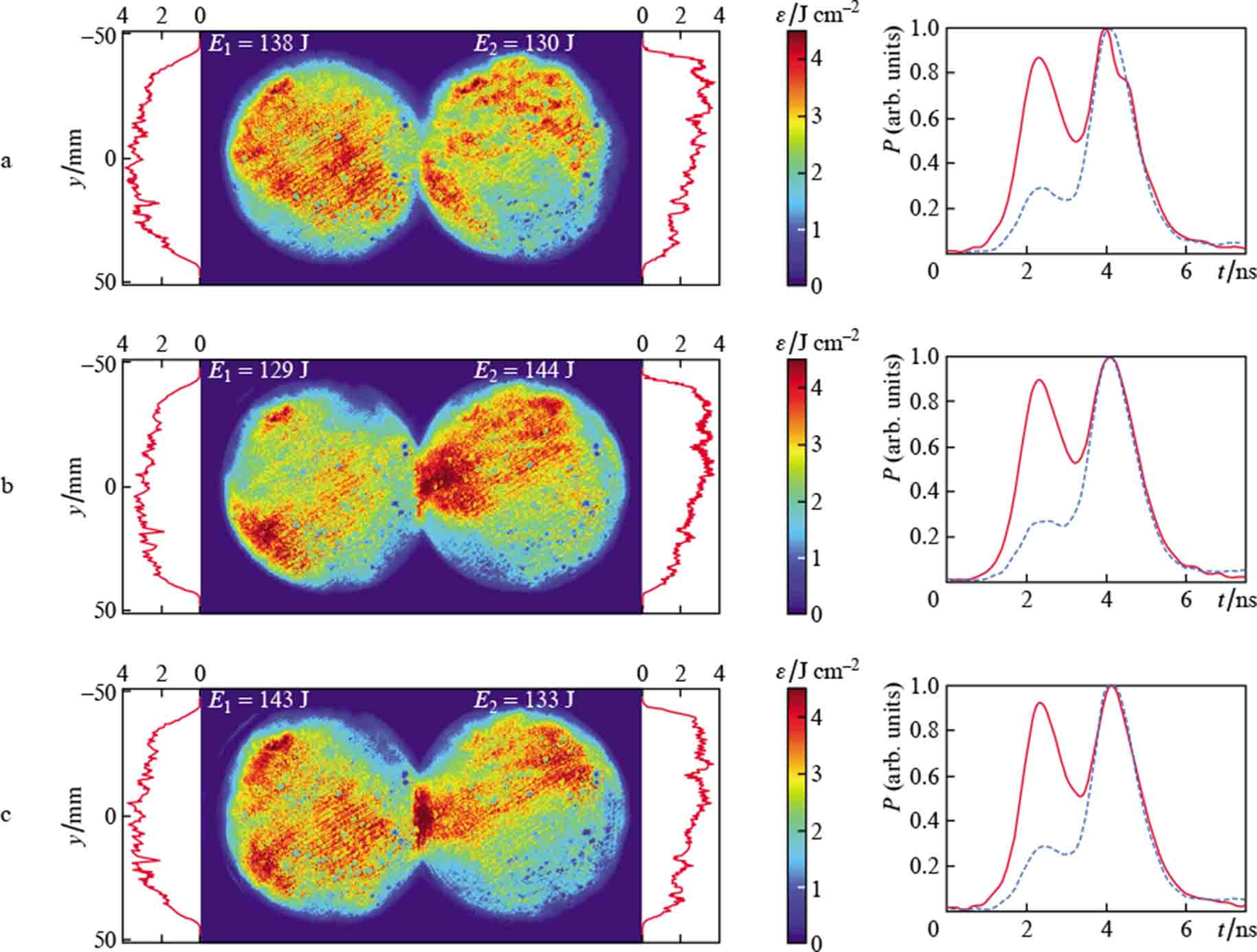
Figure 5. (Colour online) Energy density distributions for the first and second pulses at the output of the SF and pulse power oscillograms P at the same point (solid curves) and at the output of the master oscillator (prior to amplification in the neodymium glass) (dashed curves) for SF pinhole radii of 0.45 (a) and 0.8 mm (b) as well as without a pinhole (c).
Download figure:
Standard imageIn Fig. 5a, one can see additional modulation in the transverse distribution. Furthermore, there is a spall on the waveform of the second pulse immediately after its maximum. Both the spall and the modulation testify to the scattering of the radiation of the second pulse in the plasma produced in the vicinity of the pinhole. The plasma-induced effect on the second pulse was not observed in the experiments with a large pinhole (Fig. 5b) and without it (Fig. 5c).
After the SF, the pulse with an energy of about 140 J was further amplified to about 250 J in the A100_2 amplifier (Fig. 6a). The data shown in Fig. 6a did not depend on what pinhole was in the SF telescope, which cannot be said about the intensity distribution in the far-field zone. Figure 6b shows the far-field energy density distributions ε(r) averaged over the azimuthal angle and the cumulative energy distributions

for different configurations of the spatial filter SF (here, r0 = 0.8 mm is the radius of the largest pinhole under consideration). Comparison of the curves in Fig. 6b leads us to an unexpected, on the face of it, conclusion: the use of a pinhole with a smaller radius gives a greater high-frequency spatial noise. This is attributable the fact that plasma scattering near the edge of the smaller pinhole causes greater noise at high spatial frequencies due to two reasons. First, because the energy of the scattered field is higher, and second, because the hotter plasma produces stronger pulse scattering. Therefore, even for the first pulse, it is more advantageous to use a larger pinhole.
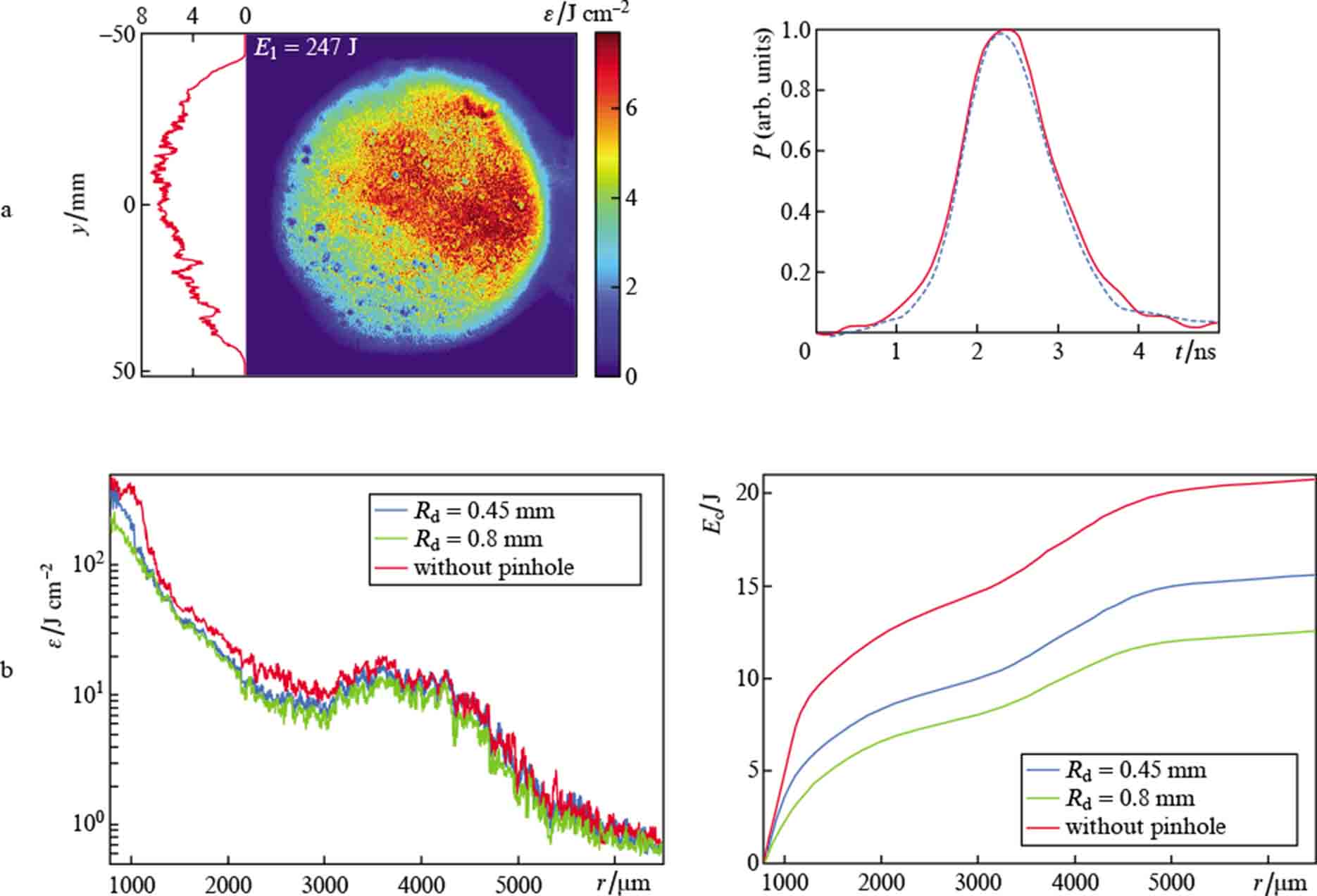
Figure 6. (Colour online) Near-field energy density distribution after the A100_2 amplifier and pulse power waveforms at the output of the master oscillator (3 mJ) (dashed curve) and of the A100_2 amplifier (solid curve) (a), as well as far-field distributions of the energy density and cumulative energy Ec after the A100_2 amplifier for two radii of the pinhole in the SF spatial filter and without the pinhole (the spatial scale corresponds to the scale in the focal plane of the SF telescope, shown are the radial dependences outside of the pinhole of radius 0.8 mm) (b).
Download figure:
Standard imageAfter the SF, the maximum total energy in our experiments amounted to 290 J. Higher values could not be obtained due to the master oscillator (see Fig. 1), after which the total energy of the pulses did not exceed 3 mJ. Additional pulse amplification in the A100_2 amplifier makes it possible to obtain a total radiation energy of more than 400 J. This is illustrated in Fig. 7, which shows the pulse energy at the output of the SF telescope (ESF) and of the A100_2 amplifier (EA100_2) against the energy at the output of the master generator (EMO). Note that in our experiments the energy density did not exceed 8 J cm−2, i. e. was slightly below the optical breakdown threshold.

Figure 7. Pulse energies at the output of the spatial filter SF (ESF)) and at the output of the A100_2 amplifier (EA100_2) against the energy (EMO) at the output of the master oscillator: experimental points and trend lines.
Download figure:
Standard imageIn accordance with the Franz – Nodvik formula, the energy dependences shown in Fig. 7 do not depend on the pulse duration. In particular, they are the same both for one pulse and for two consecutive pulses; in the second case, we are talking about the total energy of the pulses. Therefore, if the pulses are divided into two channels by a polarizer after the SF telescope and an additional amplifier A100_2 is used in each of them, then pulses with an energy of 250 J will be obtained in each channel, which we demonstrated by the example of only the first pulse (see Fig. 6). If the division into two channels is carried out after the A100_2 amplifier (as in Fig. 1), then two pulses with energies of 200 – 220 J each are obtained at its output. This repeats the results of our previous work [15], but for a new and twice as compact configuration with short spatial filters, whose locking problem has been solved.
5. Conclusions
In the optimisation of large facilities like the PEARL laser facility, there inevitably arise difficulties which call for compromise solutions. Previously, we shortened the vacuum spatial filters, which made the pump laser of the PEARL facility twice as compact. However, due to the increased intensity of laser radiation at the edges of the pinholes of spatial filters, the implementation of our idea of amplifying two successively propagating pulses in one laser shot revealed the problem of locking the spatial filters for the second pulse due to the formation of a plasma plume in the focal waist domain after passage of the first pulse through it. We studied in detail the intensity distribution in the plane of the pinhole of the most-loaded spatial filter and determined the admissible size of the pinhole, which makes it possible, on the one hand, to cut off the dangerous parts of the angular spectrum of the laser beam from the point of view of small-scale self-focusing, and on the other hand, to pass two nanosecond pulses with a delay of 1.8 ns without scattering of the second pulse by the ablation plasma. The optimal pinhole permitted the passage through the spatial filter of two pulses with an energy of 130 – 140 J each, which, after amplifying the pulses in standard neodymium glass amplifiers with a diameter of 100 mm, gives an energy of each pulse of about 250 J.
Acknowledgements
This work was supported by the Ministry of Science and Higher Education of the Russian Federation in the framework of financing the 'Photonics Centre' World-Class Science Centre (Agreement No 075-15-2020-906 of 16.11.2020).