
Abstract
Additive manufacturing for microfluidics shows potential to boost research and development in research biology and molecular diagnostics. This paper reports on novel process and material optimisation techniques in the creation of a monolithic microfluidic chip geometry for polymerase chain reaction (PCR) thermocycling using stereolithography (SLA). A two-stage printing protocol with projection SLA is assessed in printing disposable oscillating-flow microfluidic cartridges for PCR. Print performance was characterized in terms of critical channel dimensions and surface quality. Post-treatment with ultraviolet light and solvent washes was shown to reduce PCR inhibiting residuals and facilitate the reaction, indicating material compatibility for fluidic and milli-fluidic PCR architectures. Residuals leaching from the polymer were shown via quantitative PCR that interact with enzyme activity. Passivation of channel surfaces with a polyethylene glycol and a silane static coating reduced the leaching interface improving overall PCR efficiency. The discussed protocols can serve as a low-cost alternative to clean-room and micromachined microfluidic prototypes for various microfluidic concepts.
Export citation and abstract BibTeX RIS

Original content from this work may be used under the terms of the Creative Commons Attribution 4.0 license. Any further distribution of this work must maintain attribution to the author(s) and the title of the work, journal citation and DOI.
1. Introduction
Miniaturization of nucleic acid amplification on a microfluidic device was introduced in the early 90s [1, 2]. This was due to the multiple benefits in terms of reagents costs, performance and capability for higher-throughput, on a small device that incorporates all necessary steps, particularly important feature for field testing [3]. Since then, numerous studies reported on complete nucleic acid testing systems, with some of them translated into commercial applications [4]. These lab-on-chip platforms incorporate microfluidic technology and microelectromechanical system components to perform complex, high-throughput operations with fluid samples, and have displayed outstanding performance compared to traditional lab-methods. Despite its breakthrough capabilities, lab-on-chip technology has developed slowly [5, 6]. Several studies argue that the lack of a critical application meant that the technology was not developed further [7]. Nonetheless, high expertise and costs involved in microfluidics prototyping, limited communication of research needs between biologists and engineers [6] and strict regulatory frameworks for healthcare manufacturing, all slow down research and development in microfluidics [8, 9]. Point-of-care nucleic acid testing typically relies on nucleic acid amplification by polymerase chain reaction (PCR) performed on a microfluidic device. PCR is based on the in vitro enzymatic exponential amplification of a target nucleic acid sequence, through a thermal cycling process of purified template DNA in the presence of additional polymerase enzyme, nucleobases and primers suspended in an aqueous buffer solution. To perform PCR on a microfluidic chip, certain design patterns may facilitate all steps, from nucleic acid extraction, sample preparation, thermocycling and detection, by means of filtering, gradual mixing of reagents and thermal cycling [10]. The microfluidic thermal cycling approach determines the channel geometry at a great extent. Two different approaches are usually employed: flow-through thermocycling and stationary. The former refers to the passive exchange of heat of a fluid sample that flows through regions of a channel with different temperature. The latter refers the use of active heating/cooling elements to manage thermocycling. Flow-through approach is significantly faster due to the high surface-to-volume (SVR) ratio channels, while the use of pumps to facilitate flow enables easier integration of additional fluid management steps that can increase functionality and throughput [11]. However, flow-through architectures can be highly complex and expensive to manufacture, particularly in low volumes which discourages experimentation. Currently, low and medium volumes of microfluidics are manufactured with clean-room processes, such as photolithographic patterning and wet/dry etching of silicon, glass and/or polymer parts [4]. Higher volumes are typically produced with microscale versions of forming processes, such as injection moulding or hot embossing of biocompatible thermoplastics. Micro-forming can be prohibitively expensive for prototyping, due to tool manufacturing, while clean-room processes also require tooling and expensive set-ups. For this reason, prototyping typically relies on mechanical and laser micromachining of various polymers, glass or silicon and/or soft lithography of polydimethylsiloxane for manufacturing [12]. In the last decade, 3D printing of microfluidics attracted scientific attention, due to its open-source nature, low set-up and running costs and tool-free geometrical complexity not found in conventional processes [13]. A high-resolution resin 3D printer costs less than £3000 and can be easily integrated in a basic laboratory set-up, enabling functional prototyping without extraordinary costs associated with workshop or clean-room manufacturing [14]. As a result, several studies reported cost-efficient 3D printing of microfluidics for molecular biology and biochemistry [15–17], as well as tools for soft lithography [18]. Most studies relied on resin-based inkjet-3D printing (polymer jetting) and stereolithography (SLA), which offer the highest resolution among the entire family of additive manufacturing (AM) processes, apart from two-photon lithography [19, 20]. There are two main challenges associated with resin-based microfluidics prototyping for biology and medicine: biocompatibility of prints and manufacturability of channels [21].
1.1. Biocompatibility of 3D printing resins
Photo-curable resins are typically acrylate and/or epoxy derived monomer and oligomer formulations that are cross-linked upon exposure to ultraviolet (UV) light [20, 22]. Monomers and oligomers are highly cytotoxic for most types of mammalian cells [23] and PCR inhibiting [24, 25]. These can leach from the printed polymer and interfere with vital biochemical reactions in a biological process, such as cell proliferation and differentiation [26] and enzymatic nucleic acid amplification [25]. Biological compounds can further interfere with the printed surface leading to their adsorption. In high SVR microfluidic architectures, surface interactions can have detrimental effect in the outcome of a reaction. Basic post-processing protocols for photopolymer prints include solvent washes, thermal and post-UV curing, with all approaches aiming to reduce print residuals [27]. Appropriate post-processing of resin prints has been shown in multiple cases to enable applications such as cell and bacteria culture [26, 28–30] and PCR [24, 31, 32]. Furthermore, commercially available biocompatible (USP Class IV) SLA resins have been tested in low-risk applications such as skin and internal tissue contact for hearing aids and dental inserts, short period bacteria and/or cell cultivation experiments [33, 34]. Highly biocompatible and biodegradable photo-curable formulations for tissue engineering applications have also been reported [35–39]. The intrinsic reactivity of photopolymers further enables static or dynamic coating of various biocompatible agents on 3D printed channels to improve performance. Coating agents such as silanes [4], polyethylene glycol (PEG) [31, 40], serum albumin (BSA) [31, 41], polyvinylpyrrolidone, hydroxyethylcellulose [42], polyvinyl alcohol [31] and formaide [4] have all been shown to reduce non-specific adsorption and facilitate cell and PCR compatibility in conventionally and additively manufactured PCR devices, including photopolymer prints [31].
1.2. Manufacturability of microfluidic channels with stereolithography
The minimum feasible size of a monolithic microchannel printed in SLA is determined by part orientation, channel pattern and resin viscosity [43], along with the print resolution as defined by laser beam (SLA) or pixel size in case of Digital Light Processing (DLP) SLA technology.
The current mature 3D printing methods with SLA cannot realise very complex patterns, as uncured resin cannot be efficiently removed from complex microchannels. Hence, 3D printed microfluidics often display limited functionality [21]. Even with low viscosity resins, drainage issues limit design freedom, while most heat resistant SLA resins for thermal cycling applications are high viscosity, due to the high molecular weight monomers and oligomers content. Design for drainage practices, optimum model orientation [44], channel feasibility studies and low viscosity resins [15, 45] are some techniques that partially address this issue, although compromise design flexibility. To realise enclosed channels, different groups employed multi-step printing practices [31, 46, 47]. For instance, Hutchinson et al reported the use of sacrificial wax for layer-by-layer photolithographic patterning of photo-definable monomer [47]. The process was manually performed layer-by-layer and is mentioned as contact liquid photolithographic polymerization (CLiPP). Elements of it were patented in 2003 [48]. Yin et al established specific protocols to remove sacrificial wax from inkjet-3D printed channels in complex 2D patterns [49], a protocol that was subsequently employed for printing droplet-based PCR chips [32]. To circumvent resin drainage issues, Büttner et al demonstrated a single layer exposure method based on DLP projection for printing complex channels with heights of 25–150 μm on polymethyl methacrylate (PMMA) or glass substrates [46]. Another recent work on manufacturability of microfluidics with DLP SLA was demonstrated by Bazaz et al [50]. The group printed open channel microfluidic parts which were then bonded on PMMA sheets with pressure sensitive tape. In this way, the group produced various inertial microfluidic devices with application in particle and cell separation. In other work, Kadimisetty et al [31] designed and printed two separate microfluidic parts with SLA to assemble them into a micro-reactor array for isothermal nucleic acid amplification. The two-part assembly enabled the integration of membranes for DNA extraction, while offered sufficient convenience for resin drainage after printing. Ruiz et al used a hybrid SLA–FDM (Fused Deposition Modelling) printing approach to print polymethacrylate-thermoplastic polyurethane elastomer devices. Polyurethane elastomer provided leak-free bonding and pumping functionality [51]. The works of Hutchinson et al [47] and Yin et al [49] produced successful results in context of manufacturability for complex channels with sacrificial material. However, similar approaches with sacrificial material has not been seen for the lower-cost DLP SLA. Different approaches to print enclosed microfluidics with DLP SLA [46, 50, 51] have produced successful results in their field of applications, however the main drawback lies on the use of adhesives sheets that introduce material inconsistency in the channels and impose multi-step processing.
Improvements in the 3D printing technology and materials is anticipated to yield further advancements in several research fields, including microfluidics [52, 53]. It has been argued that with proper bonding methods and successful addressing of the biocompatibility factor, resin-based 3D printing displays great potential as prototyping techniques for lab-on-chip platforms [30, 54, 55]. Yet, specific, standardized and scalable processing protocols, manufacturability issues, repeatability of prints, integration and performance of 3D printed devices in key microfluidic case studies are not developed in detail [53, 56, 57].
Towards this end, this paper reports on novel process optimisation techniques in the creation of monolithic microfluidic channels and geometries for PCR thermocycling using SLA. To deliver enclosed serpentine microchannels with DLP SLA, a two-stage printing method was developed and assessed in printing of several replicates of an oscillating-flow microfluidic geometry for two-step PCR thermocycling. The suggested printing method employs sacrificial wax, which enabled complex channel patterns that are not feasible at a single print step. The effect of the post-processed material in PCR was assessed by mock PCR reactions and quantitative PCR (qPCR) analysis of leachates from printed chips, retrieved from simulated thermocycling experiments on a custom-built thermocycler. To improve material performance, PEG and silane coatings were developed as dip-coating methods, evaluated, and implemented as perfusion coatings in 3D printed chips. Leachates from functionalized chips were assessed in qPCR and compared to those retrieved from non-treated chips. The efficiency of printing, post-processing and surface treatments are discussed and the overall potential of DLP SLA to advance the microfluidics field is summarized.
2. Methods
2.1. DLP SLA printing
Printing experiments were performed on an Autodesk Ember commercial DLP SLA 3D printer. The system projects high-definition patterns in 405 nm (27.5 mJ cm−2) UV light with a 50 μm pixel resolution on a maximum build area of 64 × 40 mm. Layer height (z) resolution was 50 μm. To print the mock PCR specimens and PCR chips, Formlabs Hi Temp SLA resin was selected, due to its high temperature resistance and good optical transparency. According to manufacturer, the printed and post-UV-cured parts exhibit can withstand temperature up to 289 °C with minimum deformation. All prints were basically post-processed by washing in isopropyl alcohol and UV cured for 1 h under a 355 nm, 80 W cm−2 source before any further post-processing as described in sections 2.2 and 2.3. The printing process was programmed in Autodesk PrintStudio.
2.2. Interference of printed polymer with PCR: low surface-to-volume prints
To simulate the material behaviour of a low SVR 3D printed fluidic device and characterize its PCR performance in vitro, low-volume printed specimens were exposed to PCR mixture during amplification reactions that were performed conventionally. The specimens were post-processed at different extents to evaluate the efficiency of post-processing to reduce PCR inhibiting residuals. Prior to PCR sample preparation, nine cubes (1 mm3) were printed, washed in isopropanol, dried with air and post-cured in a UV oven (0.08 W cm−2, 355 nm) for 1 h. Three cubes were placed in individual PCR tubes and sealed. The remaining six cubes were boiled and stirred in 100 ml deionized water. Three more cubes were placed in PCR tubes and sealed. The final three cubes were boiled in deionized water for 1 h and simultaneously exposed to UV light. They were then stored in PCR tubes and sealed. A PCR protocol to amplify a 1000 base pair long target was used for characterization. PCR mixture for nine reactions, three replicates for each post-processing condition, plus three controls was prepared. Each individual reaction contained 50% v/v FailSafe® PCR buffer Premix D (Lucigen) with 4 mM MgCl2 and 400 μM of each deoxyribonucleotide triphosphate (dNTP) (10 μM), 5% v/v of each primer (SeCopA P1 forward TGTCAATGAATTGATGACCAATCATAAAGGAGTTTT-TACTTGTAGGCTGGAGCTGCTTCG 10 µM and SeCopA P2 reverse CCGCCTTTAAGCAACTCGAATTATTTTGGGTATAGACTTTCATATGAATATCCTCCTTAG 10 µM), 1% v/v Taq DNA polymerase and 1% v/v plasmid DNA template solution (30 ng μl−1) in molecular biology grade water. The reaction mixture was pipetted into the tubes, which were gently mixed, pulse spun and ran in a BioRad PCR thermocycler (figure 3(a)). The thermocycling protocol included an initial denaturation step at 95 °C for 5 min, followed by denaturation at 95 °C for 30 s, annealing at 52 °C for 30 s and extension at 68 °C for 60 s repeated for 35 cycles with a final extension step of 5 min. After thermocycling, the contents were resolved in a 1% (w/v) agarose gel for 35 min at 90 V, with a 10 µl of DNA ladder and imaged on a UV transilluminator.
2.3. Interference of printed polymer with PCR: high volume-to-ratio prints
To simulate a high SVR microfluidic architecture, a specimen of the same active 'wet' area (349 mm2) to the oscillating-flow PCR design (figure 1(a)) was designed to fit in a PCR polypropylene tube (figure 3(c)). The specimens were printed and fully post-processed to the last step detailed in section 2.2 with water washes and prolonged UV curing. Incubation of the specimens with PCR buffer–dNTPs–MgCl2 mixture (FailSafe® PCR, Premix D, Lucigen) and use of the mixture for subsequent PCR, allowed the extraction of conclusions regarding potential leachates from the printed polymer with PCR inhibiting behaviour, as well as adsorption of dNTPs and Mg ions. The direct incubation would restrict reagents mobility and introduce PCR inhibition irrelevant to material. Four specimens were added to individual PCR tubes. Fifty microlitres of buffer premix was added to each of the tubes, which were refrigerated for 23 h. Two tubes were further incubated at room temperature (RT) and the remaining two at 95 °C for 1 h. After incubation, 25 μl of each buffer was used to prepare two 50 μl reactions for each representative case, according to the PCR protocol described in section 2.2. The amplified samples were resolved on a 1% w/v agarose gel in Tris-acetate-Ethylenediaminetetraacetic acid (TAE) buffer at 90 V for 35 min. The gel was imaged on a BioRad transilluminator. It has to be mentioned that the experiment neglects PCR inhibition sources associated with fluid flow in flow-through PCR systems and is mostly representative for stationary PCR.

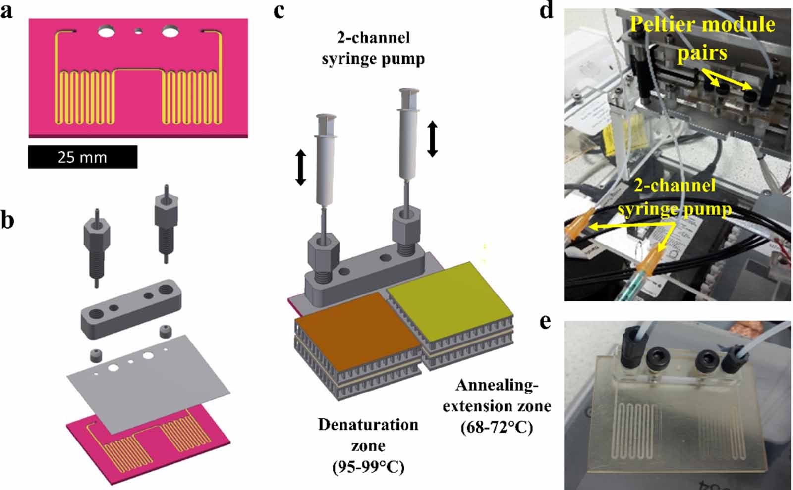
Figure 1. Microfluidic chip and set-up for two-step PCR thermocycling. (a) Open channel chip geometry with serpentine channel of 400 × 700 μm. (b) PCR chip 3D model assembly consisted of: open channel chip and cap, chip manifold, microfluidic fitting nuts, 1/16'' tubing and ferrules for chip interfacing. (c) Schematic of the two-step PCR thermocycling set-up for a 3D printed chip. (d) Chip mounted on the PCR thermocycling set-up. (e) PCR mixture pressurization and positioning prior to PCR.
Download figure:
Standard image High-resolution image2.4. Chip design and manufacture
2.4.1. Model chip design.
A two-step oscillating-flow thermocycling architecture was developed, consisted of a microchannel extending in a serpentine pattern over two distinctive regions. The chip was designed for mounting between a pair of individually controlled Peltier elements. Once the chip is mounted on the two Peltier pairs (set at 95 °C for denaturation and at 68 °C for annealing-extension steps) and reach a temperature equilibrium, the fluid that flows through each region, rapidly exchanges heat with the chip material and subjected to thermocycling. The period of a thermocycling step is therefore dependent on the time that the fluid is held over a specific temperature region. The full two-step PCR thermocycling methodology is analysed in section 2.10. The chip design consisted of an open channel chip and a cap with 500 μm inlets. The open channel was a 400 × 700 μm cross-section channel extending over a 51 × 38 mm area on the chip in a serpentine pattern (figure 1(a)). The 'wet' channel area is approximately 349 mm2 and accommodates 50 μl reactions. Nominal cap and chip thickness were equal to 0.2 mm and 0.6 mm, respectively. A manifold design was developed to interface the produced chips with market available 1/16'' and 1/8'' tubing and M6 microfluidic fitting nuts (figures 1(d) and (e)).
2.4.2. Chip fabrication.
A two-stage printing method with use of sacrificial wax was implemented (figure 2(a)). Initially, an open channel chip was regularly printed, positioned (in AM software) parallel to the projection plane without supports. To calibrate the printer before a print, the platform's ball screw is loosened and lowered towards the transparent window of the resin tray over the projection area, leaving a thin resin layer between them. The platform is then tightened in position and an open channel chip is printed. After printing, the platform was removed, and the open channels were cleaned with isopropanol and dried before applying sacrificial paraffin wax (melting point: 53 °C–57 °C (ASTM D 87), Sigma-Aldrich). The cleaning and wax deposition process occur with the printed part held on the platform. The second step of fabrication is a tedious manual operation and requires careful application of wax in the channel cavities and removal/cleaning from the face of the chip to avoid leakage issues. After careful cleaning and ensuring that wax has filled all channel cavities, the platform was placed back on the printer and was recalibrated, following the standard calibration procedure. A cap 3D model, virtually positioned at the same x–y coordinates with the previously printed chip, was then printed onto the existing chip, sealing the channels. The angular position of the platform was monitored from the first stage of printing and maintained for the second, so that inlets on the cap align with the channel ends. Given that no wax residuals are present in the face of the chip, the part sticks properly to each other as they are composed from the same photopolymer at its semi-polymerized state.
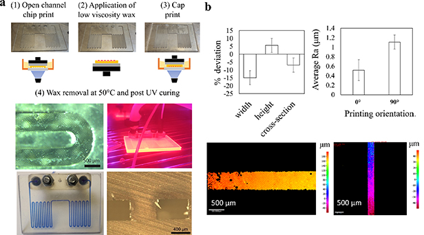
Figure 2. (a) Two-stage printing of 2.5D channel patterns with DLP SLA. An open channel chip is printed with no supports (1), cleaned, and filled with sacrificial wax (2), before a cap is printed on the open channel chip (3) and seal the channels. The chip is then heated to flush wax away and UV cured (4). (b) Deviation of critical channel dimensions from nominal, (c) average surface roughness of channel wall printed horizontally and vertically to the DLP projection plane, height maps of (d) horizontally and (e) vertically printed channel walls.
Download figure:
Standard image High-resolution image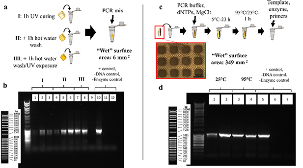
Figure 3. Interference of printed polymer with PCR. (a) Low SVR printed specimens (cube), previously post-processed at different extents are incubated with PCR mixture during the reaction. (b) Gel electrophoresis imaging of PCR products incubated with low SVR specimens. Samples post-processed with UV light and hot water washes (groups II and III, bands 4–8) showed minimum interaction with PCR, compared to the ones post-processed only with isopropanol washes and/or UV curing (group I, bands 1–3). Faint amplicon generation in band no 4, as opposed to the rest of the bands in groups II and III is attributed to errors in pipetting and loss of amplicon during loading. (c) High SVR printed specimens are incubated with PCR buffer–MgCl2–dNTPs mixture to evaluate inhibition due to leachates from the prints and/or adsorption of Mg ions or dNTPs. (d) Gel electrophoresis of PCR products from incubated with high SVR specimens. No leachates from the printed polymer interfered with DNA amplification (bands 2–4), in comparison with the positive control (band 5), while negative control reactions lacking template DNA (band 6) and polymerase enzyme (band 7) generated no product.
Download figure:
Standard image High-resolution imageAfter a chip was printed, it was removed from the platform, washed in isopropanol and dried. It was then submerged in hot water, to melt the wax and flush it out using a syringe with hot water and isopropanol. The total time for fabrication of a non-post-processed part was 5 min for 0.8 mm (nominal) thick chips. The raw material cost per chip was calculated at approximately £0.25, considering 1.5 ml resin/chip and £170 l−1 of resin. By using commercial microfluidic tubing and fittings, channels can be internally washed and treated by wet methods. For this work, eight chips were printed and fully post-processed as described in section 2.4.3.
2.4.3. Chips post-processing.
The post-processing steps evaluated in sections 2.1 and 2.2 were implemented for the 3D printed chips. After printing, chips were UV-cured (0.08 W cm−2) and washed internally with hot water for 1 h. To wash the channels internally, the chips were connected to a peristaltic pump with the use of a manifold (figure 1(b)). Inverted cone polypropylene fitting nuts with M6 thread (Kinesis, Cole-Parmer UK) and silicone ferrules were used to interface the chips with 1/16 or 1/8 tubing and syringe or peristaltic pumps. Silicone tubing of 1/8'' was used for cycling solvents through the channels. Polypropylene tubing of 1/16'' was used to connect the chips with the two-channel syringe pump of the PCR thermocycler (figures 1(b) and (c)). During channel wash, the chips were transferred in the UV oven. After wax removal and post-UV curing, no leakage issues were observed either at the washing stage of the chips (using a peristaltic pump) or during pressurization and shuttling of the fluid stream back and forth in the simulated oscillating-flow PCR experiments (section 2.10). After post-processing they were dried, tagged with a unique ID and stored in aluminium paper. The total fabrication and post-processing time was approximated at 1.5 h, with the capability to process multiple chips. Out of eight fully post-processed chips, two were functionalized with fluorosilane and two with PEG as described in section 2.7.
2.5. Fluorosilane dip-coating treatment—base part for coating study
Three disks of 10 mm diameter and 1 mm thickness were printed in Formlabs Hi Temp resin and post-processed to the final step as described for the cube specimens in section 2.2. Siloxane pre-treatment: the disks were dipped individually and soaked in 20 ml of siloxane solution (Silester XAR) and left to dry in air for maximum 15 min before dipped into a solution of hydrolysed fluorosilane agent. Fluorosilane agent hydrolysis: the fluorosilane coupling agent (1H,1H,2H,2H-perfluorooctyltriethoxysilane, Sigma-Aldrich) was added to a 95:5 ethanol:deionised water solution yielding a 2% v/v concentration. Prior to the addition of the fluorinated agent, the pH of the ethanol–water solution was adjusted with glacial acetic acid at 4.5–5.5. The fluorosilane solution was stirred for 5–10 min to instigate silanol formation. Fluorosilane treatment: samples previously treated with siloxane and dried were dipped and stirred for 2 h in the hydrolysed fluorosilane solution. They were then dried with air and treated thermally at 110 °C for 10 min and stored in petri dishes prior to evaluation with contact angle visualizations and scanning electron microscopy (SEM) imaging. Characterization: water contact angle was measured on a F-theta tensiometer using 0.05 μl deionised water drops. SEM–energy dispersive x-ray spectroscopy (EDS) analysis was performed on a Hitachi TM3030.
2.6. PEG dip-coating treatment—base part for coating study
Three disk specimens identical to those used for the fluorosilane modification were used for the PEG treatments. EDC/MES/NHS pre-treatment: three printed and post-processed disks were immersed in 20 ml of 6 M NaOH solution for 30 min. They were then rinsed with distilled water and dried with air. The disks were then pre-treated with an aqueous EDC hydrochloride (N-(3-dimethylaminopropyl)-N'-ethylcarbodiimide hydrochloride)/MES hydrate (2-(N-morpholino) ethanesulfonic acid hydrate, 4-morpholineethanesulfonic acid)/NHS (N-hydroxysuccinimide) solution. NHS/EDC/MES solution was prepared by dissolving 0.5 M MES hydrate in stirring deionised water. EDC hydrochloride and NHS were added into the MES solution yielding a 10 mM concentration, respectively. The disks specimens were dipped into the stirring solution for approximately 5 h. They were then washed briefly with distilled water and dried with air before treated with PEG. PEG treatment: PEG dipping solution was prepared by adding methoxypolyethylene glycol amine powder (molecular weight: 5000, Alfa Aesar) into stirring deionised water yielding a 1% v/w concentration. Disks pre-treated with EDC/NHS/MES were dipped into the stirring PEG solution for approximately 5 h. The samples were then dried and stored in a petri dish prior to evaluation with SEM–EDS and water contact angle measurements as described in section 2.5.
2.7. Fluorosilane and PEG perfusion coating of printed chips
A perfusion coating methodology was implemented to treat internally the microchannels. The fluorosilane and PEG coating and pre-coating solutions were prepared as described for the printed disk specimens. Fluorosilane perfusion treatment: a fully post-processed chip was filled with siloxane solution (Silester XAR) using a mechanical pipette, left for few minutes, and then thoroughly dried with pressurized air. The chip was then connected to the manifold and a single-channel syringe pump (PHD 4400 Harvard). Hydrolysed fluorosilane solution, prepared as described in section 2.5, flowed through the chip for approximately 2 h at low flow rates (0.1–1 ml min−1). For the last hour, the chips were mounted onto—the Peltier module pairs for the PCR thermocycler at 110 °C. PEG perfusion treatment: the EDC/NHS/MES solution was prepared as described in section 2.6. Similarly, the chip was connected to the manifold and the syringe pump and the solution flowed through the chip at 0.1–1 ml min−1 for approximately 5 h. After pre-treatment with EDC/NHS/MES complex, the chips were dried with air, connected to the manifold and syringe pump and treated similarly with the PEG solution for an additional 5 h.
For both types of functionalization, after the treatment was completed, they were disconnected from the manifold and thoroughly washed with PCR-grade water and dried with pressurized air. Particularly for the fluorosilane treatment, thorough cleaning is highly important due to the high toxicity and PCR inhibiting behaviour of residual siloxanes and hydrolysed fluorosilanes.
2.8. Dimensional and surface characterization
The critical dimensions and surface quality of the printed channels were evaluated by optical stereo and focus variation microscopy. Ten width and height measurements were conducted along the channel pattern for each of six chip replicates, retrieved from functional tests. Surface quality was evaluated by measuring average surface roughness on vertically and horizontally printed channel walls. For each of the cases, ten measurements were performed for six chip replicates along a 3 mm track on the printed channels. The top-channel wall formed during cap printing, possess surface roughness equal and inverse to the wax layer surface roughness. As wax deposition was performed manually, the roughness is not a process-associated variable and was not characterized in this work. To perform the measurements, chips were cross sectioned with a diamond coated disk cutter.
2.9. qPCR protocols in leachate analysis
To differentiate between inhibition due to surface interactions and chemical leaching, a qPCR testing methodology was used. PCR-grade water was thermally cycled according to a two-step PCR protocol in the 3D printed chip as described in section 2.10. In this way leachates from the chips were accumulated in water samples, subsequently used to prepare corresponding qPCR reactions. The real-time amplification data were compared to control reactions prepared with fresh water. Each qPCR reaction volume contained 20% v/v Phire buffer (5×), 200 μM dNTPs (10 mM), 0.5 μM v/v forward and reverse primer (SN086 forward TATGGGAAAGGTTCTGAA 10 μM, SN087 reverse TACAGATTGACTTCGATG 10 μM) respectively, 4% v/v human genomic DNA template (2000 copies μl−1), 5% v/v EvaGreen stain (20×, diluted with water to 1× final concentration) and 2% v/v Phire II hot start polymerase in the respective leachate water or fresh water for the controls. The reactions ran on a BioRad qPCR thermocycler, according to thermocycling protocol including an initial denaturation step at 95 °C for 300 s, following by denaturation at 95 °C for 10 s annealing at 50 °C for 10 s and extension at 72 °C repeated for 50 cycles.
2.10. Simulated oscillating-flow PCR
The oscillating-flow PCR thermocycler consisted of a two-channel syringe pump and a set of two Peltier elements for controlling chip fluid positioning and temperature, respectively (figure 1(c)). Fluid positioning and temperature was controlled through a National Instruments DAQ board and individual temperature controllers (CAL 3200, RS UK) in a Visual Studio application.
To simulate a two-step PCR protocol, a chip was loaded with 50 μl fluid sample (20% v/v glycerol in purified water) using a mechanical pipette and positioned in the denaturation zone. The chip was connected to the two-channel syringe pump through the manifold and 25 cm long 1/16 polypropylene tubing from both ends (figure 1(c)). One millilitre plastic syringes were used. The chip was then placed between the Peltier elements, so that each serpentine channel region is positioned within the active area of the heater. The chips were pressurized from both ends by positive syringe displacements to ensure that there are no leakages and the fluid stream hold its positioning without shuttering or drifting. The fluid was then pushed or pulled between each temperature region in the channel, by equal displacements of opposite direction for each syringe pump to perform two-step thermocycling. A full two-step PCR protocol ran with 80:20 water:glycerol with no leakages observed at the functional temperatures. The protocol included an initial denaturation step at 99 °C for 60 s, followed by denaturation at 99 °C for 5 s and extension annealing at 68 °C for 10 s repeated for 35 cycles. The total thermocycling time was 9.75 min. No deformations or material deterioration was observed for any of the printed chip replicates during or after thermocycling.
2.11. On-chip leach testing
To perform leach testing on a 3D printed chip, 50 μl PCR-grade water samples were thermally cycled according to a two-step PCR protocol for genomic template reactions as described in section 2.10. The water eluents were then collected and used to prepare representative qPCR reactions and record inhibition events. The values were compared to a positive control reaction ran conventionally. Four fully post-processed and non-treated, two fluorosilane-modified and two PEG-modified chip replicates were tested. The simulated oscillating-flow thermocycling protocol included an initial denaturation step at 99 °C for 60 s, followed by denaturation at 99 °C for 5 s and extension annealing at 68 °C for 10 s repeated for 35 cycles. The total thermocycling time was 9.75 min. After thermocycling, the chips were depressurized, and the water leachates were retrieved and stored. Three consecutive water samples of 50 μl were thermally cycled for each of the chips tested. The water eluents were then used to prepare PCR mixture for totally twelve 25 μl qPCR reactions as described in section 2.9.
3. Results
3.1. Printing performance
The width of the channels shows consistent negative deviation of −15% compared to the nominal value (0.4 mm) across six chip replicates. The printing accuracy is in agreement with common accuracy performance of DLP printers. Shrinkage of micro-features can also be attributed over-exposure of printed layers at the order of milliseconds. Lower levels of dimensional deviation were observed for channel height and cross-sectional area, approximately +5% and −5% respectively (figure 2(b)). The average surface roughness of a printed channel was 0.517 ± 0.221 μm at the bottom wall and 1.108 ± 0.149 μm on the side wall (figures 2(c)–(e)). This result displays the characteristic linear increase of surface roughness with print orientation angle in SLA prints.
3.2. In vitro characterization of interference of printed polymer with PCR
Reactions performed in the presence of low volumes of printed material, indicated that basic post-processing with only isopropanol washes and UV light (figure 3(b): bands 1–3) did not efficiently reduce PCR inhibiting residuals, judging from the fact that only a faint PCR product is visible. The reactions performed with printed specimens, previously post-processed with hot water and further UV curing (figure 3(b): bands 4–8) yield amplicon concentrations comparable to the positive control (figure 3(b): band 10), indicating the significant reduction of PCR inhibiting residuals after prolonged water washes of the prints. Negative control reactions lacking template DNA (figure 3(b): band 11) and enzyme (figure 3(b): band 12) respectively, did not generate any product. It must be mentioned that band no 4 (figure 3(b): band 4) shows faint amplicon concentration even though the reaction represents post-processing groups II and III that repeatably produced amplicons consistent with the controls. This is attributed to pipetting errors during loading of the gel that resulted in loss of amplicon. Higher SVR specimens were incubated with buffer–dNTPs–MgCl2 mixture at 25 °C and 95 °C. The reactions prepared with the incubated mixture produced agarose gel bands similar to the positive control (figure 3(d): band 5), that was prepared with fresh buffer mixture (figure 3(d): bands 2–4). This result indicates that no leachates from the prints exhibit a strong PCR inhibiting behaviour, while compounds such as dNTPs and Mg ions premixed into the PCR buffer are not absorbed. Negative control reactions lacking template DNA (figure 3(d): band 6) and enzyme (figure 3(d): band 7) respectively did not generate any product.
3.3. Fluorosilane and PEG treatment—evaluation of base parts
SEM–EDS analysis of the non-treated printed surface indicated the organic composition of the printed resin with the elemental signatures of carbon and oxygen only recorded (figures 4(a) and (b)). PEG-modified surface in EDS analysis indicated an increased oxygen content that reflects the oxygen-rich PEG and EDC/NHS/MES complex (figure 4(e)), but not obvious alterations were observed in the functionalized surface structure (figure 4(d)). Fluorosilane-modified specimens showed explicit alterations on the surface (figure 4(g)) with distinctive elemental signals obtained for silicon and fluorine (figure 4(h)), the main components of the silane agent. Non-treated samples displayed a slight hydrophobic behaviour with average water contact angle values of 80° (figure 4(c)). Fluorosilane-modified samples demonstrate values of approximately 115°, indicative of the fluorinated hydrophobic terminal portions of the silane agent (figure 4(c)). PEG-coated samples demonstrate a hydrophilic surface with water contact angle values of approximately 38° (figure 4(f)).
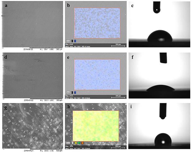
Figure 4. SEM images, elemental signatures, and water contact angle visualizations of the surface of the printed disk specimens in different treatment conditions. (a)–(c) Non-treated surface. (d)–(f) PEG-modified surface. (g)–(i) Fluorosilane-modified surface.
Download figure:
Standard image High-resolution image3.4. On-chip leachates qPCR analysis
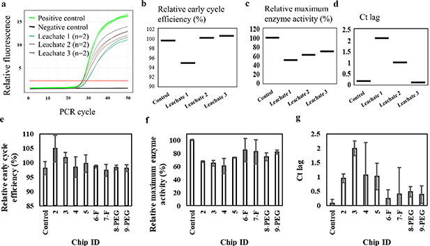
A representative amplification curve and the relative cycle efficiency, enzyme activity and Ct lag data for the first tested chip and three consecutive water leachates are presented in figures 5(a)–(d). Cycle efficiency values that exceed 100% indicate reduced enzyme activity owed to the presence of inhibitors in the water eluents. This imposes the requirement of more cycles to reach the threshold of detection compared to the control. This delay is recorded as cycle threshold lag. Interactions of ambient inhibitors with enzyme, apart from limiting its availability, can also result in non-specific target generation, as the enzyme fails to fully extend a target sequence in a given time period resulting in generation of shorter, non-specific sequences. For the reactions prepared with the second and third leachate water eluent for the same chip all values are improved and become more consistent with the control reaction. This indicates that washing of residuals is still ongoing, while water is thermally cycled into chips. An extended water wash period can be implemented for 3D printed chips based on this result, simultaneously studying changes in the material water uptake.
Figure 5. (a) qPCR amplification curves for three reactions prepared with three consecutive water eluents, previously thermally cycled on a printed PCR chip (chip ID: 1). Positive and negative controls ran with fresh PCR-grade water. (b) Monitored relative early cycle efficiency. Values over 100% indicate reduced enzyme activity and the presence of inhibitors. (c) Monitored relative maximum enzyme activity. Consecutive water leachates from the same chip showed variable enzyme activity that and cycle threshold lag that improved for consecutive washes. The third water eluent exhibited performance more consistent with the control. This indicates the need for further washing and/or surface treatment. (d) Cycle threshold lag (Ct lag) values, which are correspondingly reduced for each consecutive water leachate. (e) Data summary of qPCR inhibition analysis for water leachates from four non-treated, two fluorosilane and two PEG-modified printed chips.
Download figure:
Standard image High-resolution image
The qPCR analysis results for leachates from all non-functionalized, fluorosilane- and PEG-modified chips are summarized in figures 5(e)–(g). The modified cartridges, irrelevant to the modification method display improved overall PCR efficiency owed to the presence of lower inhibiting leachate content compared to non-functionalized cartridges. The relative early cycle efficiency values were kept close to, but not higher than 100%, similar to the values of the positive control, while enzyme efficiency and Ct lag values were improved compared to those of non-functionalized chips. Apart from reducing the leaching interface, functionalization shows promise for limiting adsorption during on-chip PCR.
4. Discussion
Several studies that report on microfluidics printing with SLA, concern enclosed simple channel patterns and micro-reactor geometries [15, 31, 58]. Their feasibility depends heavily on the channel pattern or rely on multi-part designs and processing steps for assembly. Assembly typically involves bonding of an open channel geometry with a transparent glass or plastic and/or adhesive sheet [32, 46, 50]. Some studies have previously reported the use of sacrificial wax for inkjet-3D printing [32] and the patented CLiPP process [47, 48] to create enclosed channels in photo-curable mixtures; although a similar approach has not been implemented for lower-cost DLP SLA. To 3D print unibody two-step PCR thermocycling microfluidic chips with DLP SLA, a two-stage printing protocol was used that involved the use of sacrificial wax. The benefit of the proposed two-stage printing lies on the capability to print functional unibody microfluidic prototypes in photo-curable resin of almost any 2.5D geometry and channel sizes down to few hundred microns. This dimensional range is common in microfluidics for medical diagnostics that process clinically relevant fluid volumes. Unlike similar attempts of printing microfluidics with DLP SLA [46, 50, 59], the cap and chip material are same material, which benefits from consistent surface properties. The latter are decisive in most biological microfluidic applications, while inconsistency might impair compatibility and performance of certain coatings. In addition, customized cap geometries are possible, which enables pseudo 3D channel networks by a 'chip stacking' printing method. The reported printing method delivers customized microfluidic prototypes at a small fraction of cost per chip when compared to alternatives, such as micro-milling, soft-lithography, injection moulding or photolithographic patterning of SU-8, but also material jetting 3D printing. However, the quality of prints in terms of accuracy and surface quality differed at a high extent from the well-established microfabrication methods. Printing accuracy, surface quality and repeatability data acquired from the DLP SLA printed chips show consistency with similar literature on DLP SLA printing performance in microfluidic features [14, 60]. The two-stage printing method did not significantly affect the accuracy of the printed channels since those are printed entirely during the first stage. Potential accuracy issues inflicted by cap printing would concern the z dimension of the channels. Dimensional error in the height of the monolithically printed channels is not altered compared to the inherent dimensional error of the process in microfluidic geometries [60]. Dimensional measurements were performed and treated statistically for different chip cross-sections and replicates, only after wax removal. Therefore, these results are representative of the final chip prototypes. As it was anticipated [61], surface roughness varied with the angle of printed wall relative to the projection plane with the rougher surface printed vertically (0.5–1 μm from 0° to 90°). As mentioned in section 2.4.2, the top-channel surface quality depends on the quality of the deposited wax layer. This was not evaluated as it was performed manually, and random error is introduced in the produced surface. Our group is currently working on automating wax deposition and patterning. Optimization of wax application is necessary to improve quality. The proposed method claims all the benefits of DLP SLA printing, which lie on low running and set-up costs, open-source character and faster production (compared to material jetting and extrusion AM) due to single layer exposure of DLP. The two-stage printing approach further solves manufacturability problems for complex channels and produced several functional microfluidic prototypes, faster than similar methods with sacrificial material to produce microfluidics in photopolymer resins [32, 47]. The process can be easily automated, by employing inkjet or extrusion technology to pattern sacrificial or further functional materials in a hybrid approach, adding value to the printed prototypes. Several geometries have already been tested using the proposed method, and it is considered that DLP SLA in such a hybrid manufacturing manner may reduce early prototyping costs for various microfluidic concepts and enhance research and development efficiency. In terms of compatibility of the high-performance resin with PCR, in vitro reactions show that residuals on the Formlabs resin prints interfere severely with the reaction, especially when prints are not sufficiently post-processed. Reduction of residuals by post-processing facilitates PCR compatibility for low SVRs producing amplicons consistent with the controls. High SVR specimens were incubated only with PCR buffer–dNTPs–MgCl2, due to their bulk geometry. Using this incubated mixture to prepare respective reactions, it was shown that leachates from high SVR prints have no significant influence in the PCR outcome, and components such as dNTPs and MgCl2 are not adsorbed into the polymer at an extent to cause suboptimal conditions. qPCR analysis of reactions prepared from leachate water eluents, previously thermally cycled in the printed chips, confirmed however that existing leachates do interfere with enzyme activity, decreasing the efficiency of the reaction [62]. This experiment studied inhibition due to leaching, free from other sources of inhibition, such as surface adsorption and/or poor thermocycling. The compromised enzyme activity due to leaching can affect not only the final target concentration, but also target specificity, especially for longer targets. This is due to the enzyme failing to fully extend a target sequence in a given time period, resulting in generation of shorter, non-specific sequences. Surface functionalization of chips with fluorosilane and PEG resulted in improved overall PCR efficiency. PEG [31, 40, 42] and silane [40, 63–65] chemistry have been popular approaches to create PCR enhancing coatings for nucleic acid amplification applications. The observed PCR enhancing action of the coatings relies on the limitation of the reactive interface that leaching occurs from. This leaching interface can also be the interface for surface adsorption, in case that the reaction is performed on-chip. Explicit alterations in the wetting behaviour of the 3D printed material reflect the changes in the surface chemistry as indicated by EDS analysis and are expected to impact adsorption behaviour. The hydrophobic fluorosilane coating is anticipated to have a greater impact in limiting surface interactions compared to the more hydrophilic PEG-coated surface [25, 66, 67]. It worth to note that the stability of static PEG coating on microfluidic PCR amplification devices can be questionable due to the hydrogen bonding involved. PEG coating on SLA printed devices has been reported for isothermal amplification assays, demonstrating good compatibility compared to BSA and non-treated polymer [31]. Silanes can be more stable due to their capability to form covalent bonding with organic substrates [68]. However, hydrolysed silanes can be extremely reactive and therefore toxic for cells and inhibiting for biological processes such as PCR. Therefore, silane modifications for microfluidics should follow a protocol that ensures elimination of undesired residuals. In terms of thermal performance of the material, the utilized resin is commercially developed for high-definition prints of high thermal stability (e.g. moulds for injection moulding) and displays minimum deformation. By following the manufacturer's instruction [69] for post-UV curing at approximately 80 mW cm−2, we observed no deterioration or deformation on the material, during or after PCR thermocycling. From a system point of view, the proposed oscillating-flow PCR thermocycling system was developed to efficiently characterize the sources of PCR inhibition of a high-performance resin in flow-through PCR. The design maintains a modular character to enable integration of further functionalities for nucleic acid testing, such as integration of additional heating elements or intelligent control for alternative PCR protocols, and modules for optical detection. Aided by the two-stage printing method to print PCR microfluidic cassettes, such experimentation can be performed at extremely low costs compared to alternatives. In summary, the results suggest that the open-source nature of DLP SLA and the flexible resin chemistries show promise to contribute to more efficient and lower-cost prototyping of complex and functional microfluidics, even for demanding applications such as nucleic acid testing.
5. Conclusion
Multiple chip replicates of a complex oscillating-flow PCR geometry for two-step thermocycling were fabricated at negligible costs with the proposed DLP SLA printing methods. In mock PCR experiments, the non-post-processed polymer exhibited PCR inhibiting action even at low SVRs, which correspond to fluidic and milli-fluidic devices. Reducing the residuals content by post-processing facilitated the reaction, demonstrating PCR compatibility for 3D printed devices of low SVR (e.g. stationary PCR chambers). For higher SVRs, it was shown that leachates from post-processed material do not significantly affect the reaction, with most leachates interacting mainly with the enzyme activity at a certain extent. However, biomolecular adsorption is anticipated to be the main PCR inhibiting factor in on-chip reactions on printed devices. A hydrophobic silane and a PEG coating slightly improved enzyme activity in coated chips by limiting the leaching interface and are anticipated to reduce non-specific adsorption on-chip. The capability to produce functional low-cost microfluidic prototypes for PCR will move experimentation towards the optimization of the methods and instrumentation to realise fully automated nucleic acid tests in low-cost 3D printed cassettes. Tool-free high-resolution photopatterning with DLP SLA, together with flexible material chemistries show promise for vast reductions in research prototyping costs for various microfluidic concepts. Such parameters need to be tailored and engineered on an application basis, to produce high-quality prototypes and fully exploit the benefits of high-resolution polymer AM technology.
Acknowledgments
We greatly appreciate financial support for the research from the EPSRC (through award EP/L01534X/1), QuantuMDx Ltd and Newcastle University. The authors would also like specifically to thank Dr Stuart Oram, as well as the entire QuantuMDx assay team, for their support and cooperation.
Conflicts of interest
There are no conflicts of interest to declare.