Article

Fault Diagnosis of High-Speed Brushless Permanent-Magnet DC Motor Based on Support Vector Machine Optimized by Modified Grey Wolf Optimization Algorithm

1
State Key Laboratory of Reliability and Intelligence of Electrical Equipment, Hebei University of Technology, Tianjin 300130, China
2
Key Laboratory of Electromagnetic Field and Electrical Apparatus Reliability of Hebei Province, Hebei University of Technology, Tianjin 300130, China
3
Tianjin Navigation Instrument Research Institute, Tianjin 300131, China
4
School of Mechanical Engineering, Tianjin University of Technology and Education, Tianjin 300222, China
*
Author to whom correspondence should be addressed.
Symmetry 2021, 13(2), 163; https://doi.org/10.3390/sym13020163
Submission received: 11 December 2020 / Revised: 14 January 2021 / Accepted: 19 January 2021 / Published: 21 January 2021

Abstract

:
With the development of reliability theory, people realized that “absolutely reliable” machines could not be made. With its incomparable advantages, the high-speed permanent-magnet brushless DC motor is usually used in the symmetrical structure of high-speed operation working systems, which at present are widely used in aerospace and other fields. The structure of the manufacturing process involves a strict processing, but in the process of work failure could still occur. No matter what field the high-speed permanent magnet brushless DC motor is applied to, it is very important to identify states and run fault diagnosis, which is of great significance to maintain the reliability of the motor and its working system. In this study, the fault diagnosis method of a high-speed permanent-magnet brushless DC motor is studied, and a combination model of modified gray wolf optimization algorithm (MGWO) and support vector machine (SVM) have been proposed for the motor fault diagnosis research. Based on the traditional gray wolf optimization (GWO) algorithm, the optimization performance of the algorithm is improved by initializing the population through a tent map and introducing a sine wave dynamic adaptive factor. Then the modified algorithm is used to optimize the internal parameters of SVM to improve the diagnostic accuracy of the model. Through the signal acquisition test, the current signals under different fault states and faultless states were collected, and the current signal data set required for the experiment is obtained. The experimental result showed that, compared with GWO or sailfish optimization (SFO) optimized SVM models, Extreme learning machine and Back Propagation neural network classical classification models, the fault diagnosis accuracy of the proposed model is the highest, proving the excellent classification performance and good robustness of the MGWO-SVM model.

1. Introduction

The high-speed permanent-magnet brushless DC motor (hereinafter referred to as “motor”) has the incomparable advantages of high efficiency and small size compared to other motors. It is not only widely used in aerospace and other industrial fields, but also is often used in many familiar fields such as in high-speed rotating energy storage devices, nuclear material centrifugal devices, and so on. Although the symmetrical structure of the manufacturing process has been strictly processed, in the process of work failure will still occur [1]. Therefore, no matter which field high-speed permanent-magnet brushless DC motor is applied in, it is very important to study its reliability. Fault diagnosis is an important part of reliability research, and it is also the key to maintain the safety of the research object and its working system. The fault diagnosis method that has the highest accuracy can achieve better motor utilization and a safer system environment. At the same time, the higher fault diagnosis rate can provide effective scientific guidance for maintenance and replacement. In this study, the fault diagnosis methods of high-speed permanent-magnet brushless DC motors are deeply studied. However, there are few studies on fault diagnosis methods and fault diagnosis models of this kind of motor at home and abroad.
In recent years, with the development of reliability theories, people have realized that “absolutely reliable” machines are impossible to be produced and do not exist [2]. More and more scholars have shifted their interest in scientific research to the academic research of product observation, evaluation, diagnosis and prediction [3,4]. Fault diagnosis is a very important research direction. With the rapid development of science and technology, intelligent fault diagnosis technology has also been developed rapidly [5,6]. In the practical application process of the motor, because it is unable to directly observe the running state in the confined space, it is necessary to judge the actual state of the motor by testing and collecting signal data. Among them, the acquisition and analysis of data signals based on vibration signals and current signals is highly accurate and easy to measure, which has become the most popular data analysis method [7]. Considering the special performance and working environment of the motor, it is installed in a closed space and connected to the outside world only through small current wires. On the other hand, the increase of measuring sensors will seriously affect the working accuracy of the motor. Therefore, in order to meet the practical needs, the fault signal acquisition of motor is realized through the current signal of the motor. Because of the different application environments and working systems of the motor, the motor will present different characteristics. There is not much difference in the fault diagnosis principle. The fault diagnosis method and fault diagnosis model of the motor are also applicable.
At present, according to the classification of methods, fault diagnosis methods can be divided into the traditional signal analysis method and machine learning diagnosis method based on artificial intelligence [8]. The traditional signal analysis method is based on the statistical characteristics of fault signals to effectively extract the characteristics of fault signals [9]. Conventional signal analysis methods include wavelet transform, high-resolution spectrum analysis and empirical decomposition [10], etc. With the increasing development of science and technology, machine learning has attracted more attention from researchers due to its advantages of short fault diagnosis time and high diagnostic accuracy [11]. The fault diagnosis method based on machine learning means that different types of fault diagnosis can be realized by classifying and learning the features or eigenvectors of different vibration or current signals with the goal of maximizing the classification accuracy of different states [12]. Support vector machine (SVM), Back Propagation neural network (BP) and K-means clustering were widely used in fault diagnosis. There are many kinds of faults whose characteristics are non-periodic and the current signal is non-stationary. Realizing the correct diagnosis of a motor state was difficult by the traditional signal analysis methods. Therefore, the machine learning method was selected for fault diagnosis in this study, so as to achieve high-precision for fault diagnosis, the foundation for the study of motor maintenance safety and reliability was laid.
Support vector machine (SVM) is a very promising supervised learning model, which is outstanding in many machine learning fault diagnosis models and which has outstanding advantages in solving linear indivisible problems. However, in practice, people always encounter multiple classification problems. There are mainly two methods to solve multiple classification problems: one is to synthesize multiple classification solving problems into an optimization solving problem and consider all classification problems at the same time. However, this method is difficult to realize due to its numerous parameters and complex objective function [13]. Another method, which is also commonly used, solves multiple classification problems by combining multiple dichotomies. The methods of constructing multiple classifiers include one to one (OVO) classifier, one to rest (OVR), hierarchical support vector machine (H-SVM) and many other classification methods [14,15]. In this study, the OVO classifier of SVM was used to research the fault diagnosis of motor. In the process of SVM calculation, the selection of penalty factor and radial basis kernel function parameter have a great impact on the classification performance of SVM. In previous studies, the grid search method is often used to select the best parameter performance by comparing different parameter combinations. Such a method is often characterized by large computation and low accuracy [16]. With the development of intelligent technology and computer technology, using intelligent algorithm to find the optimal parameters in SVM model has become a hot research direction. The grey wolf optimization (GWO) algorithm combined with support vector machine could achieve better results, which was confirmed by previous studies [17,18]. GWO algorithm is an intelligent algorithm, which can achieve a good optimization goal by simulating the process of gray wolf population searching, surrounding and preying. However, the original algorithm has some disadvantages such as slow convergence, ease of falling into the local optimum and weak global search ability. Based on the traditional GWO, a modified gray wolf optimization algorithm (MGWO) was proposed in this study. A new fault diagnosis model, MGWO-SVM, was proposed to realize the fault diagnosis experiment. Through comparison with current popular models, the diagnosis accuracy of the fault diagnosis model based on MGWO-SVM is obviously better than that of other models given. Therefore, the fault diagnosis of motor with higher accuracy can be realized by the proposed model, which has important scientific value for the fault diagnosis and related research of motor, provides scientific reference significance for subsequent reliability research of motor.
The structure of the paper is as follows: the Section 2 introduces the relevant theoretical methods and literature review; Section 3 introduces the traditional GWO algorithm and the proposed MGWO, and discusses performance of MGWO; In Section 4, the SVM classification model was introduced and optimized by MGWO. In Section 5, the current signal data extraction experiment of the motor was proposed. The MGWO-SVM model was applied to the fault diagnosis experiment of motor, and the fault diagnosis results were compared and discussed with other models. In the last section, the study work, conclusion and future work of this study were summarized.

2. Literature Review

In recent decades, various fault diagnosis methods have been put forward and applied in the field of fault diagnosis, besides, excellent results have been achieved [19,20]. In general, intelligent diagnostic methods can be summarized into three categories: methods based on experience, methods based on mathematical models [21], and data driven fault diagnosis [22]. The method based on experience relies on the experience of experts to solve practical problems and simulates the decision-making process of experts by computer. The method based on experience is highly dependent on experts, and if experts are inexperienced fault diagnosis results would be seriously affected [23]. The method based on a mathematical model uses the system identification and observation to get the system residual, replacing the hardware redundancy with analytic redundancy, and finally evaluates the residual and makes a fault decision according to the criteria and threshold required by the system. Wu, Tian et al. [24] has calculated a mathematical model according to the two output of the current sensor on the train inverter, and obtained the fault trajectory through the mathematical model. Ben, El Khil et al. [25] has proposed a control strategy based on residual generation of the observer and the measured signal, and proved the effectiveness of the proposed strategy by comparing the residual with the selected fixed threshold for fault detection. The method based on a mathematical model is excessively dependent on the establishment of the model, with poor robustness and seriously limited application scope [26].
Another method is a data-driven fault diagnosis that can replace a mathematical model and that does not require prior knowledge [27]. This method uses data mining technology to obtain hidden useful information and realize the classification of different state patterns, which has been widely used in the study of fault diagnosis [28]. An, Liang et al. [29] has proposed a modified hidden Markov model (HMM) fault detection method, which can suppress random and unknown interference and solve the diagnosis problem of RV reducer with complex fault. Duan, Hu et al. [30], in order to improve the accuracy and robustness of transformer fault diagnosis, a three-phase transformer turn-turn fault diagnosis method based on deep learning algorithm was proposed. Experimental results showed that the method improved the accuracy of fault classification. Chen, Zhang et al. [31] has proposed a method to automatically extract signal features by using convolutional neural network and realized fault diagnosis by using long-short-time memory. Experimental results showed that this model is superior to other traditional models. In literature [32], SVM was used as a fault diagnosis model to distinguish the normal and fault state of PV generating sets, and relevant data was used to conduct experiments. The results showed that this method could better realize the fault diagnosis of PV generating sets. Guedes, Silva et al. [33] has proposed a classifier combination based on artificial neural network to evaluate and classify the insulation state of three-phase asynchronous motors. In order to solve the problem of auto-transformer fault detection, a fault diagnosis and recognition model based on SVM was proposed in literature [34]. Image features were used as the input of SVM to realize fault diagnosis of auto-transformer with high accuracy rate.
In addition, the application of increasingly mature intelligent algorithms and the combination of different classical classification models make further progress in the study of fault diagnosis technology [35,36,37]. Bazan, Scalassara et al. [38], a combination model of artificial neural network, SVM and K-nearest neighbor intelligent system was proposed for fault diagnosis of induction motors. Through experimental tests, the fault classification reached 92% or more, which verified the effectiveness of the method. To improve the stability and accuracy of fault diagnosis of rolling bearing, Chen, Zhao et al. [39] proposed a fault diagnosis method combining improved Grasshopper optimization algorithm and nuclear limit learning machine. This method was applied to the fault classification of rolling bearing and the identification of different damage degrees. By comparing the results, the effectiveness of the algorithm is proved. Zhang, Sun et al. [40] used a method combining variational mode decomposition method and deep belief network to diagnose open circuit faults of single and double IGBT modules. Experimental results proved that the proposed method has a higher diagnostic accuracy. Wu, Guo et al. [41] has proposed a health state classification model based on superposition integrated learning and generalized multi-class SVM (GMSVM) algorithm, aiming at low classification efficiency and large variance of a single model. Because of the traditional sample entropy algorithm based on the analysis of two-dimension time series has certain limitation, Huachun, Jian et al. [42] put forward a kind of empirical mode decomposition and SVM classifier of fault diagnosis, using the axis path by means of magnetic suspension rotor fault conditions of the experiment, showing the effectiveness of the proposed fault diagnosis method. Yuan, Liu et al. [43] has proposed a fault diagnosis model of an analog circuit combined with a hybrid improved particle swarm optimization algorithm and SVM. Compared with the traditional SVM, the proposed method had higher fault diagnosis accuracy and better robustness.
Support vector machine can not only overcome the problems of over learning and under learning inherent in neural network and other methods, but also has strong nonlinear classification ability which is a supervised learning model with better learning ability and robustness [44]. In view of the better classification performance, shorter computation time and stronger adaptability of SVM compared with other artificial intelligence technologies, this study chose SVM as the fault diagnosis model. Since the classification ability of SVM model which is of great importance to select the optimal parameters by using intelligent algorithm for its application research is very sensitive to the selection of parameters [45,46]. In this study, GWO was proposed to iteratively optimize the penalty factor and radial basis function parameter in SVM, so as to find the optimal penalty factor and kernel function parameter and bring them into the SVM model. In order to further improve the optimization performance of the traditional GWO that many improved methods have been applied. Guo, Cui et al. [47] proposed an updated equation on convergence factor A and the nonlinear tangent trigonometric function was introduced into the GWO as a convergence factor, so as to balance the ability of global search and local search. Gölcük, Ozsoydan et al. [48] applied evolutionary and adaptive genetic mechanisms to GWO algorithm, enabling the algorithm to operate directly in the binary domain. Heidari, Pahlavani et al. [49] proposed an improved GWO algorithm based on Levy flight strategy to avoid the algorithm falling into the global optimal solution. Therefore, in order to improve the optimization performance of the traditional GWO, this study proposed to improve the population initialization by using the chaotic map method, which avoids the defects of the traditional randomly generated initial population in terms of poor diversity and uniformity. In addition, this study also proposed to introduce sine wave dynamic adaptive factor into the formula of group last position update during the iterative process of gray wolf population, so as to improve the global searching ability of the population. Therefore, this study, with the MGWO to optimize the parameters of SVM, proposed a MGWO-SVM classification model of motor fault diagnosis research, aimed at achieving a higher accuracy of fault diagnosis and good robustness, with the reliability of motor fault diagnosis research providing valuable scientific guidance.

3. Method

3.1. Gray Wolf Optimization

The grey wolf optimization (GWO) algorithm is an intelligent optimization algorithm [50] which was proposed based on the strict hierarchy and clear division of labor in gray wolf hunting activities. According to the social hierarchy in the gray wolf group, the wolf α is the head wolf, responsible for searching for food and determining the travel route. The wolf β   is the assistant decision maker for the wolf α . Wolf δ and wolf ω are followers of the former two. Wolf ω which belongs to the lowest rank needs to obey the wolf of high social rank when tracking prey.
According to the division of work within the wolf pack, the process of GWO is divided into four steps: social hierarchical division, tracking, encircling and attacking. The steps are as follows.
Step1:
Calculate the fitness of individual in the population. The best fitness of three wolves in the population were marked as α , β and δ . The rest was marked as ω . In other words, the optimization process of GWO is guided by three optimal solutions ( α , β , δ ) in each generation population.
Step2:
Surround the prey. When the wolf group is close to its prey, it will slowly approach and surround the prey. The mathematical expressions are as follows.
D   =   | C · X P ( t )     X ( t ) |
X ( t   +   1 )   =   X P ( t )     A · D
A   =   2 a · r 1     a
C   =   2 r 2
where, X P ( t ) is the prey position; X ( t ) is the position of the t-generation gray wolf; C is the swing coefficient; A is the convergence coefficient; r1 and r2 are the random vector in [0, 1]; a is the convergence factor which determines the convergence coefficient A, the mathematical expression of a is as follows:
a   =   ( 1 t T max )
where, Tmax is the maximum number of iterations.
Step3:
Prey. When wolf α which would lead the pack to attack the prey finds its prey. In this case, the wolf α , β and δ would attack the prey together, and their positions with the prey can be expressed by the Formulas (6)–(12).
D α   =   | C 1 X α ( t )     X ( t ) |
D β   =   | C 2 X β ( t )     X ( t ) |
D δ   =   | C 3 X δ ( t )     X ( t ) |
X 1   =   X α     A 1 D α
X 2   =   X β     A 2 D β
X 3   =   X δ     A 3 D δ
X ( t   +   1 )   =   X 1   +   X 2   +   X 3 3
where, D represents the distance between the wolf and its prey. C1 represents the random disturbance value of the wolf α ; X1 represents position of the wolf α at iteration t. In the same way, C2 and C3 represent respectively the random disturbance value of the wolf β and the wolf δ ; X2 and X3 represent position of the wolf β and the wolf δ at iteration t respectively.

3.2. Modified Gray Wolf Optimization

In order to solve the problem that GWO algorithm is prone to fall into the local optimal solution and the convergence precision is not high, this study improved the algorithm from two aspects. Firstly, the chaotic sequences based on tent map was used to improve the initialization of the traditional population, which is deficient in diversity and uniformity. Then the sine wave dynamic adaptive factor was introduced into the last position updating formula to improve the global searching ability of the population. Therefore, this study proposed a modified gray wolf optimization (MGWO) algorithm.

3.2.1. Chaotic Sequences Based on Tent Map

Chaos which is sensitive to the initial conditions is a nonlinear phenomenon. The motion of chaotic sequences has the characteristics of randomness and non-repetitive ergodic, which can enable wolves to achieve better spatial distribution, avoid falling into local optimality, and accelerate the convergence speed of the algorithm [51,52]. The chaotic sequence of tent map was used to initialize the wolves.
The tent map mentioned in this study can be described as follows.
f ( x )   =   { 2 x 0 x 0.5 2 ( 1 x ) 0.5 x 1
After, the expression is updated to Equation (14) through transformation.
f ( x )   =   { 2 x 0 x 0.5 2 x 1 0.5 x 1

3.2.2. Sine Wave Dynamic Adaptive Factor

The update coefficient of the final position update formula is 1 in the traditional GWO, which makes it easy for the individual to fall into the local ossified state during the position update, resulting in the position cannot be transformed in time in the whole search space for prey. Therefore, in this study, a sine wave dynamic adaptive factor was added to the final position update formula of population, as shown in Equation (15).
μ   =   1   +   sin ( π · t 2 · T max   +   π )
By combining the sine wave dynamic adaptive factor into the final position update formula of population, the formula is as follows.
X ( t   +   1 )   =   ( 1   +   sin ( π · t 2 · T max + π ) ) · ( X 1   +   X 2   +   X 3 ) 3

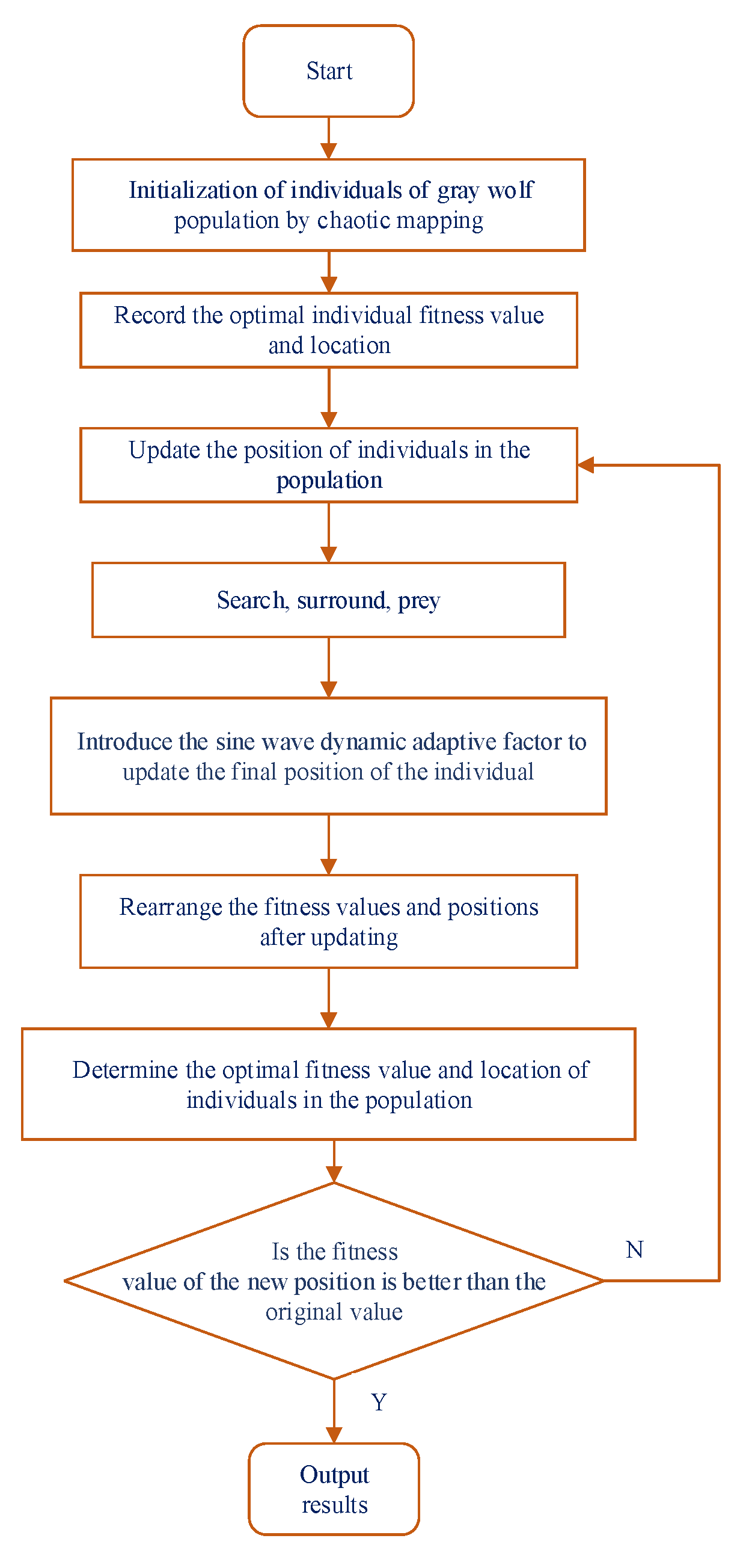
3.3. Steps of Modified Gray Wolf Optimization Algorithm

The detailed steps of the MGWO algorithm proposed in this study are as follows.
(1)
Initialize the parameters of GWO: set the population number of N; the maximum number of iterations Tmax; candidate solution dimension D, etc.
(2)
The chaotic sequences based on tent map was used to the initialization of the GWO, and the fitness value was calculated. According to the fitness value, the gray wolf population was classified into the wolf α ,   β , δ and ω .
(3)
Update parameters a, A and C of GWO.
(4)
Update the positions of each wolf and add sine wave dynamic adaptive factor into the final position update formula of each individual.
(5)
Rearrange the fitness value and the position of population after update. If the fitness value of the updated position is better, the updated position is retained. Otherwise, the new position is ignored.
(6)
Determine whether better convergence accuracy is achieved. If reached, end the search and output the position of α . Otherwise, go back to step 2.
The flow chart of MGWO is shown in Figure 1.

3.4. Algorithm Testing

In order to verify the performance of the MGWO, two groups of test functions were used to verify the performance of the algorithm. The first group is unimodal and the second group is multimodal. Each group consists of three test functions. The specific expressions of the two groups of test functions, as well as the optimal value, range and other information are shown in Table 1.
In order to fully compare the performance of each algorithm, the original GWO algorithm, particle swarm otimization (PSO) algorithm and sailfish optimization (SFO) algorithm are selected to solve the proposed six test functions. In order to prevent the experimental error caused by the contingency, each test function is run independently for 30 times, and each algorithm is evaluated with the optimal value and the average value. The experimental environment is Windows operating system, 8G memory, Intel Core i7 processor. All experiments are written and run based on MATLAB r2017a. In the test, the number of iteration time is 500 of all algorithms, and the number of populations is 30. The attack coefficients of sailfish optimization (SFO) algorithm are 4 and 0.0001, and SF percent is 0.4. The inertia weight w in PSO algorithm is 0.0729, and the acceleration factors C1 and C2 are set to 1.5 [53]. The remaining parameters are the default values. The final algorithm test results are shown in Table 2. The result of MGWO algorithm had been in bold type.
It can be seen from the statistical results in Table 2 that the optimal value and the mean value of the solution obtained by the MGWO are close to the theoretical optimal value, besides, compared with other algorithms, the solution accuracy is greatly improved. Moreover, the average value of the solution obtained by the MGWO is far less than that of other algorithms, which indicates that MGWO has strong solution stability. To sum up, the MGWO algorithm has better solution accuracy and robustness than other algorithms under the same number of experiments and indexes for finding the optimal solution of unimodal or multimodal function. It is proved that the MGWO algorithm is effective.

4. Construction of MGWO-SVM Fault Diagnosis Model

4.1. Support Vector Machine

The essence of the classification problem is to find a partition hyperplane in the feature space based on the training set and separate the sample data of different categories. The multi-dimensional feature space often brings difficulties to classification. SVM shows unique advantages in solving small sample, nonlinear and high dimensional feature Spaces. It is based on the VC dimension theory of statistical learning theory and the principle of minimum structural risk. By selecting appropriate kernel functions, linear and nonlinear classification problems can be effectively solved [54]. SVM maximizes the sample distance of both sides of the hyperplane by finding an optimal hyperplane. In order to maximize the distance between the hyperplane and the nearest sample point, an optimization problem was obtained as shown in Equation (17):
{ min 1 2 ω 2   +   C i   =   1 l ξ i s . t . y i ( ( ω · x i )   +   b ) 1 ξ i , i   =   1 , , l ξ i 0 , i   =   1 , , l
where,   C > 0 , ξ i is the relaxation variable.
The Lagrange function corresponding to the above formula is shown in the following formula:
L ( w , b , ξ , α , γ )   =   1 2 w 2 i   =   1 l α i ( y i ( ( w · x i )   +   b ) 1 + ξ i ) + C i = 1 l ξ i i = 1 l γ i ξ i
where, α i , ξ i are the Lagrange multiplier.
The dual problem obtained is shown in Equation (19):
{ max α i = 1 l α i 1 2 i , j = 1 l y i y j α i α j K ( x i , x j ) s . t . i = 1 l α i y i = 0 0 α i C , i = 1 , , l
The decision function is as follows:
f ( x ) = sign [ i , j = 1 l α i y i K ( x i , x j ) + b ]
where, Q is the number of classifiers.

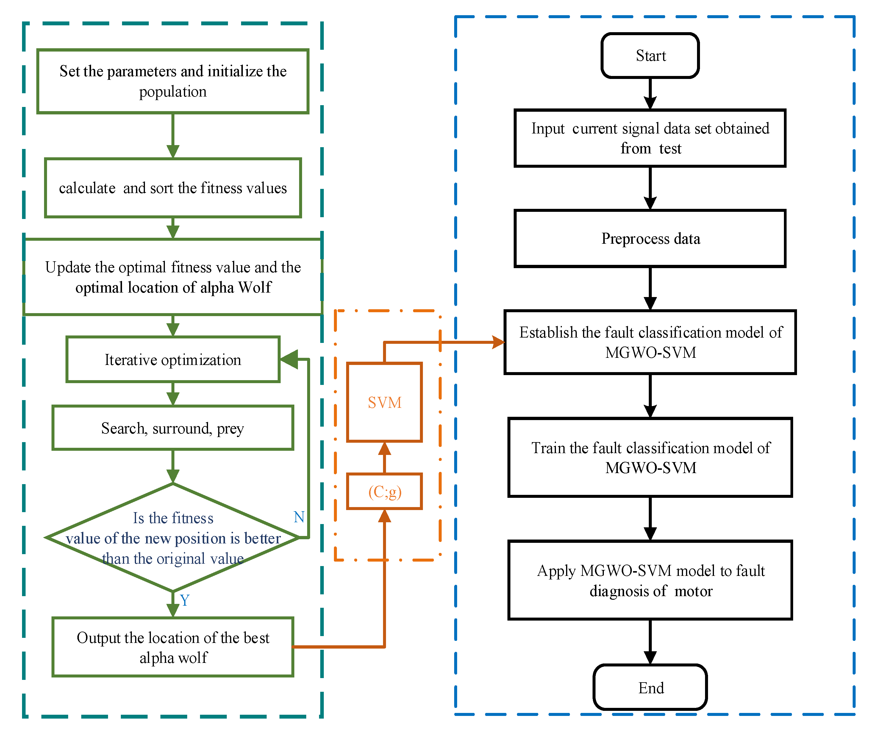
4.2. Model of MGWO-SVM

In this study, a fault diagnosis method based on MGWO-SVM model was proposed. The detailed steps of the motor fault diagnosis method based on MGWO-SVM are shown in Figure 2. The idea of this method can be described as follows.
Step1:
Test the “normal” and the other 6 fault states of motor bearing respectively, extract the current signal data of 7 states, and build the current signal data set of the input model accordingly.
Step2:
Process the current signal data set of the input model.
Step3:
Randomly confuse the data by groups, divide the training data set and the test data set, in order to prepare for better training and testing of SVM model.
Step4:
Set the gray wolf population size and iteration times, initialize the gray wolf population, and set the punishment factor C and radial basis kernel function g in SVM as the individual positions of gray Wolf, x i , j = ( C i , 1 , g i , 2 ) .
Step5:
Take the SVM classification accuracy as the fitness value of the algorithm, calculate the fitness value, and sort the population individual according to the fitness value.
Step6:
As the number of iterations of the MGWO is superposition, determine whether the optimal fitness value is reached and determine whether the maximum number of iterations is reached. If not, return step 5.
Step7:
The optimal penalty factor C and the radial basis function parameter g obtained from the optimization of the MGWO algorithm were inserted into the SVM model, based on which the fault diagnosis model of the MGWO-SVM was constructed.
Step8:
The training data set trained the MGWO-SVM model, and after the training, the model tests the remaining data set.
Step9:
Analyze the fault diagnosis results of MGWO-SVM model for motor.

5. Case Studies

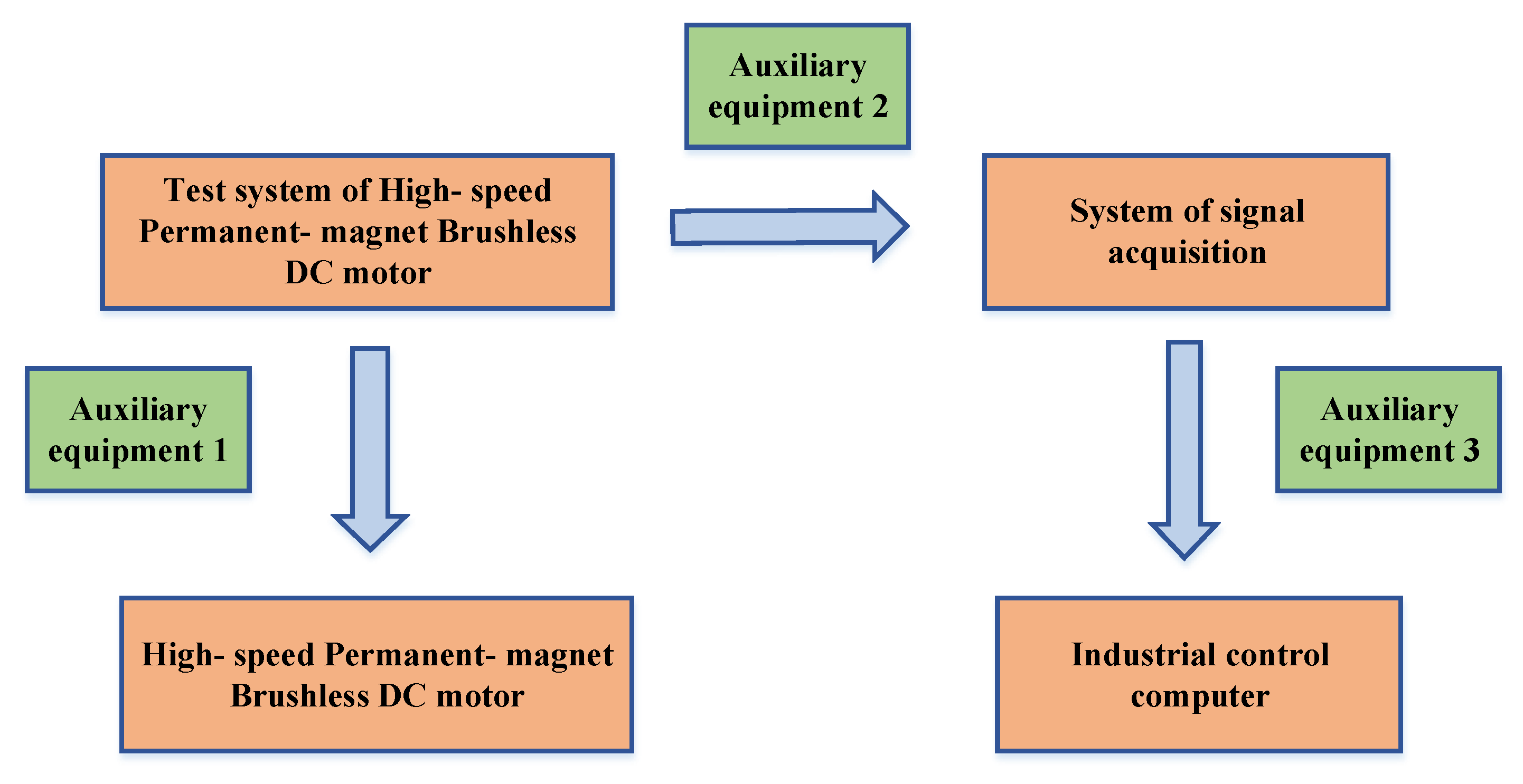
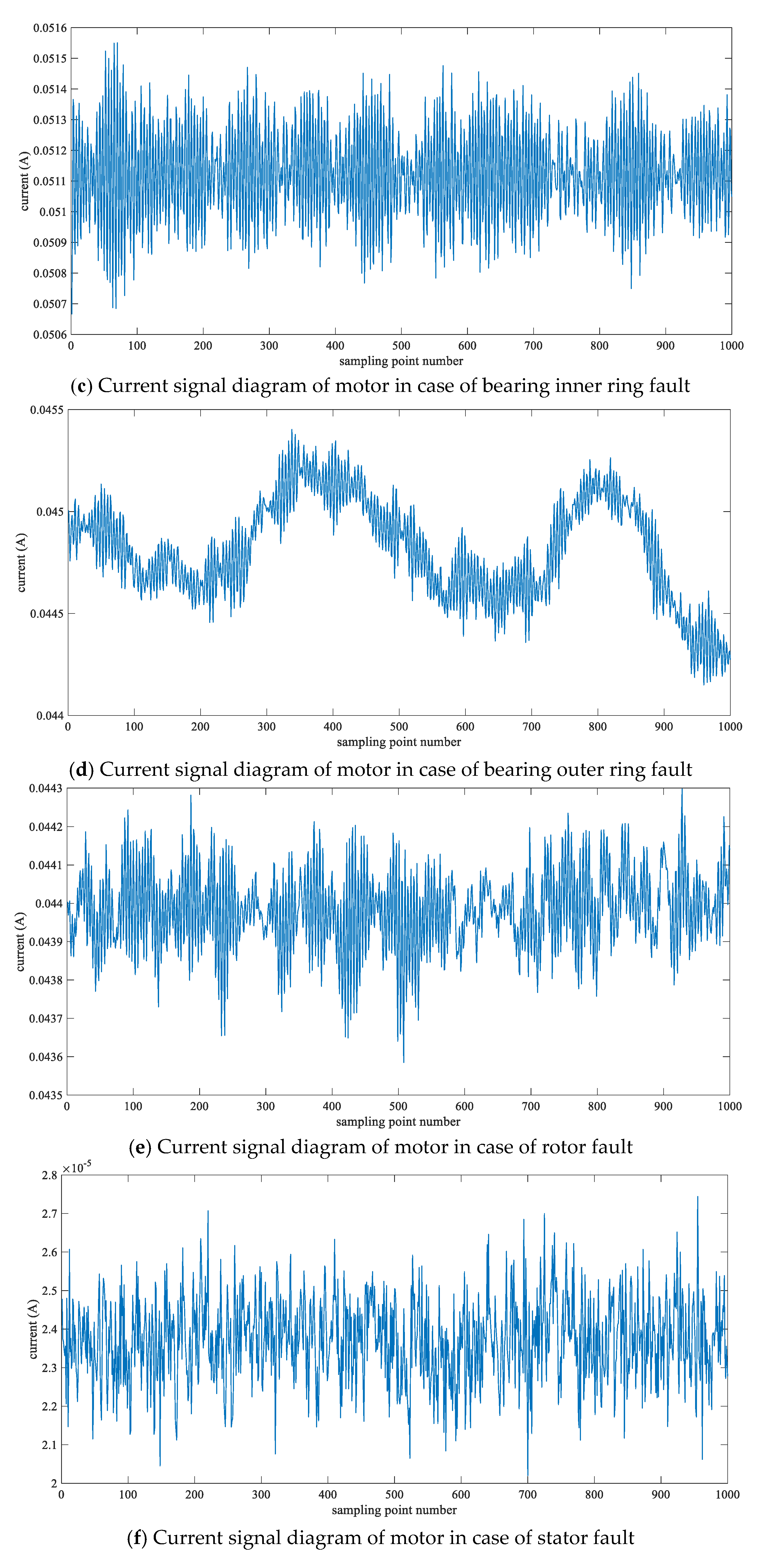
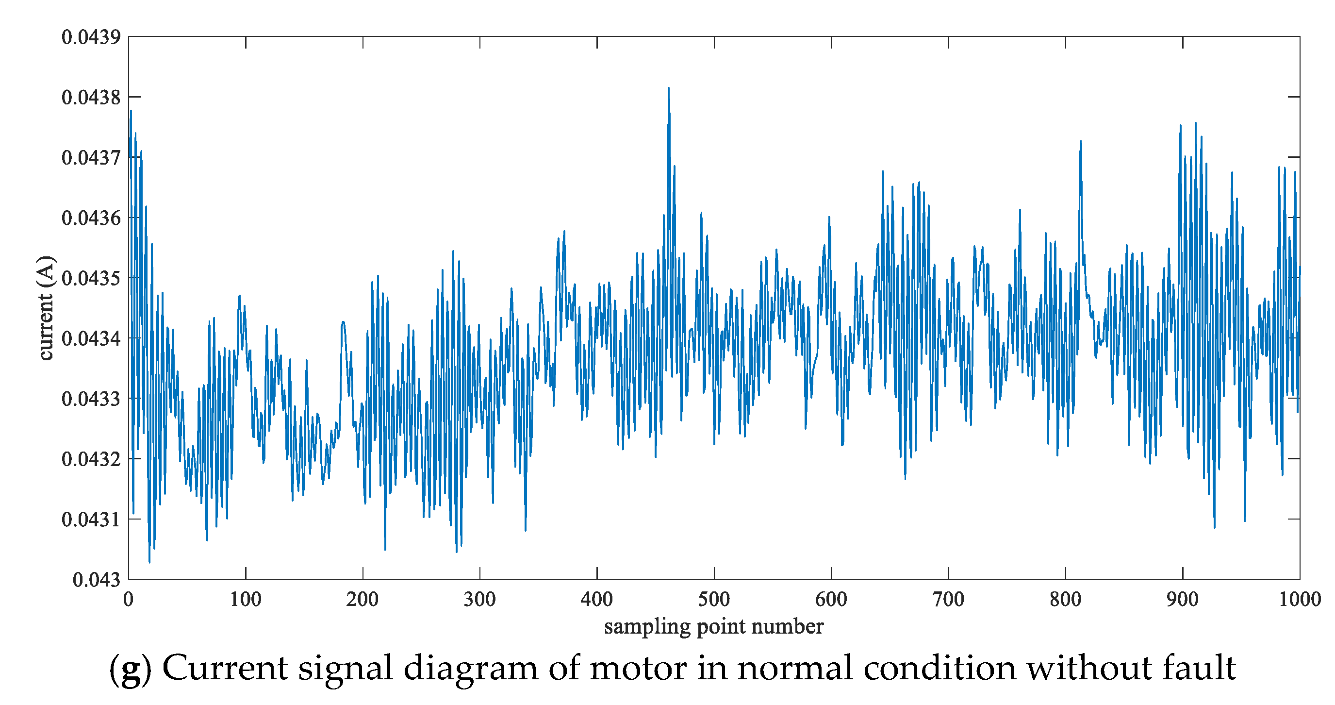
5.1. Experimental Data Extraction

In this study, a high-speed permanent-magnet brushless DC motor was selected for the experiment, the uniqueness of the variable was guaranteed, and the debugging state of the motor in each experiment was consistent, so as to avoid the interference caused by the interaction of multiple faults, so as to obtain accurate experimental data. The schematic diagram of test system of motor is shown in Figure 3.
The fault test system of motor mainly includes the following equipment: (1) high-speed permanent-magnet brushless motor; (2) industrial control computer; (3) system of signal acquisition; (4) test system of high-speed permanent-magnet brushless motor; (5) auxiliary equipment. The specific current signal data acquisition and operation steps are as follows.
Step1:
Select 2 qualified motors, 4 qualified motor bearings and fault parts required for testing different states, and clean them with filtered gasoline for standby;
Step2:
Test the qualified motor, and extract the current signal;
Step3:
Install qualified fault-free bearing on the motor with stator fault for test, and collect stator fault current signal;
Step4:
Install qualified fault-free bearing on the motor with rotor fault for test, and collect rotor fault current signal;
Step5:
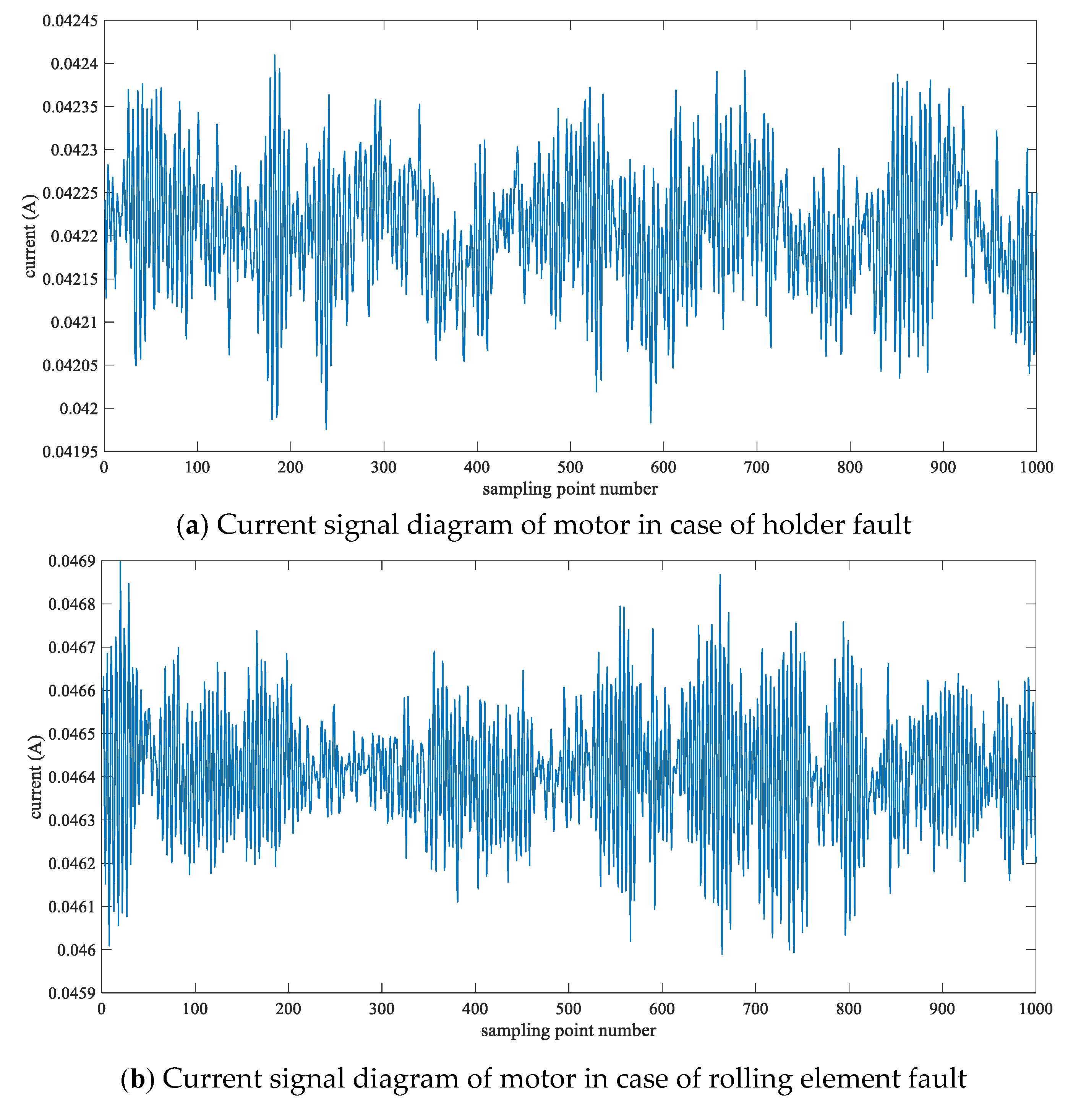
Replace the qualified bearing with a bearing with only holder fault on the qualified motor, and extract the current signal;
Step6:
Replace the qualified bearing with a bearing with only rolling element fault on the qualified motor, and extract the current signal;
Step7:
Replace the qualified bearing with a bearing with only bearing inner ring fault on the qualified motor, and extract the current signal;
Step8:
Replace the qualified bearing with a bearing with only bearing outer ring fault on the qualified motor, and extract the current signal;
Step9:
Sort out the extracted current signal, complete the current signal acquisition and test under different states of the motor.
To sum up, experiment respectively in “holder fault”, “rolling element fault”, “bearing inner ring fault”, “bearing outer ring fault”, “rotor fault”, “stator fault” and “normal” by seven different state motor current signal 40 sets of data collection, a total of 280 groups of data, each group of data is made up of 1000 sampling points. The current waveform signals of motor in normal and different fault states are collected, as shown in Figure 4. In Figure 4, the abscissa represents the sampling point number (unit: Times), and the ordinate represents the amplitude of current (unit: A).

5.2. Data Processing

First of all, as the fluctuation of input data would adversely affect the accuracy of model classification results, the original data in the scaling process can enhance the performance of test data classification and improve the classification accuracy of the model, so it is necessary to conduct normalization processing of input data. In this study, mapminmax function was used to process the data including training data and test data according to the characteristics of motor fault current signal. The principle of data processing in this paper can be explained as follows.
I scale , i = I i I min I max I min
where, I s c a l e , i is the normalized current signal of motor; I i is the true value of the status current signal of the motor; I m a x and I m i n are the maximum and minimum values of the current signal of motor.
Then, as a result of current signal data was collected in different fault conditions, in order to better verify the validity of the proposed algorithm model and the accuracy of fault diagnosis, before inputting the fault diagnosis model, the current signal data upset by groups, and made any adjacent groups of two or more current signal did not belong to the same fault condition.
In order to obtain better classification results of motor faults, classification accuracy was selected as the target of algorithm optimization in this study, which can be expressed as follows.
A c c u r a c y = N u m . r i g h t N u m . t o t a l × 100 %
where, Num.right is the correct number of model fault diagnosis; Num.total is the total number of participants in the fault diagnosis.

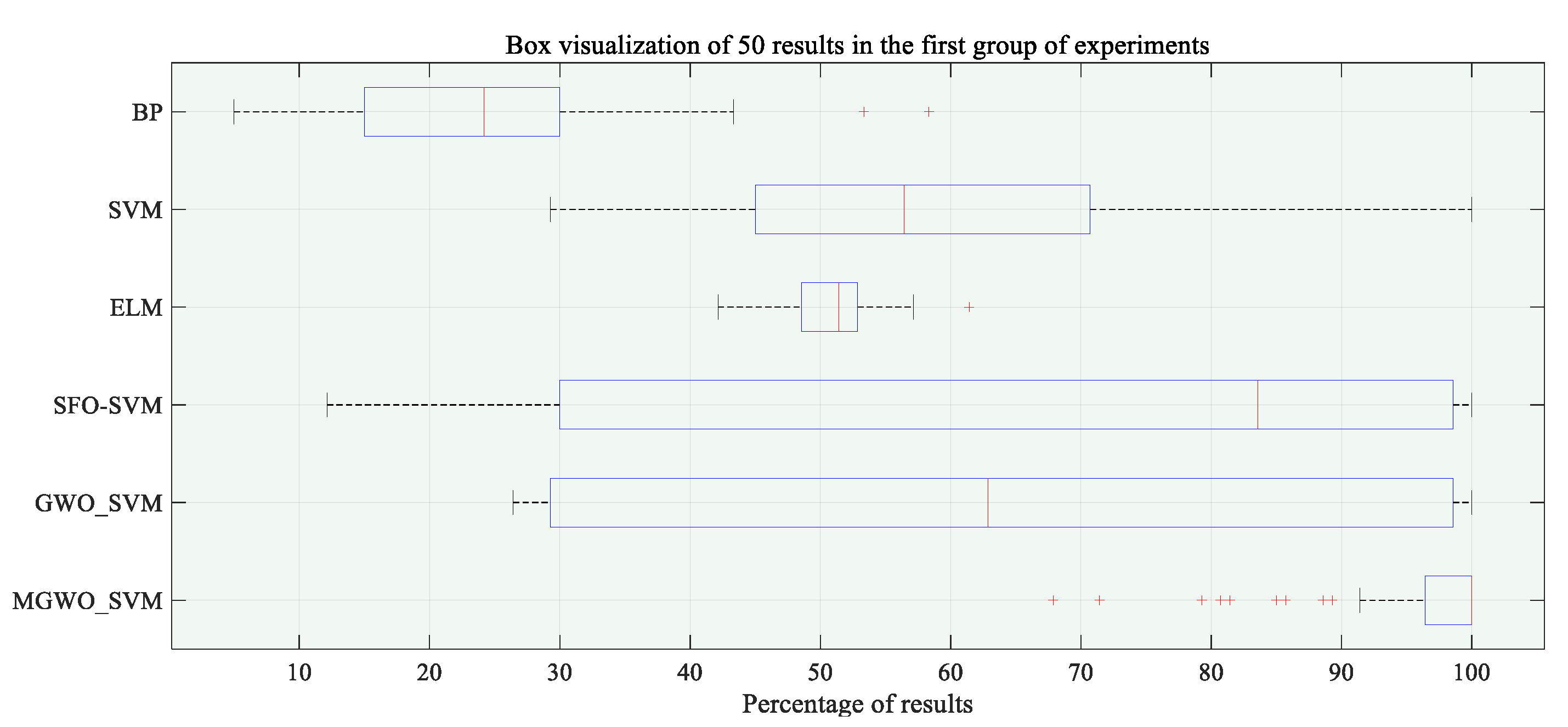
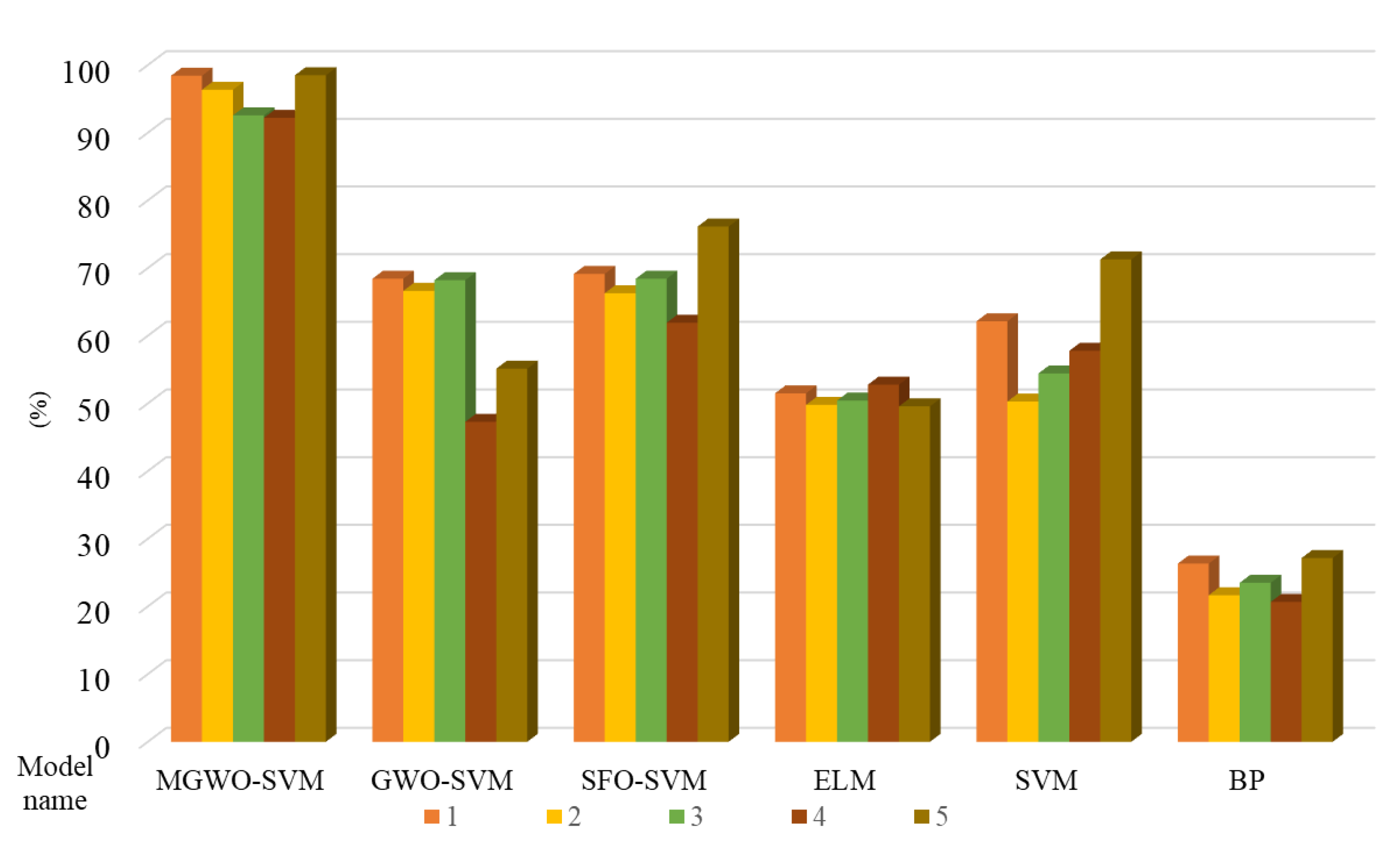
5.3. Experimental Analysis

The MGWO-SVM model proposed in this study was used for fault diagnosis. In order to better reflect the performance of the MGWO-SVM fault diagnosis model, the model proposed in this study was compared with the fault classification results of GWO-SVM, SFO-SVM, SVM, BP and ELM models. The parameter settings of the algorithm were shown in Table 3. The parameters not mentioned were default values. Among them, SFO is a new intelligent algorithm appearing in 2019. In this study, it was used to optimized SVM and construct the SFO-SVM classification model as a comparison model. In addition, to avoid the contingency of experimental results, in this study, the experimental environment of each model was Windows operating system, 8G memory and IntelCorei7 processor. All experiments were written and run based on Matlab R2017a.
Firstly, the collected current signals of the motor in different states were selected to carry out the first group of 50 fault diagnosis experiments. The training and testing parts of each experiment are 50% of the whole. The first 50% of the current signals collected and processed by the test were trained by the fault diagnosis model, and then the remaining 50% were tested. Each model was repeated 50 times. The results of any ten consecutive fault diagnoses in the first group of experiments were summarized in Table 4.
In order to prove the effectiveness of the model proposed in this study for motor fault diagnosis, the experimental results were compared with MGWO-SVM, SFO-SVM, SVM, ELM and BP classification models. Table 4 showed the results and average values of 10 consecutive experiments taken randomly in the first group of 50 experiments. By comparing the fault diagnosis accuracy of each model in Table 4, it can be seen that the fault diagnosis accuracy of the model proposed in this study is the highest. Compared with the GWO-SVM model, the accuracy of this model is improved by 30%. Compared with the SVM classification model, the classification accuracy of MGWO-SVM model is improved by 36.287%. So as to better view the experimental results, this study analyzed and collated the experimental results. Box visualization of the detailed results of the first group of experiments is shown in Figure 5. In the first group of 50 fault diagnosis experiments, the comparison figure of fault diagnosis accuracy of different models with 10 experiments as a part was shown in Figure 6.
Figure 5 showed the results of the six models for the motor fault diagnosis. It can be seen that the fault classification of motor by the MGWO-SVM model proposed in this study is closer to the real fault state classification, and there is no abnormal point with too large classification deviation. As can be seen from Figure 6, the proposed model has high fault diagnosis accuracy and good robust performance, so it had obvious advantages to study the fault diagnosis of motor. In addition, it can be concluded from Figure 5 and Figure 6 that the effect of SVM in fault diagnosis research in this study is better than that of ELM and BP. The bar chart of fault diagnosis accuracy in the test set was shown in Figure 7. In Figure 7, the dark part and the light part represent the fault diagnosis experiments with high and low classification accuracy respectively. From the distribution of color depth, it could be seen that the accuracy of the classification results of the proposed model is not less than 60%. Through the statistics and analysis of the results, it could be seen that the classification accuracy of the model proposed in this study is the best after comparing the six models. Compared with the other five classification models, the classification accuracy of the model was significantly improved, which also proved the good effect of the proposed model for motor fault diagnosis.
In order to prove the effectiveness and accuracy of the MGWO-SVM model proposed in the study of motor fault diagnosis, the second group of experimental tests were carried out on the basis of the above experiments, and the results of different algorithm models were compared respectively. The same as the first group of experiment, the training part and the test part are both 50% of the whole. The first 50% of the current signals after data processing were trained through the model, and then the remaining 50% were tested for fault diagnosis. Each model was repeated 50 times. The results of ten consecutive fault diagnosis experiments in the second group were shown in Table 5.
Table 5 recorded the fault diagnosis results taken randomly for 10 consecutive times in the second group of experiments, among which the training samples and test samples are consistent with those in the first group of experiments. It could be seen from the table that, among the above six classification models, the MGWO-SVM model proposed in this study had the highest fault diagnosis accuracy. The fault diagnosis accuracy rate of the proposed model is 27.643% and 30.195% higher than that of GWO-SVM and SFO-SVM models, which is superior to the classification accuracy of the classical SVM model of 32.357%. Through the comparison of the above models in the study of motor fault diagnosis, it can be clearly seen that the classification model constructed by the MGWO and SVM has a high accuracy rate. The experimental results showed that the MGWO had better optimization capability and convergence precision than the traditional algorithm, which made the MGWO-SVM model have higher fault diagnosis accuracy and good robustness, and proved the effectiveness of the GWO algorithm improvement.
Figure 8 and Figure 9 showed the classification result diagram and classification accuracy comparison diagram of each model in the second group of 50 experiments. In addition, compared with ELM and BP classification models, SVM has a higher classification ability, which further proves its advantages in solving nonlinear classification problems. This is also the reason why SVM is chosen in this study. Combining SVM with the MGWO algorithm with excellent optimization performance and convergence performance, kernel function parameters and penalty factors were found to make the SVM model achieve the best classification effect, so as to achieve high accuracy of fault diagnosis experimental results.
Figure 10 showed the bar chart of the fault diagnosis accuracy of the test set in the second group of experiments. It could be seen from the graph that the classification accuracy results of the MGWO-SVM model are mostly above 90%, among which 65.79% can achieve completely correct classification. In general, the classification accuracy of GWO-SVM and SFO-SVM models was improved by 33.715% and 34.115% respectively. In addition, the average accuracy result of SVM classification model is higher than that of ELM, BP classification model, 8.772% and 30.462%. To sum up, in the fault diagnosis experiment of motor, the classification capability of the MGWO-SVM model proposed in this study is superior to other classification models. Therefore, the method proposed in this study is more suitable for the fault diagnosis of motor.
The fault diagnosis model proposed in this study could be used for the fault diagnosis of motor, which could realize the fault state identification with high accuracy. The maintainer and related staff would make timely adjustments, replacing the corresponding fault unit, reducing economic losses and casualties thereby providing a safe, stable and reliable system working environment.

6. Conclusions

The high-speed permanent-magnet brushless DC motor is used in many fields. It is of great significance to study its fault diagnosis and reliability to maintain the reliability of its working system. The study on the fault diagnosis of the motor could determine the fault components which went out of order, then deal with or replace it in time, in order to make the motor reach a better working state, whose reliability of the working system can be better developed and the direction of the “advanced-precise-top” would be reached. The MGWO-SVM fault diagnosis model proposed in this study has excellent performance in the current signal data classification experiment of motor collected in different states. Through two groups of experiments, the fault diagnosis accuracy rate of the proposed model is higher than that of the other models, and the mean difference of experimental results is almost less than 5%, which also proves that the model has good fault diagnosis performance. In the actual working condition, the maintainer would judge the state of the motor according to the current signal input fault diagnosis model what was proposed in this study, and the different fault part for maintenance or replacement. The fault diagnosis model with high accuracy could provide more accurate reference for the fault diagnosis research of the motor and the reliability research plan of its working system, so as to improve the accuracy of the whole system.
Specifically, the main contributions of this study includes the following three aspects: (1) Given the limitations of the GWO algorithm in the optimization process, this study proposed chaotic map and sine wave dynamic adaptive factor of combining the MGWO algorithm, based on the unimodal and multimodal test of two groups of classical test functions, proved that both MGWO convergence and robustness of the algorithm are better than other intelligent algorithms, such as PSO and SFO. (2) A current data signal collection test of the motor in different states was proposed. Based on the variable uniqueness, current data signals of normal and six fault states of the motor were collected for the experimental study of motor fault diagnosis. (3) A new motor fault diagnosis method based on MGWO-SVM was proposed. The fault diagnosis accuracy is improved by combining the MGWO with the SVM model. The fault diagnosis rate of the proposed model is obviously better than that of other models by testing the current signals in different states collected in the previous step. Therefore, in this study, current signal data sets of the motor in different states were obtained through current signal acquisition tests of the motor in different states, and the proposed MGWO-SVM model was used to study the fault diagnosis of the motor, proving that the proposed model has better diagnostic accuracy and robustness. The fault diagnosis model proposed in this paper could also be applied to the fault diagnosis research of more objects, such as the fault diagnosis research of DC generator in reference [55] and the fault diagnosis research of three-phase asynchronous motor in reference [56].
The study also has some limitations. Since the proposed model was based on SVM, the classification results depend on the classification ability of SVM. When processing a larger data sample, a large amount of data would lead to a decrease in its testing efficiency, and the extent of decline is impossible to estimate. In addition, the experimental results have proved the good classification ability of the MGWO-SVM model, but the general scope of the model has limitations. Therefore, it should be used for more classification experiments of different states or other motor fault diagnosis experimental research.
In the future, more models should be introduced, such as the least squares support vector machine model, mixtures of gaussian processes models, etc., to provide more model choices for the fault diagnosis field. As for the reliability research of high-speed permanent-magnet brushless DC motor, the model proposed in this study is suitable for the fault diagnosis research. The reliability research of other aspects the motor is limited, so more aspects (such as the life prediction) need to be expanded to comprehensively study the reliability of the high-speed permanent-magnet brushless DC motor. In addition, different combination methods based on models and mixed classification methods based on different models should be studied, and more advanced methods should be adopted to improve the accuracy of the classification, so as to improve the fault diagnosis accuracy of motor.

Author Contributions

Conceptualization, L.-L.L. and J.-Q.L.; methodology, L.-L.L. and J.-Q.L.; software, L.-L.L. and J.-Q.L.; formal analysis, L.-L.L. and W.-B.Z.; data curation, L.-L.L., J.-Q.L. and L.D.; writing—original draft preparation, L.-L.L., J.-Q.L., W.-B.Z. and L.D.; writing—review and editing, W.-B.Z. and L.D. All authors have read and agreed to the published version of the manuscript.

Funding

This research was funded by the Natural Science Foundation of Hebei Province of China [Project No. E2018202282].

Institutional Review Board Statement

Not applicable.

Informed Consent Statement

Not applicable.

Data Availability Statement

Not applicable.

Conflicts of Interest

The authors declare no conflict of interest.

References

  1. Dong, L.; Li, W.-M.; Wang, C.-H.; Lin, K.-P. Gyro motor fault classification model based on a coupled hidden Markov model with a minimum intra-class distance algorithm. Proc. Inst. Mech. Eng. Part I J. Syst. Control Eng. 2020, 234, 646–661. [Google Scholar] [CrossRef]
  2. Zhao, R.J.; Xie, X.L.; Yu, W.Z. Repair equipment allocation problem for a support-and-repair ship on a deep sea: A hybrid multi-criteria decision making and optimization approach. Expert Syst. Appl. 2020, 160, 113658. [Google Scholar] [CrossRef]
  3. Zhou, A.M.; Yu, D.J.; Zhang, W.Y. A research on intelligent fault diagnosis of wind turbines based on ontology and FMECA. Adv. Eng. Inform. 2015, 29, 115–125. [Google Scholar] [CrossRef]
  4. Lu, C.; Wang, Z.-Y.; Qin, W.-L.; Ma, J. Fault diagnosis of rotary machinery components using a stacked denoising autoencoder-based health state identification. Signal Process. 2017, 130, 377–388. [Google Scholar] [CrossRef]
  5. Liu, H.; Zhou, J.; Zheng, Y.; Jiang, W.; Zhang, Y. Fault diagnosis of rolling bearings with recurrent neural network-based autoencoders. ISA Trans. 2018, 77, 167–178. [Google Scholar] [CrossRef] [PubMed]
  6. Zhu, Z.; Peng, G.; Chen, Y.; Peng, G. A convolutional neural network based on a capsule network with strong generalization for bearing fault diagnosis. Neurocomputing 2019, 323, 62–75. [Google Scholar] [CrossRef]
  7. Gangsar, P.; Tiwari, R. A support vector machine based fault diagnostics of Induction motors for practical situation of multi-sensor limited data case. Measurement 2019, 135, 694–711. [Google Scholar] [CrossRef]
  8. Saucedo-Dorantes, J.J.; Prieto, M.D.; Ortega, J.A.; Osornio-Rios, R.A.; Romero-Troncoso, R.D.J. Multiple-Fault Detection Methodology Based on Vibration and Current Analysis Applied to Bearings in Induction Motors and Gearboxes on the Kinematic Chain. Shock. Vib. 2016, 2016, 5467643. [Google Scholar] [CrossRef]
  9. Chen, H.; Sun, H.; Junejo, N.U.R.; Yang, G.; Qi, J. Whale Vocalization Classification Using Feature Extraction With Resonance Sparse Signal Decomposition and Ridge Extraction. IEEE Access 2019, 7, 136358–136368. [Google Scholar] [CrossRef]
  10. Zhou, Y.; Lin, L.; Wang, D.; He, M.; He, D. A new method to classify railway vehicle axle fatigue crack AE signal. Appl. Acoust. 2018, 131, 174–185. [Google Scholar] [CrossRef]
  11. Stetco, A.; Dinmohammadi, F.; Zhao, X.; Robu, V.; Flynn, D.; Barnes, M.; Keane, J.; Nenadic, G. Machine learning methods for wind turbine condition monitoring: A review. Renew. Energy 2019, 133, 620–635. [Google Scholar] [CrossRef]
  12. Ali, M.Z.; Shabbir, N.S.K.; Liang, X.; Zhang, Y.; Hu, T. Machine Learning-Based Fault Diagnosis for Single- and Multi-Faults in Induction Motors Using Measured Stator Currents and Vibration Signals. IEEE Trans. Ind. Appl. 2019, 55, 2378–2391. [Google Scholar] [CrossRef]
  13. Zhang, J.; Zhang, J.; Zhong, M.; Zheng, J.; Yao, L. A GOA-MSVM based strategy to achieve high fault identification accuracy for rotating machinery under different load conditions. Measurement 2020, 163, 108067. [Google Scholar] [CrossRef]
  14. Zhao, H.; Gao, Y.; Liu, H.; Li, L. Fault diagnosis of wind turbine bearing based on stochastic subspace identification and multi-kernel support vector machine. J. Mod. Power Syst. Clean Energy 2019, 7, 350–356. [Google Scholar] [CrossRef] [Green Version]
  15. Keskes, H.; Braham, A. Recursive Undecimated Wavelet Packet Transform and DAG SVM for Induction Motor Diagnosis. IEEE Trans. Ind. Inform. 2015, 11, 1059–1066. [Google Scholar] [CrossRef]
  16. Qiu, G.; Huang, S.; Gu, Y. Experimental investigation and multi-conditions identification method of centrifugal pump using Fisher discriminant ratio and support vector machine. Adv. Mech. Eng. 2019, 11, 1687814019878041. [Google Scholar] [CrossRef]
  17. Zeng, B.; Guo, J.; Zhu, W.; Xiao, Z.; Yuan, F.; Huang, S. A Transformer Fault Diagnosis Model Based On Hybrid Grey Wolf Optimizer and LS-SVM. Energies 2019, 12, 4170. [Google Scholar] [CrossRef] [Green Version]
  18. Huang, X.; Huang, X.; Wang, B.; Xie, Z. Fault diagnosis of transformer based on modified grey wolf optimization algorithm and support vector machine. IEEJ Trans. Electr. Electron. Eng. 2020, 15, 409–417. [Google Scholar] [CrossRef]
  19. Yu, J.; Zhang, C.; Wang, S. Multichannel one-dimensional convolutional neural network-based feature learning for fault diagnosis of industrial processes. Neural Comput. Appl. 2020. [Google Scholar] [CrossRef]
  20. Zhao, Y.; Li, T.; Zhang, X.; Zhang, C. Artificial intelligence-based fault detection and diagnosis methods for building energy systems: Advantages, challenges and the future. Renew. Sustain. Energy Rev. 2019, 109, 85–101. [Google Scholar] [CrossRef]
  21. Shao, S.; Wheeler, P.W.; Clare, J.C.; Watson, A.J. Fault Detection for Modular Multilevel Converters Based on Sliding Mode Observer. IEEE Trans. Power Electron. 2013, 28, 4867–4872. [Google Scholar] [CrossRef] [Green Version]
  22. Wan, X.-J.; Liu, L.; Xu, Z.; Xu, Z.; Li, Q.; Xu, F. Fault diagnosis of rolling bearing based on optimized soft competitive learning Fuzzy ART and similarity evaluation technique. Adv. Eng. Inform. 2018, 38, 91–100. [Google Scholar] [CrossRef]
  23. Bellini, A.; Filippetti, F.; Tassoni, C.; Capolino, G.-A. Advances in Diagnostic Techniques for Induction Machines. IEEE Trans. Ind. Electron. 2008, 55, 4109–4126. [Google Scholar] [CrossRef]
  24. Wu, X.; Tian, R.; Cheng, S.; Chen, T.; Tong, L. A Nonintrusive Diagnostic Method for Open-Circuit Faults of Locomotive Inverters Based on Output Current Trajectory. IEEE Trans. Power Electron. 2017, 33, 4328–4341. [Google Scholar] [CrossRef]
  25. Ben Youssef, A.; El Khil, S.K.; Slama-Belkhodja, I. State Observer-Based Sensor Fault Detection and Isolation, and Fault Tolerant Control of a Single-Phase PWM Rectifier for Electric Railway Traction. IEEE Trans. Power Electron. 2013, 28, 5842–5853. [Google Scholar] [CrossRef]
  26. Huang, Z.J.; Wang, Z.S.A. Multiswitch Open-Circuit Fault Diagnosis of Microgrid Inverter Based on Slidable Triangu-larization Processing. IEEE Trans. Power Electron. 2021, 36, 922–930. [Google Scholar] [CrossRef]
  27. Kumar, A.; Shankar, R.; Thakur, L.S. A big data driven sustainable manufacturing framework for condition-based maintenance prediction. J. Comput. Sci. 2018, 27, 428–439. [Google Scholar] [CrossRef]
  28. Wu, X.; Ye, Q. Fault diagnosis and prognostic of solid oxide fuel cells. J. Power Sources 2016, 321, 47–56. [Google Scholar] [CrossRef]
  29. An, H.; Liang, W.; Zhang, Y.; Tan, J. Hidden Markov model based rotate vector reducer fault detection using acoustic emissions. Int. J. Sens. Netw. 2020, 32, 116–125. [Google Scholar] [CrossRef]
  30. Duan, L.; Hu, J.; Zhao, G.; Chen, K.; Wang, S.X.; He, J. Method of inter-turn fault detection for next-generation smart transformers based on deep learning algorithm. High Volt. 2019, 4, 282–291. [Google Scholar] [CrossRef]
  31. Chen, X.; Zhang, B.; Gao, D. Bearing fault diagnosis base on multi-scale CNN and LSTM model. J. Intell. Manuf. 2020. [Google Scholar] [CrossRef]
  32. Cho, K.-H.; Jo, H.-C.; Kim, E.-S.; Park, H.-A.; Park, J.H. Failure Diagnosis Method of Photovoltaic Generator Using Support Vector Machine. J. Electr. Eng. Technol. 2020, 15, 1669–1680. [Google Scholar] [CrossRef]
  33. Guedes, A.S.; Silva, S.M.; Filho, B.D.J.C.; Conceição, C.A. Evaluation of electrical insulation in three-phase induction motors and classification of failures using neural networks. Electr. Power Syst. Res. 2016, 140, 263–273. [Google Scholar] [CrossRef]
  34. Zhou, L.; Lin, T.; Zhou, X.; Gao, S.; Wu, Z.; Zhang, C. Detection of Winding Faults Using Image Features and Binary Tree Support Vector Machine for Autotransformer. IEEE Trans. Transp. Electrif. 2020, 6, 625–634. [Google Scholar] [CrossRef]
  35. Neffati, S.; Ben Abdellafou, K.; Taouali, O.; Bouzrara, K. Enhanced SVM–KPCA Method for Brain MR Image Classification. Comput. J. 2019, 63, 383–394. [Google Scholar] [CrossRef]
  36. Ge, J.; Niu, T.; Xu, D.; Yin, G.; Wang, Y. A Rolling Bearing Fault Diagnosis Method Based on EEMD-WSST Signal Reconstruction and Multi-Scale En-tropy. Entropy 2020, 22, 290. [Google Scholar] [CrossRef] [Green Version]
  37. Ren, H.; Liu, W.; Shan, M.; Wang, X. A new wind turbine health condition monitoring method based on VMD-MPE and feature-based transfer learning. Measurement 2019, 148, 106906. [Google Scholar] [CrossRef]
  38. Bazan, G.H.; Scalassara, P.R.; Endo, W.; Goedtel, A. Information Theoretical Measurements From Induction Motors Under Several Load and Voltage Conditions for Bearing Faults Classification. IEEE Trans. Ind. Inform. 2019, 16, 3640–3650. [Google Scholar] [CrossRef]
  39. Chen, P.; Zhao, X.; Zhu, Q. A novel classification method based on ICGOA-KELM for fault diagnosis of rolling bearing. Appl. Intell. 2020, 50, 2833–2847. [Google Scholar] [CrossRef]
  40. Zhang, J.; Sun, H.; Sun, Z.; Dong, Y.; Dong, W. Open-Circuit Fault Diagnosis of Wind Power Converter Using Variational Mode Decomposition, Trend Feature Analysis and Deep Belief Network. Appl. Sci. 2020, 10, 2146. [Google Scholar] [CrossRef] [Green Version]
  41. Wu, J.; Guo, P.; Cheng, Y.; Zhu, H.; Wang, X.B.; Shao, X. Ensemble generalized multiclass support-vector-machine-based health evaluation of complex degradation systems. IEEE/ASME Trans. Mechatron. 2020, 25, 2230–2240. [Google Scholar] [CrossRef]
  42. Huachun, W.; Jian, Z.; Chunhu, X.; Jiyang, Z.; Yiming, H. Two-dimensional time series sample entropy algorithm: Applications to rotor axis orbit feature identification. Mech. Syst. Signal Process. 2021, 147, 107123. [Google Scholar] [CrossRef]
  43. Yuan, X.; Liu, Z.; Miao, Z.; Zhao, Z.; Zhou, F.; Song, Y. Fault Diagnosis of Analog Circuits Based on IH-PSO Optimized Support Vector Machine. IEEE Access 2019, 7, 137945–137958. [Google Scholar] [CrossRef]
  44. Zhou, Z.; Li, G.; Wang, J.; Chen, H.; Zhong, H.; Cao, Z. A comparison study of basic data-driven fault diagnosis methods for variable refrigerant flow system. Energy Build. 2020, 224, 110232. [Google Scholar] [CrossRef]
  45. Qin, A.; Hu, Q.; Zhang, Q.; Lv, Y.; Sun, G. Application of sensitive dimensionless parameters and PSO–SVM for fault classification in rotating machinery. Assem. Autom. 2019, 40, 175–187. [Google Scholar] [CrossRef]
  46. Hu, H.; Tian, S.; Guo, Q.; Ouyang, A. The Application of HIWO–SVM in Analog Circuit Fault Diagnosis. Int. J. Pattern Recognit. Artif. Intell. 2015, 29, 1550019. [Google Scholar] [CrossRef]
  47. Guo, K.; Cui, L.; Mao, M.; Zhou, L.; Zhang, Q. An Improved Gray Wolf Optimizer MPPT Algorithm for PV System With BFBIC Converter Under Partial Shading. IEEE Access 2020, 8, 103476–103490. [Google Scholar] [CrossRef]
  48. Gölcük, I.; Ozsoydan, F.B. Evolutionary and adaptive inheritance enhanced Grey Wolf Optimization algorithm for binary domains. Knowledge-Based Syst. 2020, 194, 105586. [Google Scholar] [CrossRef]
  49. Heidari, A.A.; Pahlavani, P. An efficient modified grey wolf optimizer with Lévy flight for optimization tasks. Appl. Soft Comput. 2017, 60, 115–134. [Google Scholar] [CrossRef]
  50. Mirjalili, S.; Mirjalili, S.M.; Lewis, A. Grey wolf optimizer. Adv. Eng. Softw. 2014, 69, 46–61. [Google Scholar] [CrossRef] [Green Version]
  51. Cui, Y. Application of the Improved Chaotic Self-Adapting Monkey Algorithm into Radar Systems of Internet of Things. IEEE Access 2018, 6, 54270–54281. [Google Scholar] [CrossRef]
  52. Singh, N.J.; Dhillon, J.; Kothari, D. Non-interactive approach to solve multi-objective thermal power dispatch problem using composite search algorithm. Appl. Soft Comput. 2018, 65, 644–658. [Google Scholar] [CrossRef]
  53. Li, L.-L.; Wen, S.-Y.; Tseng, M.-L.; Wang, C.-S. Renewable energy prediction: A novel short-term prediction model of photovoltaic output power. J. Clean. Prod. 2019, 228, 359–375. [Google Scholar] [CrossRef]
  54. Li, Z.; Outbib, R.; Giurgea, S.; Hissel, D.; Jemei, S.; Giraud, A.; Rosini, S. Online implementation of SVM based fault diagnosis strategy for PEMFC systems. Appl. Energy 2016, 164, 284–293. [Google Scholar] [CrossRef]
  55. Glowacz, A.; Glowacz, W.; Glowacz, Z. Recognition of armature current of DC generator depending on rotor speed using FFT, MSAF-1 and LDA. Ekspolatacja Niezawodn. Maint. Reliab. 2015, 17, 64–69. [Google Scholar] [CrossRef]
  56. Glowacz, A.; Kozik, J.; Gutten, M.; Korenciak, D.; Khan, Z.F.; Irfan, M.; Carletti, E. Fault Diagnosis of Three Phase Induction Motor Using Current Signal, MSAF-Ratio15 and Selected Classifiers. Arch. Met. Mater. 2017, 62, 2413–2419. [Google Scholar] [CrossRef]
Figure 1. The flow chart of the modified gray wolf optimization (MGWO) algorithm.
Symmetry 13 00163 g001
Figure 2. Flow chart of motor fault diagnosis based on MGWO-SVM model.
Symmetry 13 00163 g002
Figure 3. Schematic diagram of test system of motor.
Symmetry 13 00163 g003
Figure 4. Current waveform signal diagram of motor in normal and different fault states.
Symmetry 13 00163 g004aSymmetry 13 00163 g004bSymmetry 13 00163 g004c
Figure 5. Box visualization of the results of 50 experiments in the first group of experiments.
Symmetry 13 00163 g005
Figure 6. Comparison diagram of fault diagnosis accuracy of different models of 50 fault diagnosis experiments in the first group of experiments.
Symmetry 13 00163 g006
Figure 7. The bar chart of fault diagnosis accuracy of test set in the first group of experiments.
Symmetry 13 00163 g007
Figure 8. Box visualization of the results of 50 experiments in the second group of experiments.
Symmetry 13 00163 g008
Figure 9. Comparison diagram of fault diagnosis accuracy of different models of 50 fault diagnosis experiments in the second group of experiments.
Symmetry 13 00163 g009
Figure 10. The bar chart of fault diagnosis accuracy of test set in the second group of experiments.
Symmetry 13 00163 g010
Table 1. Test function information table.
FunctionLowerUpperGlobal MinimumFunction Type
f 1 = i = 1 n x i 2 −1001000Unimodal
f 2 = i = 1 n | x i | + i = 1 n | x i | −10100Unimodal
f 3 = i = 1 n ( j = 1 i x j ) 2 −1001000Unimodal
f 4 = i = 1 D i x i 4 + r a n d o m [ 0 , 1 ) −1001000Multimodal
f 5 = i = 1 n [ x i 2 10 cos ( 2 π x i ) + 10 ] −5.125.120Multimodal
f 6 = 20 exp ( 0.2 ( i = 1 n x i 2 ) / n ) exp ( 1 n i = 1 n cos ( 2 π x i ) ) + 20 + e −32320Multimodal
Table 2. Test results.
FunctionMGWOGWOSFOPSO
OptimumAverageOptimumAverageOptimumAverageOptimumAverage
F1002..00 × 10−292.19 × 10−272.58 × 10−123.63 × 10−101.48 × 10−53.44 × 10−4
F2002.19 × 10−179.47 × 10−174.28 × 10−68.74 × 10−51.44 × 10−24.13 × 10−2
F3003.05 × 10−94.72 × 10−61.22 × 10−125.31 × 10−844.80103
F41.87 × 10−61.07 × 10−43.55 × 10−42.32 × 10−38.75 × 10−57.00 × 10−43.90 × 10−29.47 × 10⁻²
F5005.68 × 10−141.89 × 10−131.73 × 10−72.10 × 10−529.6055.50
F68.88 × 10−168.88 × 10−167.55 × 10−141.08 × 10−131.34 × 10−71.23 × 10−51.59 × 10−31.63 × 10−2
Table 3. Parameter settings in the algorithm.
SVM
Parameters
Maximum IterationsPopulation NumberDimensionParameter Range of Penalty FactorParameter Range of Kernel Function
100502[0.1, 1200][0.001, 100]
SFO-SVMSF percentAttack coefficientAttack coefficient
0.440.0001
ELMNumber of neurons in hidden layer
250
BPMaximum convergence timesRate of learningConvergen-ce objective
1000.010
Table 4. Results of ten consecutive fault diagnoses in the first group of experiments.
ModelAccuracy of Different Optimization Number (%)Average
12345678910
MGWO-SVM88.57100.098.57100.0100.0100.0100.0100.099.2997.8698.430
GWO-SVM32.1497.8656.4328.57100.072.8675.0094.2998.5728.5768.430
SFO-SVM90.0097.1429.2998.5726.4284.2952.8683.5734.2995.0069.143
SVM72.1443.5770.0057.8654.29100.057.1469.2941.4355.7162.143
ELM54.2950.0047.1453.5751.4352.1452.8651.4350.7145.7150.928
BP33.3330.0010.0016.6726.6716.6758.3310.0033.3328.3326.333
Table 5. Results of ten consecutive fault diagnosis in the second group of experiments.
ModelAccuracy of Different Optimization Number (%)Average
12345678910
MGWO-SVM100.095.00100.099.29100.0100.0100.071.43100.099.2996.500
GWO-SVM99.2928.57100.027.8674.2985.0070.00100.020.0083.5768.857
SFO-SVM100.027.1426.4310027.1460.0075.7187.1477.8671.4365.285
SVM91.4357.8672.1484.2959.2961.4330.7155.7171.4357.1464.143
ELM52.1454.2956.4360.0055.7150.0050.7152.8650.0054.2953.643
BP20.0015.0033.3333.333.3313.3328.3331.6738.3310.0022.665
Publisher’s Note: MDPI stays neutral with regard to jurisdictional claims in published maps and institutional affiliations.

