Densification of Biocarbon and Its Effect on CO2 Reactivity


Department of Materials Science and Engineering, Norwegian University of Science and Technology, 7491 Trondheim, Norway
*
Author to whom correspondence should be addressed.
Processes 2021, 9(2), 193; https://doi.org/10.3390/pr9020193
Submission received: 28 December 2020
/
Revised: 18 January 2021
/
Accepted: 19 January 2021
/
Published: 21 January 2021
Abstract
:Charcoal is an interesting reducing agent because it is produced from biomass which is renewable and does not contribute to global warming, provided that there is a balance between the felling of timber and growth of trees. Biocarbon is a promising alternative to fossil reductants for reducing greenhouse gas emissions and increasing sustainability of the metallurgical industry. In comparison to conventional reductants (i.e., petroleum coke, coal and metallurgical coke), charcoal has a low density, low mechanical properties and high CO2 reactivity, which are undesirable in ferroalloy production. Densification is an efficient way to upgrade biocarbon and improve its undesirable properties. In this study, the deposition of carbon from methane on three types of charcoal has been investigated at 1100 °C. CO2 reactivity, porosity and density of untreated and densified charcoal were measured, and results were compared to metallurgical coke. Surface morphology of the charcoal samples was investigated by using scanning electron microscopy (SEM). SEM confirmed the presence of a deposited carbon layer on the charcoal. It was found that the CO2 reactivity and porosity of charcoals decreased during the densification process, approaching that of fossil fuel reductants. However, the CO2 reactivity kept higher than that of metallurgical coke.
1. Introduction
Electric arc furnace (EAF) and submerged arc furnaces (SAFs) are used to produce steel, silicon, ferrosilicon, silicomanganese and ferromanganese. Processes involving EAF and SAF generally generate approximately 1.83 kg CO2 per kg of steel [1], 1.04 to 1.15 kg CO2 per kg ferromanganese [2], 1.4 to 6.9 kg CO2 per kg of silicomanganese and 2.5 to 4.8 kg CO2 per kg ferrosilicon [3,4,5]. It is also reported that the total CO2 equivalent of manganese alloys is about 6.0 kg per kg of alloy when electricity is produced by coal combustion [5]. The use of biomass and charcoal to power these furnaces may potentially result in the reduction of these emissions, e.g., by up to 12% in EAFs, or 58% in integrated routes of steel production [6]. Thus, with a better understanding of charcoal properties, a better understanding of the CO2 equivalent can be expected, which in turn will promote the increased use of renewable resources in EAFs and SAFs. A highly reactive carbon material will have a high reactivity number, reflecting a high rate of the Boudouard reaction (1) [7].
The Boudouard reaction is a highly endothermic reaction with a reaction enthalpy of 172.5 kJ/mol, increasing the power requirement in the EAF. Almost 500,000 tonnes of annual CO2 emissions involved in FeMn and SiMn production are correlated to the Boudouard reaction, corresponding to approximately 30% of these annual emissions [8]. The high rate of this reaction would result in some undesirable effects such as greater energy consumption and increased coke consumption in the upper part of the furnace [9]. While the American Society of Testing and Materials (ASTM) test for CO2 reactivity is conducted in a 100% CO2 atmosphere at 1100 °C, other tests such as the Norwegian University of Science and Technology (NTNU)/ Norwegian Institute of Technology (SINTEF) tests are conducted in an atmosphere of 75% CO and 25% CO2 or 50% CO and 50% CO2 at 800–1100 °C, as described and discussed elsewhere [10,11,12,13].
Usually charcoal has a lower fixed carbon content and higher content of volatile matters compared to coke, while ash is rather low with a composition that is strongly dependent on soil and use of fertilizers [14]. The main issues associated with charcoal come from low bulk density, low carbon and energy density, low mechanical strength and high transportation and storage costs [15,16]. Charcoal has also higher CO2 reactivity compared to metallurgical coke.
One of the most common and efficient ways of improving negative parameters of biomass application is upgrading the raw biomass by increasing its bulk density, which can be achieved through mechanical or thermochemical densification. The advantages of densified biomass are higher strength, lower CO2 reactivity and more efficient storage and feeding [17]. Mechanical densification involves applying mechanical pressure to densify the material. A densification like pelletization results generally into an increase of both mechanical strength, mechanical durability and density compared to untreated biomass [18]. Thermochemical densification involves heating the biomass in the absence of oxygen. Densified biomass can be in the form of pellet, briquette, cubes, bales, pucks, wood chips, torrefied biomass, charcoal and bio-oil [19].
In comparison to raw biocarbon, densified biocarbon, e.g., pellets or briquettes, have superior quality such as enhanced abrasion resistance and increased density, which significantly influence the handling, logistics and storage characteristics of biocarbon [15]. Furthermore, conversion properties of densified biocarbon towards CO2 are expected to be considerably different than those of raw biocarbon, due to increased density and lower porosity and surface area [20]. Previous work mainly focused on densification of biomass and torrefied biomass [19].
Densification of charcoal by depositing carbon from methane has not been studied yet. Previous studies have shown that carbon can be deposited at elevated temperatures, such as surfaces of manganese ore [21] or quartz pellets [22]. Methane can be decomposed into carbon and hydrogen according to the endothermic reaction (2):
Due to the strong C-H bonds, non-catalytic thermal cracking of methane requires temperatures at approximately 1200 °C to obtain a reasonable yield [23]. Using a catalyst allows for markedly reducing the temperature. Commonly used catalysts are metal-based and carbon-based ones [23]. Biomass chars can also be used as catalysts in methane cracking [24,25,26]. However, it is reported that the raw char does not exhibit a sustained activity and is rapidly deactivated by pore blocking due to carbon deposition [27].
In this paper, charcoal was densified using carbon from methane in order to reduce the CO2 reactivity. SEM analysis and chemical analyses was conducted to confirm the carbon deposition on charcoal. The CO2 reactivity of the raw and densified charcoals was measured, and it was compared with the CO2 reactivity of metallurgical coke. The porosity and density of charcoals before and after densification were also investigated.
2. Materials and Methods
2.1. Feedstock Materials
Three industrial charcoals and one metallurgical coke were chosen as sample materials for this study. Three charcoals were provided by a local silicon producer and a metallurgical coke was provided by a silicomanganese producer. The materials were crushed by a jaw crusher (Retsch, Haan, Germany) and sieved to the size range of 6.68–15.00 mm. The size distribution of the metallurgical coke was 6–15 mm.
2.2. Equipment
2.2.1. Induction Furnace for Carbon Deposition
The densification experiments were done with an ENTECH 1450 furnace with the materials hanging in a steel crucible. It is an induction furnace with a maximum operation temperature of 1450 °C, with heating elements made of SiC. It is controlled by a temperature controller 2408 (Eurotherm, West Sussex, UK), which communicates with a program made in LabVIEW, RH2. RH2 makes program profiles, where signals from Eurotherm 2408 and the wall temperature, crucible temperature and effect measured by a thermoelement collection box (from National Instruments) is logged. The temperatures are measured in the bottom of the thermoelement, and on the inside of the walls of the furnace. The purging gas is fed in by mass flow controls from Alicat Scientific and is operated on a display on each MFC.
The furnace was used to heat up a crucible with the charcoal inside it, illustrated by Figure 1, where a side-view of with the steel crucible and thermocouple is displayed.
The crucible is made of high carbon steel. The gas is purged in from the bottom, in a cylinder with water cooling to avoid heating of the gas before entering. A lid is fastened on the top with six screws where the fumes and off-gases are released, as well as the thermocouple being inserted into the crucible. The height of 350 g charcoal is approximately 12 cm inside the crucible.
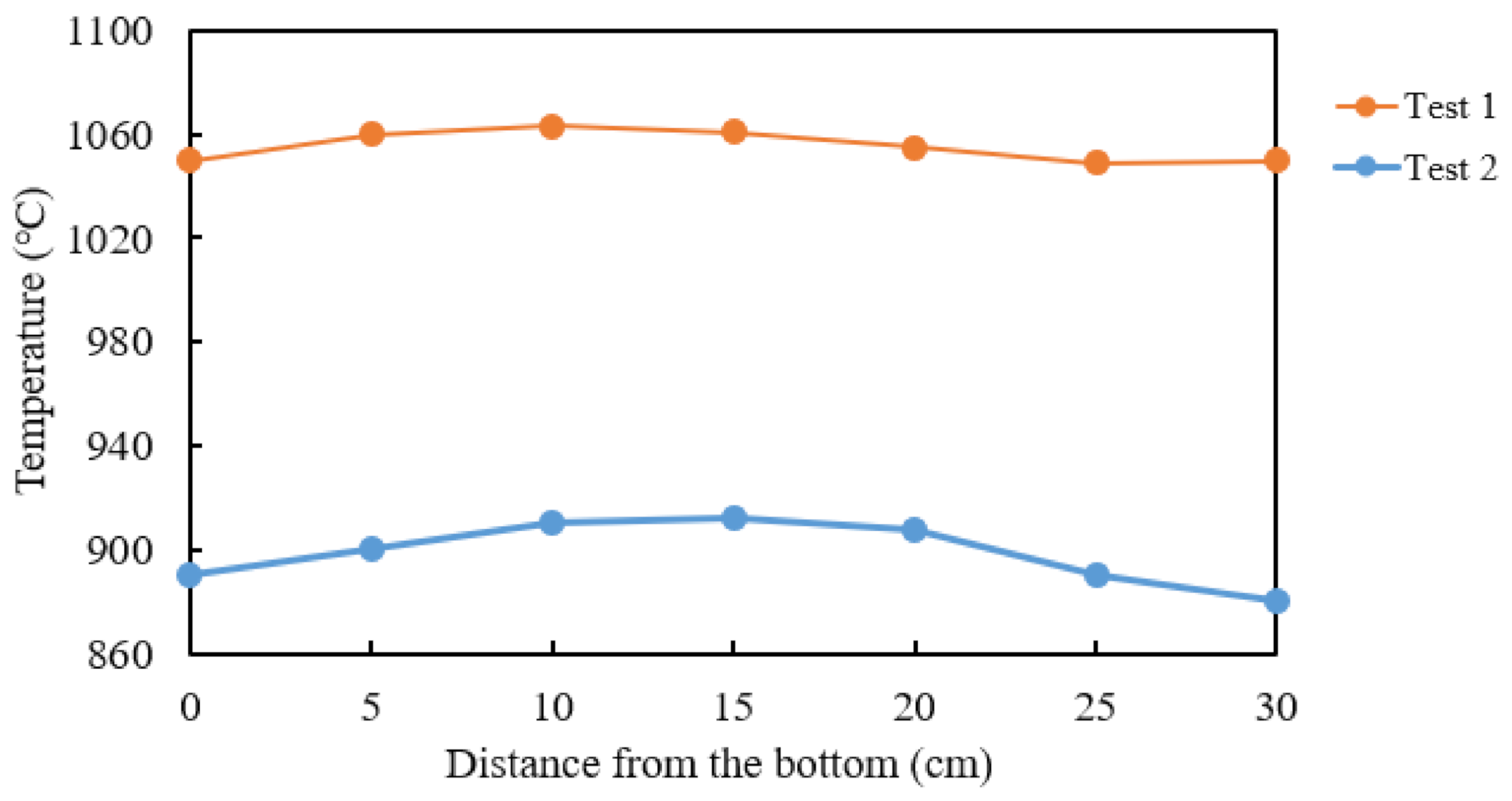
The thermoelement used is a S type thermocouple, which is used for high temperature applications, and has a high accuracy and stability [28]. It is placed inside a protective ceramic tube and consists of platinum rhodium—10% Pt. The thermocouple is placed almost centered in the crucible. The distribution of heat inside the crucible when the furnace was running was measured. This was done by heating the furnace up, and then pulling the thermocouple out, pausing every 5 cm to measure the temperature at said spot. The results can be seen in Figure 2.
A total of 350 g of the crushed sample (accuracy 0.1 g) was homogeneously distributed inside the crucible and the lid was fastened on top with screws before it was placed in the ENTECH furnace. The crucible was placed in the ENTECH furnace and water cooling and gas tubes were fastened at the bottom of the crucible. Thermoelements were inserted into the crucible through a pipe on the lid. The fan and water cooling were turned on, and the purging of argon gas was initiated. The furnace was thereafter turned on and consequently the heating of charcoal commenced.
Argon was purged through the crucible whilst the charcoal was heated to the predetermined temperature, at rates 3 L/min at standard temperature and pressure (STP), with ramping time 20 °C/min to 500 °C and with 10 °C/min to 1100 °C. Some experiments were only heated with Ar, to compare the material that was heated only to the material that was densified with methane. For the Ar experiments, when the predetermined temperature was reached, the furnace was turned off, and the crucible with charcoal was left in the furnace to cool, with purging gas still turned on. When the temperature was below 200 °C, the gas was turned off, and crucible with charcoal inside was left to cool in the furnace overnight. After that, charcoal sample was removed from the crucible, weight loss registered and the particles inspected visually. For the methane experiments, after the initial heating step with argon as purging gas, argon is switched with methane, having a flow rate of 3 L/min (STP). The temperature was kept as stable as possible for 90 min whilst methane was purged through the crucible. When the holding hour was over, the furnace was turned off, and the crucible were cooled using argon gas with a flow rate of 3 L/min (STP) until the temperature was below 20 °C, then the gas was turned off. The crucible with charcoal inside cooled in the furnace overnight, thereafter the charcoal sample was removed from the crucible. The sample were weighed again to record weight loss. An overview of the experiments that were conducted and both the measurements of mass reduction and the deposition can be seen in Table 1. The difference between mass reduction of materials under Ar and the mass reduction under Ar followed by methane would give us the carbon deposition percentage.
2.2.2. Characterization Methods
The volatile matter content of material was measured according to DIN 51720. Ash content of coke and its derivatives was measured according to DIN 51719, whereas the ash content of charcoal samples was determined according to DIN EN 14775. Fixed carbon content was calculated by difference (Fixed carbon = 100% − ash content − volatile matter content).
Elemental analysis of the feedstocks and solid residues was performed on an Elemental Analyser 2400 CHNS/O Series II (Perkin Elmer, Waltham, MA, USA) by Analytik-Service Gesellschaft mbH. Acetanilide was used as a reference standard. Sulfur content was investigated for metallurgical coke according to ASTM D 4239:2017. Oxygen content was calculated by difference, in which ash content from the proximate analysis was used.
SEM analysis of the raw and densified charcoal was conducted on a high-resolution microscope ULTRA 55 (Zeiss, Oberkochen, Germany) under high vacuum in order to understand structural properties of the heat-treated material.
The CO2 reactivity test was carried out in thermogravimetric analysis (TGA) (SINTEF, Trondheim, Norway). A composition of 50% CO2 and 50% CO and a temperature of 1070 °C were chosen for this study. The sample amount (30–40 g) was placed in the stainless-steel crucible. The reaction was stopped at weight loss corresponding to when 20% of the fixed carbon was reacted. The required weight loss was calculated from proximate analysis (volatiles, ash and fixed carbon). The reaction was stopped by purging with inert gas and withdrawal of the sample.
The porosity of charcoal was calculated by the apparent and absolute density of the material according to Equation (3). The absolute density (also known as skeletal density) was determined using a Helium Pycnometer Accupyc II 1340 (MicroMetrics, Norcross, USA). The apparent density (also known as envelope density) was calculated for carbon cubes. The edge length of the cube was measured by a caliper (readability: 0.01 mm) and mass of the particles was determined by an analytical balance (readability: 0.0005 g).
3. Results
3.1. Material Composition
The proximate and ultimate analysis as well as porosity and density of the unreacted coke and charcoal samples are shown in Table 2. The volatile matter content of the charcoal samples was in the range of 13.08–16.75% and revealed a primary heat treatment temperature between 500 and 700 °C [29]. The fixed carbon of charcoals ranged from 80.50% to 85.17%, while the fixed carbon of metallurgical coke was 87.9%.
3.2. Carbon Deposition
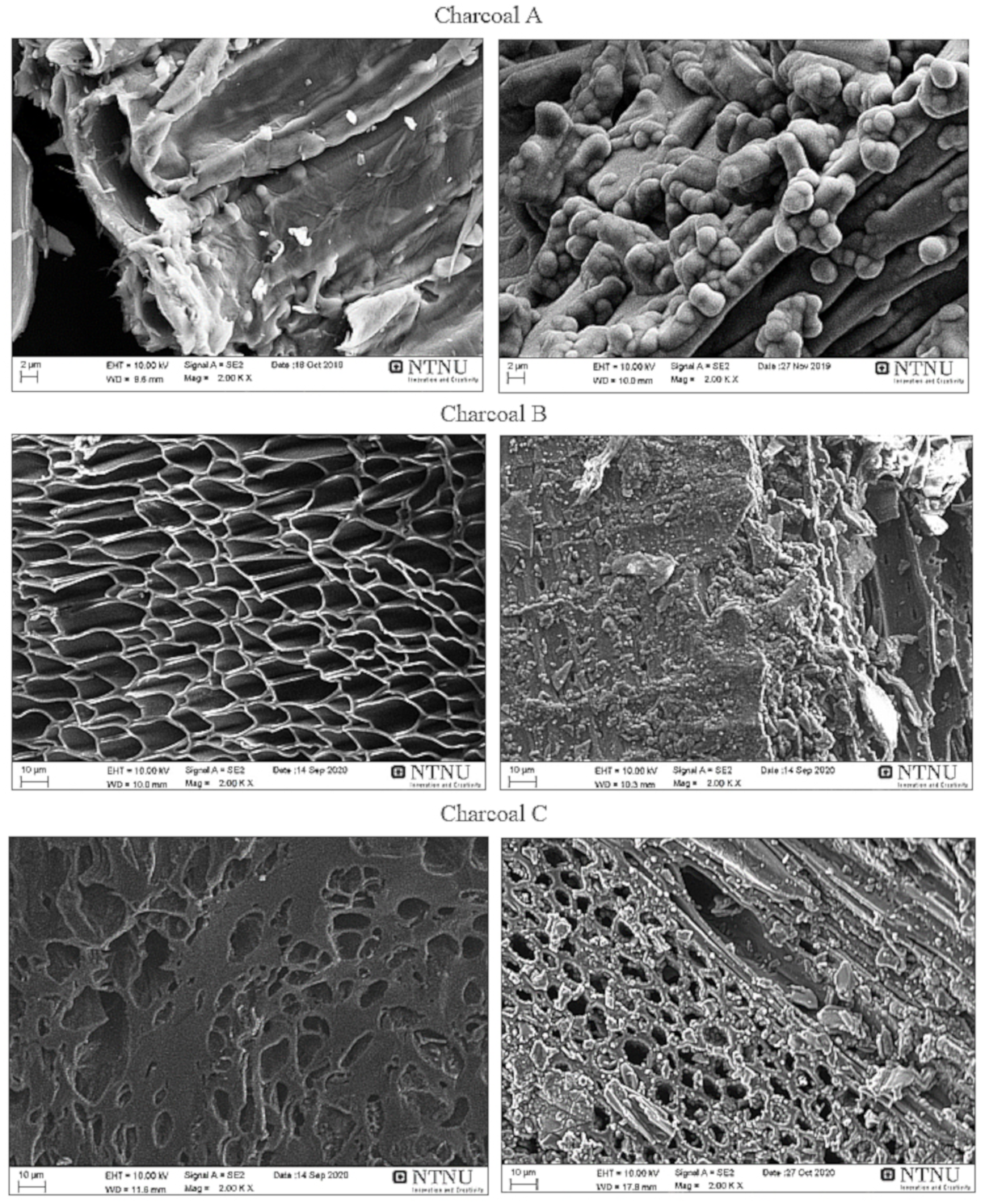
A summary of the mass reduction and deposition measurements was shown in Table 1. The mass reduction of the charcoals prior to carbon deposition for charcoal A, B and C was 17%, 39% and 26%, respectively. The mass reduction of the samples which were under Ar gas flow and methane afterwards, was 2.8%, 26% and 11% for charcoals A, B and C, respectively. It can be seen in Table 1 that charcoal B has the highest mass reduction during heating under Ar gas flow and we know from Table 2 that charcoal B has the highest amount of volatile matter followed by charcoal C and charcoal A, where 13–15% carbon was deposited in the charcoals. The surface of the raw and densified charcoals was investigated by scanning electron microscopy, as it shown in Figure 3. The charcoal pores are clearly visible on raw charcoal images before densification. After densification, carbon which is produced by cracking of methane was deposited on charcoals. The deposited carbon has a round shape, which covered the surface of charcoals as well as inside of the pores. Layers of deposited carbon had been formed on all 3 charcoals and the highest amount of carbon was deposited on charcoal C but since it slightly differs from charcoals A and B, the difference could not be seen in scanning electron microscopy (SEM) images.
3.3. CO2 Reactivity
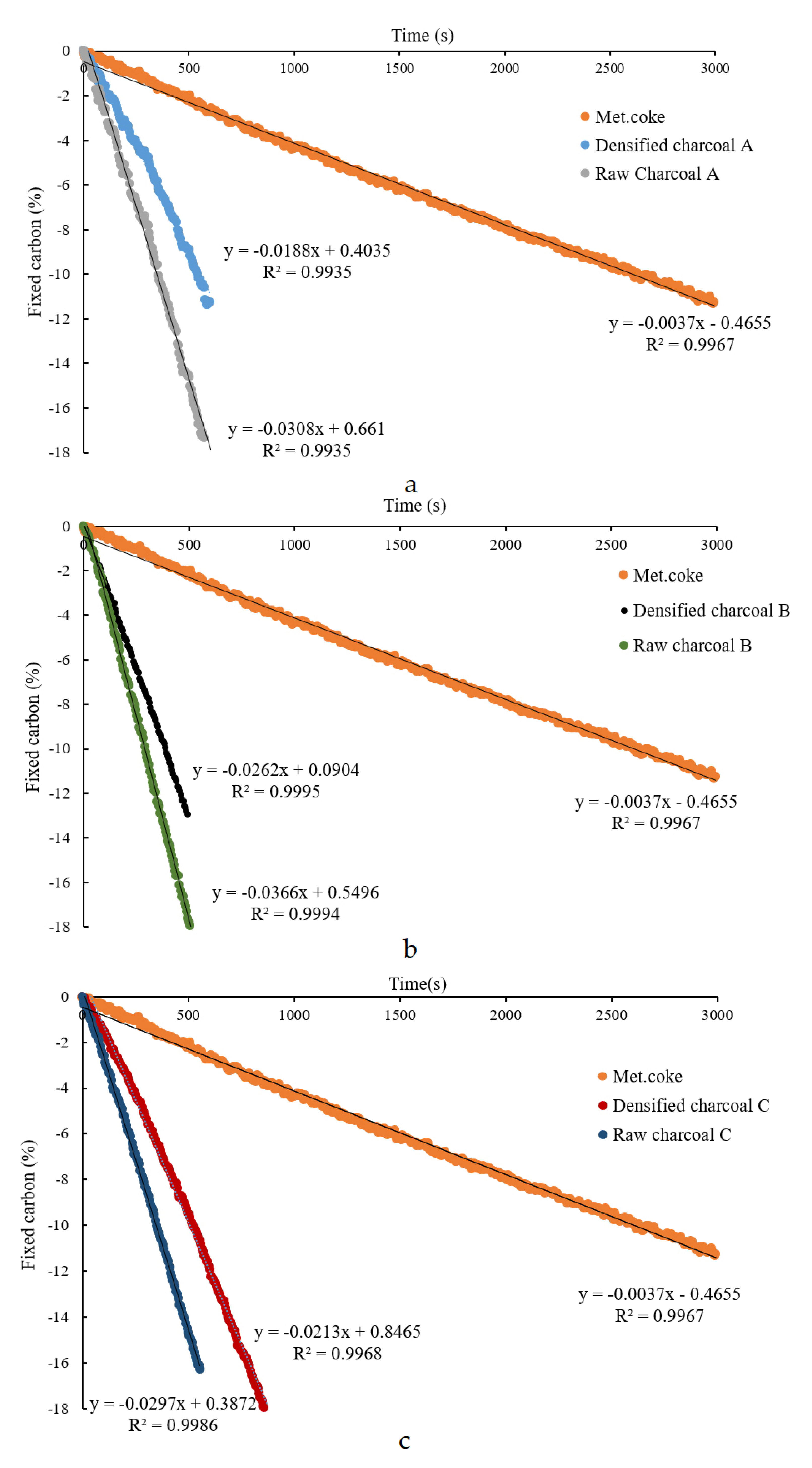
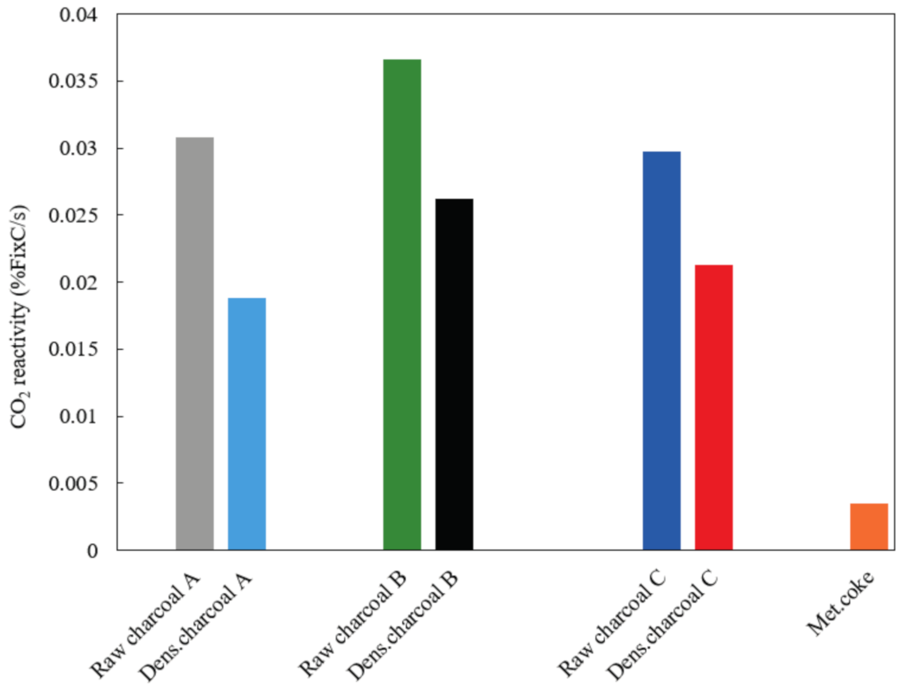
The results of CO2 reactivity for all raw and densified charcoal samples and metallurgical coke are summarized in Figure 4. Using the slope of the curve for the recorded weight measurements during oxidation with CO2, the fraction of reacted fixed carbon per time was calculated. The slope was defined as the CO2-reactivity. The CO2 reactivity of metallurgical coke was added as a reference case. Figure 5 shows a comparison of different charcoals and metallurgical coke at 1070 °C. It shows that the CO2 reactivity decreased by densification by 35%, 30% and 28% for charcoal A, B and C. However, the CO2 reactivity still remained more than 5 times larger than that of metallurgical coke.
3.4. Porosity and Density
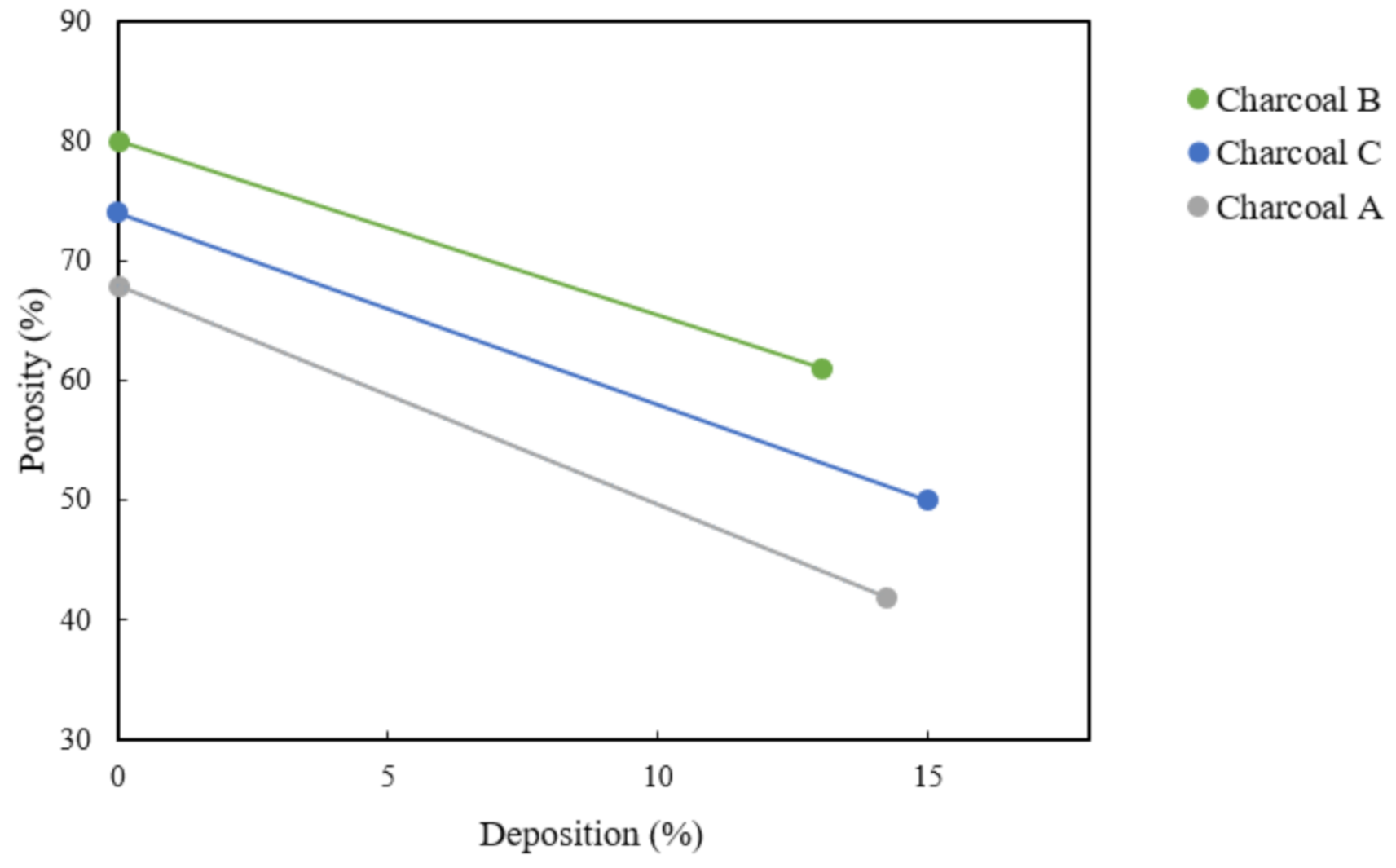
Figure 6 shows the porosity of charcoals before and after densification. The porosity of charcoal A decreased from 68% to 42% after the deposition of 14%. The porosity of raw charcoal B was 80% and after 13% deposition it decreased to 61% while the porosity of raw charcoal C was 74% and it reduced to 50% after 15% carbon deposition. Charcoal B has the most volatiles and after densification, it showed the highest porosity. It can be seen that all the 3 types of charcoal followed the same trend. The porosity and density of different charcoals before and after densification are shown in Table 3 and it can be seen that the density of all samples increased slightly after densification.
4. Discussion
Densification of charcoal has been achieved using carbon from methane. It was shown that methane decomposed at experimental temperatures (1100 °C) and that the carbon deposited on charcoals increased by 13–15%. For the final analysis, 55 g of carbon on charcoal A, 50 g on Charcoal B and 51 g on charcoal C was decomposed and with a CH4 gas flow rate of 3 L/min, 193 g CH4 (12/16 is carbon) was then added. That meant 145 g C in the 90 min in each experiment was added. Consequently, the C yield was 55/193 for charcoal A, 50/193 for charcoal B and 51/193 for charcoal C, which is a bit over 25%.
The density of charcoals increased by 7–18%, thereby confirming a carbon deposition. The other reason for the higher density of charcoal might be the shrinkage of material during heating related to the graphitization of charcoal [30]. This was in agreement with the findings of Riva et al. [31], who densified the pellets using pyrolysis oil as binder. It was observed that the density improved considerably.
The porosity of charcoals decreased by 23–38% during densification. This was in agreement with findings of Hu et al. [15], who found that densified biocarbon in comparison with raw biocarbon, e.g., pellets or briquettes, have lower porosity and increased density. However, Huo et al. [32] used mechanical force to make pellets and briquets and found that it is different from using chemically densified biocarbon. It was also found by Huo et al. [32] that the high porosity and fragile structure of charcoal lead to poor mechanical structure and hence, in manganese production, the biocarbon fed into the furnace might break into small pieces and lead to fines that are released together with flue gas without actually being involved in the metal production process.
CO2 reactivity of all 3 types of charcoal decreased during densification and this was probably because the lower porosity resulted in a lower surface area and less accessible active sites, which is also a result of increased density. Carbon Black in itself also has a lower CO2 reactivity compared to charcoal, which would lower the reactivity. During a densification process, the biocarbon will decrease the porosity and surface area due to the carbon deposition and interlocking of particles with the surrounding ones. As a result of this, a densified charcoal has low gas pores. It was also in agreement with the findings of Hu et al. [15], who found that the CO2 reactivity of biocarbon briquettes is much lower than that of raw biocarbon because of limiting transportation and diffusion of reactive CO2 into biocarbon briquette due to lower porosity and higher density. It was also mentioned by Kawakami et al. [18] that the reactivity of densified biocarbon toward CO2 is expected to be considerably different than that of raw biocarbon, due to increased density and a lower porosity and surface area. Riva et al. [31] also found that with densifying biocarbon pellets using pyrolysis oil, the CO2 reactivity decreased. However, the CO2 reactivity of densified charcoals are still 5–7 times higher than that of metallurgical coke. Biomass is normally low in ash content, especially sulfur, but often biomass has a greater alkali metal content than coke. The products with a high alkali metal content exhibit a greater CO2 reactivity compared with the alkali metal lean carbon samples [32,33,34]. Potassium is a catalyst for the Boudouard reaction and enters the furnace as components of the manganese ore and to a smaller extent also as a component of the coke. Alkalis are known to accumulate and re-circulate in the furnace and may condense on the coke in the upper parts. Potassium speeds up the Boudouard reaction several times [11,12] and remove some of the differences between CO2 reactivities for charcoal and coke.
5. Conclusions
This study, industrial biocarbons were densified using carbon from methane and the goal was to improve the properties of charcoal to enable it to be used in the ferromanganese production industry. Results showed that carbon from methane was deposited on charcoal at rates of up to 15%. The porosity of charcoals decreased by up to 38% after densification and reached more or less the density of metallurgical coke. Charcoals density increased slightly by 7–18% after densification. Densified biocarbon evidently has different CO2 gasification reactivity. A lower porosity and higher density of biocarbon after densification decreased the CO2 reactivity. This is probably the main factor hindering the CO2 reactivity of densified biocarbon. The results of the present work show that it is feasible to densify biocarbon and achieve better physical properties using carbon from methane. The CO2 reactivity of densified charcoal is still much higher than that of metallurgical coke. However, with the use of densifying charcoal, there is a trend toward lower differences between charcoal and metallurgical coke.
Author Contributions
Conceptualization, H.K., G.R.S. and M.T.; methodology, H.K.; validation, H.K.; formal analysis, H.K.; investigation, H.K.; resources, M.T.; data curation, H.K.; writing—original draft preparation, H.K.; writing—review and editing, M.T. and G.R.S.; visualization, H.K.; supervision, M.T.; project administration, M.T. All authors have read and agreed to the published version of the manuscript.
Funding
This research was funded by Research Council of Norway grant number 90461100. The APC was funded by the Norwegian University of Science and Technology.
Institutional Review Board Statement
Not applicable.
Informed Consent Statement
Not applicable.
Data Availability Statement
The data presented in this study are available on request from the corresponding author.
Acknowledgments
The authors gratefully acknowledge financial support from the Research Council of Norway (Project Code: 90461100).
Conflicts of Interest
The authors declare no conflict of interest. The funders had no role in the design of the study; in the collection, analyses, or interpretation of data; in the writing of the manuscript; or in the decision to publish the results.
Abbreviations
The following abbreviations are used in this manuscript.
| ASTM | American Society of Testing and Materials |
| db | dry basis |
| EAF | Electric Arc Furnace |
| MFC | Material Flow Control |
| NTNU | Norwegian University of Science and Technology |
| SAF | Submerged Arc Furnace |
| SINTEF | Norwegian Institute of Technology |
References
- World Steel Association. Steel’s Contribution to a Low Carbon Future and Climate Resilient Societies—World Steel Position Paper; World Steel Association: Brussels, Belgium, 2017. [Google Scholar]
- Olsen, S.; Monsen, B.; Lindstad, T. Emissions from the Production of Manganese and Chromium Alloys in Norway. In Proceedings of the 56th Electric Furnace Conference, New Orleans, LA, USA, 15–18 November 1998; pp. 1–7. [Google Scholar]
- Lindstad, T.; Olsen, S.; Tranell, G.; Færden, T.; Lubetsky, J. Greenhouse gas emissions from ferroalloy production. In Proceedings of the International Ferro-Alloys Congress XI, New Delhi, India, 18–21 February 2007; pp. 457–466. [Google Scholar]
- Kero, I.; Eidem, P.; Ma, Y.; Indresand, H.; Aarhaug, T.; Grådahl, S. Airborne Emissions from Mn Ferroalloy Production. JOM 2019, 71, 349–365. [Google Scholar] [CrossRef] [Green Version]
- Westfall, L.; Davourie, J.; Ali, M.; McGough, D. Cradle-to-gate life cycle assessment of global manganese alloy production. Int. J. Life Cycle Assess. 2016, 21, 1573–1579. [Google Scholar] [CrossRef] [Green Version]
- Mathieson, J.; Rogers, H.; Somerville, M.; Jahanshahi, S.; Ridgeway, P. Potential for the use of biomass in the iron and steel industry. In Proceedings of the Chemeca 2011, Engineering a Better World, Sydney, Australia, 18–21 September 2011; pp. 1–12. [Google Scholar]
- Sesen, F.E. Practical reduction of manganese oxide. Int. J. Chem. Eng. Appl. 2017, 1, 1–2. [Google Scholar] [CrossRef]
- Lindstad, T.; Monsen, B.; Osen, K.S. How the ferroalloys industry can meet greenhouse gas regulation. In Proceedings of the Infacon XII Congress, Helsinki, Finland, 6–9 June 2010; pp. 63–70. [Google Scholar]
- Ostrovski, O.; Olsen, S.E.; Tangstad, M.; Yastreboff, M. Kinetic modelling of MnO reduction from manganese ore. Can. Metall. Q. 2002, 41, 309–318. [Google Scholar] [CrossRef]
- Measuring Coke Reactivity Index (CRI) and Coke Strength after Reaction (CSR); ASTM Standard: West Conshohocken, PA, USA, 1993.
- Lindstad, T.; Syvertsen, M.; Ishak, R.J.; Arntzen, H.B. The influence of alkalis on the Boudouard reaction. Proceedings of Tenth International Ferro-Alloys Congress, INFACON X, Cape Town, South Africa, 1–4 February 2004; pp. 261–271. [Google Scholar]
- Monsen, B.; Tangstad, M.; Midtgaard, H. Use of charcoal in silicomanganese production. In Proceedings of the International Ferro-Alloys Congress, INFACON X, Cape Town, South Africa, 1–4 February 2004; pp. 392–404. [Google Scholar]
- Ishak, R.J. Reaction kinetics for reduction of manganese ore with carbon monoxide in the presence of carbon. Ph.D. Thesis, NTNU, Trondheim, Norway, 2002. [Google Scholar]
- Monsen, B.; Tangstad, M.; Solheim, I.; Syvertsen, I.; Ishak, R.; Midtgaard, H. Charcoal for manganese alloy production. In Proceedings of the International Ferro-Alloys Congress XI, New Delhi, India, 18–21 February 2007; pp. 297–310. [Google Scholar]
- Hu, Q.; Shao, J.; Yang, H.; Yao, D.; Wang, X.; Chen, H. Effects of binders on the properties of bio-char pellets. Appl. Energy 2015, 57, 508–516. [Google Scholar] [CrossRef]
- Wang, L.; Buvarp, F.; Skreiberg, Ø.; Bartocci, P. A study on densification and CO2 gasification of biocarbon. Chem. Eng. Trans. 2018, 65, 145–150. [Google Scholar]
- Balatinecz, J.J. The potential role of densification in biomass utilization. In Biomass Utilization; Côté, W.A., Ed.; Springer: Boston, MA, USA, 1983; Volume 67, pp. 181–190. [Google Scholar]
- Stelte, W.; Sanadi, A.R.; Shang, L.; Holm, J.K.; Ahrenfeldt, J.; Henriksen, U.B. Recent developments in biomass pelletization a review. BioResources 2012, 7, 4451–4490. [Google Scholar] [CrossRef]
- Kaliyan, N.; Vance Morey, R. Factors affecting strength and durability of densified biomass products. Biomass. Bioenerg. 2009, 33, 337–359. [Google Scholar] [CrossRef]
- Kawakami, M.; Taga, H.; Takenaka, T.; Yokoyam, S. Micro Pore Structure and Reaction Rate of Coke, Wood Charcoal and Graphite with CO2. ISIJ Int. 2004, 44, 2018–2022. [Google Scholar] [CrossRef] [Green Version]
- Biørnstad, O. Reduction Mechanisms in Manganese Ore and Deposition of Carbon from Natural Gas. Master’s Thesis, NTNU, Trondheim, Norway, 2020. [Google Scholar]
- Lindgaard, H. High Temperature Decomposition of Methane on Quartz Pellets. Master’s Thesis, NTNU, Trondheim, Norway, 2017. [Google Scholar]
- Abbas, H.F.; Wan Daud, W.M.A. Hydrogen production by thermocatalytic decomposition of methane using a fixed bed activated carbon in a pilot scale unit: Apparent kinetic, deactivation and diffusional limitation studies. Int. J. Hydrogen Energy 2010, 35, 12268–12276. [Google Scholar] [CrossRef]
- Muradov, N.; Fidalgo, B.; Gujar, A.C.; Garceau, N.; Raissi, A.T. Production and characterization of Lemna minor bio-char and its catalytic application for biogas reforming. Biomass Bioenergy 2012, 42, 123–131. [Google Scholar] [CrossRef]
- Klinghoffer, N.B.; Castaldi, M.J.; Nzihou, A. Catalyst properties and catalytic performance of char from biomass gasification. Ind. Eng. Chem. Res. 2012, 51, 13113–13122. [Google Scholar] [CrossRef]
- Dufour, A.; Celzard, A.; Fierro, V.; Martin, E.; Broust, F.; Zoulalian, A. Catalytic decomposition of methane over a wood char concurrently activated by a pyrolysis gas. Appl. Catal. A Gen. 2008, 346, 164–173. [Google Scholar] [CrossRef]
- Dufour, A.; Celzard, A.; Ouartassi, B.; Broust, F.; Fierro, V.; Zoulalian, A. Effect of micropores diffusion on kinetics of CH4decomposition over a wood-derived carbon catalyst. Appl. Catal. A Gen. 2009, 360, 120–125. [Google Scholar] [CrossRef]
- Type S Thermocouple. 2011. Available online: http://www.thermocoupleinfo.com/type-s-thermocouple.htm (accessed on 3 June 2020).
- Kaffash, H.; Tangstad, M. Factors influencing dissolution of carbonaceous materials in liquid Fe-Mn. J. Iron Steel Res. Int. 2020, 27, 1153–1162. [Google Scholar] [CrossRef]
- Surup, G.; Vehus, T.; Eidem, P.; Trubetskaya, A.; Nielsen, H. Characterization of renewable reductants and charcoal-based pellets for the use in ferroalloy industries. Energy 2019, 167, 337–345. [Google Scholar] [CrossRef]
- Riva, L.; Surup, G.; Buø, T.; Nielsen, H.K. A study of densified biochar as carbon source in the silicon and ferrosilicon production. Energy 2019, 181, 985–996. [Google Scholar] [CrossRef]
- Huo, W.; Zhou, Z.; Chen, X.; Dai, Z.; Yu, G. Study on CO2 gasification reactivity and physical characteristics of biomass, petroleum coke and coal chars. Bioresour. Technol. 2014, 159, 143–149. [Google Scholar] [CrossRef]
- Kapteijn, F.; Abbel, G.; Moulijn, J.A. CO2 gasification of carbon catalysed by alkali metals: Reactivity and mechanism. Fuel 1984, 63, 1036–1042. [Google Scholar] [CrossRef]
- Hussein, A.; Larachi, F.; Ziegler, D.; Alamdari , H. Effects of heat treatment and acid washing on properties and reactivity of charcoal. Biomass Bioenergy 2016, 90, 101–113. [Google Scholar] [CrossRef]
- Kicinski, W.; Dyjak, S. Transition metal impurities in carbon-based materials: Pitfalla, artifacts and deleterious effects. Carbon 2020, 168, 748–845. [Google Scholar] [CrossRef]
- Ahmed, S.; Aitani, A.; Rahman, F.; Al-Dawood, A.; Al-Muhadish, F. Decomposition of hydrocarbons to hydrogen and carbon. Appl. Catal. A-Gen. 2009, 359, 1–24. [Google Scholar] [CrossRef]
Figure 1.
Side view of steel crucible, in accordance with [18].
Figure 1.
Side view of steel crucible, in accordance with [18].

Figure 2.
Temperature distribution in the crucible.

Figure 3.
Scanning electron microscopy (SEM) images of raw (left) and densified (right) charcoals A, B and C.
Figure 3.
Scanning electron microscopy (SEM) images of raw (left) and densified (right) charcoals A, B and C.

Figure 4.
CO2 reactivity of raw and densified charcoals for (a) charcoal A, (b) charcoal B and (c) charcoal C. CO2 reactivity of metallurgical coke was added to all 3 scenarios as the reference case.
Figure 4.
CO2 reactivity of raw and densified charcoals for (a) charcoal A, (b) charcoal B and (c) charcoal C. CO2 reactivity of metallurgical coke was added to all 3 scenarios as the reference case.

Figure 5.
Summary of CO2 reactivity at 1070 °C of raw and densified charcoals and metallurgical coke.
Figure 5.
Summary of CO2 reactivity at 1070 °C of raw and densified charcoals and metallurgical coke.

Figure 6.
Porosity of charcoals before and after densification.


Table 1.
Overview of conducted experiments.
| Material | Temperature (°C) | Purging Gas 3 L/min (STP) | Holding Time(min) | Mass (g) Before | Mass (g) After | Mass Reduction(%) | Deposition (%) |
|---|---|---|---|---|---|---|---|
| Charcoal A | 1100 | Ar | - | 350 | 290 | 17% | - |
| Charcoal A | 1100 | CH4 | 90 | 350 | 340 | 2.8% | 14.2 |
| Charcoal B | 1100 | Ar | - | 350 | 215 | 39% | - |
| Charcoal B | 1100 | CH4 | 90 | 350 | 260 | 26% | 13 |
| Charcoal C | 1100 | Ar | - | 350 | 260 | 26% | - |
| Charcoal C | 1100 | CH4 | 90 | 350 | 310 | 11% | 15 |
Table 2.
Proximate and ultimate analysis of the feedstock materials.
| Material | Charcoal A | Charcoal B | Charcoal C | Metallurgical Coke |
|---|---|---|---|---|
| Proximate analysis (wt.%, db) | ||||
| Volatile | 13.08 | 16.75 | 15.79 | 0.90 |
| Fixed carbon | 85.17 | 80.50 | 81.60 | 88.20 |
| Ash | 1.75 | 2.75 | 2.61 | 10.90 |
| Ultimate analysis (wt.%, db) | ||||
| C | 85.5 | 83 | 83.58 | 87.7 |
| H | 1.95 | 3.14 | 2.4 | 0.21 |
| N | <0.5 | 0.26 | 0.21 | 1.75 |
| O | 10.4 | 10.8 | 11.2 | ˂0.10 |
| S | n.s. | n.s. | n.s. | 0.57 |
| Ash analysis (wt.%, db) | ||||
| SiO2 | 33.4 | 36.8 | 15.3 | 6.29 |
| TiO2 | 0.02 | 0.09 | 0.01 | 0.10 |
| Al2O3 | 0.4 | 1.3 | 0.3 | 2.84 |
| Fe2O3 | 0.4 | 0.7 | 2.4 | 0.68 |
| CaO | 30.6 | 34.7 | 41.7 | 0.39 |
| MgO | 7 | 8.2 | 9 | 0.18 |
| MnO | 3.39 | 0.35 | 3.20 | 0.01 |
| Na2O | 0.34 | 0.27 | 0.37 | 0.08 |
| K2O | 18.06 | 12.70 | 21.01 | 0.23 |
| P2O5 | 6.44 | 4.65 | 6.65 | 0.10 |
| Physical characteristics | ||||
| Porosity (%) | 68 | 80 | 74 | 44–55 |
| Density (g/cm3) | 0.5 | 0.44 | 0.56 | 0.9–1.1 |
Table 3.
Density of charcoal before and after densification. Density of metallurgical coke (met.coke). Density and porosity of the coke was added from other work of the author [29].
Table 3.
Density of charcoal before and after densification. Density of metallurgical coke (met.coke). Density and porosity of the coke was added from other work of the author [29].
| Sample | Density (g/cm3) | Porosity (%) | ||
|---|---|---|---|---|
| Raw | Densified | Raw | Densified | |
| Charcoal A | 0.50 | 0.54 | 68 | 42 |
| Charcoal B | 0.48 | 0.52 | 80 | 61 |
| Charcoal C | 0.56 | 0.60 | 74 | 50 |
| Met. coke | 0.9–1.1 [29] | 44–55 [29] | ||
Publisher’s Note: MDPI stays neutral with regard to jurisdictional claims in published maps and institutional affiliations. |
© 2021 by the authors. Licensee MDPI, Basel, Switzerland. This article is an open access article distributed under the terms and conditions of the Creative Commons Attribution (CC BY) license (http://creativecommons.org/licenses/by/4.0/).
Share and Cite
MDPI and ACS Style
Kaffash, H.; Surup, G.R.; Tangstad, M. Densification of Biocarbon and Its Effect on CO2 Reactivity. Processes 2021, 9, 193. https://doi.org/10.3390/pr9020193
AMA Style
Kaffash H, Surup GR, Tangstad M. Densification of Biocarbon and Its Effect on CO2 Reactivity. Processes. 2021; 9(2):193. https://doi.org/10.3390/pr9020193
Chicago/Turabian StyleKaffash, Hamideh, Gerrit Ralf Surup, and Merete Tangstad. 2021. "Densification of Biocarbon and Its Effect on CO2 Reactivity" Processes 9, no. 2: 193. https://doi.org/10.3390/pr9020193
Note that from the first issue of 2016, this journal uses article numbers instead of page numbers. See further details here.