Article

Microstructural and Corrosion Properties of Ti-to-Zr Dissimilar Alloy Joints Brazed with a Zr-Ti-Cu-Ni Amorphous Filler Alloy

1
Department of Materials Science and Engineering, Ulsan National Institute of Science and Technology (UNIST), Ulsan 44919, Korea
2
Department of Convergence Technology for Heavy Industries, University of Ulsan, Ulsan 44610, Korea
3
Welding & Joining Research Department, Korea Shipbuilding & Offshore Engineering, Ulsan 44032, Korea
4
School of Materials Science and Engineering, University of Ulsan, Ulsan 44776, Korea
*
Authors to whom correspondence should be addressed.
The authors contributed equally to this work.
Metals 2021, 11(2), 192; https://doi.org/10.3390/met11020192
Submission received: 22 December 2020 / Revised: 13 January 2021 / Accepted: 18 January 2021 / Published: 21 January 2021

Abstract

:
Titanium and Zircaloy-4 dissimilar alloys were brazed with a zirconium-titanium-copper-nickel amorphous filler alloy, and the resulting joint structures as well as their corrosion properties were examined. The microstructure of the brazed joints was investigated according to brazing holding time at 850 °C, and the corrosion property was analyzed by potentiodynamic polarization. During brazing, joints were produced by diffusion-induced isothermal solidification of the molten filler alloy. At a relatively brief brazing holding time of 5 min, a large segregation zone consisting of an active α-phase and a nobler intermetallic phase was generated in the joint center, which suffered from micro-galvanic corrosion. The presence of alloyed titanium deteriorated the nobility of the α-zirconium phase near the joint and induced galvanic coupling with cathodic base metals, resulting in massive localized corrosion. This localized corrosion caused the pitting behavior at the applied potential of −51.1~187.5 mV during anodic polarization. With a brazing holding time of 20 min, the concentration of the alloying elements was homogenized to eliminate the electrochemical potential difference and minimize the galvanic corrosion susceptibility of the joint region. This homogeneous joint resulted in a highly passive corrosion behavior comparable to that of the titanium base metal.

1. Introduction

Titanium (Ti) is the material of choice for applications involving corrosive environments, such as power generation and chemical processing, due to its high specific strength and outstanding resistance to corrosion [1,2]. Zirconium (Zr) is also resistant to corrosion, and has been widely used in the nuclear industry [3,4]. With the expanding use of both materials, interest has grown in developing a composite of the two, potentially combining their distinct advantages [5,6]. Enhanced strength reportedly can be obtained from a multilayered composite, due primarily to the hardening effect of interfacial Ti-Zr mutual diffusion layers [5,7].
Brazing is an applicable solid-state process for joining dissimilar metals or alloys [8,9]. To braze Ti and Zr, Zr-rich amorphous alloys have been widely investigated as promising fillers that contain Ti, with copper (Cu), nickel (Ni), iron (Fe), and/or aluminum (Al) added as a melting-point depressant [9,10]. These alloys are considered the best choices for high-temperature and corrosive environments, compared with other types of brazing filler, such as Al- and silver-based alloys [10,11]. Based on their chemical compatibility with Ti and Zr, investigations have been conducted on the brazing of Ti alloys for aerospace and chemical plant applications [10,12], and more recently, the brazing of Zr alloys in nuclear applications [13,14].
Among various Zr-rich amorphous alloys, Zr-Ti-Cu-Ni quaternary systems with multi-component eutectic compositions exhibit relatively low melting temperatures of approximately 800 °C, which reduces the brazing temperature to below 850 °C [10,14]. Such a low brazing temperature would be promising for Ti-to-Zr dissimilar joining. This allows us to prevent unwanted α–β phase transformation of Ti and Zr as well as grain growth of both the base metals during brazing [10]. Intermetallic formations can be minimized by reducing thermally activated interfacial reactions in the brazed joints [12]. Despite these advantages of the Zr-Ti-Cu-Ni amorphous alloys, the study has been limited to the brazing of similar Ti or Zr alloys so far, and microstructural investigation has not been performed on the dissimilar brazing between Ti and Zr alloys. To obtain the proper properties of the Ti-to-Zr joints, the process parameters should be adjusted for the dissimilar brazing, because the microstructural evolution of the dissimilar joints would be different from that of the similar joints.
In addition to low brazing temperatures, the foremost requirement for Ti-to-Zr dissimilar brazing is that the joints should be as resistant to corrosion as virgin base metals under highly corrosive conditions [15,16]. The corrosion resistance of brazed joints depends heavily on the composition of the brazing filler alloys used and the resulting microstructures, as compositional and microstructural heterogeneities can make the joint area relatively more active or passive [16,17]. In particular, the essential alloying elements (e.g., Cu and Ni) in the Zr-rich amorphous alloys may form specific intermetallic phases such as (Ti,Zr)2Cu and (Ti,Zr)2Ni during brazing, due to their limited solubility in both Ti and Zr [14,18]. This multi-phase microstructure can aggravate the galvanic corrosion susceptibility of the Ti-to-Zr dissimilar joints.
The objective of the present study was to apply a Zr-Ti-Cu-Ni amorphous alloy as a brazing filler for Ti-to-Zr dissimilar joining. Particular emphasis was placed on the microstructural evolution at the interface to achieve high corrosion resistance by controlling the joint microstructure. The microstructure of the brazed joints was characterized by the brazing holding time at 850 °C, and the joint corrosion property was investigated by potentiodynamic polarization.

2. Materials and Methods

The base metals used in this study were a commercially pure Ti plate (ASTM B265 grade 1) and a hot-rolled/annealed bar of Zircaloy-4 (ASTM B351, 1.38Sn–0.2Fe–0.1Cr–bal. Zr [wt%]). The tensile strength and elongation of the base metals were 310 MPa and 27% for Ti, and 530 MPa and 30% for Zircaloy-4, respectively. The specimens used for brazing were machined into rectangular blocks with dimensions of 10 mm × 13 mm × 26 mm, and the surfaces to be joined were polished and cleaned ultrasonically in ethanol and acetone. The brazing filler alloy with a composition of 48% Zr, 16% Ti, 17% Cu, and 19% Ni in the form of ribbons was produced by a melt-spinning technique [19]. The thickness of the filler alloy was 30 μm. The melting temperatures, i.e., solidus and liquidus, were 795 and 835 °C, respectively, based on differential scanning calorimetry (DSC; SETARAM Setsys Evo. TG-DSC/DTA).
Infrared heating was employed to join the Ti and Zircaloy-4 specimens [9,14]. An infrared chamber was pre-vacuumed and purged with argon gas at a flow rate of 4 L/min. The infrared heating began at a heating rate of 100 °C/min until the chamber reached 850 °C. The isothermal holding time varied from 5 to 20 min to investigate the time-dependent microstructural evolution of the resulting joints. After turning off the power, the specimen temperature dropped immediately as the furnace wall was not heated by the infrared heating. During the brazing process, the specimens were compressively loaded with 2 kg of pressure to keep all parts in place. Two brazed specimens were prepared for each process parameter.
After brazing, as-joined specimens were cut by a low-speed diamond saw and then subjected to a standard metallographic procedure. Structural and quantitative chemical analyses of the joints employed a field-emission scanning electron microscope (FESEM; JEOL, JSM-7600) coupled with an energy dispersive spectroscope (EDS) at an operating voltage of 15 kV and a spot size of 1 μm. To compare the mechanical properties among various regions in the brazed joints, Vickers micro-hardness testing was carried out with a 10 g load for 10 s at regular intervals of 20 μm. The low load value of 10 g was chosen to measure the hardness values of very narrow joint areas and to avoid the influence from the adjacent indents. Three tests were performed per sample.
Potentiodynamic polarization experiments were performed in an applied potential range of −1.0 to 1.0 V (vs. a saturated calomel electrode) with a scan rate of 0.5 mV/s to investigate the corrosion characteristics of the joined samples in a 3.5 wt% NaCl solution. When pitting occurred, the experiments were stopped at a current density of ~30 mA/cm2. Three experiments were performed per sample. The tests were conducted with reference to the ASTM G5 standard [20], and the results were interpreted based on the ASTM G3 standard [21]. The corroded surfaces were observed using an optical microscope. To explore the nature of the galvanic corrosion of the joined samples, several model alloys simulating the phases present in the joints were prepared using an arc-melting technique [19]. For the model alloys, the open circuit potential (OCP) was measured using a two-electrode electrochemical system.

3. Results

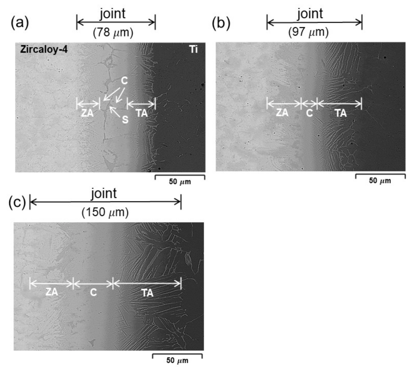
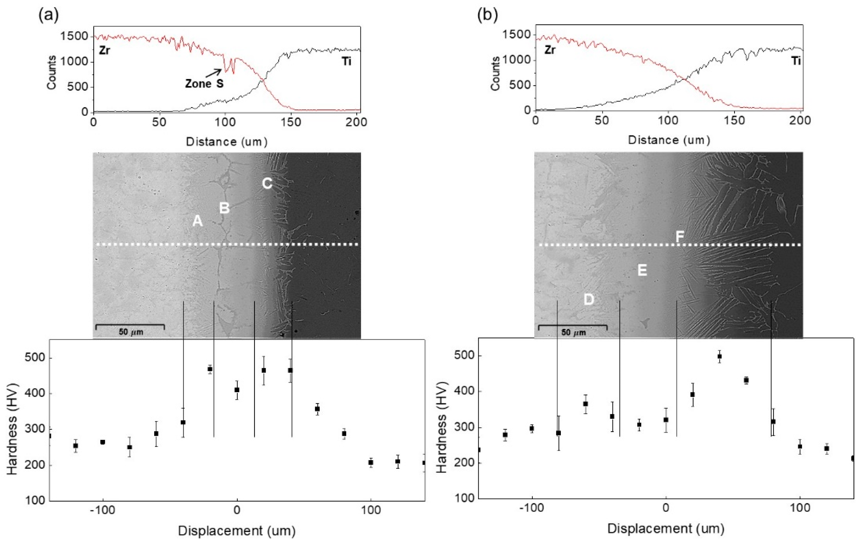
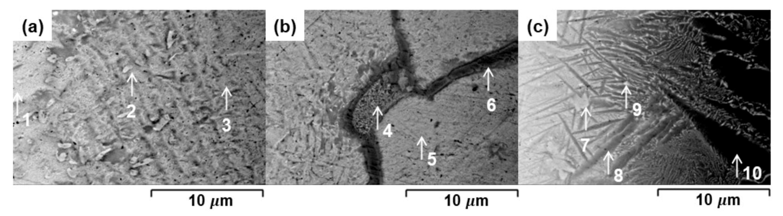
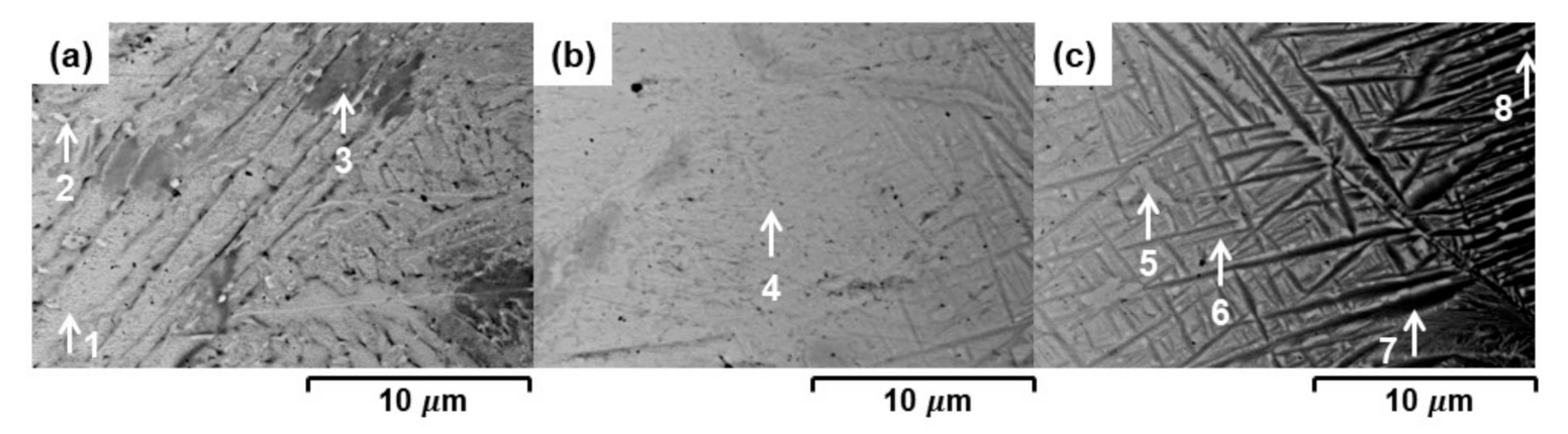
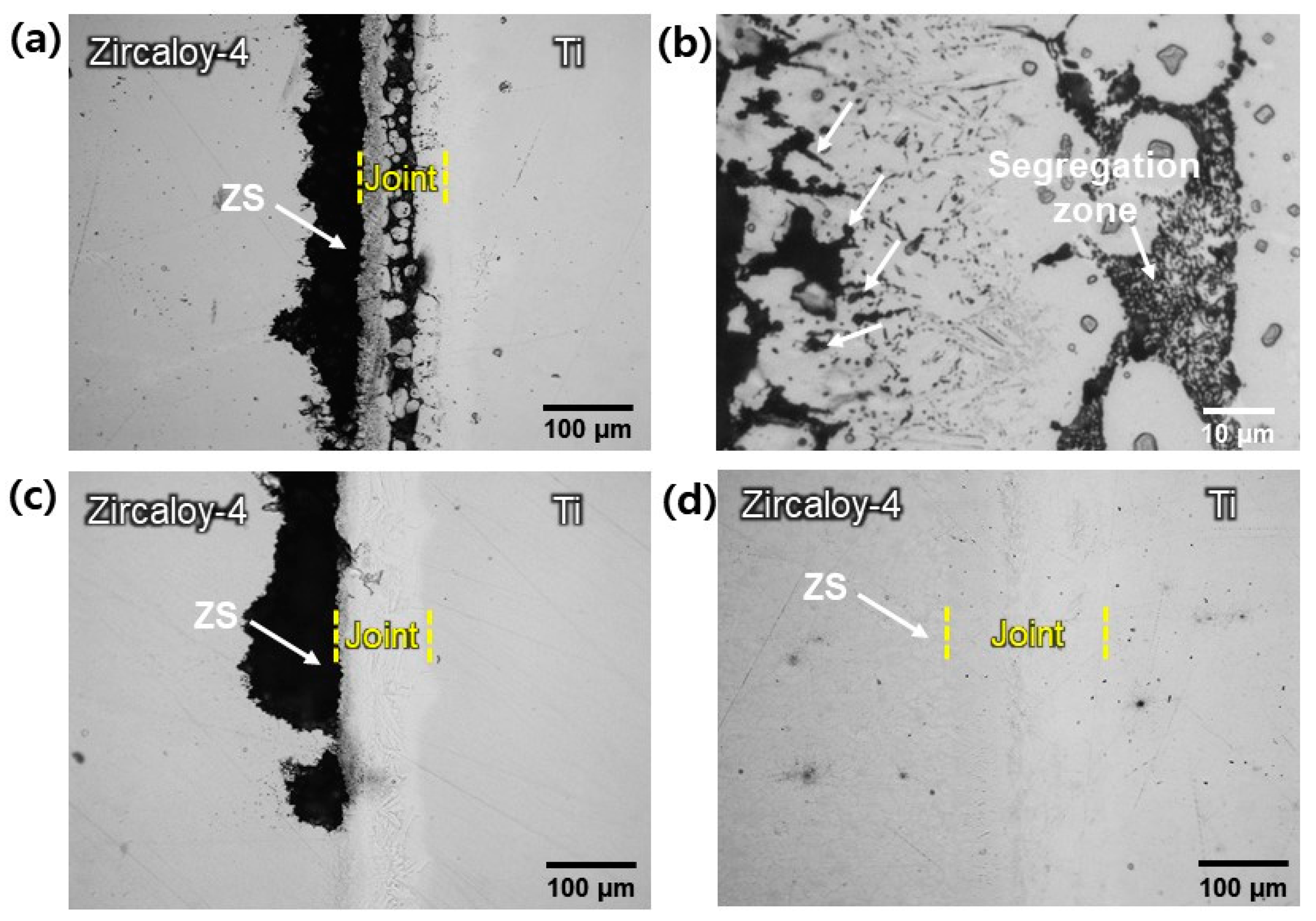
3.1. Microstructure and Hardness of the Joints

Figure 1 shows SEM backscattered electron images (BEIs) for the Ti-to-Zircaloy-4 dissimilar joints brazed by the Zr-Ti-Cu-Ni filler alloy at 850 °C. The Ti and Zircaloy-4 alloys were successfully joined without any pore or void defects in the joint area. Four distinctive regions were produced in the joint brazed for 5 min, as shown in Figure 1a, in which ZA indicates the acicular zone near the Zircaloy-4 base metal, C the central solution zone, S the segregation zone, and TA the acicular zone near the Ti base metal. As the brazing holding time increased, the joints widened considerably with the coarser acicular zones (ZA and TA), due to the enhanced mutual reaction between the molten filler alloy and the base metals. The segregation zone (S) markedly decreased to form tiny isolated islands, as shown in Figure 1b, and completely disappeared from the joint brazed for 20 min, as can be seen in Figure 1c.
The results of EDS-line scanning across the joints brazed for 5 and 20 min are presented in Figure 2. They show that mutual diffusion between the Ti and Zircaloy-4 base metal occurred during brazing, and that the diffusion distance increased considerably with brazing holding time, which is consistent with the general law of a diffusion-controlled process. In Figure 2a, the Zr content drops abruptly in the segregation zone (Zone S), implying the formation of intermetallic phases rather than Zr and Ti solid solutions.
Figure 3 shows enlarged images for the areas indicated in Figure 2a and the corresponding EDS results are summarized in Table 1. The acicular zone near the Zircaloy-4 base metal, indicated by A in Figure 2a, was composed primarily of Zr-rich phases with much less Cu and Ni. Based on the EDS elemental compositions, the proposed phase at points 1 and 3 was α-Zr with different contents of Ti, while the small inclusion of Cu and Ni at point 2 can be explained by the partial formation of a γ-phase by a eutectoid reaction, i.e., β-Zr→α-Zr + γ (γ: Zr-base intermetallic phases such as Zr2Cu and Zr2Ni) by taking into consideration their limited solubility in α-Zr. Similar α + γ two-phase structures in the brazed joints were reported in previous studies [11,14,16,18,19,22]. Points 4 and 6 in Figure 3b correspond to the segregation zone in Figure 1a and this zone contained considerable amounts of Cu and Ni. As both the element pairs of Zr-Ti and Cu-Ni are not only chemically compatible with, but completely soluble in, each other [23], this phase can be regarded as having the formulae of [Zr,Ti]2(Cu,Ni) intermetallic phases [14,24]. The central solution zone, indicated by point 5 in Figure 3b, would be the β-Zr phase alloyed with considerable Ti. A previous study reported that the β-phase appears at room temperature when the Ti content exceeds 20 wt% in a Zr-Ti binary system [25]. Similar to the acicular zone near the Zircaloy-4 base metal, the acicular zone near the Ti base metal, indicated by C in Figure 2a, consisted of the α-Ti phases, points 8 and 10 in Figure 3c, and the γ-phases, which were produced by the eutectoid reaction.
Figure 4 depicts enlarged images for the areas indicated in Figure 2b and the corresponding EDS results are summarized in Table 2. The constituent phases were almost identical to those in the joint brazed for 5 min. The differences between them included the absence of the segregation zone and the coarsening of the microstructure, which can be attributed to enhanced mutual diffusion between the base metals.
The micro-hardness distribution across the joints is presented in Figure 2. Regardless of the brazing holding time, the joints exhibited greater hardness values compared with the base metals. This can be attributed to the hardening effects of the Ti-Zr mutual diffusion layers. The ZA and TA zones in Figure 1 indicate relatively high hardness values due to the formation of fine γ-phase particles, as shown in Figure 3 and Figure 4. The hardness of the C zones was slightly lower than that of the ZA and TA zones, as this zone had no second-phase particles and was only solution-hardened [25].

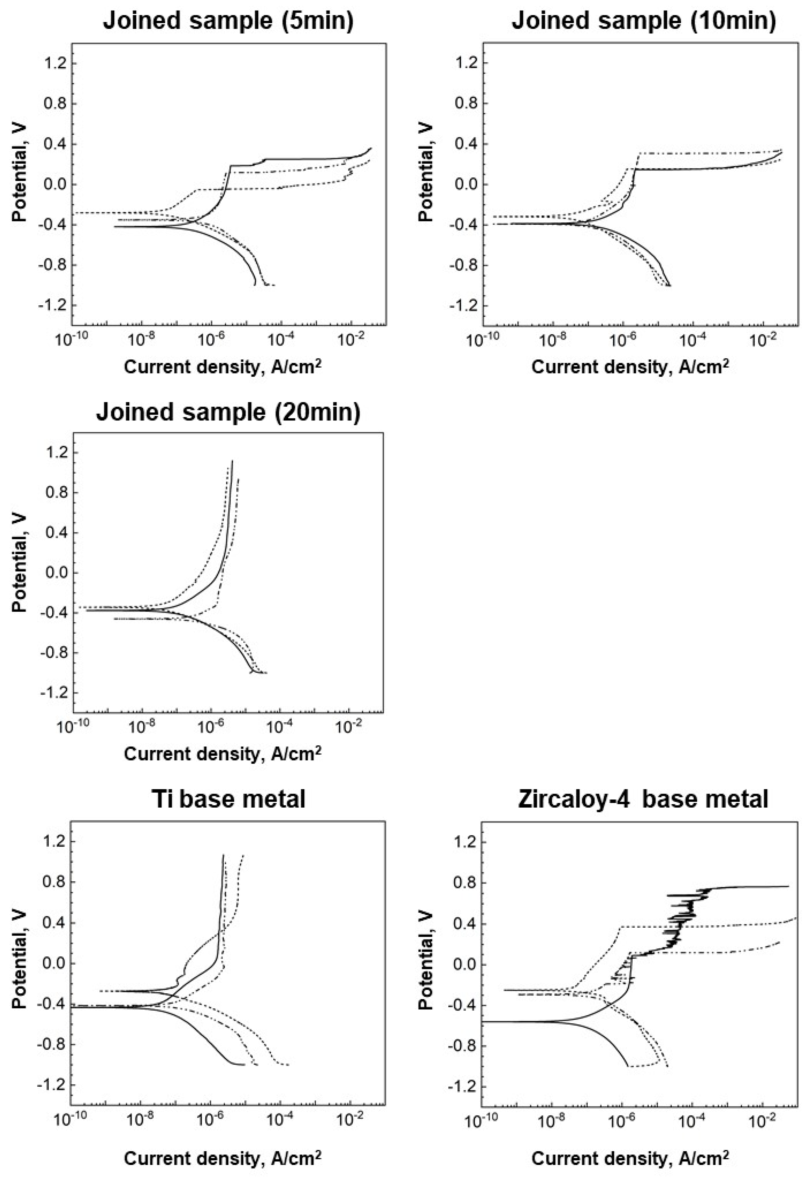
3.2. Potentiodynamic Polarization Results

To study the effect of joint structure on the corrosion property, the joined samples were subject to a potentiodynamic polarization test. The Ti and Zircaloy-4 base metals were compared, and three tests were performed per sample. Figure 5 displays the obtained polarization curves. The joined samples exhibited distinctly different responses to polarization according to brazing holding time. The polarization behavior of the joined sample brazed for 20 min was comparable to that of the Ti base metal. A passive region was clearly observed in the anodic branch, implying the formation of a stable and passive oxide film after a certain amount of general corrosion. However, the joined samples brazed for 5 and 10 min showed pitting corrosion with a dramatic increase in current density due to a small increase in the applied potential. This polarization behavior was similar to that of the Zircaloy-4 base metal.
Table 3 summarizes the corrosion potential (Ecorr), corrosion current (Icorr), and the pitting potential (Epit) determined by the polarization curves in Figure 5. Although the deviations were observed, the Zircaloy-4 base metal generally possessed a relatively small negative Ecorr (samples 2 and 3 in Table 3) compared with the other samples. For the joined samples, the Ecorr values were −456.7 to −281.3 mV, which were comparable to that for the Ti base metal. Unlike the Ecorr values, the difference in Icorr values was not significant from sample to sample, varying by only a few nanoamperes. For the samples with pitting corrosion, the Epit was the lowest in the joined sample brazed for 5 min (−51.1~187.5 mV); this value increased to 145.8~307.7 mV as the brazing holding time increased to 10 min. Eventually, pitting did not occur in the joined sample brazed for 20 min.

4. Discussion

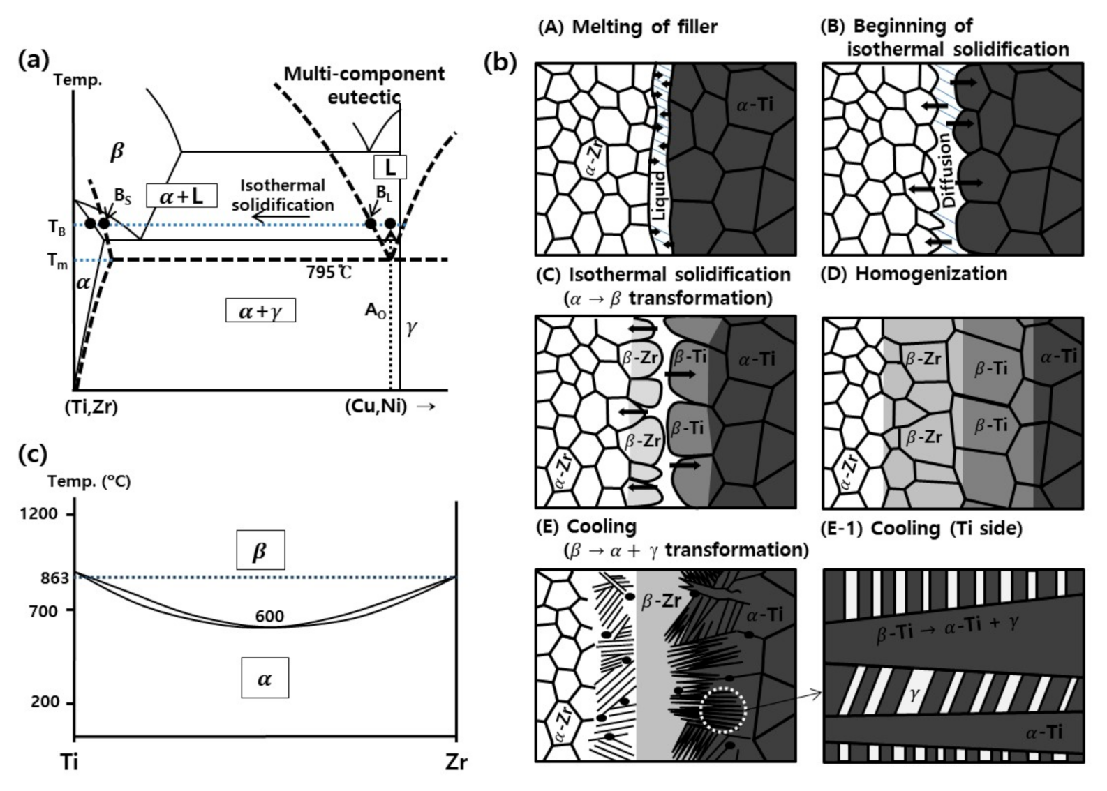
4.1. Microstructural Evolution of the Joints during Diffusion Brazing

As shown in Figure 1 and Figure 2, the joint structure changed gradually as the brazing holding time increased from 5 to 20 min due to an enhanced mutual reaction between the molten filler alloy and the base metals. The joint thickness almost doubled, from 78 to 150 μm. Based on these microstructural features, the observed structural evolution and growth mechanism of the Ti-to-Zircaloy-4 dissimilar joints brazed by the Zr-Ti-Cu-Ni filler alloy can be explained by isothermal solidification through a diffusion reaction between the molten filler alloy and the base metals during brazing, as illustrated in Figure 6 [12,14,24].
Upon heating to the brazing temperature (850 °C), the filler alloy with an initial composition of AO, as depicted in Figure 6a, began to melt and a thin liquid layer formed at the beginning of brazing. Because the Zr-Ti-Cu-Ni amorphous filler alloy provided a much lower melting temperature compared with that of conventional (Ti,Zr)-(Cu,Ni) binary alloys, a molten filler alloy required for brazing can be obtained at a much lower temperature. This low melting temperature is illustrated by the dashed line in the imaginary phase diagram in Figure 6a. Simultaneously with the melting of the filler alloy, the Ti and Zircaloy-4 base metals began to dissolve into the molten filler alloy, as expressed by Stage (A) in Figure 6b. This inward dissolution of the base metals changed the composition of the molten alloy in the vicinity of the Ti base metal toward the Ti-rich BL point in Figure 6a. Similarly, the composition of the molten alloy near the Zircaloy-4 base metal became richer in Zr, with less Cu and Ni. This compositional change increased the liquidus temperature of the molten alloy to the brazing temperature, indicated by TB in Figure 6a, initiating isothermal solidification of the molten filler alloy at the liquid/solid interface, as expressed by Stage (B) in Figure 6b. The primary phases, which were solidified isothermally, were the α-Ti and α-Zr rather than β-Ti and β-Zr, respectively, because the brazing temperature (850 °C) was lower than the β transus of Ti and Zr (882 and 863 °C), as shown in Figure 6a.
When these α-phases with a composition of BS nucleated to grow into the joint, the excessive Cu and Ni elements beyond their solubility in the α-phases should be taken away from the solidification front. As a result, the Cu and Ni elements segregated in the middle of the residual molten alloy at the early stage of brazing. As the brazing proceeded, these segregated elements diffused gradually into the growing α-phases and the base metals. However, outward diffusion of Cu and Ni through the α-phases was sluggish, because α-phases have a close-packed atomic structure and the solubility of Cu and Ni in the α-phases is limited (≈102 ppm for Ni and ≈5 × 10³ ppm for Cu in Zr at 830 °C) [26]. Accordingly, the segregation of Cu and Ni at the central region was rate-controlled by their diffusion into the α-phases. When the brazing holding time was relatively brief, the residual liquid contained greater amounts of Cu and Ni, producing massive segregation at the central region by cooling from Stage (B) or (C) in Figure 6b. During cooling, the residual liquid solidified into a fine dendritic structure by the eutectic reaction of L→α + γ, as anticipated in the imaginary phase diagram in Figure 6a. This inhomogeneous segregation was clearly visible in the joint structure brazed for 5 min, as can be seen in Figure 3b. With a longer isothermal holding after Stage (C), the segregation zone was reduced progressively, due to the increased outward diffusion of Cu and Ni elements. The enhanced dissolution of the base metals also attenuated the concentration of enriched Cu and Ni in the joint. Finally, isothermal holding for 20 min resulted in a joint structure free from such segregation, as shown in Figure 1c.
Together with the outward diffusion of the filler elements (Cu and Ni), the mutual diffusion of the main constituent elements of the base metals (Ti and Zr) was driven by the concentration gradient during brazing, as can be seen in the EDS line-scanning profiles in Figure 2. Both Ti and Zr are completely soluble with each other based on the Ti-Zr binary phase diagram provided in Figure 6c, because they have the same hexagonal close-packed structure and their atomic radii are almost identical [26]. It can therefore be expected that the Ti and Zr elements would actively diffuse toward their counterparts at a brazing temperature of 850 °C. The continuous concentration profiles across the joint in Figure 2 were associated with this active diffusion reaction between the base metals. It was also confirmed that the Ti element diffused toward the Zircaloy-4 base metal, with a large diffusion depth of 100 μm at a brazing holding time of 20 min.
As the Ti base metal was alloyed with the Zr element introduced by the diffusion reaction, the β transus of Ti decreased considerably, as shown in the Ti-Zr binary phase diagram in Figure 6c. Likewise, the β transus of Zr was also lowered by the diffused Ti element. As a result, the β transus of both base metals fell below the brazing temperature (850 °C) by prolonged isothermal holding, and the isothermally solidified α-Ti and α-Zr phases were transformed to the β-Ti and β-Zr phases, as expressed by Stage (C) in Figure 6b. This phase transformation from α to β activated the outward diffusion of the filler elements, because the solubility of Cu and Ni in β-phases is much higher than that in α-phases, as confirmed by the (Zr or Ti)-(Cu or Ni) binary phase diagrams [23]. Consequently, the Cu and Ni elements segregated in the middle of the joint could be transported far from the joint center and the segregation zone could be eliminated completely, as expressed by Stage (D) in Figure 6b. With a further increase in the brazing holding time, the mutual diffusion depth of the Ti and Zr elements was extended and the Cu and Ni elements became increasingly homogenized across the joint. In Ti-to-Zircaloy-4 dissimilar joining, the Cu and Ni elements diffused more deeply into the Ti base metal because the solubility of Cu and Ni in β-Ti is higher than that in β-Zr [23]. As a result, the acicular zone near the Ti base metal (Zone TA) was thicker than that near the Zircaloy-4 base metal (Zone ZA), as shown in Figure 1c.
When the joint was cooled to room temperature after isothermal holding, the β-phase areas near the base metals were transformed into α + γ two-phase structures, as expressed by Stage (E) in Figure 6b. During cooling, the α-phase, which is the equilibrium phase at low temperatures, nucleated from the β-phase and excessive Cu and Ni elements were expelled from the growing α-phase cells or aciculae. The Cu and Ni elements then concentrated in an intercellular region. Finally, this region was decomposed into fine lamellar α + γ structures by the eutectoid reaction of β-phase→α-phase + γ phase, as expressed by Stage (E-1) in Figure 6b. Due to the formation of these fine γ-phases, the acicular zones near the base metals (Zones TA and ZA) exhibited the highest hardness values, as shown in Figure 2b. In the central region, the β-Zr phase was stabilized by a considerable amount of alloyed Ti. As shown in Figure 6c, the β transus can be reduced to 600 °C by alloying the Zr and Ti elements and the metastable β-phase can be preserved even at room temperature without changing into the α-phase during cooling. This result matches that of a previous report in which the β-Zr phase appears at room temperature when the Ti content exceeds 20 wt% in a Zr-Ti binary system [25]. The Vickers micro-hardness in this central solution zone (Zone C) was approximately 300 Hv, as shown in Figure 2b, which is comparable to the value of the β-Zr phase reported in literature [25].

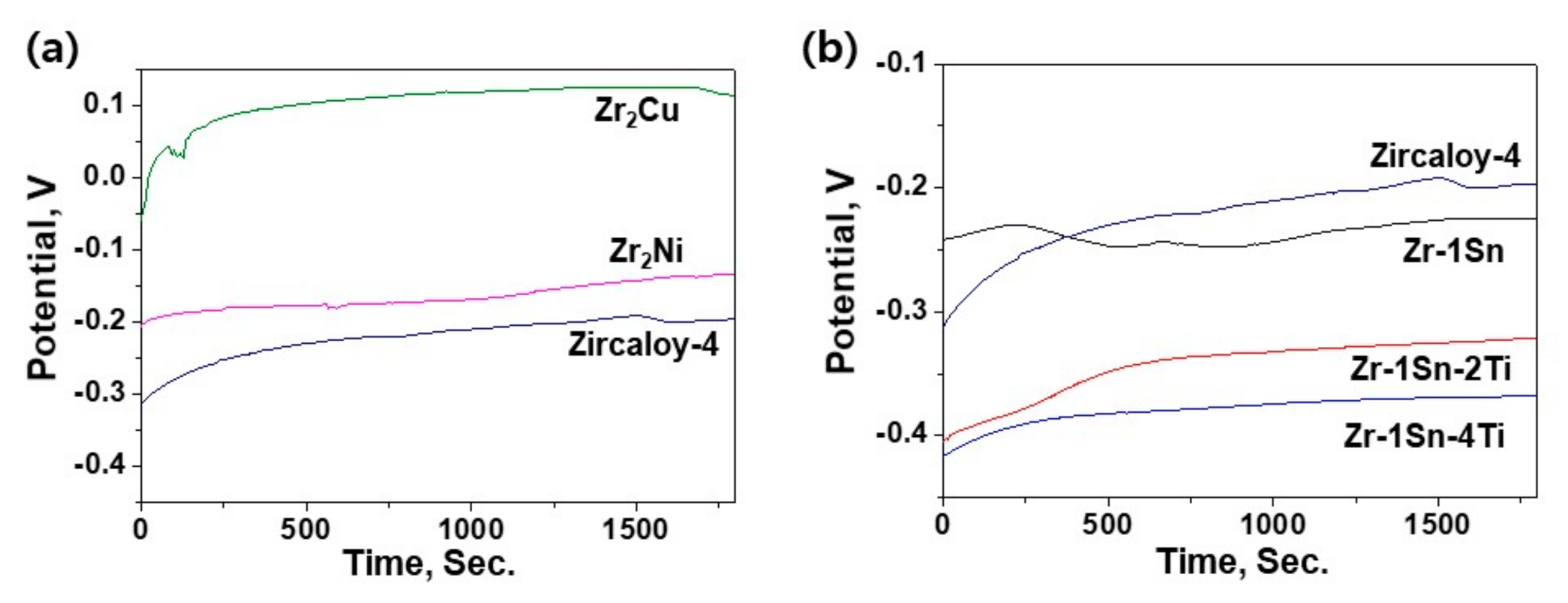
4.2. Corrosion Behavior of the Joints

As shown in Figure 5 and Table 3, variation in brazing holding time led to a significant difference in corrosion properties of the Ti-to-Zircaloy-4 dissimilar joints. Severe pitting corrosion behavior was observed in the joined samples brazed for 5 and 10 min, while the joined sample brazed for 20 min exhibited a clear passivation region in the anodic polarization curve. To clarify the corrosion behavior of the joints in detail, corroded surfaces were examined after the polarization test; corresponding optical microscopy images are presented in Figure 7. In the sample brazed for 5 min, severe localized corrosion occurred in two regions, as shown in Figure 7a. First, the central segregation zone, which is indicated by S in Figure 1a, served as a preferred corrosion site. Similar localized corrosion in the segregation zone has been reported in brazed joints of Ti alloys [12,27]. As shown in Figure 3b and Table 1, the segregation zone consisted of fine dendritic structures containing intermetallic phases with a formula of [Zr,Ti]2(Cu,Ni). These kinds of intermetallic phases are typically considered electrochemically nobler than a Zr-base alloy matrix [19,28]. To verify the effects of such intermetallic phases, the electrochemical stability of model samples, such as Zr2Cu and Zr2Ni, was examined through an OCP measurement. The model samples were prepared using an arc-melting technique [19]. As shown in Figure 8a, the investigated intermetallic phases exhibited higher OCP values compared with the Zircaloy-4 base metal, indicating superior electrochemical nobility. Due to this potential difference, a micro-galvanic cell would be generated between the intermetallic phases and α-Zr dendrite. The α-Zr phase was anodic to the nobler intermetallic phases and the interfacial region suffered from the preferential micro-galvanic attack, as shown in Figure 9a. As a result, the intermetallic particles were detached from the matrix through a material loss at the interfacial region, as expressed in Figure 9b. This corrosion behavior in the segregation zone can be confirmed from the corroded morphology in Figure 7b.
In addition to the central segregation zone, the Zircaloy-4 base metal side (Zone ZS) adjacent to the joint area was severely corroded during the polarization test, as shown in Figure 7a. The intermetallic phases did not appear to be responsible for such massive corrosion, as the corroded region did not possess as many intermetallic phases as the central segregation zone, as can be seen in Figure 3a. In this case, the intermetallic phases acted as small cathodic sites against the large anodic α-Zr area during the polarization test. This phenomenon produced a significant discrepancy with the experimentally observed massive corrosion in the ZS zone. The localized corrosion may also be a product of the composition of the α-Zr phase in the ZS zone. As indicated by point 1 in Table 1, the α-Zr phase near the joint was alloyed with the Ti element coming from the joint area through a diffusion reaction. Although corrosion resistivity increases with Ti concentration in Zr-Ti binary alloys [29], the electrochemical nobility of the α-Zr phase can deteriorate with the addition of Ti when the alloy contains a small amount of tin (Sn), which is an essential element of Zircaloy-4 [19]. The possibility of variation in the electrochemical nobility was evaluated through OCP measurements using several Zr-base model alloys, including Zr-1Sn, Zr-1Sn-2Ti, and Zr-1Sn-4Ti, as shown in Figure 8b. The results clearly show that the OCP values of the Zr-1Sn alloy decreased considerably with an increase in Ti content. In this respect, the presence of Ti enabled the α-Zr phase in the ZS zone to be more active than the joint area as well as the base metals far from the joint. Because the electrochemical potential difference provided a driving force for galvanic corrosion, the ZS zone showed anodic behavior with massive localized corrosion, as depicted in Figure 7a. Because the joined sample was produced by a mutual diffusion reaction during brazing, a concentration gradient of the Ti element was induced in the vicinity of the joint, as shown in Figure 2a, and the Ti content was relatively high near the joint. Accordingly, the interfacial region between the ZS zone and the joint became galvanically unstable first during the polarization test and localized corrosion was initiated at this point. This instability was further aggravated by the presence of the nobler intermetallic phases, as indicated by arrows in Figure 7b. The corrosion initiated near the joint progressed toward the Zircaloy-4 base metal side and ceased at a specific region, where the concentration of the alloyed Ti was insufficient to generate galvanic corrosion, as shown in Figure 7a. Such galvanic corrosion was highly localized by the areal effect of the narrow ZS zone in the joined sample brazed for 5 min. As shown in Figure 2a, the compositional gradient across the joint was relatively steep, due to the limited diffusion reaction during the brief brazing holding time. Consequently, macroscopic galvanic coupling developed between the narrow anodic ZS zone and the much wider cathodic base metal surface, resulting in severe material loss in the depth direction, as shown in Figure 7a.
When the brazing holding time was increased to 10 min, the central segregation zone was reduced considerably (Figure 1b), and localized corrosion was not observed within the joint area, as shown in Figure 7c. However, highly localized corrosion still occurred in the ZS zone, indicating that alloyed Ti in the α-phase made the zone more susceptible to galvanic corrosion, similar to the case of the joined sample brazed for 5 min. However, the joined sample brazed for 20 min exhibited passive polarization behavior (Figure 5), and no evidence of localized corrosion was observed after the polarization test, as shown in Figure 7d. For this joined sample, the brazing holding time was long enough to homogenize the concentration of the alloying elements across the joint through an enhanced mutual diffusion reaction. The Sn content in the α-Zr phase diminished considerably in the ZS zone of the joined sample brazed for 20 min (point 1 in Table 2). Due to the relatively homogeneous distribution of the alloying elements, the ZS zone was expected to exhibit a negligible potential difference from the base metals and be highly resistant to galvanic corrosion. When the mutual diffusion depth of the alloying elements was extended significantly up to 100 μm, the compositional gradient in the vicinity of the joint became moderate, as shown in Figure 2b. This alleviated the areal effect from galvanic corrosion, minimizing the galvanic corrosion susceptibility of the resulting joint. All these factors resulted in the highly passive corrosion behavior of the joined sample brazed for 20 min depicted in Figure 7d.

5. Conclusions

A Zr-Ti-Cu-Ni amorphous alloy was proposed as a low-temperature brazing filler alloy for Ti-to-Zircaloy-4 dissimilar alloy joining, and its brazing characteristics were examined with respect to the produced joint structures and their corrosion properties. The joint structure was evolved by a mutual diffusion reaction between the molten filler alloy and the base metals at a brazing temperature of 850 °C. When the brazing holding time was brief (5 min), a large segregation zone was generated in the joint center due to the limited diffusion reaction, while the joints brazed for longer periods (10 and 20 min) typically consisted of a predominant α + γ acicular structure with a central β-phase solution zone, which was produced by complete isothermal solidification of the molten brazing filler alloy. The joined sample brazed for 20 min showed corrosion resistance comparable to that of the Ti base metal, whereas massive localized corrosion was observed in the joined samples brazed for 5 and 10 min. Distinct pitting behaviors were detected during the polarization experiments at the applied voltages of −51.1~187.5 mV for the joined sample brazed for 5 min, and 145.8~307.7 mV for the joined sample brazed for 10 min, respectively. The central segregation zone consisting of the active α-phase and nobler intermetallic phase suffered from micro-galvanic corrosion. The Zircaloy-4 base metal side adjacent to the joint served as a preferred corrosion site, when the brazing holding time was relatively brief (5 and 10 min). The presence of alloyed Ti weakened the nobility of the α-Zr phase, causing a significant difference in electrochemical potential between this anodic zone and the cathodic base metals. The resulting galvanic coupling was the major driving force for the severe material loss observed in the Zircaloy-4 base metal side. In contrast, after a brazing holding time of 20 min, the concentration of the alloying elements was homogenized sufficiently to eliminate the electrochemical potential difference and minimize the galvanic corrosion susceptibility of the joint region. This homogeneous joint structure resulted in a highly passive corrosion behavior of the joined sample brazed for 20 min.

Author Contributions

Conceptualization, J.G.L. and S.S.P.; methodology, S.-Y.L. and H.-J.L.; validation, S.-Y.L., H.-J.L. and J.-H.B.; formal analysis, S.-Y.L. and J.-H.B.; investigation, J.G.L. and H.-J.L.; resources, J.G.L.; data curation, J.G.L. and S.S.P.; writing—original draft preparation, S.-Y.L. and H.-J.L.; writing—review and editing, J.G.L. and S.S.P.; visualization, S.-Y.L. and J.-H.B.; supervision, J.G.L. and S.S.P.; project administration, J.G.L.; funding acquisition, J.G.L. All authors have read and agreed to the published version of the manuscript.

Funding

This work was supported by the 2018 Research Fund of University of Ulsan.

Data Availability Statement

The data presented in this study are available in article here.

Conflicts of Interest

The authors declare no conflict of interest. The funder had no role in the design of the study; in the collection, analyses, or interpretation of data; in the writing of the manuscript, or in the decision to publish the results.

References

  1. Markovsky, P.E.; Janiszewski, J.; Bondarchuk, V.I.; Stasyuk, O.O.; Savvakin, D.G.; Skoryk, M.A.; Cieplak, K.; Dziewit, P.; Prikhodko, S.V. Effect of strain rate on microstructure evolution and mechanical behavior of titanium-based materials. Metals 2020, 10, 1404. [Google Scholar] [CrossRef]
  2. Zhao, W.; Su, W.; Li, L.; Fang, D.; Chen, N. Evolution of mechanical properties of Ti-6Al-4V alloy in the temperature range of 20 to −196 °C. Met. Mater. Int. in press. [CrossRef]
  3. Stepanova, E.; Grabovetskaya, G.; Syrtanov, M.; Mishin, I. Effect of hydrogen on the deformation behavior and localization of plastic deformation of the ultrafine-grained Zr-1Nb alloy. Metals 2020, 10, 592. [Google Scholar] [CrossRef]
  4. Kim, J.M.; Ha, T.H.; Kim, I.H.; Kim, H.G. Microstructure and oxidation behavior of CrAl laser-coated Zircaloy-4 alloy. Metals 2017, 7, 59. [Google Scholar] [CrossRef]
  5. Ma, J.; He, W.; Liu, Q. Strengthening a multilayered Zr/Ti composite by quenching at higher temperature. Mater. Sci. Eng. A 2018, 737, 1–8. [Google Scholar] [CrossRef]
  6. Li, C.; Si, X.; Bian, S.; Dong, Z.; Huang, Y.; Qi, J.; Feng, J.; Cao, J. Diffusion bonding of Ti and Zr at ultra-low temperature via surface nano-crystallization treatment. Mater. Sci. Eng. A 2020, 785, 139413. [Google Scholar] [CrossRef]
  7. He, W.; Ma, J.; Zhang, Y.; Wen, H.; Liu, Q. Effect of the annealing process on the microstructure and mechanical properties of multilayered Zr/Ti composites. Mater. Sci. Eng. A 2018, 713, 214–222. [Google Scholar] [CrossRef]
  8. Shiue, R.K.; Wu, S.K.; Chan, C.H.; Huang, C.S. Infrared brazing of Ti-6Al-4V and 17-4 PH stainless steel with a nickel barrier layer. Metall. Mater. Trans. A 2006, 37A, 2207–2217. [Google Scholar] [CrossRef]
  9. Lee, J.G.; Lee, J.K.; Hong, S.M.; Lee, M.K.; Rhee, C.K. Microstructure and bonding strength of titanium-to-stainless steel joints brazed using a Zr-Ti-Ni-Cu-Be amorphous filler alloy. J. Mater. Sci. 2010, 45, 6837–6840. [Google Scholar] [CrossRef]
  10. Sun, J.H.; Lee, D.M.; Lee, C.H.; Hong, J.W.; Shin, S.Y. A novel Zr-Ti-Ni-Cu eutectic system with low melting temperature for the brazing of titanium alloys near 800 °C. J. Mater. Res. 2010, 25, 296–302. [Google Scholar] [CrossRef]
  11. Ganjeh, E.; Sarkhosh, H.; Bajgholi, M.E.; Khorsand, H.; Ghaffari, M. Increasing Ti-6Al-4V brazed joint strength equal to the base metal by Ti and Zr amorphous filler alloys. Mater. Charact. 2012, 71, 31–40. [Google Scholar] [CrossRef]
  12. Lee, J.G.; Choi, Y.H.; Lee, J.K.; Lee, G.J.; Lee, M.K.; Rhee, C.K. Low-temperature brazing of titanium by the application of a Zr-Ti-Ni-Cu-Be bulk metallic glass (BMG) alloy as a filler. Intermetallics 2010, 18, 70–73. [Google Scholar] [CrossRef]
  13. Atabaki, M.M. Microstructural evolution in the partial transient liquid phase diffusion bonding of Zircaloy-4 to stainless steel 321 using active titanium filler metal. J. Nucl. Mater. 2010, 406, 330–344. [Google Scholar] [CrossRef]
  14. Kim, K.H.; Lim, C.H.; Lee, J.G.; Lee, M.K.; Rhee, C.K. Growth and microstructure formation of isothermally-solidified Zircaloy-4 joints brazed by a Zr-Ti-Cu-Ni amorphous alloy ribbon. J. Nucl. Mater. 2013, 441, 59–66. [Google Scholar] [CrossRef]
  15. Cox, B. Some thoughts on the mechanisms of in-reactor corrosion of zirconium alloys. J. Nucl. Mater. 2005, 336, 331–368. [Google Scholar] [CrossRef]
  16. Lee, J.G.; Lee, G.J.; Park, J.J.; Lee, M.K. Corrosion behavior in high-temperature pressurized water of Zircaloy-4 joints brazed with Zr-Cu-based amorphous filler alloys. J. Nucl. Mater. 2017, 488, 204–209. [Google Scholar] [CrossRef]
  17. Kvryan, A.; Livingston, K.; Efaw, C.M.; Knori, K.; Jaques, B.J.; Davis, P.H.; Butt, D.P.; Hurley, M.F. Microgalvanic corrosion behavior of Cu-Ag active braze alloys investigated with SKPFM. Metals 2016, 6, 91. [Google Scholar] [CrossRef]
  18. Ganjeh, E.; Sarkhosh, H. Microstructural, mechanical and fractographical study of titanium-CP and Ti-6Al-4V similar brazing with Ti-based filler. Mater. Sci. Eng. A 2013, 559, 119–129. [Google Scholar] [CrossRef]
  19. Kim, K.H.; Lee, J.G.; Lee, G.J.; Park, J.J.; Lee, M.K. Compositional effects of Zr-rich multi-component brazing alloys on the corrosion of Zr alloy joints. Corros. Sci. 2014, 88, 328–336. [Google Scholar] [CrossRef]
  20. ASTM G5-14. Standard Reference Test Method for Making Potentiostatic and Potentiodynamic Anodic Polarization Measurements; ASTM International: West Conshohocken, PA, USA, 2014; pp. 1–9. [Google Scholar]
  21. ASTM G3-14. Standard Practice for Conventions Applicable to Electrochemical Measurements in Corrosion Testing; ASTM International: West Conshohocken, PA, USA, 2014; pp. 1–9. [Google Scholar]
  22. Wu, Z.Y.; Shiue, R.K.; Chang, C.S. Transmission electron microscopy study of the infrared brazed high-strength titanium alloy. J. Mater. Technol. 2010, 26, 311–316. [Google Scholar] [CrossRef]
  23. Massalski, T.B. Binary Alloy Phase Diagrams, 2nd ed.; ASM International: Materials Park, OH, USA, 1990. [Google Scholar]
  24. Lee, M.K.; Kim, K.H.; Lee, J.G.; Rhee, C.K. Growth of isothermally-solidified titanium joints using a multi-component Zr-Ti-Cu-Ni-Be amorphous alloy as a brazing filler. Mater. Charact. 2013, 80, 98–104. [Google Scholar] [CrossRef]
  25. Hsu, H.C.; Wu, S.C.; Sung, Y.C.; Ho, W.F. The structure and mechanical properties of as-cast Zr-Ti alloys. J. Alloys Compd. 2009, 488, 279–283. [Google Scholar] [CrossRef]
  26. Neumann, G.; Tuijn, C. Interstitial impurity diffusion in metals; the apparent size effect. Physica B 2002, 315, 164–170. [Google Scholar] [CrossRef]
  27. Lee, M.K.; Lee, J.G. Mechanical and corrosion properties of Ti-6Al-4V alloy joints brazed with a low-melting-point 62.7Zr-11.0Ti-13.2Cu-9.8Ni-3.3Be amorphous filler metal. Mater. Charact. 2013, 81, 19–27. [Google Scholar] [CrossRef]
  28. ASTM STP 1132. Corrosion-Electrochemical Properties of Zirconium Intermetallics; ASTM International: West Conshohocken, PA, USA, 1991; pp. 499–535. [Google Scholar]
  29. Chelariu, R.; Mareci, D.; Munteanu, C. Preliminary electrochemical testing of some Zr-Ti alloys in 0.9% NaCl solution. Mater. Corros. 2013, 64, 585–591. [Google Scholar] [CrossRef]
Figure 1. SEM backscattered electron images (BEIs) for the Ti-to-Zircaloy-4 dissimilar joints brazed at 850 °C for (a) 5, (b) 10, and (c) 20 min.
Metals 11 00192 g001
Figure 2. EDS line-scanning profiles and micro-hardness distribution for Ti-to-Zircaloy-4 dissimilar joints brazed at 850 °C for (a) 5 min and (b) 20 min.
Metals 11 00192 g002
Figure 3. Enlarged images for the areas indicated in Figure 2a; (a) area A, (b) area B, and (c) area C.
Metals 11 00192 g003
Figure 4. Enlarged images for the areas indicated in Figure 2b; (a) area D, (b) area E, and (c) area F.
Metals 11 00192 g004
Figure 5. Polarization curves for the samples brazed for different holding times (5, 10, and 20 min) and the base metals.
Metals 11 00192 g005
Figure 6. (a) Imaginary phase diagrams for a (Ti,Zr)-(Cu,Ni) binary system (solid line) and a Zr-Ti-Cu-Ni amorphous filler alloy with a multi-component eutectic composition (dashed line), (b) a schematic showing the isothermal solidification of the Ti-to-Zircaloy-4 dissimilar joints by the molten Zr-Ti-Cu-Ni amorphous filler alloy, and (c) a phase diagram for Zr-Ti binary system (Tm: melting temperature of the filler alloy, TB: brazing temperature). The imaginary phase diagram means the simplified one, which is expressed by a binary system, although the real compositions are in a quaternary system.
Metals 11 00192 g006
Figure 7. Surface optical microscopy images for corroded samples brazed for (a) and (b) 5, (c) 10, and (d) 20 min.
Metals 11 00192 g007
Figure 8. Open circuit potential (OCP) versus time for the model samples such as (a) Zr2Cu and Zr2Ni, and (b) Zr-1Sn, Zr-1Sn-2Ti, and Zr-1Sn-4Ti.
Metals 11 00192 g008
Figure 9. Schematics showing (a) a micro-galvanic attack on the interfacial region between intermetallic phases and an α-Zr dendrite and (b) a detachment of intermetallic phases.
Metals 11 00192 g009
Table 1. SEM EDS chemical compositions (at%) of the selected locations in Figure 3.
PointZrTiCuNiFeSnPhase
195.23.71.1α-Zr
275.86.16.411.7α-Zr + γ
377.020.71.50.7α-Zr
453.918.114.812.40.8[Zr,Ti]2(Cu,Ni)
567.730.81.5β-Zr
640.632.29.116.71.3[Zr,Ti]2(Cu,Ni)
737.747.15.59.7α-Ti + γ
831.266.91.10.8α-Ti
931.855.85.85.41.2α-Ti + γ
108.092.0α-Ti
Table 2. SEM EDS chemical compositions (at%) of the selected locations in Figure 4.
PointZrTiCuNiFeSnPhase
190.29.50.3α-Zr
281.36.15.76.9α-Zr + γ
384.215.8αZr
458.938.72.4β-Zr
542.442.34.610.7α-Ti + γ
642.754.32.11.0α-Ti
729.370.7α-Ti
829.858.85.05.70.7α-Ti + γ
Table 3. Corrosion potential (Ecorr), corrosion current (Icorr), and the pitting potential (Epit) determined by the polarization curves in Figure 5.
SampleEcorr
(mV)
Icorr
(nA)
Epit
(mV)
Joined sample
(5 min)
1−416.713.3187.5
2−281.33.6−51.1
3−350.61.2115.1
Joined sample
(10 min)
1−390.68.9145.8
2−317.72.3153.0
3−394.513.8307.7
Joined sample
(20 min)
1−378.114
2−340.34.2
3−456.71.0
Ti
base metal
1−423.13.5
2−262.23.8
3−409.77.7
Zircaloy-4
base metal
1−564.67.991.8
2−229.25.0375.0
3−291.76.9119.2
Publisher’s Note: MDPI stays neutral with regard to jurisdictional claims in published maps and institutional affiliations.

