Investigating Variable Speed Wind Turbine Transient Performance Considering Different Inverter Schemes and SDBR
 Kenneth E. Okedu
 Hind F. A. Barghash
- 1Department of Electrical and Computer Engineering, National University of Science and Technology, Muscat, Oman
- 2Department of Electrical and Electronic Engineering, Kitami Institute of Technology, Hokkaido, Japan
- 3Department of Environmental Engineering, Germany University of Technology, Muscat, Oman
In wind energy applications, voltage source converters are employed to achieve energy conservation. Recently, multilevel converters have been showing promising advantages compared to the traditional 2-level converter scheme, due to the fact that they can overcome certain limitations during transient conditions. This paper investigates the transient performance of variable DFIG-based speed wind turbines taking into account different scheme configurations of the power converter system. The schemes investigated are a 2-level six step IGBT inverter, a parallel interleaved 2-level six step IGBT inverter, and a 3-level IGBT inverter. All schemes were compared during severe three-phase to ground fault at the terminal of the DFIG wind turbine using the conventional Phase Lock Loop (PLL) and a DC-chopper protection. A coordinated approach of improving the performance of all the converter schemes with series dynamic braking resistor (SDBR) was analyzed. Investigation of the best location for the SDBR in the DFIG architecture considering the best switching signal was also carried out. Furthermore, a new control strategy of PLL for the DFIG system was proposed in conjunction with the SDBR scheme for the converter systems. Simulations were carried out in Power System Computer Aided Design and Electromagnetic Transient Including DC (PSCAD/EMTDC). The results show that the proposed PLL and SDBR hybrid scheme in the various inverter topologies considered in the study can enhance the performance of the wind generator variables during severe three-phase to ground fault. This is because the proposed hybrid scheme could help to boost the capability of the current and recovery of the wind generator after post-fault scenarios. Also, the voltage source converter leg switched output voltage would be enhanced to maximum change in common mode voltage by the inverter schemes’ modulation of the space vector using the proposed strategy.
Introduction
The use of Insulated Gate Bipolar Transistors (IGBTs) has been increasing lately for high power applications among semiconductor devices. This is because the current capability of the IGBT switches can be increased by configuring them in a parallel connection (Gohil et al., 2015). Because the IGBT switches are high power and are subjected to high voltage and current, their transient operations during periods of several microseconds are vital (Okedu, 2013; Wang et al., 2013). Therefore, the ability for variable speed IGBT-based wind turbines to withstand abnormal conditions is necessary to achieve the lifetime specifications (Ohi et al., 2002; Volke and Hornkamp, 2012) of the wind turbine and at the same time fulfill the requirement of grid codes.
In wind energy applications, the Doubly Fed Induction Generator (DFIG) has one main merit of utilizing only 20–30% of the wind generator rating for the power converters linking the rotor side and the grid side (Xu and Cartwright, 2006; Okedu, 2020). In addition, this wind turbine technology has low power loss, cost effective power converters, four quadrants of power regulation for active and reactive power, and an improved mechanism for wind energy capture in comparison with the earlier technology of fixed speed induction generators (Djeriri et al., 2013). All these features mean this type of wind turbine is widely employed in wind energy conversion systems. However, this wind turbine technology has two fragile back-to-back power converters that are vulnerable to damage when operating under a severe three line to ground fault. Consequently, these power converters need to be protected to avoid damage and also to fulfil the grid requirements, by controlling frequency and voltage via its rotor circuit. Basically, this AC three phase voltage can be controlled using various switching techniques ranging from six step switching (Murphy and Turnbull, 1988), Pulse Width Modulation (PWM) (Muller et al., 2002), and space PWM (Mohan, 2005). In traditional wind generators based on DFIG, the power converters are connected back-to-back and this topology is limited in its applications regarding high power. Therefore, if converters based on multilevel topology are employed, this drawback could be overcome. Consequently, in wind energy generation applications, the multilevel converters are gaining popularity (Nabae et al., 1981; Stemmler and Geggenbach, 1993). This is because this type of converter topology for wind turbines has higher power ratings than the power converter structure, leading to less impact on the switches of the IGBTs. Hence the low harmonic contents with improved voltage waveforms would be achieved considering this type of converter strategy.
The Neutral Point Clamped (NPC) converter (Bansal et al., 2003) is one of the most popular structures in the multilevel voltage source inverter proposed in the literature. However, a lot of reports on the control of converter currents have been proposed in recent years. In (Brod and Novotny, 1985; Nagy, 1994; Kazmierkoswki and Malesani, 1998), various current controller classifications of the power converter system were reported, of which some have been developed, ranging from hysteresis and linear proportional integral to predictive dead-beat (Buso et al., 1998; Ghennam et al., 2013). The hysteresis current controller is mainly used because it is simple and does not require any knowledge of the load with an advantage of a fast dynamic response (Salama and Lennon, 1991; Nagay et al., 1996; Kwon et al., 1998). The major disadvantages of this conventional controller are the limit cycle oscillations, switching at a random rate, and interaction of phase currents (Ueda et al., 1995; Baiju et al., 2002; Tekwani et al., 2005). The application of a three level NPC voltage source converter for DFIG and a vector hysteresis current control were reported in (Djeriri et al., 2013; Ghennam et al., 2013) respectively for effective power control of the variable speed wind turbines. References (Ueda et al., 1995; Asiminoaci et al., 2008; Zhang et al., 2010; Gohil et al., 2015) reported that when the carrier signals of a voltage source converter connected in a parallel configuration was interleaved, enhanced waveforms of the effective voltage in high power applications could be achieved, despite the harmonic quality present. An evaluation of the reliability and effectiveness of the IGBT switches considering short circuit faults was analyzed in (Ma et al., 2015; Reigosa et al., 2015), respectively. A comparative study of power quality improvement for the DFIG system by subjecting the wind generator to various types of rotor converters was presented in (Nashed and Eskander, 2012). It was reported that in the two-level six-step IGBT inverter schemes, the harmonic contents are very high because frequency of switching the switches is low. Consequently, the inverter performance is reduced. The production of high harmonic contents in the conventional two-level DFIG system because of low switching frequency reduces the performance of the variable speed wind turbine system. Therefore, interleaving the converters in a parallel configuration could help improve the wind generator performance.
As the use of multilevel converters is becoming popular in wind energy conversion systems, because of their robustness during transient conditions, this paper aims to improve the performance of the six-step 2-level IGBT inverter by proposing a coordinated control of the inverter system with a new Phase Lock Loop (PLL) configuration together with a Series Dynamic Braking Resistor (SDBR). The high voltage usually experienced during grid disturbances is shared by the small, inserted resistance because of the series connection strategy of employing the braking resistor. Thus, the loss of the converter control system is not experienced in this topology due to induced overvoltage. In addition, the series connected braking resistor strategy significantly reduces the very high current in the rotor circuitry of the wind generator to lower values. Consequently, the overvoltage of the DC-link that was supposed to be dangerous to the power converters of the wind generator are avoided because of the low DC-link capacitor charging current (Okedu and Muyeen, 2011; Okedu et al., 2012; Okedu, 2019). Although many studies in the literature considered the use of fault current limiters for enhancing power quality and limiting fault currents of DFIG wind turbines in wind farms (Chen et al., 2015; Rashid and Ali, 2016; Firouzi and Gharehpetian, 2018), in this paper, the preferred position of the braking resistor in the wind generator system was analyzed considering different switching signals. The optimal braking resistor position and switching strategy were used for further analysis of the proposed wind generator schemes used in this study. In addition, a comparative study using the proposed scheme for the 2-level IGBT inverter was carried out with the schemes having a parallel interleaved IGBT inverter and 3-level IGBT inverter. Simulations were run in PSCAD/EMTDC (PSCAD/EMTDC Manual, 1994). The proposed hybrid scheme could help to increase the current capability and post-fault recovery of the wind turbine. In addition, the space vector modulation of the inverter schemes resulted in maximum value change in common mode voltage, using the proposed hybrid control strategy of the PLL and SDBR scheme. Consequently, there is improved switched output voltage of the converter leg of the voltage source converter. The results show that the hybrid scheme in the various inverter topologies considered in the study can enhance the performance of the wind generator variables during severe three-phase to ground fault.
Model System of Study
The model system of the study is shown in Figure 1. The wind turbine is modeled using Eqs 1–6. The wind generator consists of a rotor, also known as the prime mover, a gearbox system, and a shaft. The wind generator’s torque, which is aerodynamic in nature, and the mechanical power are expressed by (Okedu et al., 2012; Justo et al., 2015):
Where
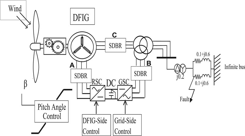
FIGURE 1. Model system.
The rotational speed [rad/s] of the wind turbine is
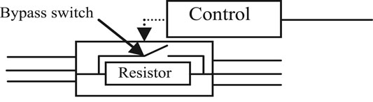
FIGURE 2. SDBR control strategy.
Variable Speed Drive Control
Figure 3 shows the control strategy of the DFIG-based variable speed wind turbine. The cost of the crowbar protection scheme used in a conventional DFIG system is more than the other schemes, such as the braking resistor or DC chopper. During grid fault, the crowbar makes the DFIG-based variable speed wind generator act like a fixed speed wind generator. This is done by disconnecting the wind generator’s rotor side converter. In this paper, the DC-link (chopper) scheme is the alternative employed in place of the traditional crowbar switch, as shown in Figure 3. The coordinated controls of the active and reactive power of the DFIG system via abc to dq and dq to abc conversion to generate pulses for the switching of the PWM are shown in Figure 3.
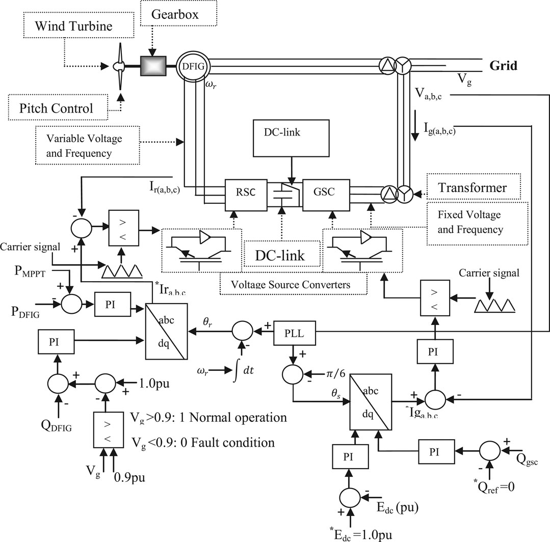
FIGURE 3. DFIG control strategy.
The new PLL control strategy used in this study has a delay element incorporated to improve the performance of the DFIG system. The PLL scheme is designed based on a frequency of 50 Hz and rated a line-to-line voltage of 0.69 kV. Unlike the conventional PLL scheme, the proposed PLL scheme in this work links the Sine and Cosine function angles for the three phases via a multiplier before the insertion of a delay element in order to boost its synchronizing strength with the grid for better performance during transient conditions.
Figure 4 shows the conventional three-phase PLL scheme, which is basically an error signal feedback system based on the principle of a synchronous rotating frame, with low pass filters and a voltage-controlled oscillator (Justo et al., 2015). The working principle is based on the conversion of measured voltage of a three-phase system to d-q component via conversion coordinates and set DC voltage reference of q-axis vref. Figure 5 shows the vector partition diagram for the PLL. From Figure 5, the d-axis component is fully co-phased with the vector voltage when the q-axis component is zero, despite the values of the voltages on the various q-axes. The PI controller in Figure 4 helps in obtaining the frequency of the system. With the grid voltage having only positive sequence fundamental components, the d-q steady value coordinate is the DC current, and its phase and frequency can be locked by controlling the q-axis component to zero. Frequency detection when the grid voltage is balanced is achieved for the conventional three-phase PLL based on tracking the grid voltage positive sequence fundamental components, as the inner of the PLL is a closed loop controller. However, during transient conditions, there will be a sudden change giving rise to an instantaneous negative sequence and zero sequence fundamental components which leads to the oscillation of the PLL output angle.
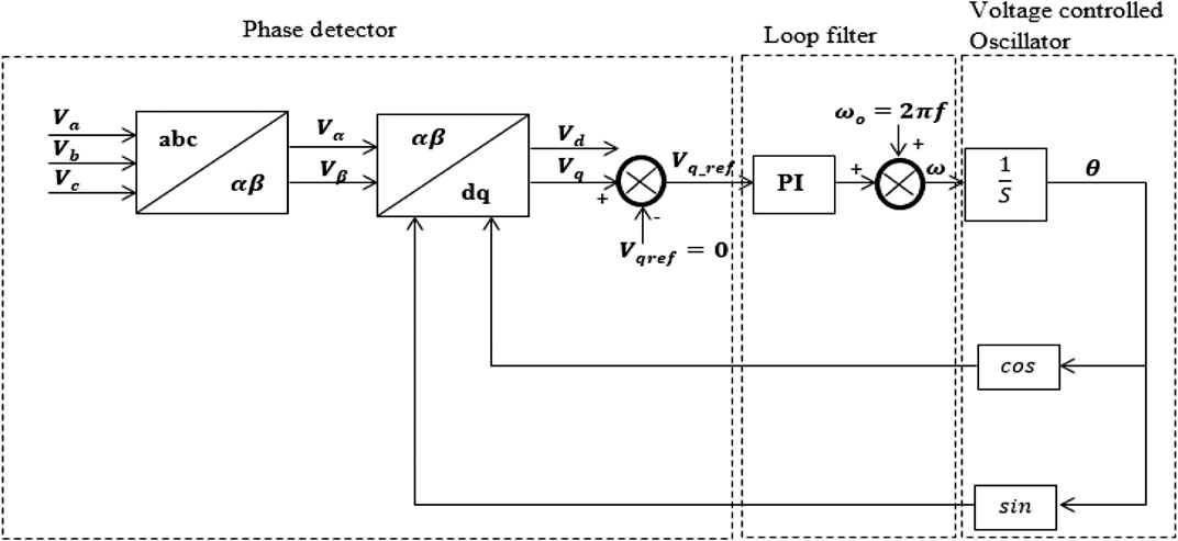
FIGURE 4. Conventional PLL scheme.
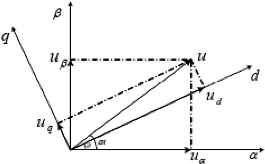
FIGURE 5. PLL vector partition.
If the grid voltage becomes unbalanced, there exists positive, negative, and zero sequence fundamental components. For a typical three-phase system without a neutral point, the zero sequence is not usually considered. Thus, the grid voltage can be expressed as (You-wei et al., 2012).
From Eq.7, V+, V− gives the voltage amplitude separately for the positive and negative sequences, respectively.
In the static αβ coordinates of the grid voltage, the fundamental positive and negative sequence component is given as:
After d-q transformation to the synchronous coordinate system, the following equation is obtained:
Considering Eqs 11, 12 leads to
The effective working of the PLL requires that ωt ≈ θ, so Eq.13 can be expressed as
From Eq.14, it could be observed that a synchronous sequence due to the positive system coordinates enables the conversion to DC components from the positive sequence, and for the components of the negative sequence, a value that is twice the frequency component is obtainable. This is because the traditional PI controller can only be used to remove the steady state error, thus the negative voltage will have influence on the output of the PLL.
The traditional PLL strategy has a negative sequence component during transient conditions in the grid. Therefore, a low loop filter cutoff frequency is required to help achieve an improved performance of the system during steady state. Based on this, since the transient performance of the system would also be affected, this study aims to propose a new configuration and control topology of PLL with a delay element as shown in Figure 6, in order to overcome this drawback. The negative effects due to the component of the voltage sequence would be greatly mitigated during transient conditions in the grid with the help of the delay element e−sT.
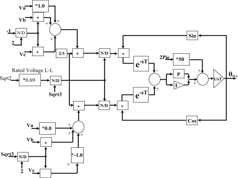
FIGURE 6. Proposed PLL scheme.
The principle of the delay element is based on phase shifting after abc/dq transformation in the controller, as shown in Figure 6, compared to the traditional strategy employed for the PLL in Figure 4. The proposed control PLL scheme would counteract twice the amount of grid frequency disturbances based on Eq.15.
DFIG Neutral Point Clamped Multilevel Converter Topology
Figure 7 shows the model system for the DFIG wind generator NPC MLC topology. The NPC has three legs, A, B, and C, with three different voltage states. Switch 1 and 3 are complementary on each leg, therefore, when switch 1 is on, switch 3 is off, and vice versa. Similarly, switch 2 and 4 are complementary. From Figure 7, each of the capacitors has a constant voltage of 0.5 Vdc, therefore having the two upper switches on will lead to an output voltage of Vdc compared to 0 level. Also, switch 2 and 3 being on will lead to 0.5 Vdc and having the two lower switches on leads to an output voltage level of 0. There exists a forbidden state whose scenario is when the first switch is on and the second is off, in addition to the three states. Table 1 shows the bridge leg voltages at different combinations of the switch states. The excitation parameters of the DC circuitry and the DFIG wind generator parameters are given in (Takahashi et al., 2006).
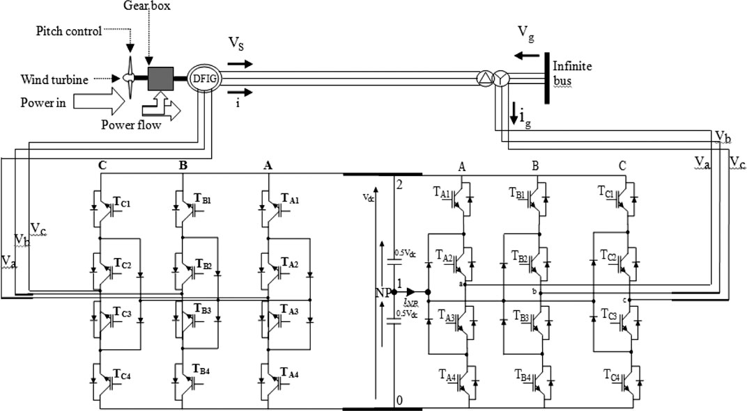
FIGURE 7. DFIG model system with NPC MLC scheme.

TABLE 1. DFIG NPC MLC bridge leg voltages for different combinations of switches .
DFIG Parallel Interleaved Multilevel Converter Topology
Figure 8 shows the model system for the DFIG wind generator Parallel Interleaved MLC topology (Okedu, 2016). Figure 9 shows the table of switching, with the switching sequence of the pulse width modulation represented by the numbers. The space vector reference Vref is formulated based on the nearest three voltage vector summation geometries in region 1, as shown in Figure 10. The connections of the passive filters of the grid side to the parallel interleaved MLC are shown in the model system. The reduction of the harmonics is achieved by the grid filters with a value of 9.6 mH and also with the help of the common mode inductor. The IGBTs are numbered for both RSC and GSC power converters.
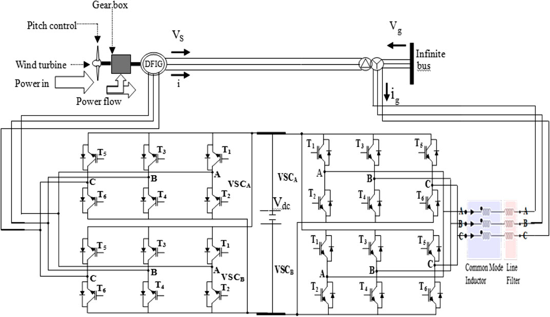
FIGURE 8. DFIG model system with parallel interleaved MLC scheme.
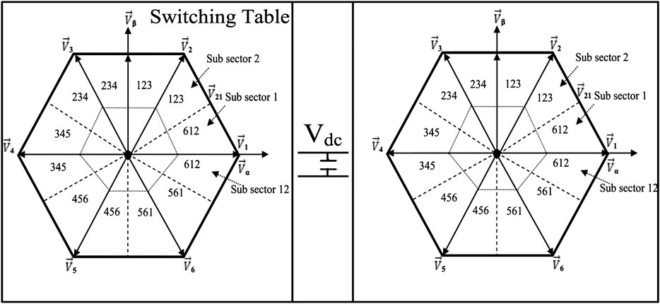
FIGURE 9. Switching table for the parallel interleaved MLC scheme.
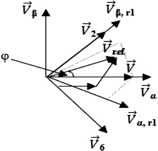
FIGURE 10. Reference voltage SV formation for parallel interleave MLC scheme.
For the operation of the two-level conventional SV modulation, the converters cycle through switching cycles with four switch states. However, for the 180° parallel interleaved MLC scheme, its SV modulation gives voltage and the common mode changes with a peak value to
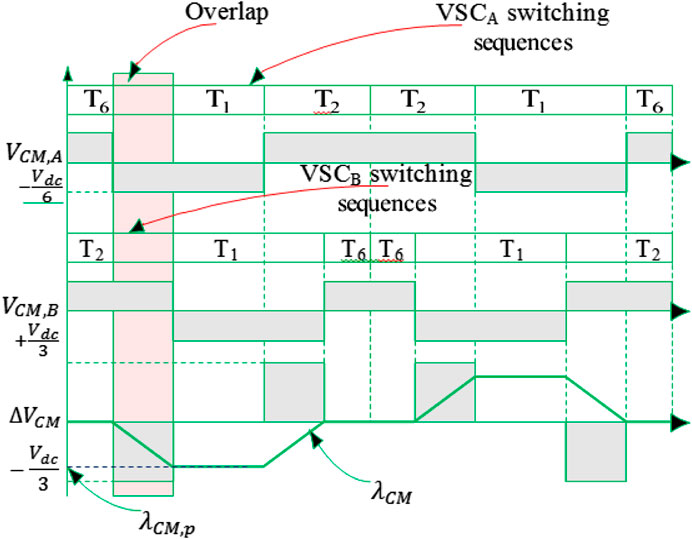
FIGURE 11. Switching sequence for parallel interleave MLC scheme.
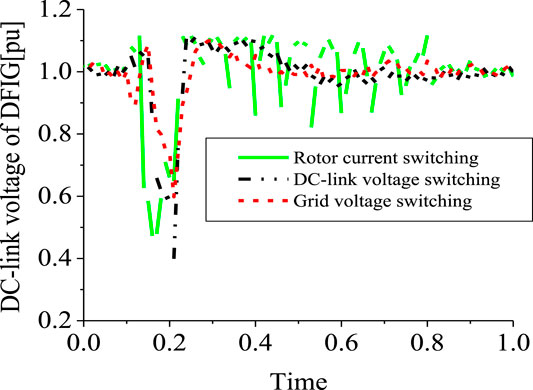
FIGURE 12. DC-link voltage of DFIG.
The active vectors
The DFIG parallel interleaved MLC switching sequence and common mode (CM) voltages are shown in Figure 13 for both converter sides. The two converter halves are tagged A and B, respectively. With a voltage common to each voltage source converter, the maximum individual VSCs’ common mode voltage is constrained to
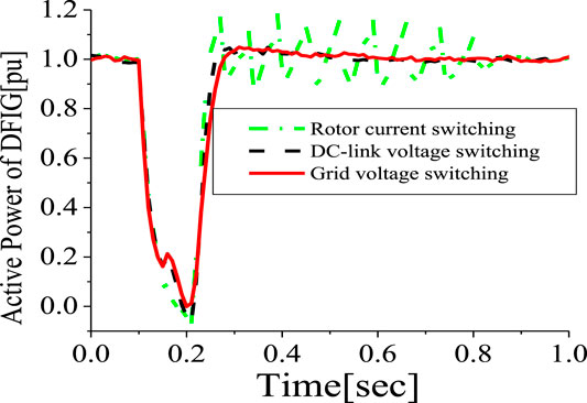
FIGURE 13. Active power of DFIG.
Simulation Results and Discussions
SDBR Switching and Position
Simulations were done based on the optimal switching signal (Figure 2) and placement (Figure1) of SDBR with a value 0.01 pu for a severe 3LG fault, which occurs at 0.1 s. The two-level inverter scheme with a DC chopper was used in this investigation. As seen from Figures 12–14, the following wind generator variables—DC-link voltage, active power, and reactive power—show improved performances with low distortions, with the use of the braking resistor, when subjected to transient conditions. This was mainly due to the fact that most of the harmonics and vibrations experienced during the transient period were transferred by the rotor current and DC-link voltage signals to the braking resistor circuitry, compared to when the grid voltage signal was employed. The scenario where the braking resistor was inserted at the stator side of the wind generator, considering the grid voltage switching signal, led to an enhanced performance of the terminal voltage and rotor speed variables of the wind generator (Figures 15, 16). The reason for this is because the wind generator active power was enhanced, and consequently, its stability was improved. The braking resistor also limits the rotor speed at times of transient changes, thus improving the power output of the wind turbine. Consequently, the recovery of the variables of the wind generator after fault is better because of the control capability of the braking resistor in the acceleration of the rotor speed.
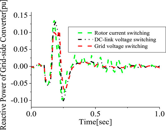
FIGURE 14. Grid side reactive power of DFIG.
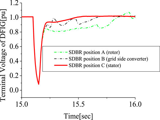
FIGURE 15. Terminal voltage of DFIG.
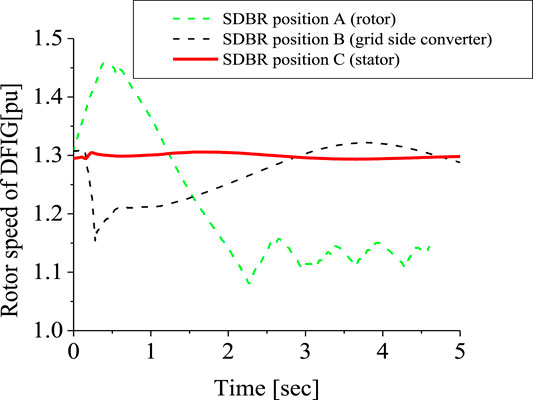
FIGURE 16. Rotor speed of DFIG.
2-Level Interleave Inverter and SDBR
A comparison was made between the single 2-level converter system and when it is interleaved for the wind turbine system. As seen from Figures 17, 18 for the DC-link voltage and reactive power of the wind generator, interleaving the two side converters using the 2-level converters enhances the stability of the wind turbine during transient changes by providing more reactive power within the DFIG power converters (Figure 18). Based on the best SDBR performance for the stator side, as given in section SDBR Switching and Position of the simulation results, a further investigation was carried out for the 2-level interleave inverter system to improve the stability of the wind turbine for the DC-link voltage and the rotor speed variables, shown in Figures 19, 20, respectively. The DC-link charging current of the capacitor is mitigated during fault scenario in order to avoid the under-or over-voltage experienced, as shown in Figure 19. In addition, this topology effectively controls the voltage and current in the rotor circuitry. This would definitely improve the rotor speed of the DFIG as shown in Figure 20.
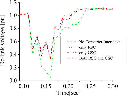
FIGURE 17. DC-link voltage of DFIG.
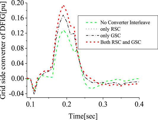
FIGURE 18. Grid side converter of DFIG.
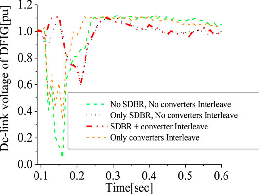
FIGURE 19. DC-link voltage of DFIG.
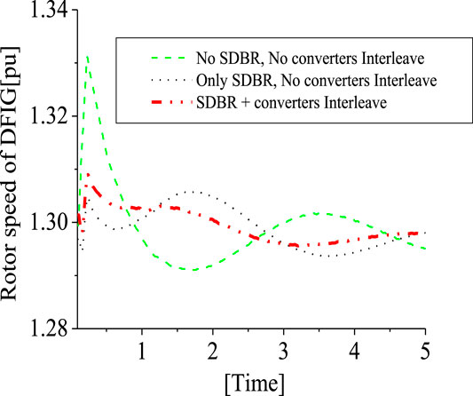
FIGURE 20. Rotor speed of DFIG.
3-Level Inverter, 2-Level Interleave Inverter, and SDBR
Investigation was further carried out comparing the responses of the 3-level inverter and the 2 level interleave inverter. The responses of the DFIG DC-link voltage and active power in Figures 21, 22, respectively, is better for the 2-level interleave inverter than the 3-level inverter due to more reactive power being supplied, as shown in Figure 23. However, the response of the rotor current is almost the same, but in different directions, as shown in Figure 24, for both converter systems. An addition of SDBR to both systems, as shown in Figures 25–28, shows that the SDBR can further enhance the performance of both inverter schemes for the DC-link voltage, real power, reactive power of the grid side converter, and rotor speed of the wind generator. The response of the 2-level interleave inverter is slightly better because the SDBR more greatly limits the reactive power (Figure 27) for the 3-level inverter.
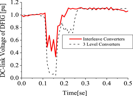
FIGURE 21. DC-link voltage of DFIG.
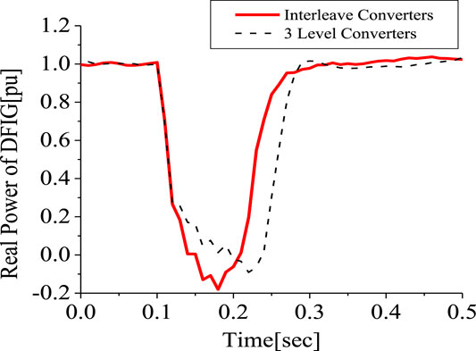
FIGURE 22. Real power of DFIG.
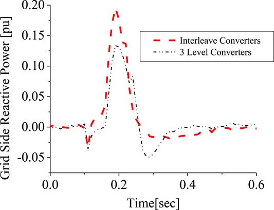
FIGURE 23. Grid side converter of DFIG.
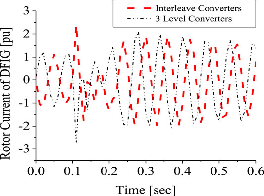
FIGURE 24. Rotor current of DFIG.
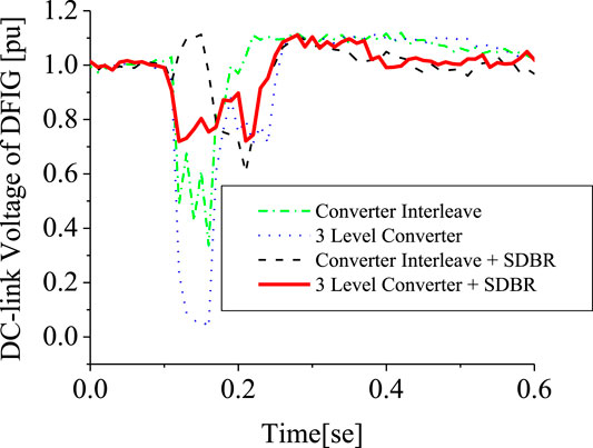
FIGURE 25. DC-link voltage of DFIG.
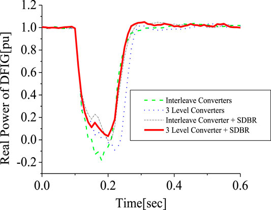
FIGURE 26. Real power of DFIG.
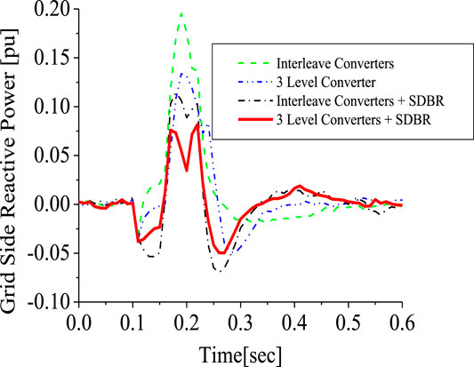
FIGURE 27. Grid side converter of DFIG.
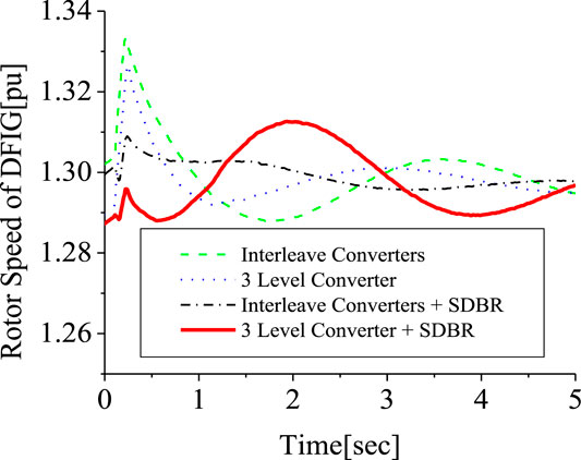
FIGURE 28. Rotor speed of DFIG.
Proposed PLL Control Strategy and the Various Schemes
The conventional PLL has been used in the earlier analysis. This section investigates five schemes. Scheme 1 is the 2-level converter (2LC) using the conventional PLL, scheme 2 is the 2LC with the proposed PLL scheme in Figure 6, scheme 3 is the 2LC with a proposed PLL scheme and SDBR. Schemes 4, 5 uses the 3-level converter (3LC), and parallel Interleave converter (IC), having the proposed PLL scheme and SDBR, respectively. Figure 29 shows the response of the DFIG wind turbine DC-link voltage considering the various converter schemes without SDBR. The response of the DC-link voltage using the proposed PLL scheme for the 2-level converter system is better than when the conventional PLL scheme was used. This is because the proposed PLL scheme helps in enhancing the reactive power of the DFIG grid side converter (Figure 30). The coordinated control of SDBR with the proposed scheme shows that a better performance of the wind turbine variables could be achieved during transient changes for the DC-link, real power, and rotor speed of the wind generator as shown in Figures 31–33. In Figure 31, the SDBR and the proposed PLL scheme enhances the single step 2-level inverter, thus giving a better response than the interleaved and 3-level inverter schemes. This is also the same for the wind turbine real power in Figure 32 and rotor speed in Figure 33, respectively.
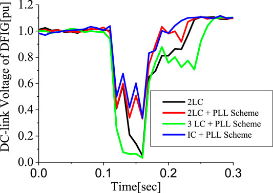
FIGURE 29. DC-link voltage of DFIG.
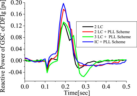
FIGURE 30. Reactive power of DFIG.
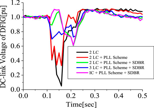
FIGURE 31. DC-link voltage of DFIG.
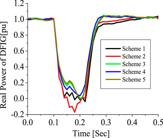
FIGURE 32. Real power of DFIG.
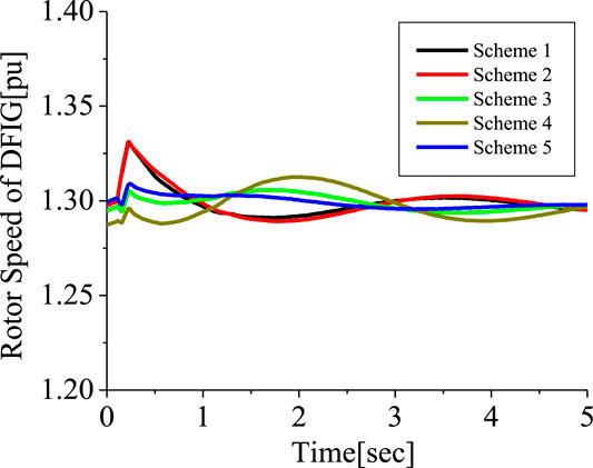
FIGURE 33. Rotor speed of DFIG.
Conclusion
In this paper, the DFIG variable speed wind turbine performance operating with three types of inverter system has been investigated. The 2 level single step inverters, 2 level parallel interleaved inverters, and 3 level inverter systems for a DFIG wind turbine during transient changes were presented. An SDBR was used to enhance the performances of all the inverter systems.
Furthermore, a Phase Lock Loop (PLL) was proposed in conjunction with the SDBR system to improve the performance of the wind turbine using a 2-level single step inverter system. It was observed that the proposed PLL SDBR strategy can further improve the performance of the 2-level single step inverter system during transient changes, thus enhancing the transient responses of the wind turbine.
Data Availability Statement
The original contributions presented in the study are included in the article/Supplementary Material, further inquiries can be directed to the corresponding author.
Author Contributions
KO did the conception, simulations and design of the controllers in the work. HB did the literature review and sponsorship of the work.
Funding
Funding from Research seed of German University, Oman.
Conflict of Interest
The authors declare that the research was conducted in the absence of any commercial or financial relationships that could be construed as a potential conflict of interest.
References
Asiminoaci, L., Aeloiza, E., Enjeti, P. N., and Blaabjerg, F. (2008). Shunt active-power filter toplogy based on parallel interleaved inverters. IEEE Trans. Ind. Electron. 55 (3), 1175–1189. doi:10.1109/tie.2007.907671
Baiju, M. R., Gopakumar, K., Umanand, L., and Pittet, A. (2002). “Multi axis space phasor based multi-level current hysteresis controller for an open end winding induction motor fed from dual inverters,” Proceedings of the 29th european conference on intelligent motion (PCIM), Germany, May, 2002 (Germany: Nurnberg), 405–410.
Bansal, R. C., Bhatti, T. S., and Kothari, D. P. (2003). Bibliography on the application generators in non- conventional energy systems. IEEE Trans. Energy Convers. 18 (3), 433–439. doi:10.1109/tec.2003.815856
Brod, D. M., and Novotny, D. W. (1985). Current control of VSI-PWM inverter. IEEE Trans. Ind. Appl. 21 (4), 562–570. doi:10.1109/tia.1985.349711
Buso, S., Malesani, L., and Mattavelli, P. (1998). Comparison of current control techniques for active filter applications. IEEE Trans. Ind. Electron. 45 (5), 722–729. doi:10.1109/41.720328
Chen, L., Deng, C., Zheng, F., Li, S., Liu, Y., and Liao, Y., (2015). Fault ride-through capability enhancement of DFIG-based wind turbine with a flux-coupling-type SFCL employed at different locations. IEEE Trans. Appl. Supercond. 25 (3), 1–5. doi:10.1109/tasc.2014.2373511
Da Silva, J. L., de Oliveira, R. G., Silva, S. R., Rabelo, B., and Hofmann, W. (2008). “A discussion about a start-up procedure of a doubly-fed induction generator system,” Nordic workshop on power and industrial electronics, Espoo, Finland, June 9, 2008–June 11, 2008 (Norway: NORPIE), 8.
Djeriri, Y., Meroufel, A., Belabbes, B., and Massoum, A. (2013). Three-level NPC voltage source converter based direct power control of the doubly fed induction generator at low constant switching frequency. Revue des Energies Renouvalables 16 (1), 91–103. doi:10.1109/tie.2008.2007829
Firouzi, M., and Gharehpetian, G. B. (2018). LVRT performance enhancement of DFIG-based wind farms by capacitive bridge-type fault current limiter. IEEE Transactions on Sustainable Energy 9 (3), 1118–1125. doi:10.1109/tste.2017.2771321
Ghennam, T., Berkouk, E. M., and Francois, B. (2013). A vector hysteresis current control applied on three level inverter-application to the active and reactive power control of doubly fed induction generator based wind turbine. Int. Rev. Econ. Educ. 6 (1), 27. doi:10.1109/icoei.2018.8553761
Gohil, G., Bede, L., Teodorescu, R., Kerekes, T., and Blaabjerg, F. (2015). An integrated inductor for parallel interleaved VSCs and PWM schemes for flux minimization. IEEE Trans. Ind. Electron. 62 (12), 7534–7546. doi:10.1109/tie.2015.2455059
Jung-Woo, P., Ki-Wook, L., Dong-Wook, K., Kwang-Soo, L., and Jin-Soon, P. (2007). “Control method of a doubly-fed induction generator with a grid synchronization against parameter variation and encoder position,” Industry applications conference, 2007, 42nd IAS annual meeting, conference record of 2007 IEEE, New Orleans, LA, September 23, 2007–September 27, 2007. New Orleans, LA: IEEE, 931–935.
Justo, J. J., Mwasilu, F., and Jung, J. W. (2015). Doubly fed induction generator based wind turbines: a comprehensive review of fault ride through strategies. Renew. Sustain. Energy Rev. 45 (C), 447–467. doi:10.1016/j.rser.2015.01.064
Kazmierkoswki, M. P., and Malesani, L. (1998). Current control techniques for three phase voltage source PWM converters: a survey. IEEE Trans. Ind. Electron. 45 (5), 691–703. doi:10.1109/41.720325
Kwon, B. H., Kim, T. W., and Youm, J. H. (1998). Novel SVM-based hysteresis current controller. IEEE Trans. Power Electron. 13 (2), 297–307.
Ma, K., Zhou, D., and Blaabjerg, F. (2015). Evaluation and design tools for the reliability of wind power converter system. Journal of Power Electronics 15 (5), 1149–1157. doi:10.6113/jpe.2015.15.5.1149
Muller, S., Deicke, M., and Doncker, R. W. D. (2002). Doubly fed induction generator systems for wind turbine. IEEE Ind. Appl. Mag. 8 (3), 26–33. doi:10.1109/2943.999610
Murphy, J., and Turnbull, F. (1988). Power electronics control of AC motors. New York, NY: Pergamon.
Nabae, A., Takahashi, I., and Akagi, H. (1981). A new neutral point clamped PWM inverter. IEEE Trans. Ind. Appl. 17, 518–523. doi:10.1109/tia.1981.4503992
Nagay, I., Suto, Z., and Backhausz, L. (1996). “Periodic states of hysteresis current control of induction motor,” Proceedings of the 9th european conference on intelligent motion (PCIM). Germany: Nurnberg), 605–619.
Nagy, I. (1994). Novel adaptive tolerance band based PWM for field oriented control of induction machines. IEEE Trans. Ind. Electron. 41 (4), 406–417.
Nashed, M. N., and Eskander, M. N. (2012). Comparing the quality of power generated from DFIG with different types of rotor converters. J. Electromagn. Anal. Appl. 4, 21–29. doi:10.4236/jemaa.2012.41004
Ohi, T., Iwata, A., and Arai, K. (2002). “Investigation of gate voltage oscillations in IGBT module under short circuit conditions,” Proceedings of 33rd annual power electronics specialist conference, Queensland, Australia, June 23, 2002–June 27, 2002, 4, 1758–1763.
Okedu, K. E. (2013). Hybrid control strategy for variable speed wind turbine power converters. Int. J. Renew. Energy Resour. 3 (2), 283–288. doi:10.1063/9780735422292_005
Okedu, K. E. (2016). Enhancing DFIG wind turbine during three-phase fault using parallel interleaved converters and dynamic resistor. IET Renew. Power Gener. 10 (6), 1211–1219. doi:10.1049/iet-rpg.2015.0607
Okedu, K. E. (2019). Enhancing the performance of DFIG variable speed wind turbine using parallel integrated capacitor and modified modulated braking resistor. IET Gener., Transm. Distrib. 13 (15), 3378–3387. doi:10.1049/iet-gtd.2019.0206
Okedu, K. E. (2020). Improving the transient performance of DFIG wind turbine using pitch angle controller low pass filter timing and network side connected damper circuitry”, IET Renew. Power Gener. 14 (7), 1219–1227. doi:10.1049/iet-rpg.2019.1124
Okedu, K. E., and Muyeen, S. M. (2011). “Improvement of fault ride through capability of wind farm using DFIG considering SDBR,” 14th European Conference of Power Electronics EPE, Birmingham, United Kingdom, August, 2011. Editors Rion Takahashi, and Junji Tamura (Birmingham, United Kingdom: EPE), 1–10.
Okedu, K. E., Muyeen, S. M., Takahashi, R., and Tamura, J. (2012). Wind farms fault ride through using DFIG with new protection scheme. IEEE Trans. Sustain. Energy 3 (2), 242–254. doi:10.1109/tste.2011.2175756
Rashid, G., and Ali, M. H. (2016). Nonlinear control-based modified BFCL for LVRT capacity enhancement of DFIG based wind farm. IEEE Trans. Energy Convers. 99, 284–295. doi:10.1109/TEC.2016.2603967
Reigosa, P. D., Wu, R., Iannuzzo, F., and Blaabjerg, F. (2015). Robustness of MW level IGBT modules against gate oscillations under short circuit events. Microelectron. Reliab. 55, 1950–1955. doi:10.1016/j.microrel.2015.07.011
Salama, S., and Lennon, S. (1991). “Overshoot and limit cycle free current control method for PWM inverters,” Proceeding of european conference on power electronics and applications (EPE), Firenze, Italy, September 3–6, 1991, 3, 247–251.
Stemmler, H., and Geggenbach, P. (1993). Configurations of high power voltage source inverter drives,” Proceedings of the 5th european conference on power electronics and applications Brighton, United Kingdom, September 13–16, 1993, 5, 7–12.
Tekwani, P. N., Kanchan, R. S., and Gopakumar, K. (2005). Current-error space vector based hysteresis PWM controller for three-level voltage source inverter fed drives. IEE Proc. Elec. Power Appl. 152 (5), 1283. doi:10.1049/ip-epa:20050109
Takahashi, R., Tamura, J., Futami, M., Kimura, M., and Idle, K. (2006). A new control method for wind energy conversion system using doubly fed synchronous generators. IEEJ Trans. Power and Energy 126 (2), 225–235. doi:10.1541/ieejpes.126.225
Ueda, F., Matsui, K., Asao, M., and Tsuboi, K. (1995). Parallel-connections of pulse width modulated inverters using current sharing reactors. IEEE Trans. Power Electron. 10 (6), 673–679
Volke, A., and Hornkamp, M. (2012). IGBT modules-technologies, driver and applications. Second Edition. AG: Infineon Technologies.
Wang, H., Liserre, M., and Blaabjergy, F. (2013). Toward reliable power electronics-challenges, design tools and opportunities. IEEE Industrial Electronics Magazine 7 (2), 17–26. doi:10.1109/mie.2013.2252958
Xu, L., and Cartwright, P. (2006). Direct active and reactive power control of DFIG for wind energy generation. IEEE Trans. Energy Convers. 21 (3), 750–758. doi:10.1109/tec.2006.875472
You-wei, L., Zhi-hui, C., and Juan, S. (2012). Application of PLL in the generator side converter for doubly fed wind power generation systems. Energy Procedia 16, 1822–1830. doi:10.1016/j.egypro.2012.01.280
Keywords: index terms-doubly fed induction generator, series dynamic braking resistor, wind energy, power converters, stability, protection schemes
Citation: Okedu KE and Barghash HFA (2021) Investigating Variable Speed Wind Turbine Transient Performance Considering Different Inverter Schemes and SDBR. Front. Energy Res. 8:604338. doi: 10.3389/fenrg.2020.604338
Received: 09 September 2020; Accepted: 03 December 2020;
Published: 19 January 2021.
Edited by:
Alexis B. Rey-Boué, Universidad Politécnica de Cartagena, SpainCopyright © 2021 Okedu and Barghash. This is an open-access article distributed under the terms of the Creative Commons Attribution License (CC BY). The use, distribution or reproduction in other forums is permitted, provided the original author(s) and the copyright owner(s) are credited and that the original publication in this journal is cited, in accordance with accepted academic practice. No use, distribution or reproduction is permitted which does not comply with these terms.
*Correspondence: Kenneth E. Okedu, kenokedu@yahoo.com, okedukenneth@nu.edu.om