A Construction Method of Lower Limb Rehabilitation Robot with Remote Control System


School of Mechatronical Engineering, Beijing Institute of Technology, Beijing 100081, China
*
Authors to whom correspondence should be addressed.
Appl. Sci. 2021, 11(2), 867; https://doi.org/10.3390/app11020867
Submission received: 22 December 2020
/
Revised: 13 January 2021
/
Accepted: 18 January 2021
/
Published: 19 January 2021
(This article belongs to the Special Issue Tele-Rehabilitation Robotics)
Abstract
:In response to the rehabilitation needs of stroke patients who are unable to benefit from conventional rehabilitation due to the COVID-19 epidemic, this paper designs a robot that combines on-site and telerehabilitation. The objective is to assist the patient in walking. We design the electromechanical system with a gantry mechanism, body-weight support system, information feedback system, and man-machine interactive control system. The proposed rehabilitation robot remote system is based on the client/server (C/S) network framework to realize the remote control of the robot state logic and the transmission of patient training data. Based on the proposed system, doctors can set or adjust the training modes and control the parameters of the robot and guide remote patient rehabilitation training through video communication. The robotic system can further store and manage the rehabilitation data of the patient during training. Experiments show the human-computer interaction system of the lower limb rehabilitation robot has good performance, can accurately recognize the information of human motion posture, and achieve the goal of actively the following motion. Experiments confirm the feasibility of the proposed design, the information management of stroke patients, and the efficiency of rehabilitation training. The proposed system can reduce the workload of the doctors in practical training.
1. Introduction
For post-stroke patients, rehabilitation of the hemiplegic part of the brain is the main medical treatment, and early rehabilitation helps to reduce the possibility of future disabilities. Traditional rehabilitation training requires the therapist to assist the patients in manual rehabilitation. This rehabilitation method is time-consuming and costly. Nevertheless, due to the lack of objective data for the scientific evaluation of the training parameters and rehabilitation effects, it is difficult to optimize the training parameters to obtain the best therapeutic effect. Recent advances in medical technology have improved the survival rate of stroke patients and expanded the number of hemiplegic patients. Therefore, the rehabilitation of stroke patients has become essential. In 2020, the epidemic caused by the COVID-19 virus spread around the world. Hence, going to a hospital or rehabilitation institution for traditional rehabilitation is not the best choice. The question is what should patients do at home to recover? Telemedicine is of essential importance in meeting the rehabilitation needs of home-bound patients and improving the quality of medical care. Telerehabilitation refers to the application of Internet and communication technologies to transmit electronic rehabilitation data to different places. This provides several advantages of including convenience and speed, and it is also available at any time and any place. Telerehabilitation also facilitates completing rehabilitation training at home. Comparing to on-site rehabilitation, telerehabilitation has different rehabilitation environments, different rehabilitation equipment, different rehabilitation procedures, guidance methods, guidance objects, etc. Telerehabilitation also provides advantages including high efficiency, convenience, lower costs, and practicality. No matter where you are, in a remote outlying town or near a city, you can enjoy the same quality of telerehabilitation services.
Instead of a regular rehabilitation center or hospital, most older people need daily telerehabilitation in their living environment. The existing techniques and technologies and challenges to promote and improve the effectiveness of telerehabilitation are discussed in [1]. In [1] the technological solutions based on video analytics, wearables, robotic support, sensor, and gamified telerehabilitation are examined. It also analyzes and discusses the current strengths, limitations, and future challenges of telerehabilitation medicine. Further, [2] suggests that sending remote rehabilitation services to patients’ homes is useful to patients’ recovery. Telerehabilitation services can overcome geographical, physical, and cognitive barriers and enable doctors to watch, educate, and treat patients in their environment, improving, or even replacing traditional forms of rehabilitation. Setting up a telerehabilitation system needs extensive study. For instance, [3] suggests that telemedicine and telecommunication are no longer simply remote connections. Such systems can capture and summarize data and provide information to patients, care, or healthcare professionals. The corresponding data can be also stored locally or in a shared environment, e.g., cloud. The current telemedicine and remote watching are trying to establish an efficient and sustainable system to collect and analyze data. Although progress has been made in remote home rehabilitation, there are still several major obstacles. The authors of [4] show that telerehabilitation is an effective intervention in treating stroke patients. Patients can undergo various forms of therapy under the remote supervision of a doctor to improve the motor and cognitive impacts caused by the stroke. Research has also shown that telerehabilitation interventions have better or equal efficacy for motor, cortical, and mood disorders compared to traditional face-to-face therapy. Furthermore, [5] examines the perceived barriers and facilitators of telerehabilitation (TR) for stroke patients, caregivers, and rehabilitation therapists in Asia. It suggests that patient attributes and context are significant determinants in the adoption and compliance of stroke patients to technology-driven interventions like TR. The work in [5] further proposes to create awareness and understanding of telerehabilitation among older patients in a variety of ways. Moreover, [6] proposes action observation therapy for children with cerebral palsy based on a telerehabilitation environment. Additionally, [7] designs a telerehabilitation robot that can be used at home by stroke patients. The robot supports three-dimensional rehabilitation and its adaptive controller optimizes the whole process. The designed robot in [7] further undergoes initial usability testing to develop it into a rehabilitation system for home use. The needs of older adults and caregivers related to their mobility needs and the technical requirements of assistive robots are investigated in [8].
The analysis in [8] indicates four categories of needs from the perspective of the elderly individual and three categories from the caregivers’ viewpoints. Mobility functions of the robot are investigated to improve the wellbeing of the elderly. In [9], the authors evaluated a home-based telerehabilitation system in patients with chronic hemiparetic stroke. After a period of clinical trials, this home-based system was shown to be effective in providing telerehabilitation, education, and secondary stroke prevention to participants. Hocoma company has also developed a lower limb rehabilitation robot called Andago, which can realize ground-bearing movement training. Further in [10,11] the usability of the Andago and its acceptance by patients and therapists were investigated. It was further shown that Andago can be used safely under therapeutic supervision for overground gait training in stroke patients presenting moderate to severe gait disorders. Additionally, [12] proposes to build asynchronous training and treatment framework in a multilateral telerehabilitation system. It is also shown that increasing the number of collaborative working robots during telerehabilitation enables meeting the goals of simultaneous treatment and training. It is also discussed in [13] that there is a great potential for wearable ankle robots in telerehabilitation. The work in [13] discusses the design of the rehabilitation robot, human-computer interaction, logic controller, visual-haptic contact design, web-based communication between the user and the remote therapist, and user-friendly. The designed software in [13] consists of three parts: patient database, graphic user interface, and virtual reality practice library. The work in [14] also introduces a single-degree-of-freedom rehabilitation robot and a new telerehabilitation robot system. Doctors can use the remote control system to conduct video communication with patients, set the training mode, and control the parameters of the robot. The remote rehabilitation robot also collects data from the patient’s training process through sensors. Research shows that the telerehabilitation robot system has good reliability. It can improve the efficiency of rehabilitation training and address shortages of medics. Robots can also improve the effectiveness of assisted rehabilitation by motivating patients to participate.
The work in [15] presents a game-based telerehabilitation system that combines a graphical user interface and a robotic arm to enable interaction between doctor and patient. The experimental results and participant feedback indicate that the telerehabilitation system can solve the rehabilitation needs of specific patients and help doctors in evaluating the rehabilitation progress of patients. The telerehabilitation system can also reduce medical costs and at the same time improve the quality of life of the rehabilitation users. Further in [16], a variety of assistive service robots are developed for the elderly and vulnerable populations. Such robots address the loneliness of the elderly through communications and interactions. Additionally, they have significant advantages in data collection to assess the health status of the elderly. The humanized design of robots provides a better affinity for humans and can be more easily integrated into the daily life of patients in the home or hospital environments. Furthermore, combined with interactive entertainment, such robots can effectively prevent dementia and the phenomenon of declining ability in daily life activities for rehabilitation training of lower limb limbs for hemiplegic patients. This can also restore the motor function of lower limbs and achieve self-care in daily life and returning to normal life, whereas assistive service robots are not sufficient for these purposes.
However, these robots have some limitations. For example, exoskeleton walking rehabilitation robots based on treadmills are bulky and heavy. Furthermore, their dynamic models are more complicated, and because the motors are often installed at joints, it is difficult for patients to control the movements. In this paper, our objective is to address the issue with the complex structure and fixed use of lower limb rehabilitation robots. We propose a human lower limb rehabilitation robot that provides bodyweight balance support and mobility for patients. Our lower limb rehabilitation robot achieves self-weight loss and balance, and mobile patient companion for stroke patients. Moreover, we develop a new interactive system for remote lower limb rehabilitation robots. The designed system interface includes robotic rehabilitation parameters, patient information material, video screens, and database management. The system allows doctors to coach and supervise stroke patients in telerehabilitation exercises. This also enables the medics to analyze rehabilitation data, with the aim of objectively and quantitatively assessing the effectiveness of the patient’s rehabilitation. The system consists of a server computer connected to the network for the doctor, and a client computer connected to the rehabilitation robot and the network. The network acts as a data transmission channel between the server computer and the client computer.
This paper is organized as follows: In Section 2, the framework of the rehabilitation robot system design for the stroke patients is presented, and the construction method of the rehabilitation robot is introduced. The remote control system and its hardware, software, and telerehabilitation system design are also presented. In Section 3, the experiments with the remote control system for the rehabilitation robot are conducted and the results are discussed. Finally, the conclusions are presented in Section 4.
2. Materials and Methods
2.1. Design of Rehabilitation Robot System
2.1.1. Requirements
The lower limb rehabilitation robot provides rehabilitation training for patients with stroke or lower limb walking dysfunction. Personalized rehabilitation training can help patients to recover lower limb muscle movement function gradually and adapt to their walking. Doctors can evaluate and analyze the patients’ rehabilitation effect quantitatively and objectively using the feedback data from the robot sensor system. Patients can use lower limb rehabilitation robots to train at home or in communities, and doctors can adjust the value of the robot’s body-weight support (BWS) system to keep the patient in a balanced and upright state in order to help the patient to reduce the burden of lower limb muscle walking and gradually restore the lower limb movement strength. The force sensing system in the BWS system monitors the changes in the strength of the lower limbs during the patient’s rehabilitation training. With the improvement of the rehabilitation treatment effect, the patient’s lower limb strength increases gradually. The force sensing feedback data value in the BWS system will show a decreasing trend, meanwhile, the data can be used to evaluate the rehabilitation effect of patients’ lower limbs objectively and quantitatively. When the patient falls with insufficient lower limb strength, the force sensor data increases instantly and the emergency stop protection state of the robot is triggered so that to protect the patient injured. The robot with human-computer interaction system can company the patient to walk around in real time, this movement mode can enhance the autonomy of artificial intentions in the lower limb rehabilitation training, and improve the patient’s self-confidence and active rehabilitation willingness in the rehabilitation process. Compared with the current training robots used in-hospital rehabilitation, the robot system designed in this paper has three main functions: (1) BWS system; (2) multi-sensor information feedback system; and (3) human-computer interaction system.
2.1.2. Key Factors
At present, rehabilitation robots have some points for improvement such as large size, small quantity of products in high performance, prescribed training site, few users, and insufficient humanity design. At the same time, the patients’ rehabilitation environment is mostly indoors, they require a high flexibility of the rehabilitation robot because of the aging society. In order to make the patients have good mood to train, all components or functional units of the robot are integrated in the movable robot body, so this robot is a compact and mobile independent training platform that can be used in open and flat places such as living rooms, courtyards and parks. Patients generally have motor dysfunction and insufficient self-protection abilities. The safety protection of patients is more important and needs to be considered at every stage of robot design. Combining the above factors, under the premise of achieving the goal of patient rehabilitation training, the design of lower limb rehabilitation robots first needs to consider safety issues, followed by mechanism optimization issues. Rehabilitation robots not only meet safety requirements but also be used flexibly in the workspace. At the same time, patients of different races, heights, and ages can use this robot, its structural design can adapt to changes in users.
According to the average body size standard data of the Asian and European population [17,18,19], the body height is about 170~175 cm, the body width is about 45~55 cm, and the weight is about 60~75 kg. Some patients have insufficient lower limb strength and cannot directly use the rehabilitation robot, and need wheelchairs for assistance. The width of a wheelchair commonly used in daily life is about 70 cm. The width of a single door in public buildings is generally about 100 cm, the width of a double door is about 120~180 cm, and the height is generally not less than 200 cm. According to the international elevator industry standards, the load of the elevator is more than 1100 kg, and the standard door opening size is not less than 1100 × 2100 cm2
To meet the mobility of robots in such environments and the convenience of wheelchair patients, refer to the above data. The robot structure design has an inner dimension of 76 cm, an outer dimension of 98 cm in width, 120 cm in length, and 180 cm in height. This design ensures that the robot can move between rooms, elevators, and buildings in a public environment, and has good pass ability. Additionally, for some narrow doors that cannot be passed, the robot solves such problems through disassembly and assembly.
2.1.3. Design of Robot Mechanical and Electrical Structure
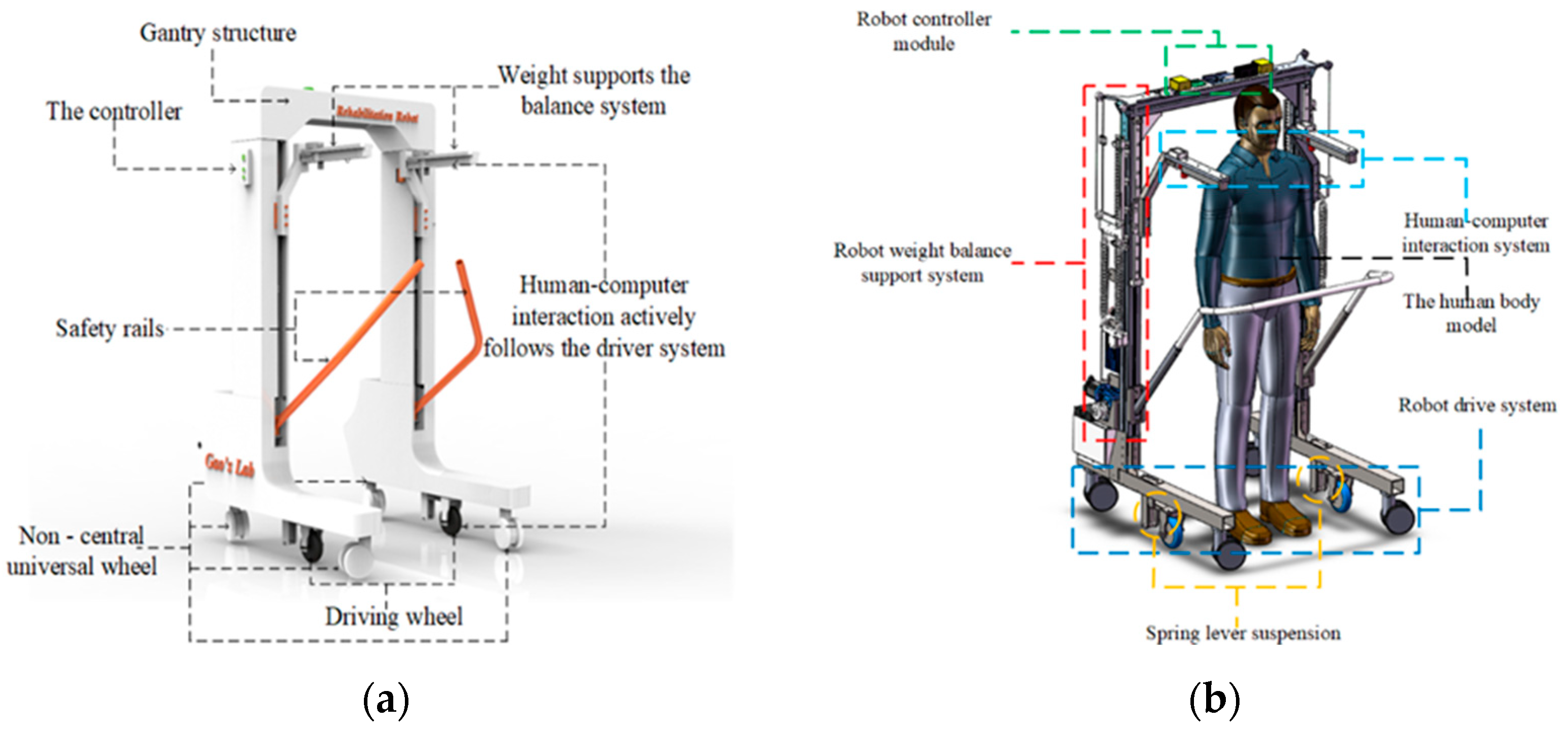
The rehabilitation robot should have the characteristics of simple structure, high equipment stability, good robustness of the control system, and compliant human-computer interaction. The robot needs to realize the integration of medicine and engineering in the design process. The rehabilitation robot platform system is shown in Figure 1a,b. The size of the robot is 120 × 98 × 180 cm3, forming an independent training space. The robot adopts a gantry scheme to facilitate the use of wheelchairs by patients. Second, the beam and column of the gantry structure are made of aluminum profiles, and the base is made of steel materials. This material choice can reduce the structure of the robot and improve the stability of the equipment. Two driving wheels are installed in the middle of the base to provide the driving force for the robot. At the same time, four non-central universal wheels are installed at the front and rear to carry the robot’s own weight and load. The robot driving wheel is installed in the middle of the base so that the robot can realize a small radius or in situ steering, and improve the mobility of the robot. The robot drive system adopts a spring lever suspension design. The compression spring provides pressure to the drive wheel through the lever, so that the drive wheel can maintain contact with the ground and ensure the continuity of power output. The driving wheel adopts a 24 V dual-shaft hub servo motor with a maximum power of 200 W and a rated output torque of 2.4 N.m. The built-in 1024-line photoelectric encoder can accurately feedback the motion data of the driving wheel and achieve closed-loop robust control.
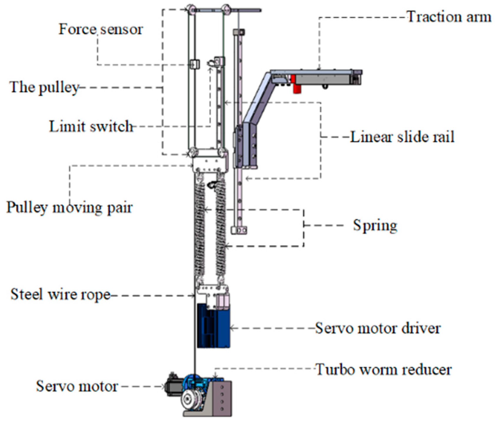
The lower limbs of stroke patients cannot provide enough strength to maintain body balance. Patients need to use the upper limbs of the healthy side to assist the body balance during exercise. Patients need to rely on external forces to maintain body balance during rehabilitation training. The robot BWS system is shown in Figure 2. The patient has unilateral rehabilitation needs on the left or right side of the body, so the BWS system adopts a left-right symmetrical structure design. The system consists of steel cable, servo motor, worm gear reducer, force sensor, fixed shaft pulley, pulley moving pair, tension spring, linear guide, and traction arm. To make the system compact and to ensure sufficient output, the robot is equipped with a 1:40 worm gear reducer, which can provide a support force of 2500 N for the patient. The steel cable is combined with the worm gear reducer, and the other components are connected to realize the mechanical transmission. The cable transmission not only has a good consistency but also has the characteristics of low friction. The system servo motor adjustment supports the system value and adapts to the patient’s training status. The force sensor can feedback the patient’s lower limb strength data during the training, and objectively evaluate the patient’s lower limb rehabilitation effect.
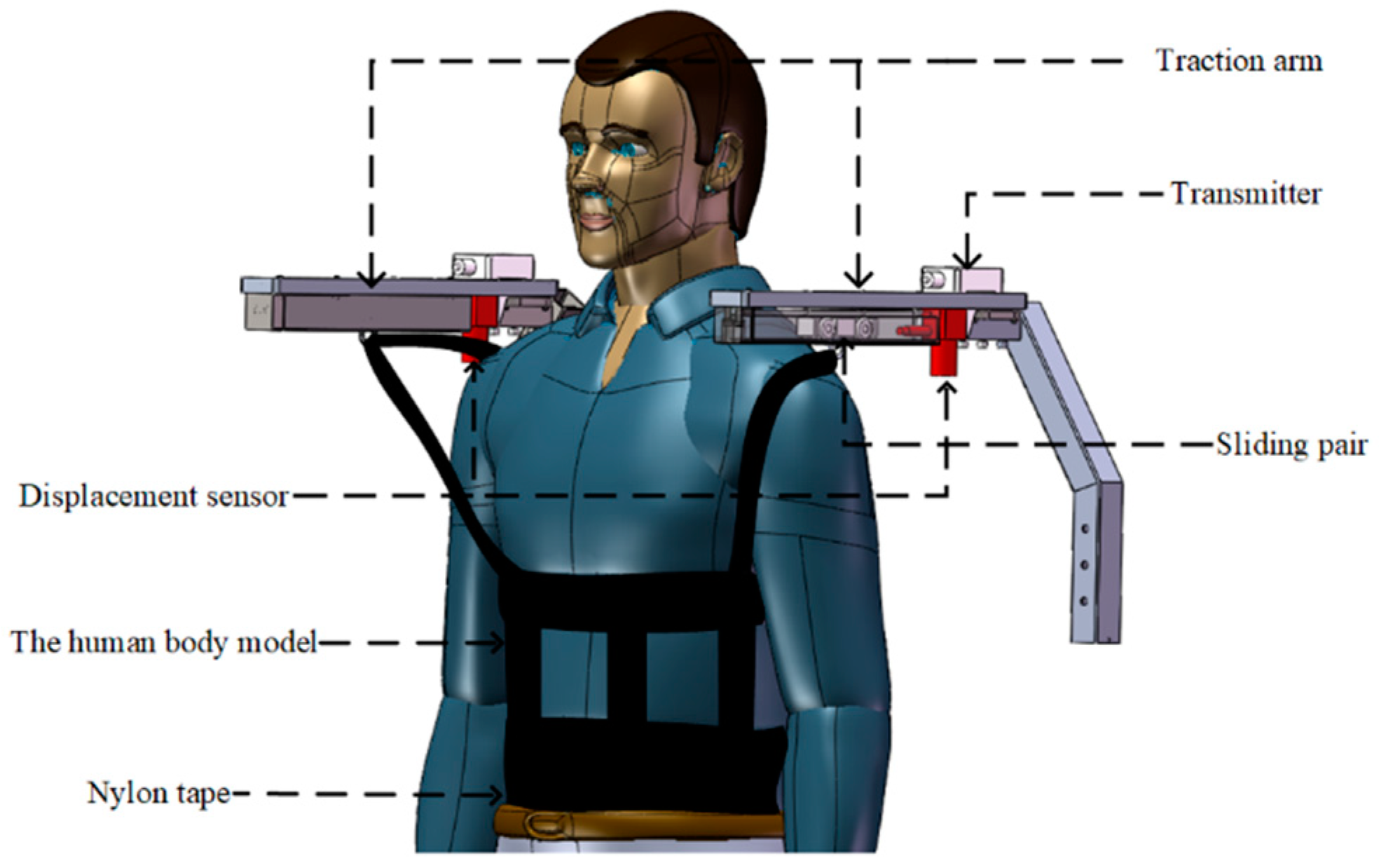
The lower limbs of stroke patients cannot provide sufficient strength support for the body, and the upper limbs also have dysfunction, and the affected side of the body is in an uncontrolled state, and cannot provide effective assistance for the patient’s recovery. During the rehabilitation, the patient’s healthy upper limb often grips objects to maintain body balance. Although the robot BWS system helps the patient achieve physical balance, the patient still obtains a sense of psychological security by gripping the object, and cannot independently complete the human-machine collaborative rehabilitation. Doctors or family members are required to operate the robot to help patients achieve the goal of lower limb rehabilitation training. A human-computer interaction system was developed for this problem. The system recognizes the patient’s movement state through the displacement sensor, and feeds the data back to the robot control system to achieve the goal of the robot actively following the patient’s movement. The human-machine interaction system of the robot is shown in Figure 3. The displacement sensor is installed at the end of the linear track. The track has a built-in wheel-type moving slider. The effective stroke of the wheel-type moving slider in the linear track is 125 mm. The moving slider is connected to one side of the patient’s body by a nylon strap. The patient pulls the slider to move forward or backward during walking. The displacement sensors on both sides sense the movement of the slider and control the robot to move forward. If the patient wants to turn, the sliding block in the track moves forward on one side and backward on the other side. The robot recognizes the patient’s movement state based on this and then performs corresponding movement to achieve the goal of human-computer interaction control.
2.2. Telerehabilitation Interactive System
2.2.1. Framework of Telerehabilitation Robot Interaction System
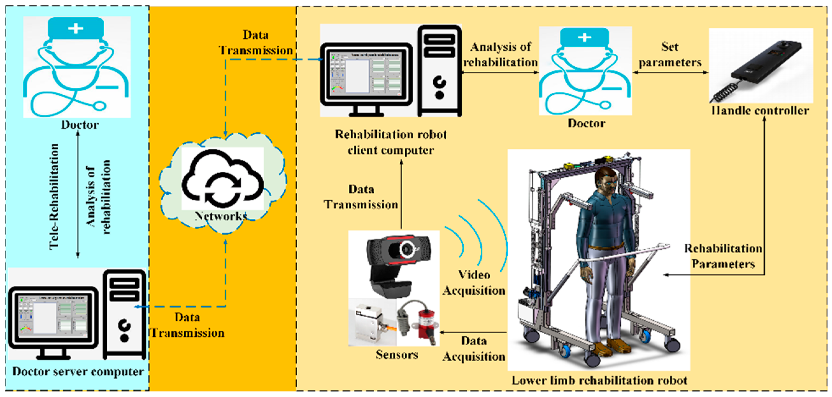
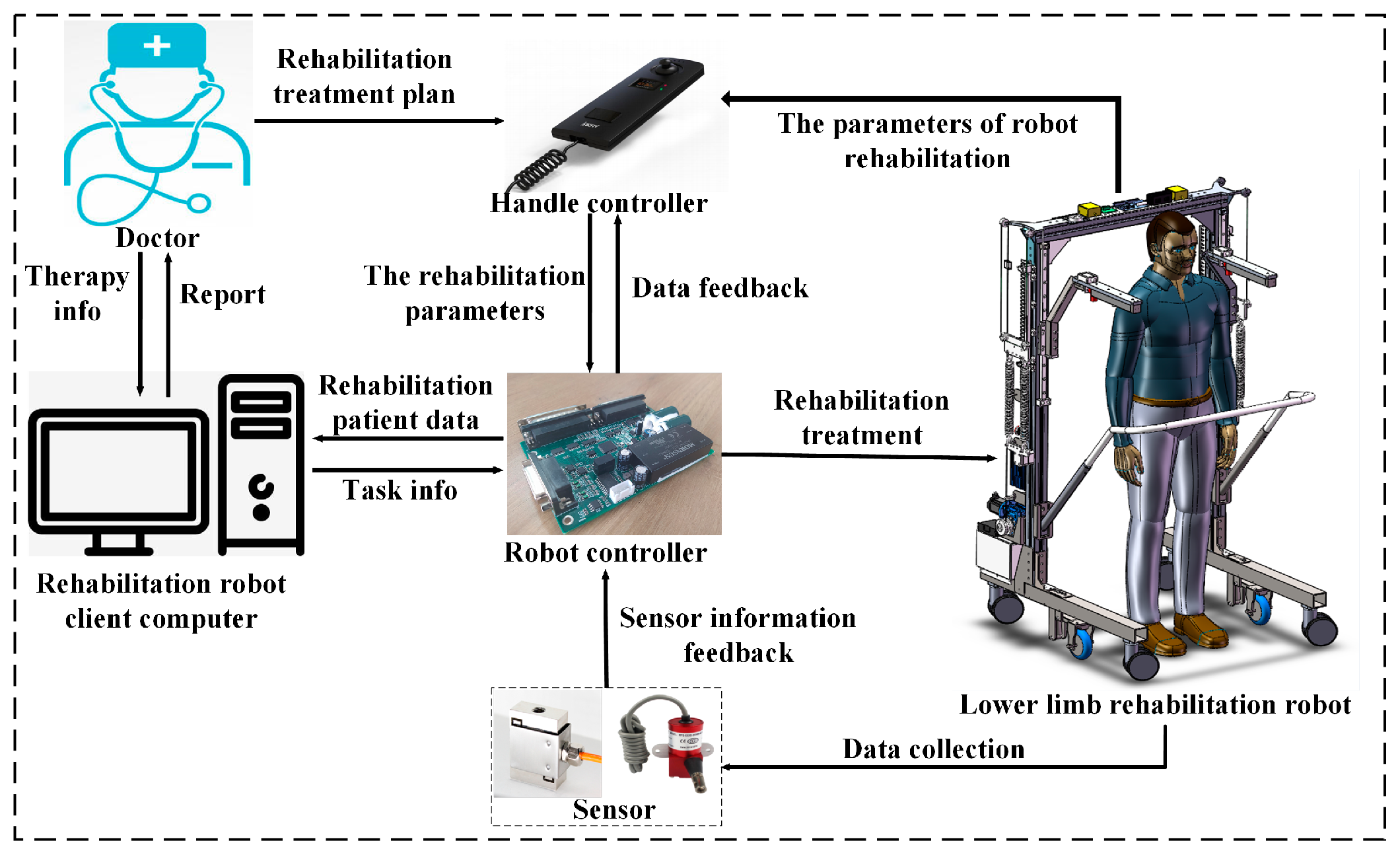
Rehabilitation robots need to be used by professionally trained doctors. If every patient relies on the doctor’s operation and supervision, it will greatly increase the doctor’s workload. In this paper, we design a web-based robot remote rehabilitation interactive control system. Using this system, the doctors can take care of multiple rehabilitation robots on the server-side and distribute the rehabilitation training tasks to different patients. Patients or their family members can click to confirm the rehabilitation training tasks on the rehabilitation robot side to complete the training settings. These significantly reduce the doctor’s workloads. The content of the rehabilitation training task includes the number of rehabilitation robots, patient information, training range, training speed, and training time. Doctors can then simplify the operation of the rehabilitation robot by remotely setting the rehabilitation training parameters. Through the analysis of the functions and requirements of the lower extremity rehabilitation robot system, we then adopt a network-based client/server (C/S) architecture to form a remote control system. Figure 4 describes the framework of the lower extremity rehabilitation robot remote interaction system. The telerehabilitation interactive control system consists of four components: a doctor server computer, a rehabilitation robot client computer, a lower limb rehabilitation robot, and a computer network.
The server-side computer of the doctor is convenient for the doctor to guide the patient’s rehabilitation training and manage the patient’s rehabilitation log. It can distribute rehabilitation training tasks to rehabilitation robots. The doctor’s server computer also displays the patient’s rehabilitation data in real-time and helps the doctor to understand the patient’s rehabilitation training status. The rehabilitation robot is controlled by the client computer at the rehabilitation site. It mainly completes the motion control of the rehabilitation robot and accepts the server-side rehabilitation training tasks, realizes the analysis of the rehabilitation task commands, and sets various parameters of the rehabilitation robot. The network acts as a bridge to transmit the information between the server and the rehabilitation robot client. The rehabilitation robot saves training data in the client’s local database. Doctors and patients’ family members can also access the local database through the network to view the training data of the patients.
2.2.2. Hardware of Robot Control System
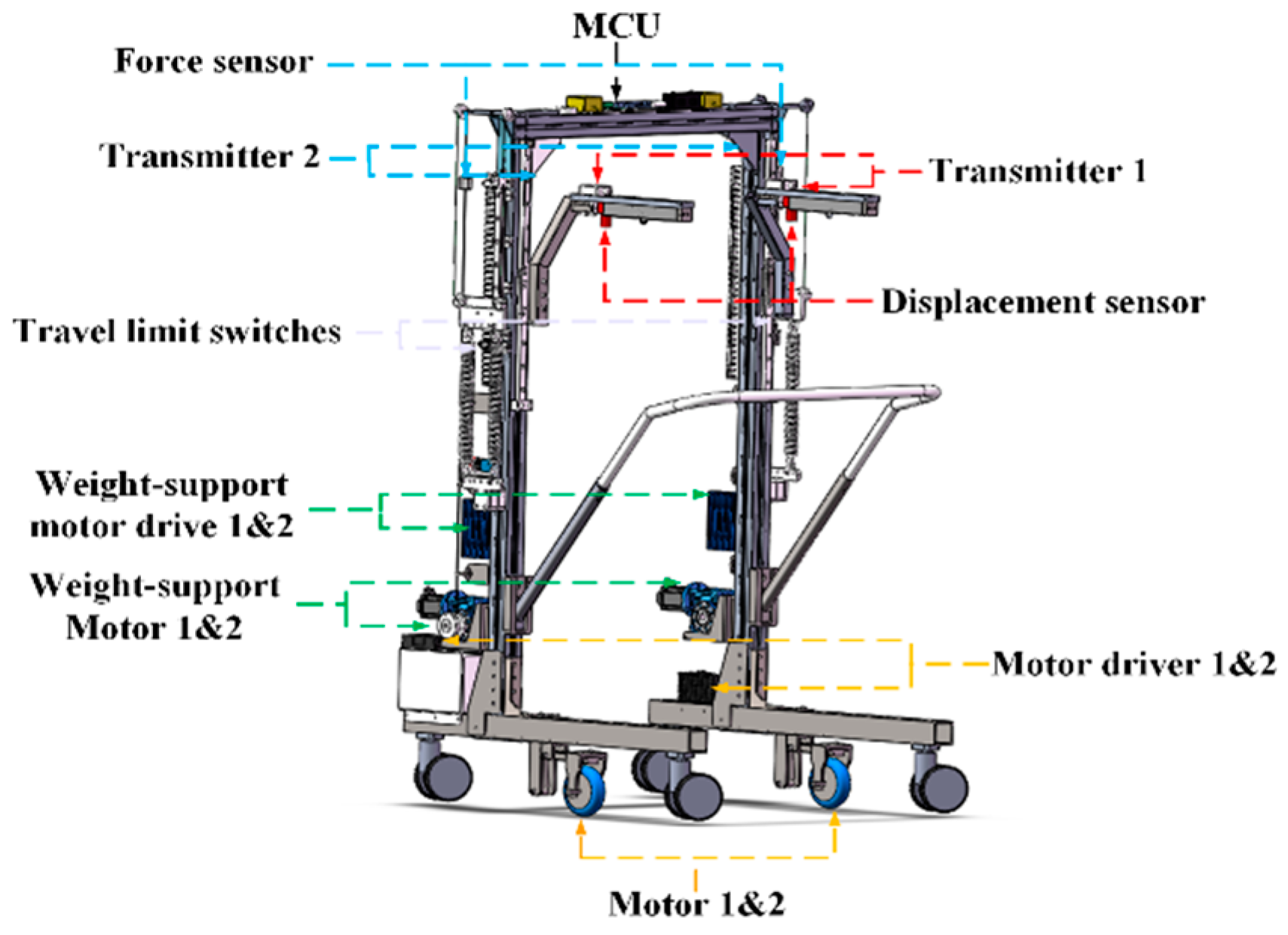
The main control module of the rehabilitation robot is located in the top box of the structure. The control module is composed of a core control board, a power acquisition unit, a sensor transmitter unit, and a power distribution unit. Other components are a power switch, an emergency stop button, two limit switches, a 24 V lithium battery, two hub motor drivers, and two BWS motor drivers. The control system of the rehabilitation robot is shown in Figure 5. The system is divided into four sub-modules: force and position information sampling module, body panel human-computer interaction input module, data output module, and a communication module with the rehabilitation robot client. Doctors can formulate the rehabilitation programs based on the clinical conditions of the patients’ lower limbs and set the rehabilitation parameters of the robot through the operating handle of the robot. The rehabilitation parameters include the BWS value, rehabilitation training time, robot movement speed, etc. Using the operating handle reduces the difficulty of robot operation and simplifies the operation of the rehabilitation robot. The specific value of BWS is fed back by the force sensor on the digital display of the operating handle. The doctor can recognize the change in the BWS value in real-time and make appropriate adjustments according to the patient’s lower limb strength. During the patient’s exercise rehabilitation process, the robot’s force and displacement sensors also collect the patient’s lower limb strength change data and body motion state data. The data is transmitted to the control core for processing and displayed on the host computer system interface. Doctors can then analyze the patient’s rehabilitation data through the host computer system. Based on this data, the doctor can evaluate the patient’s rehabilitation effect and formulate a new round of rehabilitation plans for the patient.
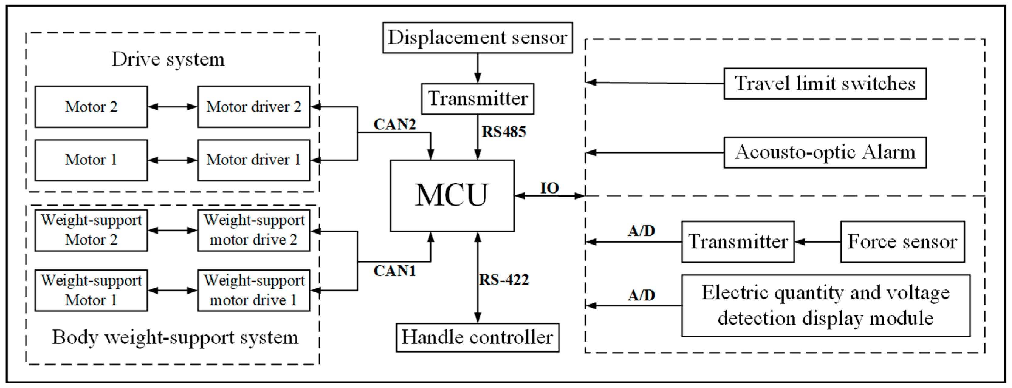
The robot control system is composed of three sub-systems: a BWS system, a sensor information feedback system, and a human-machine interaction drive system. The rehabilitation robot control system uses an MCU with Cortex-M7 as the core, with the main frequency of 400 MHz. The hardware framework of the robot system is shown in Figure 6. In the BWS system, the operating handle uses RS-422 to establish two-way data communication with the MCU of the robot control core. The operating handle can be further used to set the BWS value. In the sensing information feedback system, the real-time value of the force sensor in the BWS system is sent to the MCU for processing through the A/D module and displayed on the operating handle screen through serial communication. The doctor is aware of the specific values of the current adjustment parameters and can make appropriate fine adjustments to the parameters according to the patient’s comfort requirements. The control core MCU also receives instructions from the operating handle and transmits the corresponding commands to the BWS system drivers 1 and 2 through the CAN1 bus. The two motors support the patient’s weight and adjust the patient’s body balance according to instructions. The patient training data collected by the force sensor needs to be sent to the MCU through the A/D module. If the force feedback data is close to the set value and fluctuates in a small range around the set value, it indicates that the patient’s lower limb strength is recovering well. If the force feedback data is far from the set value and is in a large fluctuation range, then it indicates that the patient’s lower limb strength is insufficient and still depends on the BWS system to maintain the balance of the body. In the human-machine interactive system, the robot’s motion modes are divided into manual mode and automatic mode. In the manual mode, the robot’s motion is controlled by the upper lever of the handle by the doctor, and the hub motor drivers 1 and 2 receive control commands through the CAN2 bus. After the patient’s body balance and lower limb strength are restored, the robot can be then switched to the automatic mode to assist the patient in sports rehabilitation. In the automatic mode, the robot detects changes in the patient’s motion posture through the displacement sensors of the sensing information feedback system. The patient motion information is also sent to the main controller MCU via the transmitter module via RS-485. The main controller sends motion instructions to the hub motor drivers 1 and 2 through the CAN2 bus and controls the robot to follow the patient in the appropriate motion posture. The patient realizes the autonomous control of the robot, achieving the effect of coordinated movement and active movement with the robot. The power display of the robot is isolated from 24 V by a linear optocoupler, and the output signal is 0–5 V. The conversion is also completed by the chip’s own A/D. The remaining functions such as limit switches and sound and light alarms, realize various information feedback of the robot through the I/O interface and MCU. The hardware and sensing system of the rehabilitation robots are illustrated in Figure 7.
2.2.3. Design of Robot Remote System
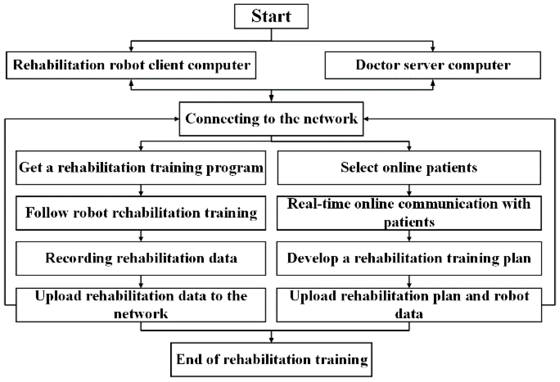
By turning on the robot’s remote system and getting it connected to the Internet, the doctor server computer can communicate with the rehabilitation robot computer, watch the data changes of the equipment in real-time, and read the rehabilitation data in the local database. Doctors can evaluate the patient’s condition and formulate a rehabilitation plan based on the patient’s rehabilitation records in the database. This enables the doctor to make appropriate modifications to the patient’s rehabilitation training plan. The doctor also adjusts the training parameters of the rehabilitation robot through the server computer and formulates a new rehabilitation training program. The rehabilitation robot performs a new stage of rehabilitation auxiliary treatment for patients based on the new rehabilitation training program. The rehabilitation data is then shared between the client-side of the rehabilitation robot and the doctor’s server-side computer. Such information includes the patient’s personal information and the robot’s auxiliary rehabilitation parameters. The remote system operating process is shown in Figure 8.
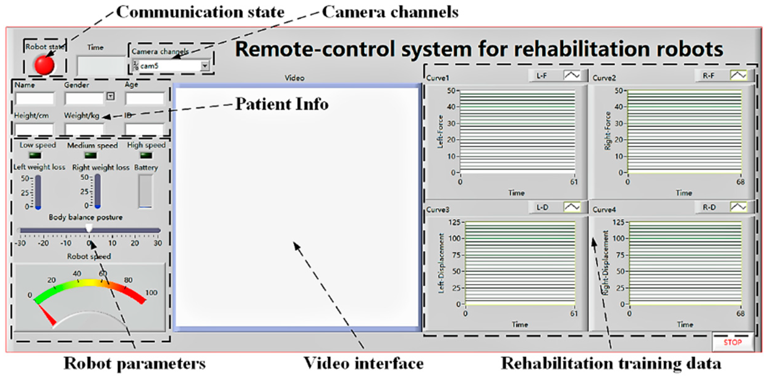
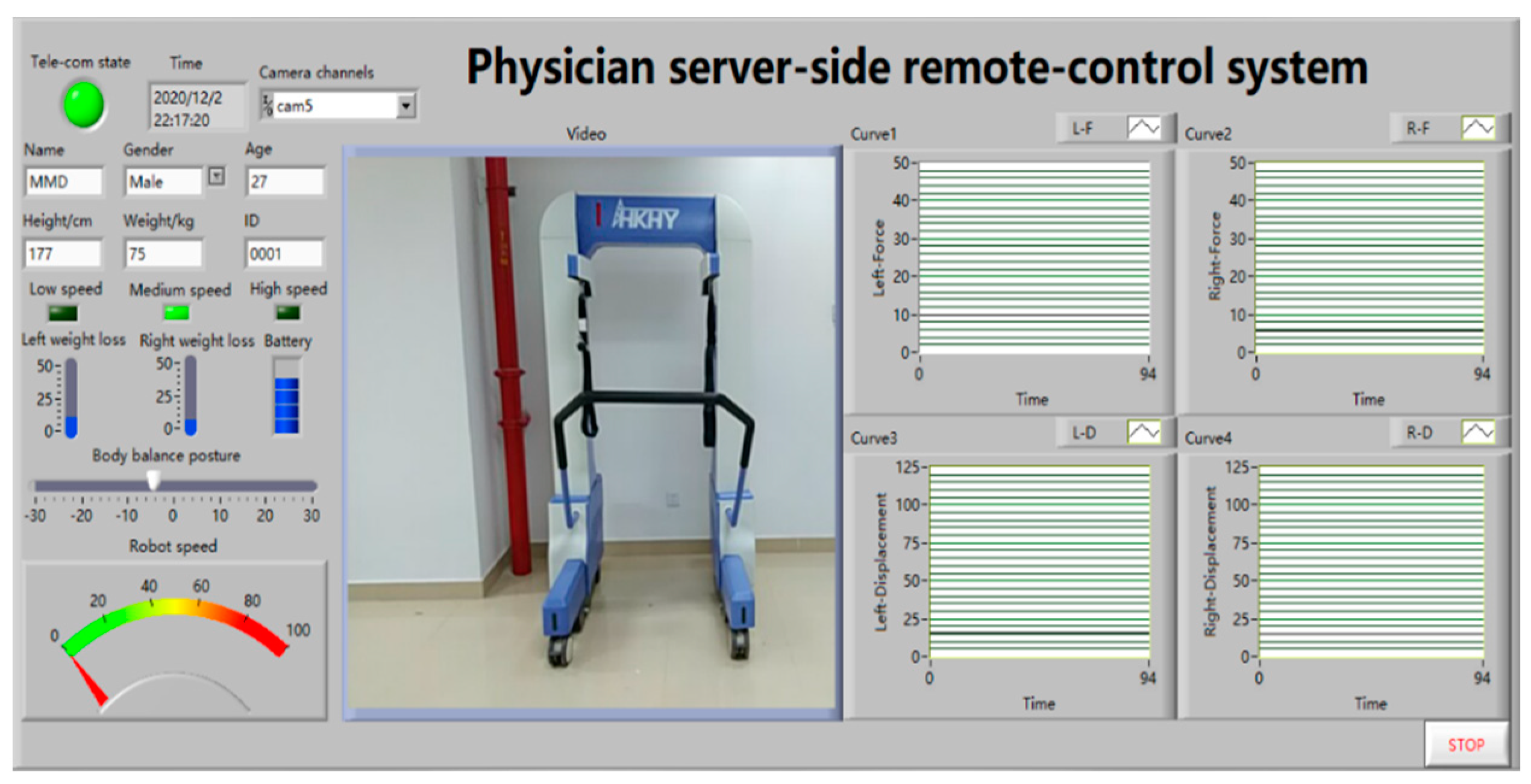
The interactive interface of the rehabilitation robot is designed by LABVIEW software. (LABVIEW was developed by National Instruments Corporation, headquartered in Austin, TX, USA). The development interface consists of a front panel and a rear panel. The front panel includes a digital control, and a digital display. The interface information includes the robot’s operating status and various rehabilitation parameters, the patient’s personal information, remote real-time video images, and the movement data change curve during the patient’s rehabilitation. The back panel is a graphical representation of the control commands that implement the program structure and define the control logic. The feedback data from the robot sensors is filtered and noise-reduced in the control core MCU. This data is then converted to digital signals for direct display on the front panel of the interactive interface. The communication module allows the client computer system of the rehabilitation robot to establish data transfer with the rehabilitation robot and realizes wireless data transmission through the WIFI module of the MCU. We further note that medical data requires a high level of data integrity and security. Audio and video data are used as auxiliary monitoring data, which has high requirements for the smoothness of the call. The remote system uses the TCP protocol to access the control system software as the. The rehabilitation robot also uses socket technology to realize the remote transmission of patient training data. The remote system uses an IP camera to transfer the patient training images from the rehabilitation robot to the doctor server. Doctors can remotely observe the rehabilitation process of patients at the rehabilitation training site. The IP camera is a camera that combines a traditional camera and network technology. It transmits the video to the doctor’s server computer through the Internet. The doctor supervises the on-site rehabilitation training through the computer control system software. The interface of the rehabilitation robot remote control system is illustrated in Figure 9.
After the control system function panel is built, it is necessary to compile the acquisition program for the displacement and tension sensors. The tension sensor collects the tension signal generated by the patient to ensure the accuracy of the force control. The displacement sensor also collects the patient’s movement posture signal to ensure the robot responds to the movement. The displacement sensor then converts the linear mechanical displacement into an electrical signal to realize counting. Note that there is a corresponding proportional relationship between the two. The displacement sensor adopts a digital output mode and has two signal acquisition channels A and B. The data of the two channels are then processed to obtain the changing track of the displacement. The displacement sensor is fixed at the upper end of the traction arm and connected with the linear guide slider through a wire rope. With the movement of the slider, the wire rope is then driven to realize the displacement change, thereby realizing the collection of the position tracking. The back panel of displacement and tension sensor counting is shown in Figure 10.
3. Results
3.1. Experimental Research of Rehabilitation Robot Control
3.1.1. Experiments of Robot Telecommunication
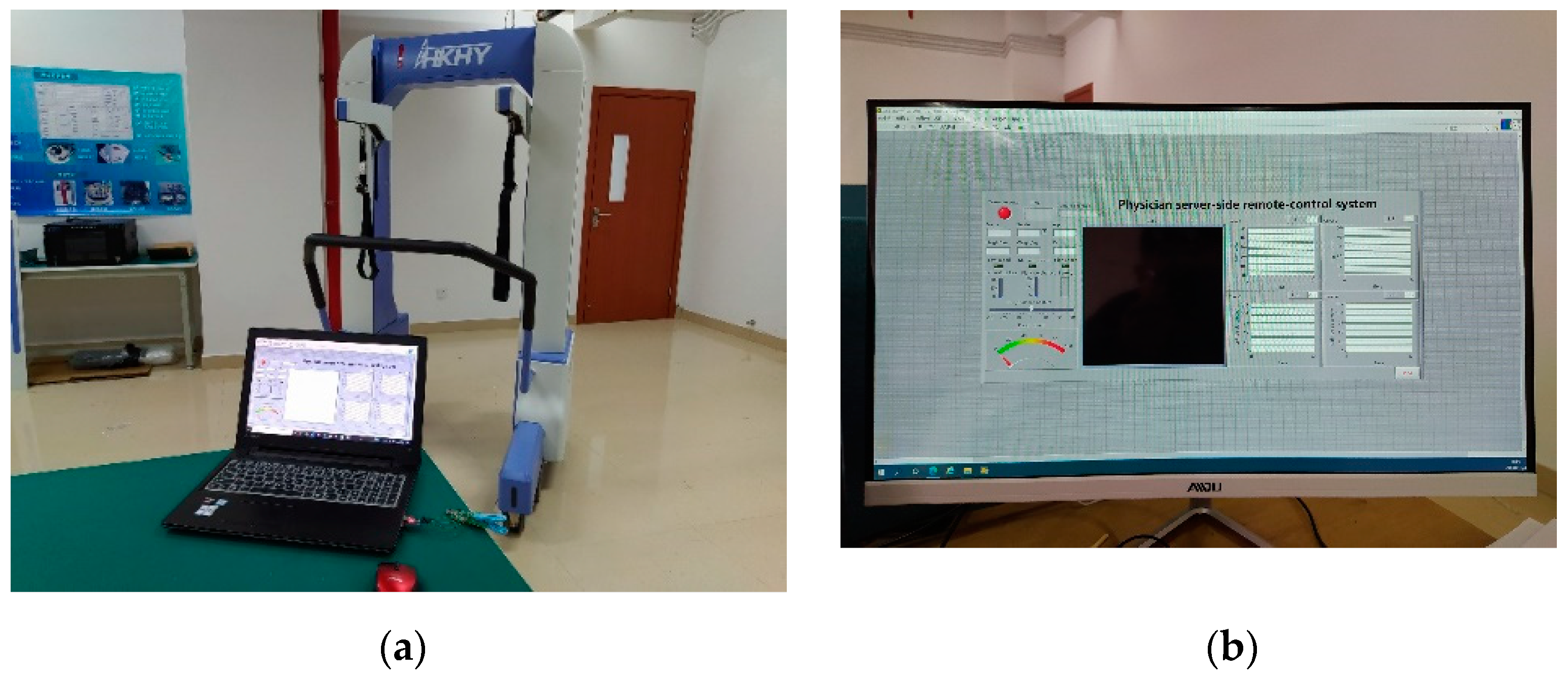
The rehabilitation robot control system is a multi-variable and multi-level system. The rehabilitation robot body and remote control systems require high performance to ensure the accuracy of control. To verify whether the rehabilitation robot remote control system meets the design requirements, we test the control system hardware and software. The remote communication experiment verifies the accuracy of data communication in the remote system and further confirms the stability of the system during the communication process. The test items include the robot state logic test, robot rehabilitation parameter setting test, patient and robot information management test. A test platform for the rehabilitation robot body system and remote control system was built. The rehabilitation robot test platform is composed of the rehabilitation robot body and a computer. The remote doctor’s terminal operating platform is a computer connected to the Internet. The experimental platform for the rehabilitation robot end system and the doctor end remote system control platform are presented in Figure 11a,b.
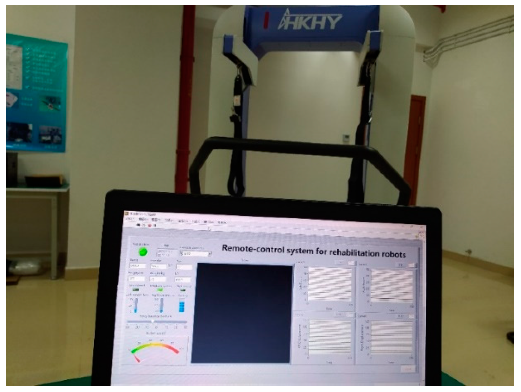
We turned on the control system software of the rehabilitation robot and the electrical system of the robot body. The robot then established a data communication link between the computer of the rehabilitation robot and the robot body system. The successful interface of the client computer of the rehabilitation robot is shown in Figure 12. The green indicator of the robot status in the control system software interface indicates the client is successfully connected to the robot body, and the rehabilitation robot has completed the initialization of various rehabilitation parameters. We then adjusted the state logic of the rehabilitation robot through the control system software or the robot operating handle. The state of the robot is indicated by the indicator light on the software interface. During the experiment, the speed mode and BWS value of the robot were adjusted by the handle. The status of the robot speed mode indicator on the software interface and the force value were changed accordingly, which verified the robot’s state logic reached the predetermined requirements. The robot state logic test is shown in Figure 13a,b.
The doctor server computer and the rehabilitation robot client computer are connected through the Internet. The successful remote connection interface of the doctor server computer is shown in Figure 14. If the robot status indicator in the software system interface is green, then the doctor’s and the rehabilitation robot’s client computer successfully establish data communication links. The computer communication experiment between the rehabilitation robot client and the doctor verifies that the system realizes remote data transmission and feedback.
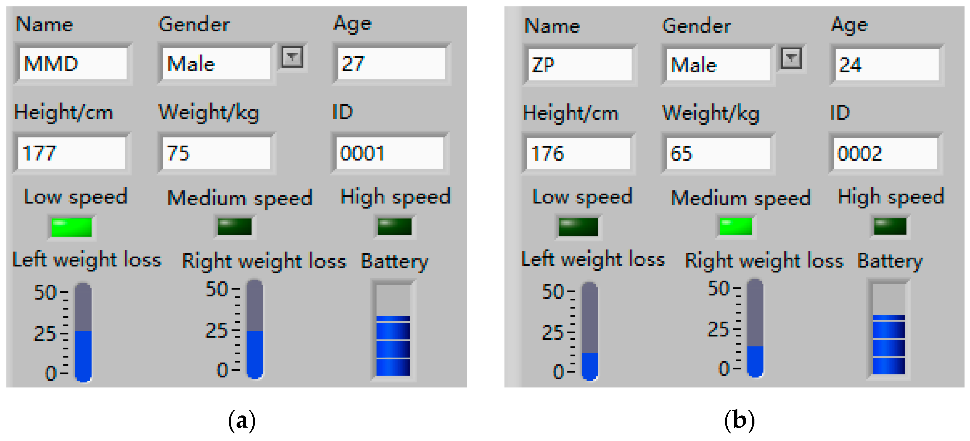
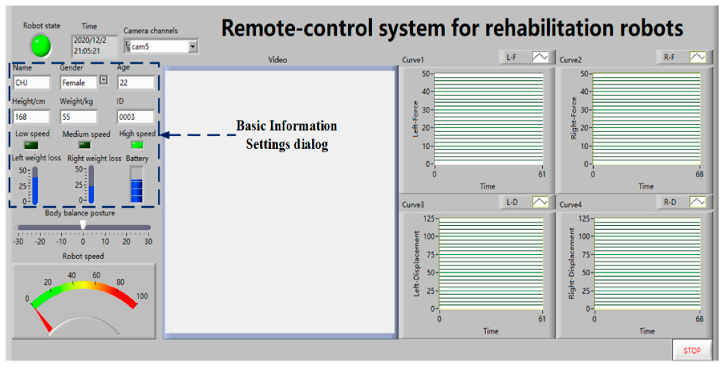
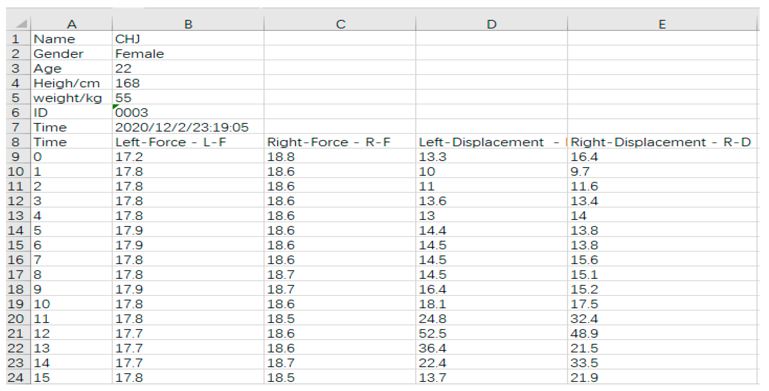
The doctor enters the patient’s basic information and robot operating parameters through the rehabilitation robot computer. The basic information setting dialog box is shown in Figure 15. The remote doctor’s computer receives various rehabilitation data of the patient through the patient’s ID number. The doctor adjusts the operating parameters of the rehabilitation robot according to the patient’s current state and transmits them to the rehabilitation robot client through the network. The robot client receives the latest operating parameters and revises the patient’s rehabilitation training. Rehabilitation data, such as patient information and operating parameters of the rehabilitation robot, are also stored in the background database. Rehabilitation data can be also exported in the form of files to facilitate subsequent diagnosis and analysis by rehabilitation doctors. The export file of the patient rehabilitation data is shown in Figure 16.
3.1.2. Experiment of Rehabilitation Training Data Acquisition
In telerehabilitation, video communication is an important tool for effective communication between the doctors and the patients. The system uses a USB camera to collect video data. Before video acquisition, the channel number of the camera needs to be set. The video communication window is shown in Figure 17.
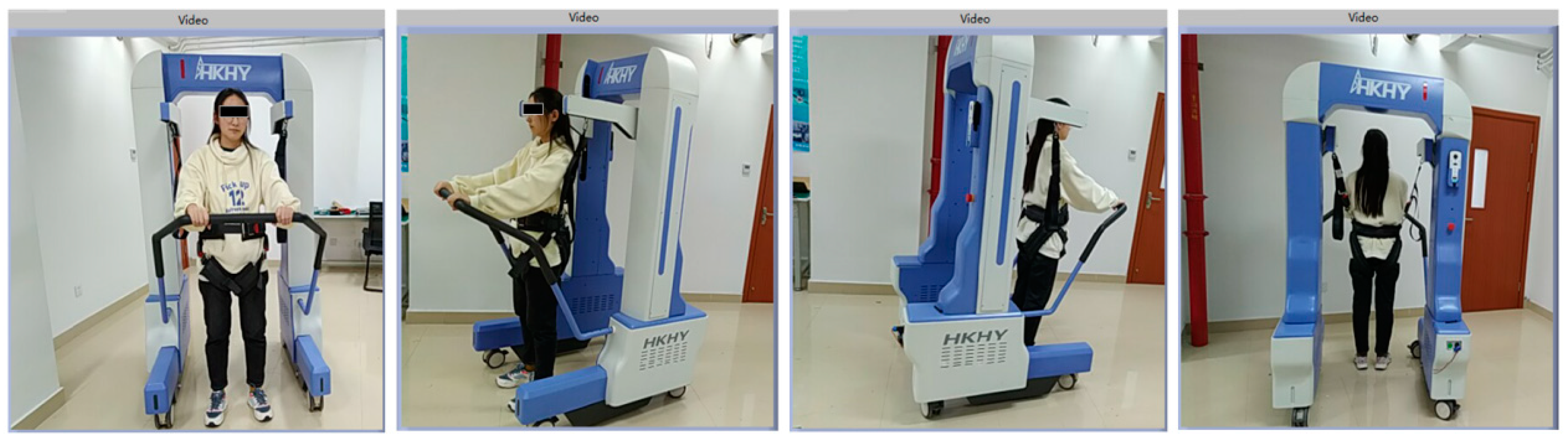
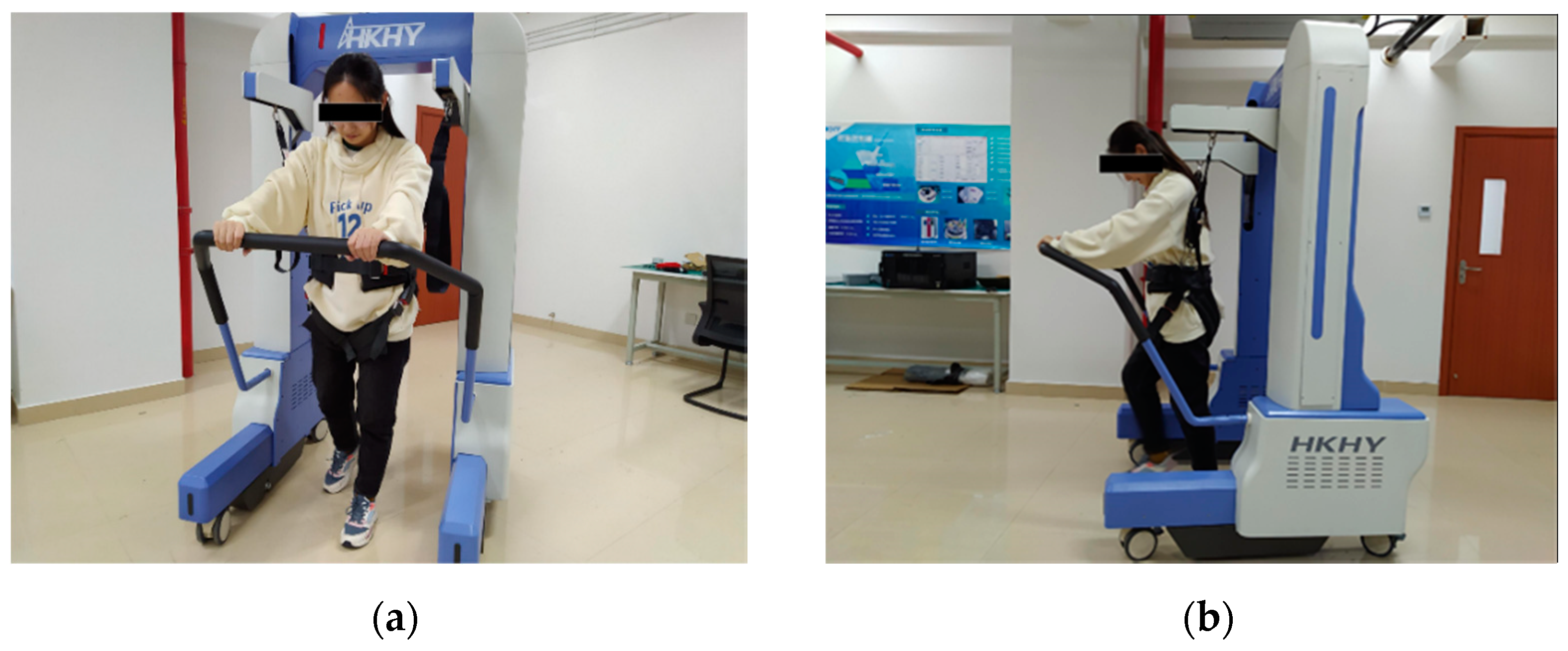
In the exercise data acquisition experiment of the rehabilitation robot, a volunteer with a height of 168 cm and a weight of 55 kg was selected to participate. During the experiment, the volunteer wore weight-support clothing. The weight support values on the left and right sides of the volunteer’s body were set to 17–18 kg and 18–19 kg, respectively. This was to ensure that the volunteer’s body is in an approximately balanced state. The robot motion speed mode was set to low-speed mode, and the control mode was set to free motion mode. There is no need to manually control the motion of the robot, and the system collects the change curve of the volunteer’s BWS value and the posture change curve during the rehabilitation training. The experiment mainly tested four types of rehabilitation in rehabilitation training, including walking in a straight line, turning left on the spot, turning right on the spot, and standing in the original squat. The robot recognizes the changes in the patient’s body posture and BWS value in the free motion mode according to the sensor data. The experimental site is shown in Figure 18a,b.
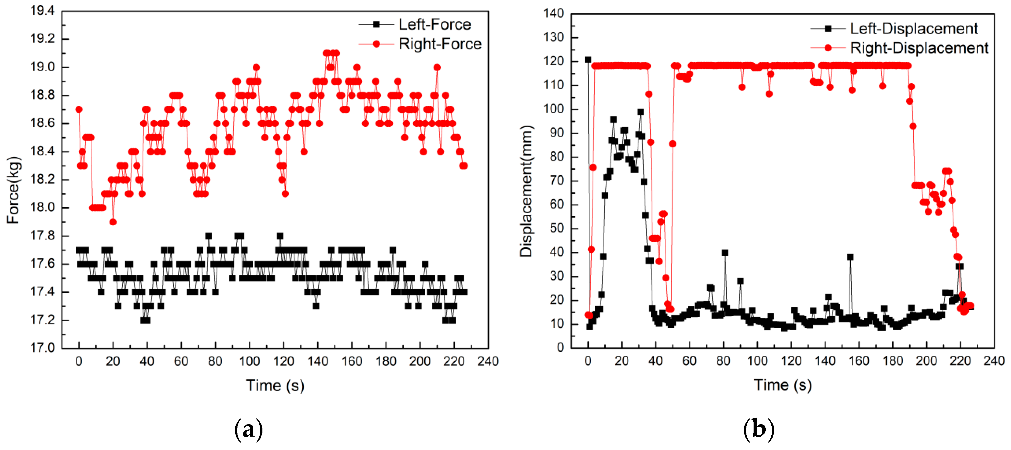
Straight-line walking training with the help of rehabilitation robots is the main form of rehabilitation for the patients. In the control system, if the displacement difference between the left and right sides is greater than 20 mm, then the robot adopts a steering motion. If it is less than 20 mm, then the robot performs a linear motion. The straight-line walking experiment is conducted assuming that the initial weight support is unchanged. The collected data is shown in Figure 19a,b. From Figure 19a, it can be seen that the weight support values on the left and right sides of the body fluctuate within the set interval during straight walking, and there is no large abrupt change in the value. It can be also seen from Figure 19b that in the straight walking, the changing trend of the displacement data curve on the left and right sides are synchronized and consistent. The two sliders are also displaced to the top of the track in 75–85 s, but the displacement variation data is mostly in the range of 10–70 mm. Furthermore, the difference between the left and right displacement data is kept within a small range. The robot can accurately recognize the movement posture of the human body and realize the straight-line following movement.
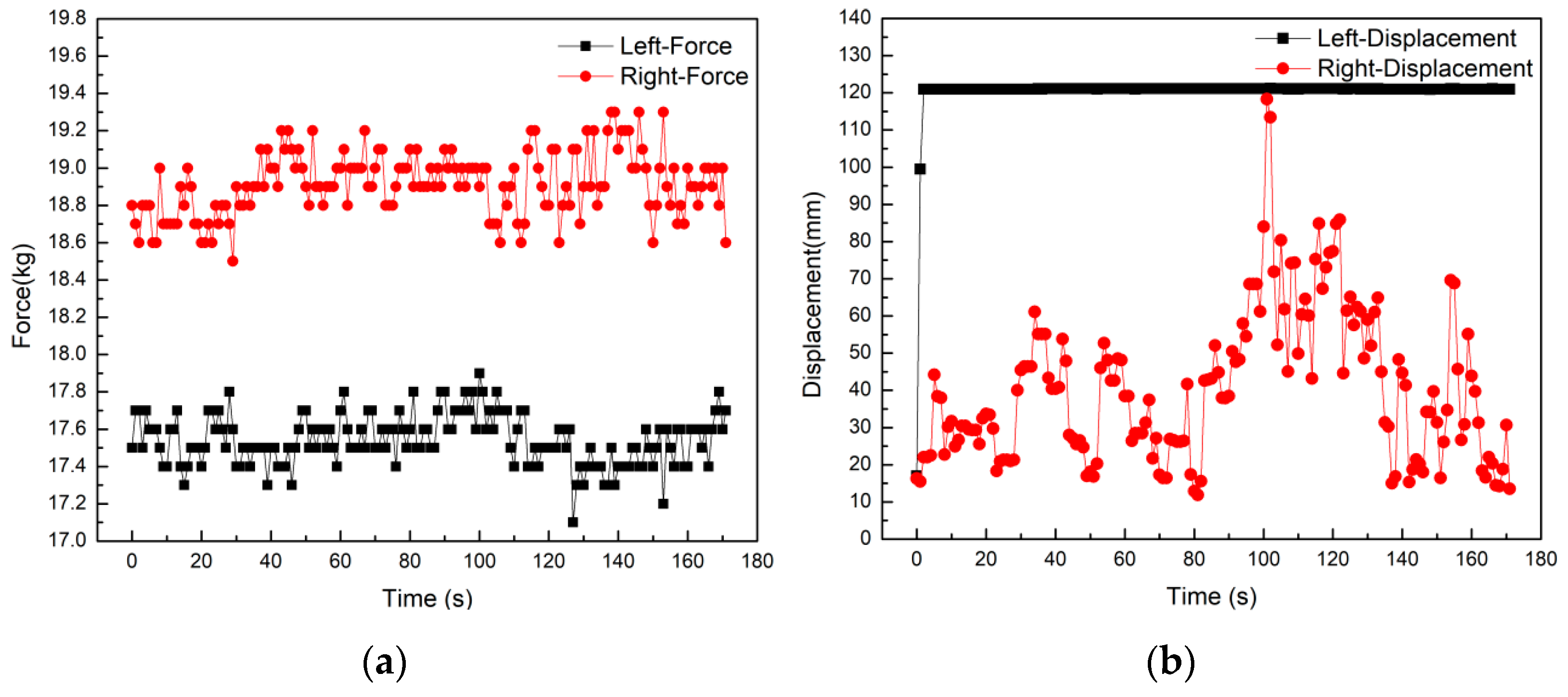
In situ steering is a function that is often used by the patients during the rehabilitation process. Under the condition that the initial BWS value is constant, three sets of repeated experiments were carried out for the left and right in situ steering in the experiment. The data curves are shown in Figure 20a,b and Figure 21a,b. The body posture corresponding to the left turning is the left shoulder backward and the right shoulder forward. The displacement data curve in Figure 20b shows that most of the time during the whole steering process the value of the right displacement curve is at the maximum value. The value of the displacement curve on the right is stable within the fluctuation range of 10–20 mm. In the volunteer experiment, there was a short-term turning and discontinuity problem, and the robot produced a turning stop and direction swing. Correspondingly, there was a large increase in the left displacement curve within 10~50 s, and then it returned to the fluctuation range. The displacement curve on the right has a significant decrease, and then it returns to the maximum range. The body posture corresponding to the right turning is the right shoulder back and the left shoulder forward. It can be further seen from the displacement data curve in Figure 21b that the value of the left displacement curve is always at the maximum state during the whole turning process. The value of the displacement curve on the right fluctuates in a larger range within the interval of 15–70 mm. During the experiment, when turning, the volunteers moved slowly and discontinuously. Every time the body turned one angle, they made a very short pause, and the right slider would slide to the initial position. Therefore, the displacement curve on the right fluctuates in a larger interval. This confirms that the human-computer interaction system can correctly recognize the movement posture information of the human body and feed it back to the system interface through the data curve.
In this experiment, the BWS value is constant, and the BWS values on the left and right sides are in the range of 17–18 kg and 18–19 kg, respectively. It can be seen from Figure 20a that the average value of the left side BWS when turning left is about 17.53 kg. The average BWS value on the right is about 18.58 kg. It can be also seen from Figure 21a that the average value of the right side BWS while turning right is about 18.91 kg. The average BWS value on the left is about 17.44 kg. For the BWS value of the same side of the body when turning left and right. Therefore, it can be seen that the BWS value of the turning side of the body is increased. Although the amount of change is small, the human body posture information can be recognized by the change of the force value.
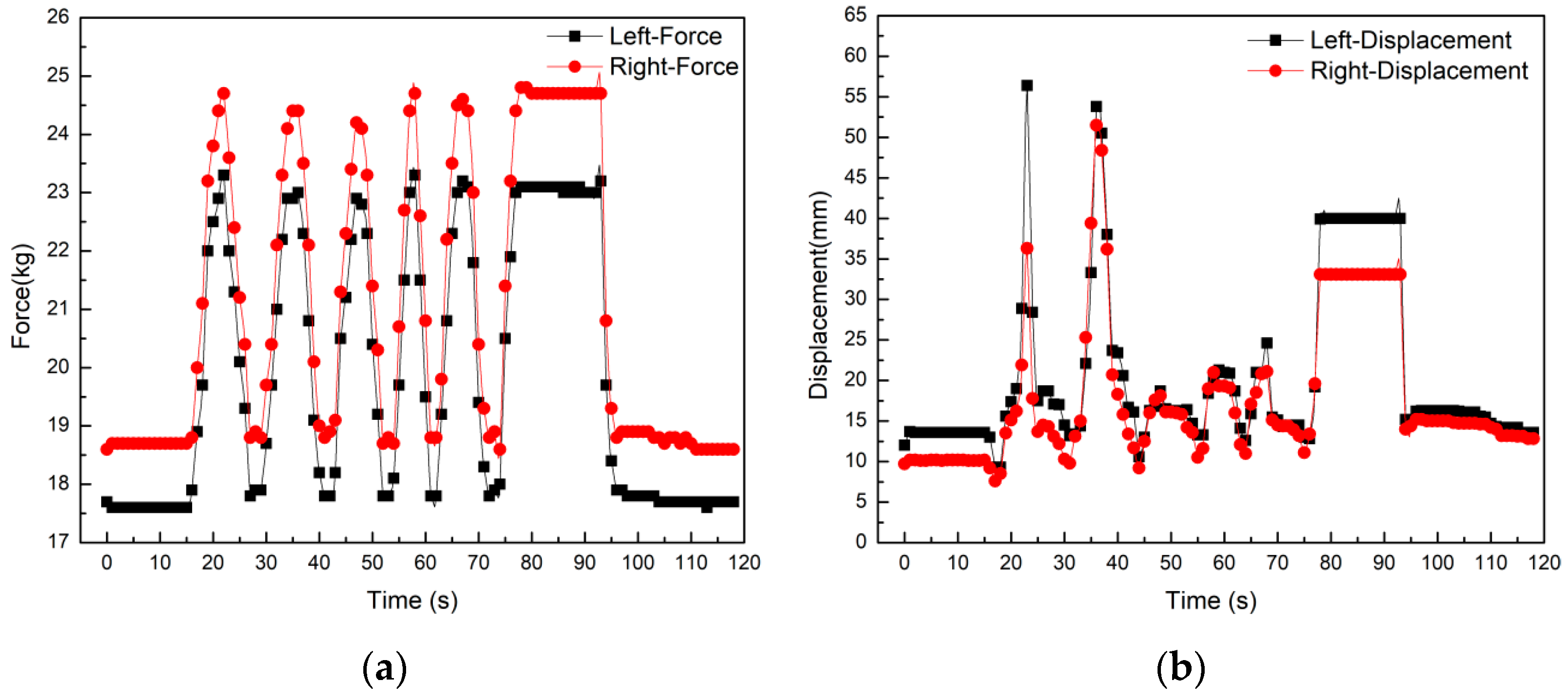
The original squat and stand-up action are a relatively regular posture. Under the condition of keeping the initial BWS value unchanged, the force value is gradually increased during the squatting process, whereas it is gradually decreased during the rising process. In the experiment, 5 sets of original squatting and standing movements were repeated, and the data curve is shown in Figure 22a,b. It is seen in Figure 22a that the tension data curve is changing in a relatively large interval. The left side tension value varies from 17.5 kg to 23.5 kg, and the right side tension value varies from 18.5 kg to 24.5 kg. The curve trend has the characteristics of synchronous consistency and periodic fluctuations. The volunteers maintained a squatting posture for some time during the experiment. In the 75~95 s time interval, the tension curve also shows a horizontal state accordingly. It is proved that the value of the sensor’s tensile force is in a constant state. It can be seen from Figure 22b that the fluctuation range of the displacement curve of the volunteers squatting and standing on the spot is relatively small. The entire fluctuation range is about 10–20 mm, and there are occasionally sudden changes in displacement. The data in this experiment provides a reference for the follow-up control. By setting the trigger threshold in the autonomous control motion mode of the robot, misleading the robot by the patient is prevented. This increases the safety of the system and prevents accidents due to the misoperation of the patients’ posture.
4. Conclusions
To address the needs of the stroke patients, in this paper, a robot that enables telerehabilitation was developed. We first introduce the electromechanical structure design and working principles of the rehabilitation robot. The development process of the robot control system and the remote rehabilitation system are then discussed. Through extensive experiments, we then show that the electromechanical structure design of the rehabilitation robot can meet the rehabilitation training needs of stroke patients. The proposed robot helps the patient to keep body balance while reducing the burden of walking on the patient’s lower limbs. The human-computer interaction system of the lower limb rehabilitation robot also shows high performance and can accurately recognize the motion postures. Through the human-computer interaction system, the goal of the robot to actively follow the patient’s movement is also realized, and the patient’s initiative in the rehabilitation process is improved. This paper builds a telerehabilitation interactive control system based on the network-based C/S architecture. After completing the software and hardware design of the rehabilitation robot control system, experiments are carried out on the robot control system. The rehabilitation robot system achieves the objectives of operational parameter transmission, patient motion data acquisition, and video communication between doctor and patient. The remote control system further achieves the objectives of robot status monitoring, patient information management, and patient-specific rehabilitation guidance. It is also shown that the remote control system of the rehabilitation robot meets the expected design requirements. The data collected during the rehabilitation process enables doctors to carry out in-depth research on patients’ rehabilitation treatment and is used to improve rehabilitation effects and efficiency. The remote rehabilitation system provides patients with more humane services, and provide long-term health guidance and support for disabled patients in remote areas. The designed system significantly reduces the patient’s family burden and social medical costs.
Author Contributions
Data curation, M.M.; Formal analysis, M.M.; Funding acquisition, X.G.; Project administration, X.G.; Resources, W.Z.; Writing-original draft, M.M.; Writing-review & editing, M.M. and X.G. All authors have read and agreed to the published version of the manuscript.
Funding
This work is supported by the National Key R and D Program of China (grant no. 2020YFC2008503).
Institutional Review Board Statement
Not applicable.
Informed Consent Statement
Informed consent was obtained from all subjects involved in the study.
Data Availability Statement
Data sharing not applicable.
Acknowledgments
The authors are grateful to Peng Zhao and Hongjuan Che their valuable help in collecting data.
Conflicts of Interest
The authors declare no conflict of interest.
References
- Calvaresi, D.; Marinoni, M.; Dragoni, A.F.; Hilfiker, R.; Schumacher, M. Real-time multi-agent systems for telerehabilitation scenarios. Artif. Intell. Med. 2019, 96, 217–231. [Google Scholar] [CrossRef] [PubMed]
- Galea, M.D. Telemedicine in rehabilitation. Phys. Med. Rehabil. Clin. 2019, 30, 473–483. [Google Scholar] [CrossRef] [PubMed]
- Volterrani, M.; Sposato, B. Remote monitoring and telemedicine. Eur. Heart J. Suppl. 2019, 21, M54–M56. [Google Scholar] [CrossRef] [PubMed] [Green Version]
- Sarfo, F.S.; Ulasavets, U.; Opare-Sem, O.K.; Ovbiagele, B. Tele-rehabilitation after stroke: An updated systematic review of the literature. J. Stroke Cerebrovasc. Dis. 2018, 27, 2306–2318. [Google Scholar] [CrossRef] [PubMed]
- Tyagi, S.; Lim, D.S.; Ho, W.H.; Koh, Y.Q.; Cai, V.; Koh, G.C.; Legido-Quigley, H. Acceptance of tele-rehabilitation by stroke patients: Perceived barriers and facilitators. Arch. Phys. Med. Rehabil. 2018, 99, 2472–2477.e2. [Google Scholar] [CrossRef]
- Molinaro, A.; Micheletti, S.; Pagani, F.; Garofalo, G.; Galli, J.; Rossi, A.; Fazzi, E.; Buccino, G. Action Observation Treatment in a tele-rehabilitation setting: A pilot study in children with cerebral palsy. Disabil. Rehabil. 2020, 15, 1–6. [Google Scholar] [CrossRef]
- Díaz, I.; Catalan, J.M.; Badesa, F.J.; Justo, X.; Lledo, L.D.; Ugartemendia, A.; Gil, J.J.; Díez, J.; García-Aracil, N. Development of a robotic device for post-stroke home tele-rehabilitation. Adv. Mech. Eng. 2018, 10. [Google Scholar] [CrossRef] [Green Version]
- Fiorini, L.; De Mul, M.; Fabbricotti, I.; Limosani, R.; Vitanza, A.; D’Onofrio, G.; Tsui, M.; Sancarlo, D.; Giuliani, F.; Greco, A. Assistive robots to improve the independent living of older persons: Results from a needs study. Disabil. Rehabil. Assist. Technol. 2019, 14, 1–11. [Google Scholar] [CrossRef] [PubMed]
- Dodakian, L.; McKenzie, A.L.; Le, V.; See, J.; Pearson-Fuhrhop, K.; Burke Quinlan, E.; Zhou, R.J.; Augsberger, R.; Tran, X.A.; Friedman, N. A home-based telerehabilitation program for patients with stroke. Neurorehabilit. Neural Repair 2017, 31, 923–933. [Google Scholar] [CrossRef] [PubMed]
- Fabara, E.; O’Brien, A.; Vergara-Diaz, G.; Adans-Dester, C.; Bonato, P. Usability of a new over-ground bodyweight support device (Andago® 2.0) for gait training. Arch. Phys. Med. Rehabil. 2016, 97, e134. [Google Scholar] [CrossRef]
- Marks, D.; Schweinfurther, R.; Dewor, A.; Huster, T.; Paredes, L.P.; Zutter, D.; Möller, J.C. The Andago for overground gait training in patients with gait disorders after stroke-results from a usability study. Physiother. Res. Rep. 2019, 2, 1–8. [Google Scholar] [CrossRef]
- Sharifi, I.; Talebi, H.A.; Motaharifar, M. A framework for simultaneous training and therapy in multilateral tele-rehabilitation. Comput. Electr. Eng. 2016, 56, 700–714. [Google Scholar] [CrossRef]
- Jamwal, P.K.; Hussain, S.; Mir-Nasiri, N.; Ghayesh, M.H.; Xie, S.Q. Tele-rehabilitation using in-house wearable ankle rehabilitation robot. Assist. Technol. 2018, 30, 24–33. [Google Scholar] [CrossRef] [PubMed] [Green Version]
- Song, A.; Wu, C.; Ni, D.; Li, H.; Qin, H. One-therapist to three-patient telerehabilitation robot system for the upper limb after stroke. Int. J. Soc. Robot. 2016, 8, 319–329. [Google Scholar] [CrossRef]
- Gattupalli, S.; Lioulemes, A.; Gieser, S.N.; Sassaman, P.; Athitsos, V.; Makedon, F. Magni: A real-time robot-aided game-based tele-rehabilitation system. In Proceedings of International Conference on Universal Access in Human-Computer Interaction; Springer: Cham, Switzerland, 2016; pp. 344–354. [Google Scholar]
- Vitanza, A.; D’Onofrio, G.; Ricciardi, F.; Sancarlo, D.; Greco, A.; Giuliani, F. Assistive Robots for the Elderly: Innovative Tools to Gather Health Relevant Data. In Data Science for Healthcare; Springer: Cham, Switzerland, 2019; pp. 195–215. [Google Scholar]
- Ran, L.; Luo, H.; Zhao, C.; Zhang, X.; Hu, H.; Wang, Z. A Study on the Correlation of Foot Data with Body Height and Weight of Chinese Adults. In Proceedings of International Conference on Applied Human Factors and Ergonomics; Springer: Cham, Switzerland, 2019; pp. 197–203. [Google Scholar]
- Ma, C.; Wen, P.Z.; Hu, J.R. Measurement of Human Body’s Feature Dimensions Based on the National Standards. In Proceedings of Applied Mechanics and Materials; Trans Tech Publications Ltd.: Bäch, Switzerland, 2012; pp. 1525–1528. [Google Scholar]
- Dul, J.; De Vlaming, P.; Munnik, M. A review of ISO and CEN standards on ergonomics. Int. J. Ind. Ergon. 1996, 17, 291–297. [Google Scholar] [CrossRef]
Figure 1.
(a) Design of rehabilitation robot structure; (b) system module of rehabilitation robot.

Figure 2.
Body weight support system of robot.

Figure 3.
Human-computer interaction system of robot.

Figure 4.
The framework of telerehabilitation robot interaction system.

Figure 5.
Control system for rehabilitation robot.

Figure 6.
Hardware system framework of the rehabilitation robot.

Figure 7.
Hardware and sensing systems of the rehabilitation robots.

Figure 8.
Operation flowchart for the remote system.

Figure 9.
Remote control system interface for rehabilitation robot.

Figure 10.
The rear panel of displacement and tension sensor.

Figure 11.
(a) The experimental platform of rehabilitation robotic systems; (b) control platform of the doctor-side remote system.
Figure 11.
(a) The experimental platform of rehabilitation robotic systems; (b) control platform of the doctor-side remote system.

Figure 12.
Communication success diagram of the rehabilitation robot client computer.

Figure 13.
(a) Logic 1 state of the robot; (b) logic 2 state of the robot.

Figure 14.
Remote communication success diagram of the doctor server computer.

Figure 15.
Dialog interface of basic information.

Figure 16.
File export diagram of patient data.

Figure 17.
Video communication acquisition test of the remote system.

Figure 18.
(a) The experiment of turning and walking; (b) the experiment of straight walking.

Figure 19.
(a) Force curve of the straight walking; (b) displacement curve of the straight walking.

Figure 20.
(a) Force curve of in situ left steering; (b) displacement curve of in situ left steering.
Figure 20.
(a) Force curve of in situ left steering; (b) displacement curve of in situ left steering.

Figure 21.
(a) Force curve of in situ right steering; (b) displacement curve of in situ right steering.
Figure 21.
(a) Force curve of in situ right steering; (b) displacement curve of in situ right steering.

Figure 22.
(a) Force curve of in situ squat standing; (b) displacement curve of in situ squat standing.
Figure 22.
(a) Force curve of in situ squat standing; (b) displacement curve of in situ squat standing.

Publisher’s Note: MDPI stays neutral with regard to jurisdictional claims in published maps and institutional affiliations. |
© 2021 by the authors. Licensee MDPI, Basel, Switzerland. This article is an open access article distributed under the terms and conditions of the Creative Commons Attribution (CC BY) license (http://creativecommons.org/licenses/by/4.0/).
Share and Cite
MDPI and ACS Style
Miao, M.; Gao, X.; Zhu, W. A Construction Method of Lower Limb Rehabilitation Robot with Remote Control System. Appl. Sci. 2021, 11, 867. https://doi.org/10.3390/app11020867
AMA Style
Miao M, Gao X, Zhu W. A Construction Method of Lower Limb Rehabilitation Robot with Remote Control System. Applied Sciences. 2021; 11(2):867. https://doi.org/10.3390/app11020867
Chicago/Turabian StyleMiao, Mingda, Xueshan Gao, and Wei Zhu. 2021. "A Construction Method of Lower Limb Rehabilitation Robot with Remote Control System" Applied Sciences 11, no. 2: 867. https://doi.org/10.3390/app11020867
Note that from the first issue of 2016, this journal uses article numbers instead of page numbers. See further details here.