Marginal and Internal Fit of Ceramic Prostheses Fabricated from Different Chairside CAD/CAM Systems: An In Vitro Study


1
Department of Dental Science, Graduate School, Kyungpook National University, Daegu 41940, Korea
2
Advanced Dental Device Development Institute, Kyungpook National University, Daegu 41940, Korea
3
Department of Prosthodontics, School of Dentistry, Kyungpook National University, Daegu 41940, Korea
*
Author to whom correspondence should be addressed.
Appl. Sci. 2021, 11(2), 857; https://doi.org/10.3390/app11020857
Submission received: 27 November 2020
/
Revised: 5 January 2021
/
Accepted: 15 January 2021
/
Published: 18 January 2021
(This article belongs to the Special Issue Application of CAD/CAM and 3D Printing Technologies in Dentistry II)
Abstract
:The purpose of this in vitro study was to evaluate marginal and internal fits of ceramic crowns fabricated with chairside computer-aided design and manufacturing (CAD/CAM) systems. An experimental model based on ISO 12836:2015 was digitally scanned with different intraoral scanners (Omnicam (CEREC), EZIS PO (DDS), and CS3500 (Carestream)). Ceramic crowns were fabricated using the CAD/CAM process recommended by each system (CEREC, EZIS, and Carestream systems; N = 15). The 3-dimensional (3D) marginal and internal fit of each ceramic crown was measured using a 3D inspection software (Geomagic control X). Differences among the systems and various measurements were evaluated using the Kruskal–Wallis test. Statistically significant differences were validated using pairwise comparisons (α = 0.05). Occlusal gaps in the CEREC, EZIS, and Carestream groups were 113.0, 161.3, and 438.2 µm, respectively (p < 0.001). The axial gaps were 83.4, 78.0, and 107.9 µm, respectively. The marginal gaps were 77.8, 99.3, and 60.6 µm, respectively, and the whole gaps were 85.9, 107.3, and 214.0 µm, respectively. Significant differences were observed with the EZIS system compared with the other two systems in terms of the marginal gap sizes. The CEREC system showed no significant differences among the four measured regions. However, the EZIS and Carestream systems did show a statistically significant difference (p < 0.05). All three systems were judged to be capable of fabricating clinically acceptable prostheses, because the marginal gap, which is the most important factor in the marginal fit of prostheses, was recorded to be below 100 µm in all three systems.
1. Introduction
Dental computer-aided design and manufacturing (CAD/CAM) systems were used to produce dental prostheses with excellent and consistent marginal and internal fit, as well as to simplify the prosthesis fabrication process [1,2,3]. To digitally design the complicated shapes that are required in dentistry, CAD/CAM systems use highly accurate scanners and software. These systems have enabled the development of digital dental treatments.
Chairside CAD/CAM systems are used in dental clinics for processes that involve the formation of 3D models of abutment teeth using an intraoral scanner, the design of restorations using design software, or the fabrication of prostheses using the final processing equipment [4]. Inaccurately fabricated dental prostheses can result in clinical problems, including secondary carries, deposition of dental calculus and plaque, and restoration failure. Therefore, an excellent marginal fit of prosthesis is a critical element in successful prosthesis treatment [5]. Hence, many studies have evaluated the marginal and internal fit of fixed prostheses [6,7,8,9]. These studies have used various methods, including the cross-sectional method [10], silicon replica technique [11], superimposition of 3D scan data [9], weight technique [12], and micro-computed tomography (CT) [8]. With each of these methods, the previous studies evaluated marginal and internal fit of the prosthesis with software that superimposes data and evaluates them in 3D to align the scanned data of the abutment teeth with those of the inner side of the prosthesis, assuring a best-fit. However, when using this process, errors may occur on one side while the other side is accurately superimposed [13]. If 3D modeling is overlapped without any reference data, it cannot be regarded as an accurate result because incorrect alignment is performed. The triple-scan evaluation method can compensate for such errors while carrying out 3D evaluations through data that can serve as a reference [14,15,16].
The triple-scan method is performed in the following sequence: First, the abutment teeth (or a model thereof), the inner side of the prostheses, and prostheses that are appropriately located on the abutment teeth are scanned [16]. Next, the triple-scan data are superimposed using a best-fit alignment, and the space between the abutment teeth and the prostheses is measured [16]. This is a non-invasive method and it allows observation of numerous cross-sections, with no limitation on direction or numbers. This method also enables researchers to analyze the 3D space. In addition, it may improve quality control because it can verify the marginal and internal fit of prostheses prior to intraoral installation [16].
Numerous studies have compared 3D scanners or the marginal fit of prostheses fabricated using chairside or labside CAD/CAM systems [17,18,19,20,21,22,23,24]. However, few studies have compared different types of chairside CAD/CAM systems. Therefore, the purpose of this study was to evaluate the marginal and internal fit of ceramic crowns fabricated with chairside CAD/CAM systems. The null hypothesis stated that there would be no difference in the marginal and the internal fit of the three types of chairside CAD/CAM systems.
2. Materials and Methods
2.1. Design and Fabrication of a Master Model
First, a pilot experiment was carried out five times in the same methods as the present study using power analysis software (G*Power v3.1.9.2, Heinrich-Heine-Universität, Düsseldorf, Germany, 2017) to determine the sample size, which was calculated to be 15 per group (actual power = 96.2%; power = 94%; α = 0.05). This finding indicated that our study needed at least 15 samples to ensure a power >96.2%.
The master model was revised and designed to the size and shape that could be used with an intraoral scanner. In this regard, the ISO 12836:2015 specimen was applied using CAD software (SolidWorks Pro 2015; Dassault Systèmes SolidWorks Corporation, Concord, MA, USA, 2017). Since there is no experimental model for chairside CAD/CAM workflows, the experimental model based on ISO 12836:2015 was used for reproducible experiments. The actual model of the master model was fabricated with poly-ether-ketone-ketone (PEEK) (Pekkton; Cendres+Métaux, Biel/Bienne, Switzerland, 2017) using CAD/CAM equipment (RXP200DS; Röders GmbH, Soltau, Germany, 2017). PEEK material was used as the final experimental model due to its excellent physical state. In the present study, a die for a ceramic crown was fabricated for the second molar of the right maxillary as follows: a cylinder (diameter: 7.5 mm, height: 7.5 mm) was formed and an offset of 0.7 mm was established to ensure that the region had a margin that was 2 mm above the bottom of the cylinder. A total convergence angle of 12° was then established, and a slot with a depth of 0.5 mm was created on the sloped surface of the cylinder. A fillet (R 0.5) was set in the bottom of the slot and another (R 0.4) was set in the boundary between the bottom and upper cylinders.
2.2. Fabrication and Digital Impression of Working Models
Fifteen working models per group were fabricated on the basis of the master model. A customized tray for taking impressions of the master model was designed with the appropriate shape. A regular space of 2-mm was assigned to the impression materials using CAD software. The 15 customized trays per group were fabricated using a 3D printer (ZENITH; Dentis, Daegu, Korea, 2017) that used stereolithography (STL). A resin (ZMD-1000B; Dentis, Daegu, Korea, 2017) was selected as the 3D printing material. To make an impression of the master model, the heavy-body impression material (Aquasil Ultra Rigid; Dentsply, USA, 2017) was poured into the customized tray, whereas the light-body impression material (Aquasil XLV; Dentsply Sirona, York, PA, USA, 2017) was poured around the abutment tooth. After removing the master model, all impressions were carefully observed under a video microscope (IMS; Sometech, Seoul, Korea, 2017) to check for any damage or errors. Type IV dental modeling material (Fujirock; GC, Leuven, Belgium, 2017) was poured into the impression, and the model was removed after the modeling material had set. The working models were fabricated by repeating the fabrication process for the plaster models, and all models were inspected using the same video microscope that was used to observe the impressions.
Digital impressions of the working models were taken with the following intraoral scanners: Omnicam (Dentsply Sirona, York, PA, USA, 2017), EZIS PO (DDS, Seoul, Korea, 2017), and CS3500 (Carestream Dental, Atlanta, GA, USA, 2017). The models were scanned according to the manufacturer’s recommendations without any special adjustment of the scanner. All intraoral scanners used in this study were used by one skilled operator (K. S.). The scanning strategy was followed by the occlusal, buccal, and lingual of the die. The models incorporated details such as margins, buccal side, lingual side, mesial surface, distal surface, and the triangular structure between the two abutment teeth that were used to align the scanned data.
2.3. Design and Fabrication of Ceramic Crowns
A previous study reported that a clinically acceptable marginal gap must be less than 90 µm when the crown is processed using a CAD/CAM system [4]. Hence, in the software for each system, the setting values of the cement space were determined to enable the fabrication of crowns with a marginal gap >90 µm. Based on the preparatory experiment, the setting values of the cement space for the CEREC system, EZIS system, and Carestream system were 80 µm, with an additional 60 µm on the occlusal surface.
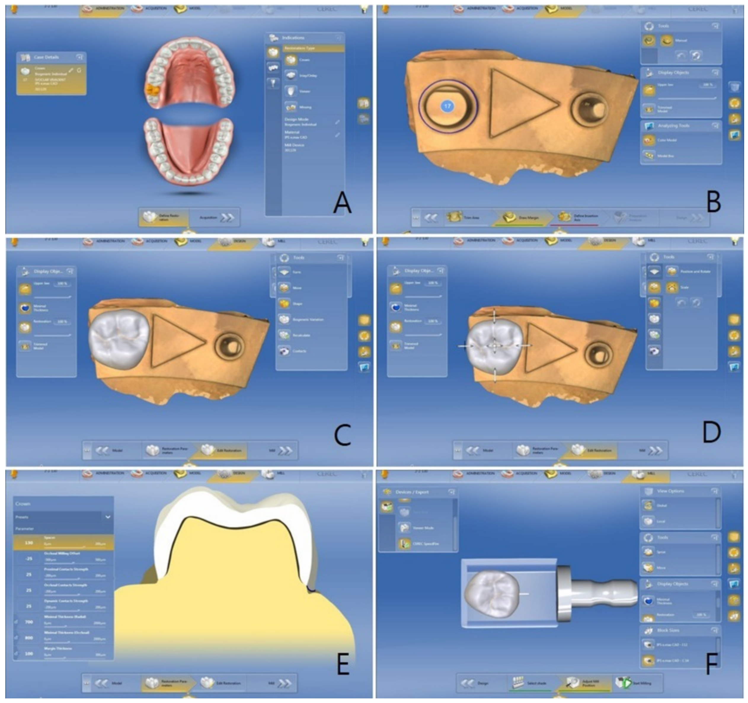
Using the CEREC software (CEREC S/W 4.4.4; Dentsply Sirona, York, PA, USA, 2017) the crown was designed as follows: the patient information was entered and then the teeth to be restored, the kinds of prostheses, and the materials to be used were selected (Figure 1A). Next, the inserting axes without margins or being undercut were then determined (Figure 1B). After the design of the crown was selected in the library (Figure 1C), the location and size of the crown were adjusted (Figure 1D). Next, the setting values of the following input variables were given (cement space, 80 µm; Figure 1E). At last, the location and size of the crown inside the lithium disilicate ceramic CAD block (IPS e.max CAD LT; Ivoclar Vivadent AG, Schaan, Liechtenstein, 2017) were checked using the CAM software prior to the fabrication of the crown (Figure 1F). The IPS e.max CAD block was processed using a CEREC MC XL milling device (Dentsply Sirona, Bensheim, Germany, 2017), and the milled crown was crystallized using a Programat P300 ceramic kiln (Ivoclar Vivadent AG, Schaan, Liechtenstein, 2017), as per the manufacturer’s instructions.
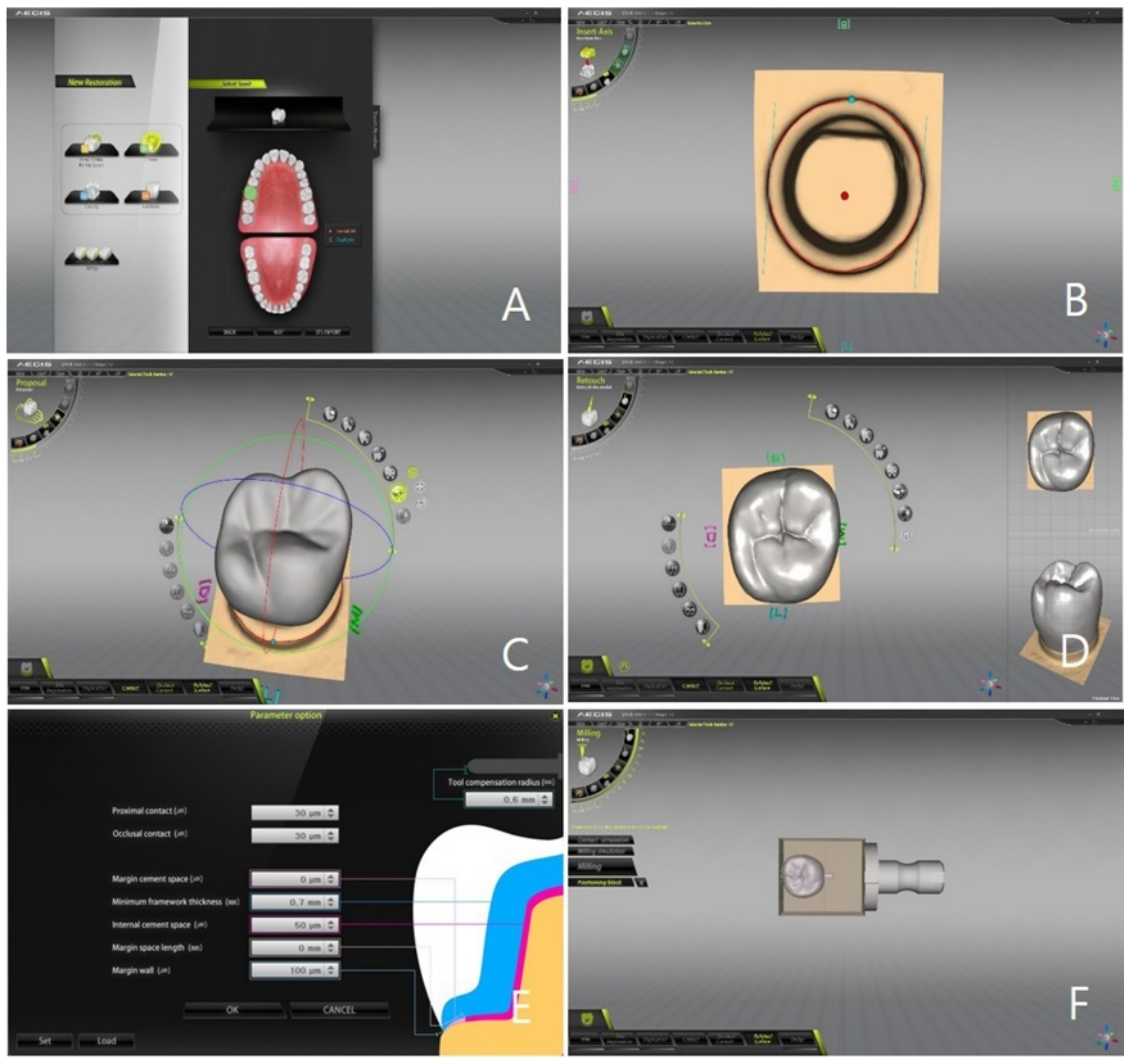
Regarding the EZIS software (EZIS VR 1.4.2.14; DDS, Seoul, Korea, 2017), the same procedure was performed to create the crown (Figure 2). The ceramic crown was fabricated from the lithium disilicate ceramic CAD block with an EZIS HM milling device (Digital Dentistry Solution, Seoul, Korea, 2017). It was then fired using the same procedure as with the CEREC system.
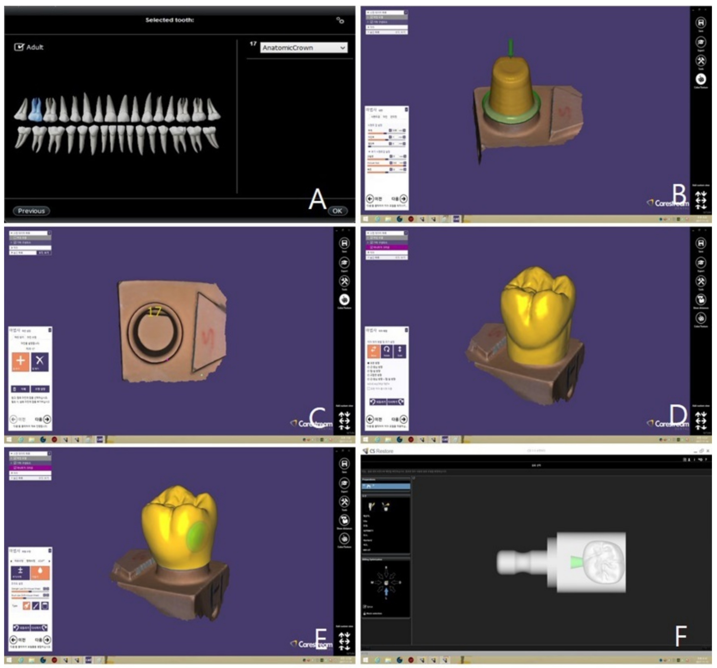
Regarding the Carestream system, the crown was designed unlike the other two systems described above; the steps in Figure 3A were carried out with the dental CAD software (Exocad Chairside; Exocad GmbH, Darmstadt, Germany, 2017). In addition, the steps in Figure 3B–E were conducted using the crown-design feature of dental CAD software (Exocad Chairside). In these steps, all input variables were identical to the two systems discussed above. At last, the size of the crown inside the block was checked and the location was adjusted using the CAM software (CS Restore; Carestream Dental, Atlanta, GA, USA; Figure 3F). Next, the ceramic crown was fabricated from an IPS e.max CAD block using a CS3000 milling device (Carestream Dental, Atlanta, GA, USA, 2017). The crystallization step was identical to that of the previous two systems.
The milling devices of the CEREC and EZIS systems, shown in Table 1, allow simultaneous processing of the inside and outside of the ceramic crown by the two milling burs. In contrast, the milling device of the Carestream system permitted milling of the inner and outer sides using one milling bur on both sides.
2.4. Three-Dimensional Analysis of the Marginal and Internal Fit
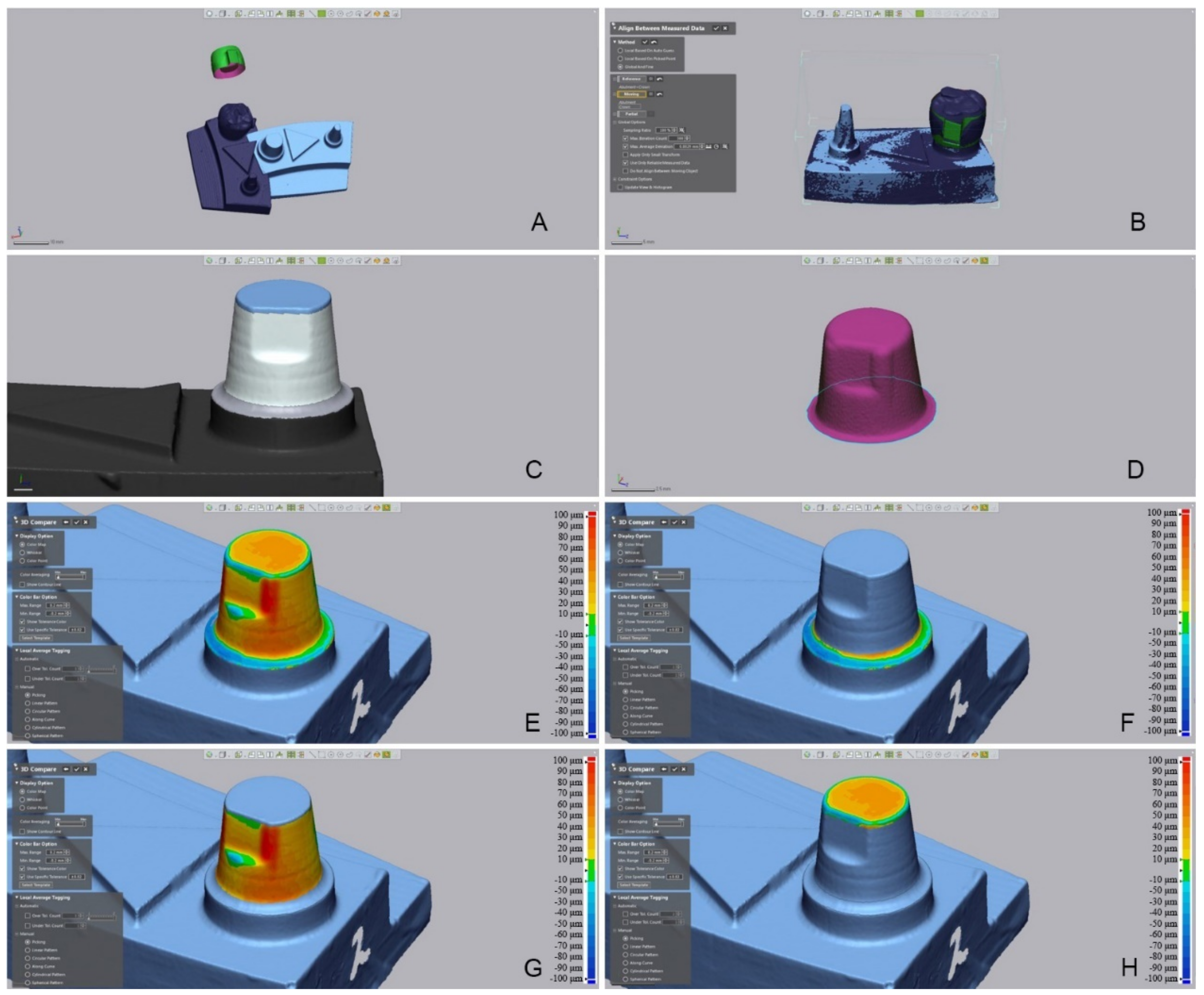
The triple-scan data were collected using the following procedure: the crown intaglio was scanned using a contact-type scanner (DS10; Renishaw plc., Gloucestershire, UK, 2017) and the data were stored in STL format (Figure 4A). The touch probe scanner uses a probe, which gently touches the surface, and is capable of rising and falling through 200 µm. The intaglio of the crown milled using the 1.0 mm milling burr was precisely scanned using a probe with a diameter of 0.5 mm. The touch probe was used to scan from the intaglio end of the crown to the end of the crown margin. The coordinates of about 20,000 points on the inner surface of the crown were recorded by the touch probe. Since the use of this method did not incur any errors caused by the optical characteristics of the object, it was ideal for scanning the intaglio surface of a lithium disilicate crown. In addition, the trueness could be analyzed precisely because of the excellent repeatability/reproducibility that was possible with this instrument.
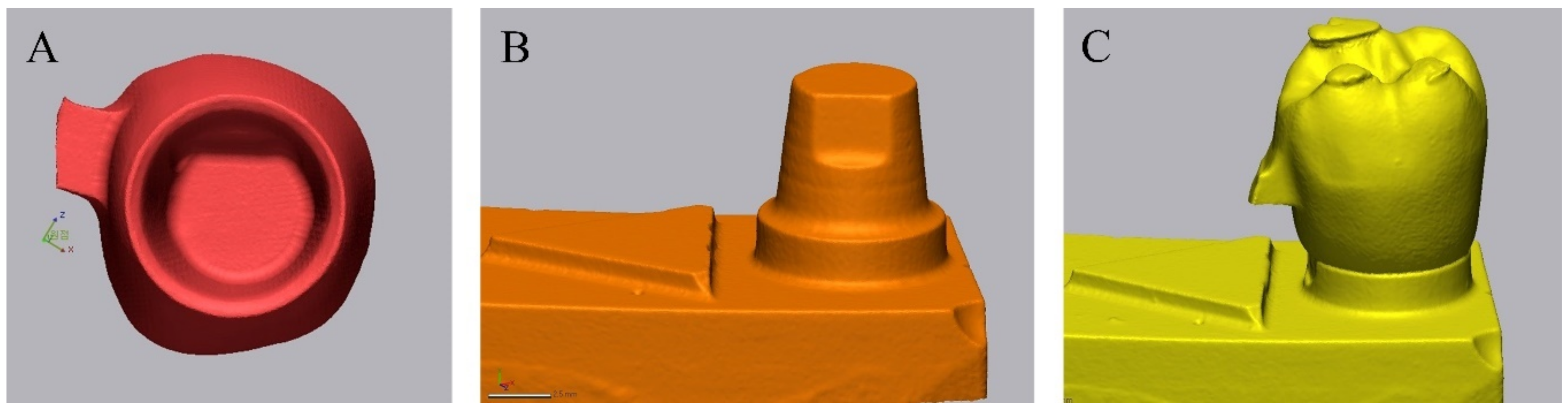
Next, the model of the abutment tooth was scanned with a dental optical scanner (Identica Hybrid; Medit, Seoul, Korea, 2017) and the data were stored in STL format (Figure 4B). The models were scanned according to the manufacturer’s recommendations without any special adjustment of the scanner. At last, the crown was installed at the clinically accurate location on the abutment tooth of the working model, scan powder (Snow Scan Powder; DK Mungyo, Seoul, Korea, 2017) was sprayed, and a scan was performed using an optical scanner (Figure 4C). A thin (approximately 1 μm) and uniform layer of scan powder was applied. The data related to Figure 4A–C were named “crown intaglio file,” “master die file,” and “adaptation file,” respectively.
These three files were opened in the 3D inspection software (Geomagic Control X; 3D Systems, Rock Hill, SC, USA, 2017; Figure 5A). To superimpose the crown intaglio file and master die file, the adaptation file was set as the reference data. An initial alignment was performed, followed by a best-fit alignment (Figure 5B). After the best-fit alignment, the adaptation file was deleted, and the master die and crown intaglio files were used as the reference and measurement data, respectively. Next, the inner and marginal gaps were measured. To perform 3D analysis of each region, the master die file was divided into cervical, axial, and occlusal regions (Figure 5C), while the outer surface was removed from the crown intaglio file on the basis of the margin line (Figure 5D). The 3D analysis was conducted with the entire inner side as its range (Figure 5E), as well as in each region of the inner side (Figure 5F–H).
The difference between the reference data and measured data was recorded as a root mean square (RMS) value. A greater RMS value meant greater error (i.e., a greater difference between the reference and the measured data). The RMS was calculated using the equation below.
where is the measuring point at k in the reference data, is the measuring point at k in the measured data, and n is the total number of measuring points per specimen.
2.5. Statistics
All measured data were analyzed using statistics software (IBM SPSS Statistics v23.0; IBM Corp, USA, 2017) (α = 0.05). First, the normal distribution of the data was examined through the Shapiro–Wilk test, and the data were found not to be normally distributed. Since the data were not normally distributed, non-parametric statistical methods were used. The differences among the systems and between the measured regions were evaluated using the Kruskal–Wallis test and a pairwise comparison as post-hoc tests (α = 0.05).
3. Results
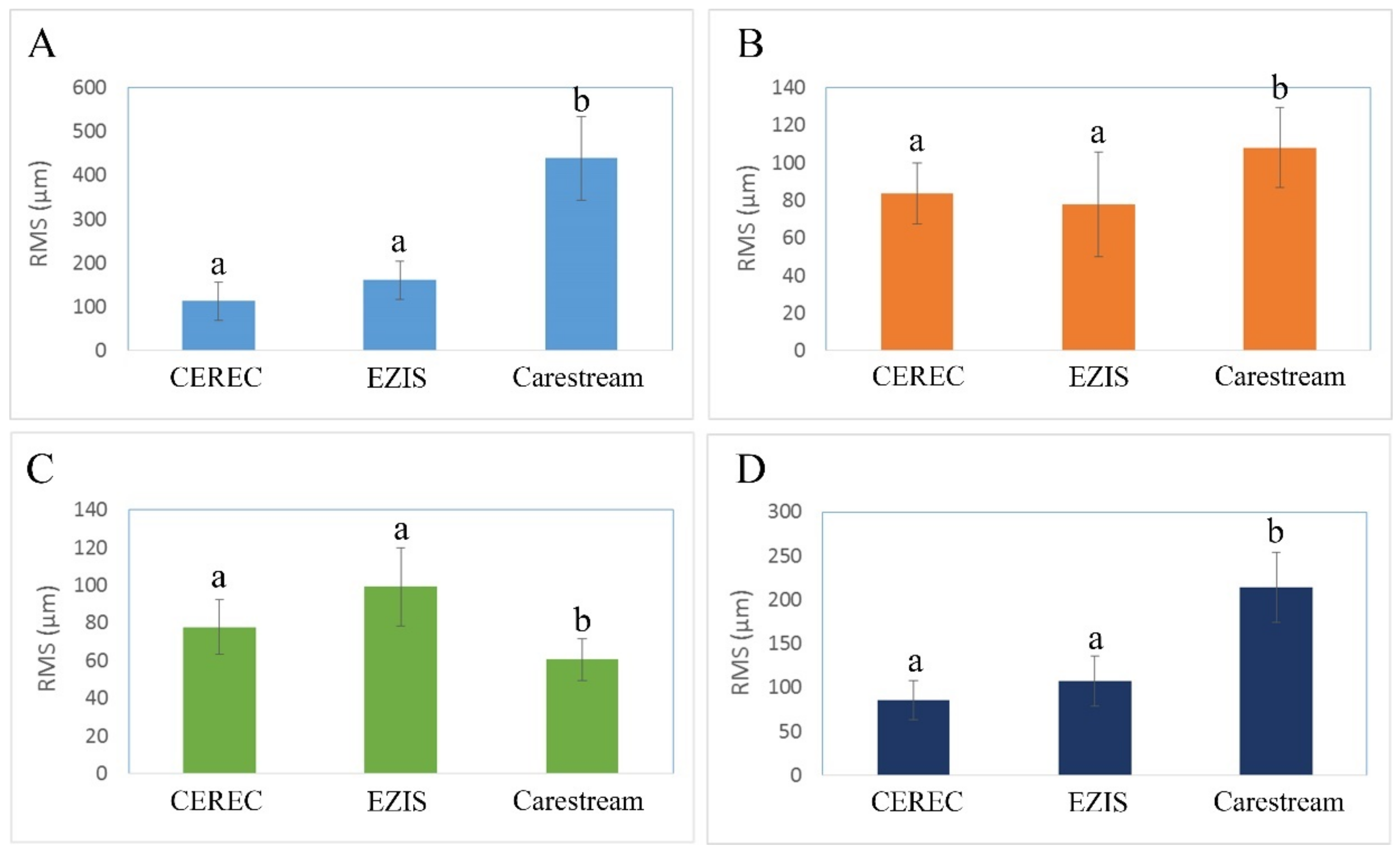
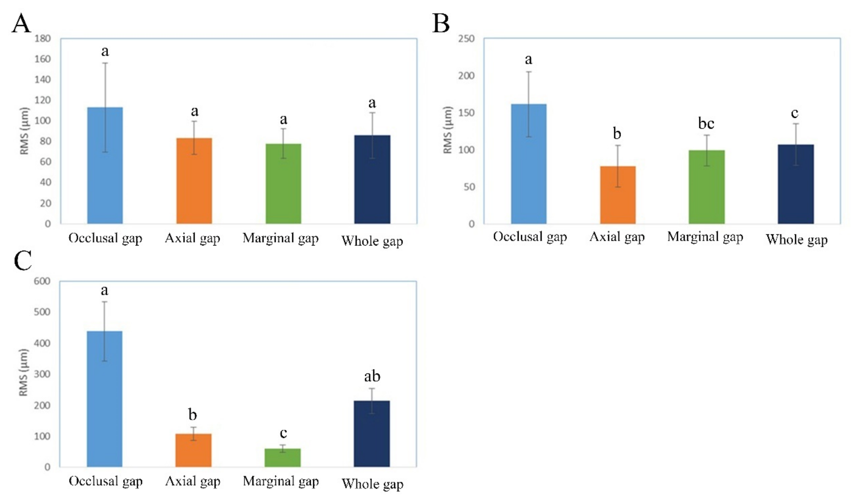
Figure 6 and Figure 7 illustrate the occlusal, axial, cervical, and whole gaps in the CEREC, EZIS, and Carestream systems. The occlusal gap was the smallest in the CEREC system (113.0 ± 43.4 µm), followed by the EZIS system (161.3 ± 43.5 µm), and the Carestream system (438.2 ± 96.3μm; p < 0.001); Figure 6). The axial gap was the smallest in the EZIS system (78.0 ± 27.8 µm), followed by CEREC system (83.4 ± 16.2 µm), and Carestream system (107.9 ± 21.2µm; p < 0.001; Figure 6). The marginal gap was the smallest value in the Carestream system (60.6 ± 11.2 µm), followed by the CEREC system (77.8 ± 14.5 µm) and EZIS system (99.3 ± 20.8 µm; p < 0.001; Figure 6). The whole gap was small in the order: the CEREC system (85.9 ± 22.1 µm), EZIS system (107.3 ± 28.1μm), and Carestream (214.0 ± 39.7 μm; p < 0.001; Figure 6).
In addition, we assessed the significance of each item (occlusal, axial, cervical, and whole gaps; Figure 7; p < 0.001) without the CEREC group. The CEREC system did not present a statistically significant difference among the four measured regions (Figure 7; p = 0.514). The EZIS system showed a statistically significant difference between the occlusal gap and the gaps of the other three regions (axial, cervical, and whole; Figure 6B; p < 0.001). Statistically significant differences were found between the occlusal gap and two other measured locations (axial and marginal gap) in the Carestream system (Figure 7; p < 0.001).
4. Discussion
One-day prosthesis treatment is a comprehensive dental treatment that is carried out in the dental clinic in the following sequence: (1) scanning of the dental shape using digital intraoral scanners without taking an impression; (2) designing prostheses using CAD software; and (3) fabricating prostheses using CAM. Same-day prosthesis treatment has more advantages than traditional prosthesis treatment, and it is, therefore, becoming more widespread. Many studies have compared various scanners and investigated the marginal and internal fit of prostheses fabricated using CAD/CAM systems [17,18,19,20,21,22,23,24]. However, few have compared different types of chairside CAD/CAM systems, and almost none have compared all-in-one type systems with combined-type systems. The all-in-one type system means that the device used in all processes from scanning to CAD/CAM is configured by one manufacturer. On the contrary, the combined-type system means that the device used in all processes by a combination of different manufacturers. In the present study, we used two all-in-one type systems (CEREC and EZIS) and one combined-type system (Carestream). With the all-in-one systems, the entire process from scanning to fabrication was performed within one construction based on a stable system wherein each component was optimized. However, the combined-type system required one system to be set by combining each component. This could be inconvenient because optimizing processes may need to be run in each step due to the system lacking a stable linkage between components. The following factors may influence the marginal and internal fit of ceramic crowns fabricated using CAD/CAM systems: the kind of prostheses [17,18], materials for fabrication [5,19], abutment tooth design [17], accuracy of the scanner [20,21,22,23], design software [24], assigned input variables [20], and accuracy of the processing equipment [8,19,24]. In this experiment, the accuracy of the scanners, the function of the design software, the assigned input variables, and the accuracy of the processing equipment may have influenced the marginal and internal fit of the ceramic crowns.
The Omnicam of the CEREC system is the first intraoral scanner that does not require use of titanium dioxide powder; it obtains images with confocal laser imaging-based rendering instead [25]. Likewise, the CS3500 of the Carestream system does not require the use of powder, whereas the PO of the EZIS system does, obtaining the image through triangulation technology-based stitching [25]. One study found that the trueness of the Omnicam was 13.8 ± 1.4 µm [26], whereas another showed that the trueness of the Omnicam and CS3500 were 31.8 ± 5.4 µm and 26.7 ± 3.5 µm, respectively [27]. In addition, the trueness of the EZIS system’s PO is approximately 20 µm, according to the manufacturer. Recently, intraoral scanners with higher performance and quality have been developed and have been widely distributed, contributing to diversity in the types of chairside systems available and greater accuracy in the fabrication of prostheses. Lang et al. presented a marginal gap of <120 µm in a crown fabricated using a CAD/CAM system; they reported that this difference may be due to the conversion of the digital model into a prosthesis [28]. Syrek et al. stated that a ceramic crown (IPS e.max CAD; Ivoclar Vivadent AG, Schaan, Liechtenstein) showed a marginal gap of 74–76 µm, which is within the clinically acceptable range [29].
In this study, the cement space appropriate to each system was determined before the main experiment was conducted. In many previous studies involving prostheses fabricated using CAD/CAM systems, marginal and internal fit was evaluated with no detailed descriptions of the input variables. Similar to cast prostheses, whose accuracy depends on the practitioner’s proficiency and on materials, CAD/CAM prostheses yield different results due to: (1) optimization differences between the equipment and software; (2) the condition of the tools (scanner tip and milling tool); (3) compensation; and (4) the proficiency of a practitioner. Hence, the present study aimed to identify the optimum input variables in the condition setting step so that the experiment would be reproducible. All scanned data were analyzed using the triple-scan method [16,30]. This 3D measurement was validated in the preparatory experiment, which was conducted prior to the main experiment; it has also been used in numerous studies [31]. While the crowns fabricated using the CEREC and Carestream systems presented marginal gaps that were <90 µm wide, the crown fabricated using the EZIS system presented a gap of about 10 µm wider. The maximum clinically acceptable marginal gap has not yet been agreed upon; however, the literature suggests a value between 50 µm and 200 µm. More specifically, the 100–120 µm range reported by McLean et al. has frequently been used [31]. Boeddinghaus et al. recently conducted a study comparing the intraoral and model scanners [23]. They reported that the marginal gap of ceramic prostheses fabricated using the Omnicam was 149 µm [23]. In the present study, the marginal gap of a ceramic crown fabricated using three kinds of chairside CAD/CAM systems was within the clinically acceptable range.
The CEREC system had the narrowest occlusal gap; i.e., 113.0 ± 43.4 µm, followed by the EZIS system; i.e., 161.3 ± 43.5 µm. However, the Carestream system presented a gap of 438.2 ± 96.3 µm, which was much larger than the gaps for the other two systems. This could be attributed to the difference in accuracy between the milling equipment and intraoral scanner. Further research is needed on using the newly launched intraoral scanner and milling unit in the Carestream system.
There were limitations in the present in vitro study. The scanning process did not reflect the clinical environment (wet environment, ambient light, etc.). Further clinical studies are required in the future. In addition, additional studies on fixed prostheses for multiple units are also needed.
5. Conclusions
Different chairside CAD/CAM workflows affected the marginal and internal fits of the ceramic crown. All three chairside CAD/CAM systems were judged to be capable of fabricating prostheses that are clinically acceptable, because the marginal gap, which is the most important element in the marginal and internal fit of prostheses, was recorded to be below 100 µm for each all three systems.
Author Contributions
Conceptualization, K.S.; Methodology, K.S.; Validation, K.-B.L.; Formal Analysis, K.S.; Investigation, K.S.; Data Curation, K.-B.L.; Writing—Original Draft, K.S.; Visualization, K.S.; Supervision, K.-B.L.; Project Administration, K.-B.L. All authors have read and agreed to the published version of the manuscript.
Funding
This work was supported by the Industrial Strategic Technology Development Program (10062635, New hybrid milling machine with a resolution of less than 10 µm development, using open CAD/CAM S/W integrated platforms for one-day prosthetic treatment of 3D smart medical care system) funded by the Ministry of Trade, Industry and Energy (MOTIE, Korea). This work was by supported Industrial Infrastructure Program of Laser Industry Support (Grant N0000598) funded By the Ministry of Trade, Industry & Energy (MOTIE, Korea).
Institutional Review Board Statement
Not applicable.
Informed Consent Statement
Not applicable.
Data Availability Statement
Data is contained within the article.
Acknowledgments
The authors thank the researchers of the Advanced Dental Device Development Institute, Kyungpook National University for their time and contributions to the study.
Conflicts of Interest
The authors declare no conflict of interest. The funders had no role in the design of the study; in the collection, analyses, or interpretation of the data; in the writing of the manuscript, or in the decision to publish the results.
References
- Shimizu, S.; Shinya, A.; Kuroda, S.; Gomi, H. The accuracy of the CAD system using intraoral and extraoral scanners for designing of fixed dental prostheses. Dent. Mater. J. 2017, 36, 402–407. [Google Scholar] [CrossRef] [Green Version]
- Emir, F.; Piskin, B.; Sipahi, C. Effect of dental technician disparities on the 3-dimensional accuracy of definitive casts. J. Prosthet. Dent. 2017, 117, 410–418. [Google Scholar] [CrossRef] [PubMed]
- Su, T.S.; Jian, S. Intraoral digital impression technique: A review. J. Prosthodont. 2015, 24, 313–321. [Google Scholar]
- Muianga, M.I.D.S. Data Capture Stabilising Device for the CEREC Cad/Cam Chairside Camera. Ph.D. Thesis, University of the Witwatersrand, Johanesburg, South Africa, October 2009. [Google Scholar]
- Anadioti, E.; Aquilino, S.A.; Gratton, D.G.; Holloway, J.A.; Denry, I.; Thomas, G.W.; Qian, F. 3D and 2D marginal fit of pressed and CAD/CAM lithium disilicate crowns made from digital and conventional impressions. J. Prosthodont. 2014, 23, 610–617. [Google Scholar] [CrossRef] [PubMed]
- Paşalı, B.; Saraç, D.; Kaleli, N.; Saraç, Y.S. Evaluation of marginal fit of single implant-supported metal-ceramic crowns prepared by using presintered metal blocks. J. Prosthet. Dent. 2018, 119, 257–262. [Google Scholar] [CrossRef] [PubMed]
- Sakornwimon, N.; Leevailoj, C. Clinical marginal fit of zirconia crowns and patients’ preferences for impression techniques using intraoral digital scanner versus polyvinyl siloxane material. J. Prosthet. Dent. 2017, 118, 386–391. [Google Scholar] [CrossRef] [PubMed]
- Kim, J.H.; Jeong, J.H.; Lee, J.H.; Cho, H.W. Fit of lithium disilicate crowns fabricated from conventional and digital impressions assessed with micro-CT. J. Prosthet. Dent. 2016, 116, 551–557. [Google Scholar] [CrossRef] [PubMed]
- Bae, S.Y.; Park, J.Y.; Jeong, I.D.; Kim, H.Y.; Kim, J.H.; Kim, W.C. Three-dimensional analysis of marginal and internal fit of copings fabricated with polyetherketoneketone (PEKK) and zirconia. J. Prosthodont. Res. 2017, 61, 106–112. [Google Scholar] [CrossRef]
- Lalande, D.; Hodd, J.A.; Brousseau, J.S.; Ramos, V.; Dunham, D.; Rueggeberg, F. Marginal discrepancy dimensions of single unit metal crowns fabricated by using CAD-CAM–milled acrylate resin polymer blocks or a conventional waxing technique. J. Prosthet. Dent. 2018, 119, 948–953. [Google Scholar] [CrossRef]
- Colpani, J.T.; Borba, M.; della Bona, Á. Evaluation of marginal and internal fit of ceramic crown copings. Dent. Mater. 2013, 29, 174–180. [Google Scholar] [CrossRef]
- Lee, K.B.; Park, C.W.; Kim, K.H.; Kwon, T.Y. Marginal and internal fit of all-ceramic crowns fabricated with two different CAD/CAM systems. Dent. Mater. J. 2008, 27, 422–426. [Google Scholar] [CrossRef] [PubMed] [Green Version]
- Kim, K.B.; Jung, J.K.; Kim, J.H. Accuracy of Digital Impression Made from Different Elastomeric Impression Materials: Three-Dimensional Superimpositional Analysis. J. Dent. Hyg. Sci. 2014, 14, 94–100. [Google Scholar]
- Dahl, B.E.; Rønold, H.J.; Dahl, J.E. Internal fit of single crowns produced by CAD-CAM and lost-wax metal casting technique assessed by the triple-scan protocol. J. Prosthet. Dent. 2017, 117, 400–404. [Google Scholar] [CrossRef] [PubMed]
- Lee, H.; Kim, H.S.; Noh, K.; Paek, J.; Pae, A. A simplified method for evaluating the 3-dimensional cement space of dental prostheses by using a digital scanner. J. Prosthet. Dent. 2017, 5, 584–586. [Google Scholar] [CrossRef]
- Holst, S.; Karl, M.; Wichmann, M.; Matta, R.E.T. A new triple-scan protocol for 3D fit assessment of dental restorations. Quintessence Int. 2011, 42, 651–657. [Google Scholar]
- Schaefer, O.; Decker, M.; Wittstock, F.; Kuepper, H.; Guentsch, A. Impact of digital impression techniques on the adaption of ceramic partial crowns in vitro. J. Dent. 2014, 42, 677–683. [Google Scholar] [CrossRef]
- Akın, A.; Toksavul, S.; Toman, M. Clinical Marginal and Internal Adaptation of Maxillary Anterior Single All-Ceramic Crowns and 2-year Randomized Controlled Clinical Trial. J. Prosthodont. 2015, 24, 345–350. [Google Scholar] [CrossRef]
- Anadioti, E.; Aquilino, S.A.; Gratton, D.G.; Holloway, J.A.; Denry, I.L.; Thomas, G.W.; Qian, F. Internal fit of pressed and computer-aided design/computer-aided manufacturing ceramic crowns made from digital and conventional impressions. J. Prosthet. Dent. 2015, 113, 304–309. [Google Scholar] [CrossRef]
- Mously, H.A.; Finkelman, M.; Zandparsa, R.; Hirayama, H. Marginal and internal adaptation of ceramic crown restorations fabricated with CAD/CAM technology and the heat-press technique. J. Prosthet. Dent. 2014, 112, 249–256. [Google Scholar] [CrossRef]
- Abdel-Azim, T.; Rogers, K.; Elathamna, E.; Zandinejad, A.; Metz, M.; Morton, D. Comparison of the marginal fit of lithium disilicate crowns fabricated with CAD/CAM technology by using conventional impressions and two intraoral digital scanners. J. Prosthet. Dent. 2015, 114, 554–559. [Google Scholar] [CrossRef]
- Alfaro, D.P.; Ruse, N.D.; Carvalho, R.M.; Wyatt, C.C. Assessment of the Internal Fit of Lithium Disilicate Crowns Using Micro-CT. J. Prosthodont. 2015, 24, 381–386. [Google Scholar] [CrossRef] [PubMed]
- Boeddinghaus, M.; Breloer, E.S.; Rehmann, P.; Wöstmann, B. Accuracy of single-tooth restorations based on intraoral digital and conventional impressions in patients. Clin. Oral Investig. 2015, 19, 2027–2034. [Google Scholar] [CrossRef] [PubMed]
- Tidehag, P.; Ottosson, K.; Sjögren, G. Accuracy of ceramic restorations made using an in-office optical scanning technique: An in vitro study. Oper. Dent. 2014, 39, 308–316. [Google Scholar] [CrossRef] [PubMed] [Green Version]
- Uhm, S.H.; Kim, J.H.; Jiang, H.B.; Woo, C.W.; Chang, M.; Kim, K.N.; Oh, S. Evaluation of the accuracy and precision of four intraoral scanners with 70% reduced inlay and four-unit bridge models of international standard. Dent. Mater. J. 2017, 36, 27–34. [Google Scholar] [CrossRef] [Green Version]
- Lee, J.J.; Jeong, I.D.; Park, J.Y.; Jeon, J.H.; Kim, J.H.; Kim, W.C. Accuracy of single-abutment digital cast obtained using intraoral and cast scanners. J. Prosthet. Dent. 2017, 117, 253–259. [Google Scholar] [CrossRef]
- Kim, J.E.; Amelya, A.; Shin, Y.; Shim, J.S. Accuracy of intraoral digital impressions using an artificial landmark. J. Prosthet. Dent. 2017, 117, 755–761. [Google Scholar] [CrossRef]
- Lang, N.P.; Kiel, R.A.; Anderhalden, K. Clinical and microbiological effects of subgingival restorations with overhanging or clinically perfect margins. J. Clin. Periodontol. 1983, 10, 563–578. [Google Scholar] [CrossRef]
- Syrek, A.; Reich, G.; Ranftl, D.; Klein, C.; Cerny, B.; Brodesser, J. Clinical evaluation of all-ceramic crowns fabricated from intraoral digital impressions based on the principle of active wavefront sampling. J. Dent. 2010, 38, 553–559. [Google Scholar] [CrossRef]
- Son, K.; Lee, S.; Kang, S.H.; Park, J.; Lee, K.-B.; Jeon, M.; Yun, B.-J. A Comparison Study of Marginal and Internal Fit Assessment Methods for Fixed Dental Prostheses. J. Clin. Med. 2019, 8, 785. [Google Scholar] [CrossRef] [Green Version]
- McLean, J.W.; von Fraunhofer, J.A. The estimation of cement film thickness by an in vivo technique. Br. Dent. J. 1971, 131, 107–111. [Google Scholar] [CrossRef]
Figure 1.
Crown design process using a computer-aided design and manufacturing software with the CEREC system. (A) Definition of a prosthesis (tooth selection, material selection, etc.); (B) margin setting; (C) design suggestions; (D) design modification of the prosthesis (size, position, etc.); (E) parameter setting; (F) confirmation of the size and position in the block for milling.

Figure 2.
Crown design process using computer-aided design and manufacturing software with the EZIS system. (A) Selection of teeth to be restored; (B) design of margins and insertion axes; (C) selected crown from the proposed library; (D) crown modeling; (E) numerical values as parameters; (F) crown alignment for milling.

Figure 3.
Crown design process using computer-aided design and manufacturing software with the Carestream system. (A) Selection of teeth to be restored; (B) numerical values as parameters (C) design of margins and insertion axes; (D) crown selection from the proposed library; (E) crown modeling; (F) crown alignment for milling.

Figure 4.
Triple scanning. (A) Crown intaglio; (B) master die; (C) adaptation.

Figure 5.
Marginal and internal fit measurement using triple-scan data. (A) Import of three scan files; (B) initial and best-fit alignment; (C) segmentation of the measurement region; (D) elimination of crown data beyond the margin; (E) measurement of overall internal space; (F) 3-dimensional comparison in the cervical section; (G) 3-dimensional comparison in the axial section; (H) 3-dimensional comparison in the occlusal section.

Figure 6.
Marginal and internal fit comparisons within each measurement region. (A) Occlusal gap; (B) axial gap: (C) marginal gap; (D) whole gap. Values with the same letter (a, b) are not statistically different based on a pairwise comparison test (p < 0.05).
Figure 6.
Marginal and internal fit comparisons within each measurement region. (A) Occlusal gap; (B) axial gap: (C) marginal gap; (D) whole gap. Values with the same letter (a, b) are not statistically different based on a pairwise comparison test (p < 0.05).

Figure 7.
Marginal and internal fit comparison within each group. (A) CEREC system; (B) EZIS system; (C) Carestream system. Values with the same letter (a, b, c) are not statistically different based on a pairwise comparison test (p < 0.05).
Figure 7.
Marginal and internal fit comparison within each group. (A) CEREC system; (B) EZIS system; (C) Carestream system. Values with the same letter (a, b, c) are not statistically different based on a pairwise comparison test (p < 0.05).


Table 1.
Features of each milling machine according to the manufacturer.
| CEREC MC XL | EZIS HM | CS 3000 | |
|---|---|---|---|
| Milling precision | ±25 µm | ±10 µm | ±25 µm |
| Indication | Complete spectrum of chairside and practice lab applications | Ideal for single-tooth restorations | Ideal for single-tooth restorations |
| Milling time | 4–12 min/unit | 15 min/unit | 15 min/unit |
| Material Compatibility | Zirconia, Wax, PMMA, Ceramics, Resin, CoCr | Glass ceramic, Lithium disilicate, Zirconia, Hybrid materials, PMMA, Modeling wax | Compatible with all-ceramic and resin-based materials |
| Number of Axes | 5 | 4 | 4 |
| Spindle speed | Not Available | Max. 63,000 rpm | Max. 60,000 rpm |
Publisher’s Note: MDPI stays neutral with regard to jurisdictional claims in published maps and institutional affiliations. |
© 2021 by the authors. Licensee MDPI, Basel, Switzerland. This article is an open access article distributed under the terms and conditions of the Creative Commons Attribution (CC BY) license (http://creativecommons.org/licenses/by/4.0/).
Share and Cite
MDPI and ACS Style
Son, K.; Lee, K.-B. Marginal and Internal Fit of Ceramic Prostheses Fabricated from Different Chairside CAD/CAM Systems: An In Vitro Study. Appl. Sci. 2021, 11, 857. https://doi.org/10.3390/app11020857
AMA Style
Son K, Lee K-B. Marginal and Internal Fit of Ceramic Prostheses Fabricated from Different Chairside CAD/CAM Systems: An In Vitro Study. Applied Sciences. 2021; 11(2):857. https://doi.org/10.3390/app11020857
Chicago/Turabian StyleSon, Keunbada, and Kyu-Bok Lee. 2021. "Marginal and Internal Fit of Ceramic Prostheses Fabricated from Different Chairside CAD/CAM Systems: An In Vitro Study" Applied Sciences 11, no. 2: 857. https://doi.org/10.3390/app11020857
Note that from the first issue of 2016, this journal uses article numbers instead of page numbers. See further details here.