Article

Optimal Design of a Hydrolysis Sugar Membrane Purification System Using a Superstructure-Based Approach

1
Green Energy & Environment Research Laboratories, Industrial Technology Research Institute, Hsinchu 310, Taiwan
2
Department of Chemical Engineering and Biotechnology, National Taipei University of Technology, 1, Sec. 3, Zhongxiao E. Road, Taipei 10608, Taiwan
3
Research Center of Energy Conservation for New Generation of Residential, Commercial, and Industrial Sectors, National Taipei University of Technology, 1, Sec. 3, Zhongxiao E. Road, Taipei 10608, Taiwan
*
Author to whom correspondence should be addressed.
Processes 2021, 9(1), 168; https://doi.org/10.3390/pr9010168
Submission received: 11 December 2020 / Revised: 8 January 2021 / Accepted: 12 January 2021 / Published: 18 January 2021
(This article belongs to the Special Issue Multi-Period Optimization of Sustainable Energy Systems)

Abstract

:
As an alternative to gasoline, bioethanol can be produced from lignocellulosic biomass through hydrolysis using an ionic solution containing zinc chloride (ZnCl2). This method allows for a high yield of glucose from lignocellulose, but entails the removal of ZnCl2 from the hydrolysate using multiple nanofiltration membranes before the fermentation of glucose. This paper presents a mathematical technique for designing such a multistage membrane separation system. The optimization model for the synthesis of membrane networks is based on a superstructure with all feasible interconnections between the membrane units, and consists of mass balances, logical constraints and product specifications. A case study of the separation of a bagasse hydrolysis solution is used to demonstrate the application of the proposed model. Results show that using both types of nanofiltration membranes allows higher ZnCl2 removal ratios at each membrane unit, hence a decrease in the number of membrane units required and a reduction of about 35% in capital cost compared to the cases in which only one membrane type is used. Further analysis is performed to examine the effect of membrane performance on the economics of the separation system.

1. Introduction

With declining petroleum resources and the pursuit of clean energy, researchers have paid more attention to developing efficient technology for alternative fuels. Biomass-derived sugars are considered a crucial raw material for liquid biofuel production through biological and chemical conversion. To that end, conventional sugar crops may not be preferred due to the competition with food uses. Alternatively, lignocellulosic biomass (e.g., energy crops, agricultural waste and forest residues) can be a good source of sugars. Lignocellulose is one of the most abundant plant-based materials on earth, amounting to approximately 200 billion metric tons annually [1]. Technological advancements in converting lignocellulosic biomass to sugars for biofuel production are expected to provide a promising solution to energy autonomy.
Lignocellulosic biomass consists of complicated carbohydrates with three basic polymers: hemicellulose, cellulose and lignin. Researchers at the National Renewable Energy Laboratory (NREL) of the U.S. Department of Energy have established five conversion technology platforms for base chemicals [2]. Among those, the sugar platform is the most promising process for the production of alternative fuels (e.g., ethanol) and other chemicals. Traditional lignocellulose hydrolysis technology can be divided into acid hydrolysis and enzyme hydrolysis. The latter is time-consuming and requires suitably adjusted conditions for bacteria to survive. Acid hydrolysis can be further divided into concentrated acid hydrolysis and diluted acid hydrolysis. The former usually uses sulfuric acid with a concentration of 30–70%. At lower temperatures, the cellulose can be completely dissolved and converted to oligosaccharides, which can then be hydrolyzed to glucose with a yield of up to 90%. However, the main drawbacks of the hydrolysis of cellulose using concentrated sulfuric acid are the high cost of anticorrosive devices and the necessity of recycling used acid to avoid corrosion and environmental pollution. These factors limit the application of this method.
The Purdue Research Foundation patented the hydrolysis of cellulose to glucose using zinc chloride (ZnCl2) [3]. More recently, the Industrial Technology Research Institute (ITRI) developed an ionic ZnCl2 solution to improve the yield of converting cellulose to glucose. This ionic solution is much cheaper than conventional ionic liquids, and can achieve a more than 90% high yield of glucose from lignocellulosic biomass [4]. However, the resulting glucose product stream has a high concentration of ZnCl2, which needs to be removed before the fermentation of glucose. The separation of glucose and ZnCl2 thus became an important issue.
Purification of reducing sugars after ionic-solution hydrolysis is considered a critical step of the entire bioethanol production process, because the separation of the salt from glucose is often expensive and may encounter contamination from solvent extraction. The ITRI has studied the separation of high-concentration ZnCl2 from the hydrolysis sugar product by nanofiltration (NF) and proven the capability of this approach [5]. The separation performance of NF membranes is between that of ultrafiltration (UF) and reverse osmosis (RO) membranes; however, NF membranes have a wider range of applications than conventional membranes [6]. So far, the commercial application of NF membranes is mainly in desalination, especially in food processes. Some previous studies [7,8,9,10] have focused on the effects of solute charge, pH and temperature on the retention effect of NF membranes.
With many results, NF has proven itself to be a good candidate for sugar/salt separation [5]. However, the required product specifications cannot be met with a single membrane; a number of membrane units are needed to achieve the desired effect. This presents the problem of designing an NF separation system featuring a network of membrane units, with some arranged in series and some in parallel. Moreover, although simulation is useful in assessing the performance of a given network configuration, optimization is needed to find the optimal network configuration and determine the performance targets in terms of capital cost, water consumption and the number of membrane units. This work aims to develop an optimization approach to the design of NF separation systems.
Superstructure optimization is a powerful tool for process design, enabling systematic and integrated analysis of alternative structures [11]. Superstructure-based approaches have been applied to the synthesis of various membrane separation networks. El-Halwagi [12] introduced the problem of synthesizing RO networks and developed a mixed integer nonlinear programming (MINLP) model for desalination and dephenolization applications. Voros et al. [13,14] proposed an alternative superstructure resulting in an easier-to-tackle nonlinear programming (NLP) model. Lu et al. [15] presented a simplified superstructure and a pressure vessel model for the design of multistage RO systems for seawater desalination under different feed concentrations and product specifications. Lu et al. [16] studied an RO-based seawater desalination system for producing freshwater of multiple concentration levels. A numerical model describing the membrane transport of RO in spiral-wound modules was introduced by Du et al. [17]. Optimization approaches to the design of RO networks under boron constraints were also proposed [18,19]. Alnouri and Linke [20] proposed compact superstructure representations and a structured synthesis strategy to facilitate the identification of optimal membrane networks. Abejón et al. [21] optimized an RO network for the ultrapurification of hydrogen peroxide for electronic applications. Chauhan et al. [22] developed a superstructure-based optimization approach for hybrid seawater RO-NF membrane desalination and salt production. More recently, Parra et al. [23] proposed the use of metamodels to speed up the solution of the nonlinear RO network optimization problem.
Apart from desalination, membrane networks are also designed for gas separation. Qi and Henson [24] developed an MINLP model for spiral-wound membrane systems for the separation of CO2/CH4 mixtures in natural gas treatment and enhanced oil recovery. Kookos [25] considered countercurrent hollow-fiber membrane modules and presented a targeting approach to optimize the membrane material for the production of nitrogen or oxygen enriched air. Various flow patterns (cross, countercurrent and concurrent) and all possible membrane network configurations are embedded in the superstructure of Uppaluri et al. [26]. These authors later presented a targeting-design approach to optimize the pressure and network configuration of gas separation membranes [27]. Arias et al. [28] presented an NLP model to determine the optimal number of membrane stages and operating conditions for CO2 capture in coal-fired power plants. Shafiee et al. [29] presented an automated flowsheet synthesis method to optimize a hybrid membrane/cryogenic CO2 capture process. Ramírez-Santos et al. [30] presented a global optimization approach for multistage membrane separation systems for capturing CO2 from blast furnace gas. Lee et al. [31] developed and applied an optimization framework to the design of multistage membrane processes for CO2 capture from flue gas.
Superstructure-based approaches were also developed for the synthesis of thermal membrane distillation networks [32] and bio-separation networks [33]. More recently, Baaqeel and El-Halwagi [34] considered the integration of multiple effect distillation and membrane distillation for multi-period capacity planning in desalination networks. Oke et al. [35] considered the use of thermally driven membrane distillation to purify flowback wastewater for fracturing water reuse. Mores et al. [36] carried out an optimization study of membrane-based separation systems with up to four stages for CO2 capture from flue gas of power plants. Tao et al. [37] carried out an integrated design of multi-stage membrane separation systems with uncertain concentrations and flowrates, proposing three landfill gas purification strategies. Martín-Hernández et al. [38] developed a superstructure model integrating amine absorption, pressure swing adsorption and membrane separation to determine the optimal process and operating conditions for biomethane production. However, as yet there was no such approach developed for the separation of hydrolysis solutions in bioethanol production. Chemical hydrolysis using a ZnCl2 solution has been recognized as a promising method for converting lignocellulosic biomass to glucose [4]. The subsequent removal of ZnCl2 from the hydrolysate using NF membranes (for the hydrolysis sugar solution to be fermented) is critical to the economic viability of bioethanol production through chemical hydrolysis [5]. In this paper, a mathematical model is developed for the design and optimization of NF membrane networks for sugar/salt separation. The optimization model is based on a generic superstructure that embeds all possible interconnections between the membrane units, and is useful in determining the optimal network configuration of the membrane separation system. The rest of the paper is organized as follows. A formal problem statement is given in Section 2. The model formulation is presented in Section 3. A case study is then presented in Section 4 to illustrate the proposed approach. Finally, conclusions and prospects for future work are given in Section 5.

2. Problem Statement

The problem addressed in this paper can be formally stated as follows.
  • Given a feed mixture containing a set of components i I . The flowrate of the feed and the concentrations of the components are known.
  • A set of membrane units j J are used to separate the feed mixture. The performance data for the membranes (i.e., cut fractions and recoveries/removal ratios) are specified.
  • In this work, NF membranes are used to separate ZnCl2 and glucose in a bagasse hydrolysis solution. The objective is to synthesize an optimal NF membrane network that achieves the required product specifications at the minimum capital cost.

3. Model Formulation

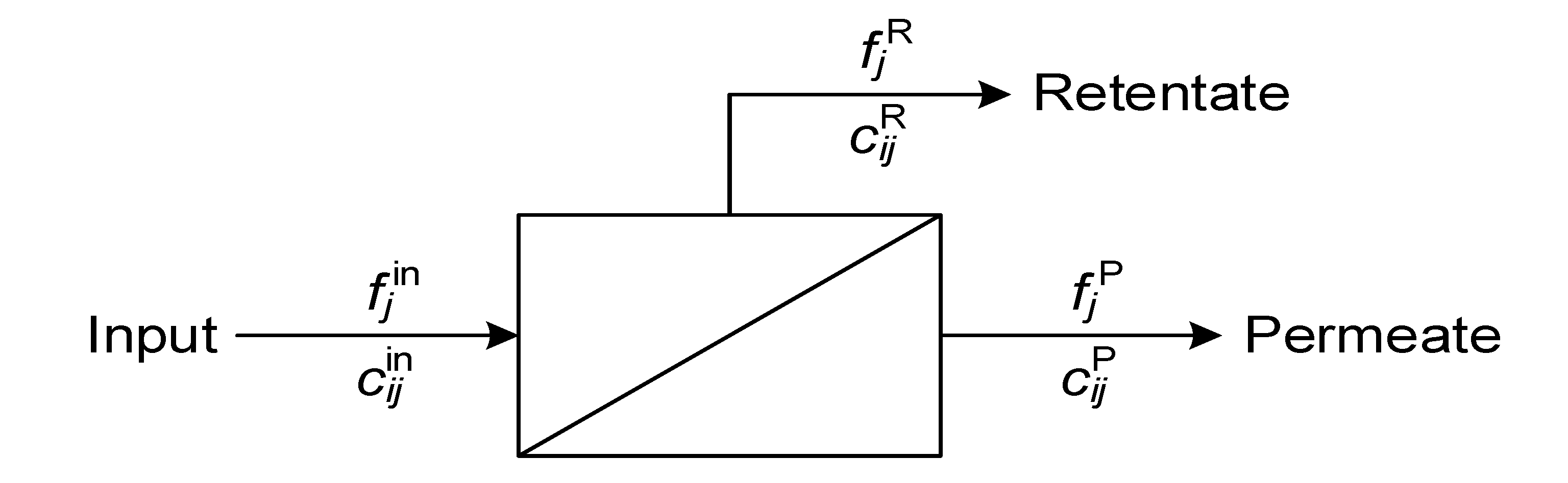
Figure 1 shows a schematic diagram of an NF membrane unit, where the inlet stream is separated into a retentate and a permeate. Equations (1) and (2) describe the flowrate and component balances, respectively.
f j in = f j R + f j P j J
f j in c i j in = f j R c i j R + f j P c i j P       i I , j J
where f j in , f j R and f j P are the flowrates of the inlet stream, retentate and permeate of unit j, respectively; c i j in , c i j R and c i j P are the respective concentrations of component i. The cut fraction ( θ j ) and the recovery ( r i j ) are defined as in Equations (3) and (4), respectively. The recovery of the components depends on the membrane type.
f j R = θ j f j in j J
f j R c i j R = f j in c i j in r i j       i I , j J
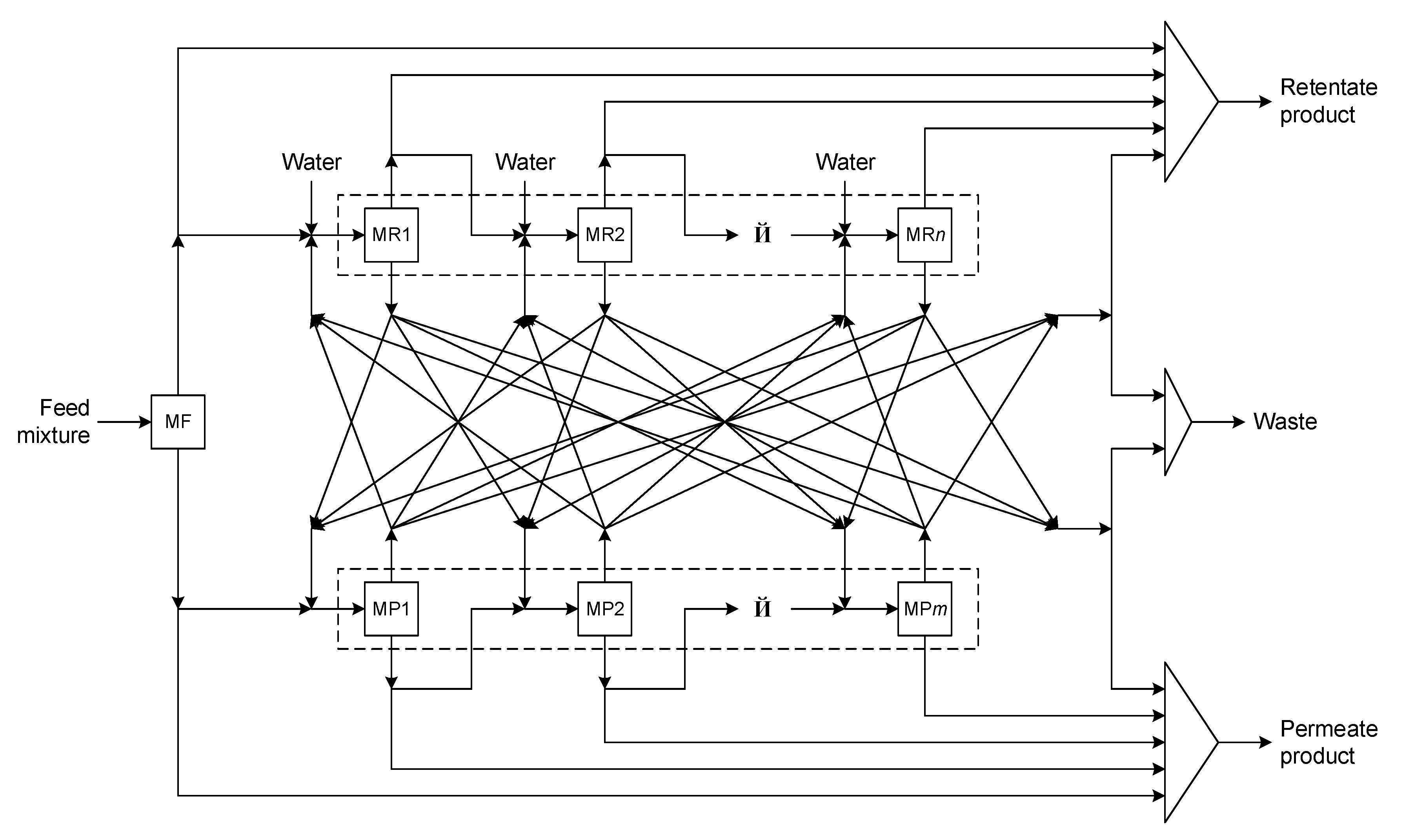
The modeling of a multistage NF system is based on the superstructure in Figure 2, where the membrane units are divided into three sections: the unit handling the feed mixture (j = MF), units handling retentates, or MR units ( j J MR = { MR 1 , MR 2 , } ), and units handling permeates, or MP units ( j J MP = { MP 1 , MP 2 , } ). Because the feed mixture is the only input to unit MF, the inlet flowrate and concentration of unit MF are the feed flowrate ( F F ) and concentration ( C i F ), as stated in Equations (5) and (6).
f j in | j = MF = F F
c i j in | j = MF = C i F       i I
Equations (7) and (8) describe the inlet flowrate and component balances for unit j J MR , respectively. The inlet stream of unit j J MR may consist of the retentate from the previous unit (j − 1), retentates from units j J MP , and freshwater, which is added to control the concentration and viscosity of the solution.
f j in = f j j | j = MF , j = MR 1 + f j 1 , j | j J MR { MR 1 } + j J MP f j j + f j FW       j J MR
f j in c i j in = f j j c i j R | j = MF , j = MR 1 + f j 1 , j c i , j 1 R | j J MR { MR 1 } + j J MP f j j c i j R + f j FW C i FW       i I , j J MR
where f j j is the flowrate from unit j′ to unit j; f j FW is the amount of freshwater added to unit j; C i FW is the concentration of component i in freshwater.
Equations (9) and (10) describe the inlet flowrate and component balances for unit j J MP , respectively. The inlet stream of unit j J MP may consist of the permeate from the previous unit and permeates from units j J MR .
f j in = f j j | j = MF , j = MP 1 + f j 1 , j | j J MP { MP 1 } + j J MR f j j       j J MP
f j in c i j in = f j j c i j P | j = MF , j = MP 1 + f j 1 , j c i , j 1 P | j J MP { MP 1 } + j J MR f j j c i j P       i I , j J MP
The outlet flowrate balances for unit MF are given by Equations (11) and (12). The retentate of unit MF may be sent to unit MR1 or collected as part of the retentate product. Similarly, the permeate of unit MF may be sent to unit MP1 or collected as part of the permeate product.
f j R | j = MF = f j j | j = MF , j = MR 1 + f j RP | j = MF
f j P | j = MF = f j j | j = MF , j = MP 1 + f j PP | j = MF
where f j RP is the flowrate from unit j to the retentate product, and f j PP is the flowrate from unit j to the permeate product.
Equations (13) and (14) describe the outlet flowrate balances for units j J MR . The retentates of these units may be sent to the next unit (j + 1) or collected as part of the retentate product, except the last unit (j = MRn), of which the retentate is part of the product. The permeates of units j J MR may be sent to units j J MP as inputs, collected as part of the permeate product, or purged as waste.
f j R = f j , j + 1 | j J MR { MR n } + f j RP j J MR
f j P = j J MP f j j + f j PP + f j W       j J MR
where f j W is the flowrate from unit j to waste.
Equations (15) and (16) describe the outlet flowrate balances for units j J MP . The retentates of these units may be sent to units j J MR as inputs, collected as part of the retentate product, or purged as waste. The permeates of units j J MP may be sent to the next unit or collected as part of the permeate product, except the last unit (j = MPm), of which the permeate is part of the product.
f j R = j J MR f j j + f j RP + f j W       j J MP
f j P = f j , j + 1 | j J MP { MP m } + f j PP j J MP
Equations (17) and (18) describe the flowrate and component balances for the retentate product, respectively. The flowrate and component balances for the permeate product are given by Equations (19) and (20), respectively.
f R , prod = j J f j RP
f R , prod c i R , prod = j J f j RP c i j R       i I
f P , prod = j J f j PP
f P , prod c i P , prod = j J f j PP c i j P       i I
where f R , prod is the retentate product flowrate; f P , prod is the permeate product flowrate; c i R , prod and c i P , prod are the respective concentrations of component i. These variables are constrained by the product specifications.
In addition, the flowrate and component balances for the waste are given by Equations (21) and (22), respectively.
f waste = j J f j W
f waste c i waste = j J MR f j W c i j P + j J MP f j W c i j R       i I
where f waste and c i waste are the waste flowrate and concentration (of component i), respectively.
Equation (23) imposes the lower ( F j L ) and upper limits ( F j U ) to the inlet flowrate when unit j is used ( y j = 1 ), and forces the inlet flowrate to zero when unit j is not used ( y j = 0 ).
F j L y j f j in F j U y j       j J
where y j is a binary variable denoting the existence of unit j.
Equations (24) and (25) state that unit j + 1 will not be used if unit j does not exist. These constraints ensure proper sequencing of the membrane units.
y j + 1 y j       j J MR { MR n }
y j + 1 y j       j J MP { MP m }
The objective function is to minimize the total capital cost of membrane units, as given in Equation (26).
min z = j J β ( f j in F * ) γ
where z represents the objective value; β is the base cost for a membrane unit with an inlet flowrate of F * ; γ is a constant.
Equations (1)–(26) constitute an MINLP model, for which global optimality may not always be guaranteed. The notation used in the formulation is given in Appendix A. In the next section, a case study is presented to illustrate the proposed approach. The MINLP model is implemented and solved in GAMS on a Core i7-9700K, 3.60 GHz processor, using BARON as the solver. Solutions were found with reasonable processing time.

4. Case Study

A bagasse hydrolysis solution is to be processed for fermentation in a bioethanol production process. As shown in Figure 3, bagasse is hydrolyzed first using the ITRI’s ZnCl2 solution. After the subsequent distillation and multistage filtration, the resulting hydrolysis solution containing 2 wt% glucose, 6 wt% ZnCl2 and 92 wt% water is further treated by NF to remove ZnCl2. Two cases are considered in this case study. Case 1 uses membrane performance data obtained from experiments [5], while case 2 assumes hypothetical parameters to analyze the impact of membrane performance on the optimal network configuration. In either case, the objective is to synthesize the minimum-cost NF membrane network that achieves the desired separation.

4.1. Case 1: Membrane Network Synthesis Using Experimental Data

Table 1 shows the data for membrane units. These performance data are obtained experimentally using commercially available NF membranes of Dow Chemicals [5]. It can be seen that the removal ratio of ZnCl2 varies according to the membrane type and the inlet concentration. Therefore, additional constraints in Equations (27)–(31) are needed to assign removal ratios to membrane units:
c i j in | i = ZnCl 2 1.5 + U ( 1 k K y j k l | l = I )       j J
1.5 U ( 1 k K y j k l | l = II ) + ε c i j in | i = ZnCl 2 4 + U ( 1 k K y j k l | l = II )     j J
c i j in | i = ZnCl 2 4 U ( 1 k K y j k l | l = III ) + ε       j J
k K l L y j k l = y j       j J
r i j | i = ZnCl 2 = k K l L y j k l ( 1 R R k l )       j J
where y j k l is a binary variable denoting if membrane unit j is of type k and its inlet ZnCl2 concentration lies in interval l; U is an arbitrary large number; ε is a small value; R R k l is the ZnCl2 removal ratio of membrane type k when the inlet ZnCl2 concentration lies in interval l. Equation (27) is active when the inlet ZnCl2 concentration lies in interval I, in which case one membrane type is selected for unit j ( k K y j k , I = 1 ). Similarly, Equations (28) and (29) are active when the inlet ZnCl2 concentration lies in intervals II and III, respectively. Equation (30) states that if unit j is used, then its inlet ZnCl2 concentration lies in one of the concentration intervals and a membrane type is selected. The retention of ZnCl2 in the retentate of unit j is calculated from the assigned ZnCl2 removal ratio in Equation (31). With two membrane types, the objective function in Equation (26) is rewritten as in Equation (32).
min z = j J k K l L β k y j k l ( f j in F * ) γ
where β k is the base cost for a membrane unit of type k with an inlet flowrate of F * .
Three scenarios are analyzed in this case. Scenario 1 considers the use of only NF1 membranes, scenario 2 only NF2 membranes, while scenario 3 both NF1 and NF2 membranes. Assuming a feed flowrate of 3 t/h (to unit MF), the inlet flowrate of MR units is fixed at the base flowrate of 3 t/h. For each scenario, the NF membrane network is designed to meet the specifications that the retentate product has a minimum glucose/ZnCl2 ratio of 10 and a minimum glucose recovery of 90%, as given in Equations (33) and (34). No specifications for the permeate product are set in this case.
c glucose R , prod c ZnCl 2 R , prod 10
f R , prod c glucose R , prod F F C glucose F 90 %
Solving the MINLP model (Equation (32) subject to Equations (1)–(25), (27)–(31), (33) and (34)) for scenarios 1–3 yields the results in Table 2. It can be seen that the specified glucose/ZnCl2 ratio of 10 in the retentate product is achieved in all scenarios, while the specified glucose recovery of 90% in the retentate product can be achieved only in scenarios 2 and 3. With a maximum number of 20 for MR units, the maximum achievable glucose recovery (in the retentate product) in scenario 1 is 78.4%, which is determined by maximizing the glucose recovery in Equation (33). The reason that the glucose recovery specification is not met in scenario 1 is that the ZnCl2 removal ratio of NF1 is only 10% when the inlet ZnCl2 concentration ≤ 1.5 wt%. Therefore, the glucose recovery specification cannot be met in scenario 1 unless the number of MR units is up to 30. Figure 4 shows the inlet concentrations and the corresponding retention of glucose and ZnCl2 in MF and MR units. Obviously, most of the inlet ZnCl2 concentrations of MR units lie in concentration interval I (≤1.5 wt%), in which the ZnCl2 removal ratio of NF2 is twice that of NF1 (see Table 1). This explains why a better solution is found in scenario 2, where both specifications for the retentate product are achieved with fewer membrane units and a lower capital cost. When both membrane types are used, NF2 can be used for membrane units with inlet ZnCl2 concentrations in interval I and NF1 in intervals II and III to give higher ZnCl2 removal ratios, as shown in Table 3. However, to minimize the capital cost, NF1 may be selected instead of NF2 for units with an inlet ZnCl2 concentration in interval I (MR9 in Table 3), if the product specifications can still be met. Accordingly, scenario 3 has the best solution, with significant cost reductions of 36.9% and 34.8% compared to scenarios 1 and 2, respectively.
Figure 5 shows the retentate concentrations and glucose/ZnCl2 ratios in MF and MR units. Other details of the NF membrane networks for scenarios 1–3 are given in Tables S1–S3 in the Supplementary Materials, including the flowrates of streams between membrane units and streams to products.
In addition, without specifications for the permeate product, quite some ZnCl2 is found in the waste stream (see Table 2). In fact, ZnCl2 is more expensive than glucose. Therefore, specifications for the permeate product will be set in case 2 for ZnCl2 recovery and waste reduction.

4.2. Case 2: Membrane Network Synthesis Using Hypothetical Parameters

Although the use of both NF1 and NF2 membranes in case 1 resulted in a significant reduction in capital cost, there were still a large number of membrane units (=12) in the network, due to low ZnCl2 removal ratios (<50%) in most of the membrane units. In this case, an alternative membrane type with hypothetical performance is used. The parameters are shown in Table 4. Compared to NF1 and NF2, the hypothetical membrane (NF3) has lower glucose retention, a constant ZnCl2 removal ratio of 70% ( r ZnCl 2 , j = 30 % ) and a higher capital cost for the same unit size.
As in case 1, the flowrate of the feed mixture to unit MF is assumed to be 3 t/h, and the inlet flowrate of MR units is fixed at the base flowrate of 3 t/h. The NF membrane network is designed to meet the specifications for both retentate and permeate products. In addition to a minimum glucose/ZnCl2 ratio of 10 and a minimum glucose recovery of 90% in the retentate product, in this case the permeate product is required to have a minimum ZnCl2/glucose ratio of 10 and a minimum ZnCl2 recovery of 90%, as given in Equations (35) and (36).
c ZnCl 2 P , prod c glucose P , prod 10
f P , prod c ZnCl 2 P , prod F F C ZnCl 2 F 90 %
Solving the MINLP model of Equation (26) subject to Equations (1)–(25) and (33)–(36) yields the results in Table 5. It can be seen that with the specifications for the permeate product, there is no longer a waste stream. Also, with a much higher ZnCl2 removal ratio, the product specifications are met with only six membrane units, hence a considerable cost reduction of 30.2% compared to the solution for scenario 3 of case 1. While the retentate product just meets the glucose/ZnCl2 ratio and glucose recovery specifications, the permeate product overshoots and achieves a ZnCl2/glucose ratio of 29.1 and a ZnCl2 recovery of 97%. This is because not much glucose remains in the permeate product when the specifications for the retentate product are met. Figure 6 shows the corresponding NF membrane network, with some flowrates between membrane units given in Table 6.

4.3. Comparison and Discussion

It is worth mentioning that Kuo et al. [5] presented a multistage NF process for the removal of ZnCl2 from a bagasse hydrolysis solution. Through three NF membrane units in series, the concentration of ZnCl2 decreases by 74.8% and the glucose/ZnCl2 ratio increases from 0.245 to 1.268. There is no recovery of ZnCl2 in their design. In this work, NF networks were synthesized to increase the glucose/ZnCl2 ratio from 0.333 in the feed mixture to 10 in the retentate product stream. The proposed superstructure optimization approach allows the optimal system configuration to be determined systematically according to product specifications, resulting in a sophisticated system achieving improved performance. Moreover, the waste stream can be eliminated by recovering ZnCl2 in the permeate product stream.

5. Conclusions

A superstructure-based approach has been developed in this paper for the separation of hydrolysis solutions in bioethanol production using NF membranes. The optimization model for NF membrane network synthesis consists mainly of mass balances for individual membrane units and their interconnections, with the objective of minimizing the total capital cost of membrane units. A case study of a bagasse hydrolysis solution for glucose/ZnCl2 separation was solved to illustrate the proposed approach. First, experimental data for the performance of two types of NF membranes were used. The results show that using both membrane types gives higher ZnCl2 removal ratios and thus a better solution with significant reductions in the number of membrane units and capital cost. Hypothetical parameters were then used to analyze the effect of membrane performance on the optimal network configuration. It was found that despite the lower glucose retention, the higher ZnCl2 removal ratio allows the product specifications to be achieved with much fewer membrane units at a considerably reduced total capital cost. This indicates that the economic performance of the NF membrane separation system can be improved by increasing the ZnCl2 removal ratio. Such analysis is thus useful for debottlenecking the system. The present study focuses on structural optimization using a shortcut model for membrane units. Future work will involve detailed membrane models to optimize the operating conditions (e.g., pressure). A more sophisticated objective function will also be used to refine the membrane network. In addition, although developed for NF membrane network synthesis, the proposed mathematical model is generic in nature and can be extended to other separation problems.

Supplementary Materials

The following are available online at https://www.mdpi.com/2227-9717/9/1/168/s1, Table S1: flowrates in the NF membrane network for scenario 1 (t/h), Table S2: flowrates in the NF membrane network for scenario 2 (t/h), Table S3: flowrates in the NF membrane network for scenario 3 (t/h).

Author Contributions

Conceptualization, C.-Y.S. and J.-Y.L.; methodology, C.-Y.S., W.-C.H. and J.-Y.L.; software, B.-Y.J.; validation, B.-Y.J. and J.-Y.L.; formal analysis, B.-Y.J. and J.-Y.L.; investigation, C.-Y.S., W.-C.H. and J.-Y.L.; resources, J.-Y.L.; data curation, P.-J.Y. and M.-H.W.; writing—original draft preparation, C.-Y.S., B.-Y.J. and J.-Y.L.; writing—review and editing, C.-Y.S. and J.-Y.L.; visualization, B.-Y.J. and J.-Y.L.; supervision, Y.-H.C. and J.-Y.L.; project administration, J.-Y.L.; funding acquisition, J.-Y.L. All authors have read and agreed to the published version of the manuscript.

Funding

This research was funded by the Ministry of Science and Technology (MOST), R.O.C. (grant number 109-2221-E-027-038) and the Bureau of Energy, the Ministry of Economic Affairs, R.O.C. (grant number 109-D0109). The APC was funded by the MOST.

Institutional Review Board Statement

Not applicable.

Informed Consent Statement

Not applicable.

Data Availability Statement

Data will be made available on request.

Acknowledgments

The authors thank the “Research Center of Energy Conservation for New Generation of Residential, Commercial, and Industrial Sectors” for financial support from the Featured Areas Research Center Program within the framework of the Higher Education Sprout Project by the Ministry of Education (MOE), Taiwan.

Conflicts of Interest

The authors declare no conflict of interest. The funders had no role in the design of the study; in the collection, analyses, or interpretation of data; in the writing of the manuscript, or in the decision to publish the results.

Appendix A. Nomenclature

Notation used in the MINLP model is given below.

Appendix A.1. Indices and Sets

i I components
j J membrane units
j J MP membrane units handling permeates
k K membrane units handling retentates
k K membrane types
l L inlet ZnCl2 concentration intervals

Appendix A.2. Parameters

C i F concentration of component i in the feed mixture
C i FW concentration of component i in freshwater
F F flowrate of the feed mixture
F * base flowrate of membrane units
F j L lower limit to the inlet flowrate of membrane unit j
F j U upper limit to the inlet flowrate of membrane unit j
R R k l ZnCl2 removal ratio of membrane type k with the inlet ZnCl2 concentration in interval l
U arbitrary large number
β base cost for a membrane unit with an inlet flowrate of F *
β k base cost for a membrane unit of type k with an inlet flowrate of F *
γ constant cost exponent
ε arbitrary small value
θ j cut fraction of membrane unit j

Appendix A.3. Variables

c i P , prod concentration of component i in the permeate product
c i R , prod concentration of component i in the retentate product
c i waste concentration of component i in the waste stream
c i j in concentration of component i in the inlet stream of membrane unit j
c i j P concentration of component i in the permeate of membrane unit j
c i j R concentration of component i in the retentate of membrane unit j
f P , prod flowrate of the permeate product
f R , prod flowrate of the retentate product
f waste flowrate of the waste stream
f j FW flowrate of freshwater to membrane unit j
f j in flowrate of the inlet stream of membrane unit j
f j P flowrate of the permeate of membrane unit j
f j PP flowrate from membrane unit j to the permeate product
f j R flowrate of the retentate of membrane unit j
f j RP flowrate from membrane unit j to the retentate product
f j W flowrate from membrane unit j to waste
f j j flowrate from membrane unit j to unit j
r i j retention of component i in membrane unit j
y j binary indicating if membrane unit j is used
z objective value

References

  1. Ragauskas, A.J.; Williams, C.K.; Davison, B.H.; Britovsek, G.; Cairney, J.; Eckert, C.A.; Frederick, W.J., Jr.; Hallett, J.P.; Leak, D.J.; Liotta, C.L.; et al. The path forward for biofuels and biomaterials. Science 2006, 311, 484–489. [Google Scholar] [CrossRef] [Green Version]
  2. Fernando, S.; Adhikari, S.; Chandrapal, C.; Murali, N. Biorefineries: Current status, challenges, and future direction. Energy Fuels 2006, 20, 1727–1737. [Google Scholar] [CrossRef]
  3. Chen, L.F.; Yang, C.-M. Selective Hydrolysis of Cellulose to Glucose without Degradation of Glucose Using Zinc Chloride. U.S. Patent 4,525,218 A, 25 June 1985. [Google Scholar]
  4. Hung, W.-C.; Shih, R.-F.; Chen, J.-Y.; Lin, H.-T.; Lee, H.-T.; Wan, H.-P. Method for Preparing Sugars. U.S. Patent 9,150,937 B2, 6 October 2015. [Google Scholar]
  5. Kuo, Y.-T.; Chen, J.-S.; Yang, T.-Y.; Wan, H.-P. Technical and economic approach of bioethanol production from nanofiltration of biomass chemical hydrolysis solutions. Appl. Energy 2018, 215, 426–436. [Google Scholar] [CrossRef]
  6. Bargeman, G.; Vollenbroek, J.M.; Straatsma, J.; Schroën, C.G.P.H.; Boom, R.M. Nanofiltration of multi-component feeds. Interactions between neutral and charged components and their effect on retention. J. Membr. Sci. 2005, 247, 11–20. [Google Scholar] [CrossRef]
  7. Cuartas-Uribe, B.; Vincent-Vela, M.C.; Álvarez-Blanco, S.; Alcaina-Miranda, M.I.; Soriano-Costa, E. Nanofiltration of sweet whey and prediction of lactose retention as a function of permeate flux using the Kedem–Spiegler and Donnan Steric partioning models. Sep. Purif. Technol. 2007, 56, 38–46. [Google Scholar] [CrossRef]
  8. Nilsson, M.; Trägårdh, G.; Östergren, K. The influence of pH, salt and temperature on nanofiltration performance. J. Membr. Sci. 2008, 312, 97–106. [Google Scholar] [CrossRef]
  9. Bouranene, S.; Szymczyk, A.; Fievet, P.; Vidonne, A. Effect of salts on the retention of polyethyleneglycol by a nanofiltration ceramic membrane. Desalination 2009, 240, 94–98. [Google Scholar] [CrossRef]
  10. Dalwani, M.; Benes, N.E.; Bargeman, G.; Stamatialis, D.; Wessling, M. Effect of pH on the performance of polyamide/polyacrylonitrile based thin film composite membranes. J. Membr. Sci. 2011, 372, 228–238. [Google Scholar] [CrossRef]
  11. Mencarelli, L.; Chen, Q.; Pagot, A.; Grossmann, I.E. A review on superstructure optimization approaches in process system engineering. Comput. Chem. Eng. 2020, 136, 106808. [Google Scholar] [CrossRef]
  12. El-Halwagi, M.M. Synthesis of reverse-osmosis networks for waste reduction. AIChE J. 1992, 38, 1185–1198. [Google Scholar] [CrossRef]
  13. Voros, N.; Maroulis, Z.B.; Marinos-Kouris, D. Optimization of reverse osmosis networks for seawater desalination. Comput. Chem. Eng. 1996, 20, S345–S350. [Google Scholar] [CrossRef]
  14. Voros, N.G.; Maroulis, Z.B.; Marinos-Kouris, D. Short-cut structural design of reverse osmosis desalination plants. J. Membr. Sci. 1997, 127, 47–68. [Google Scholar] [CrossRef]
  15. Lu, Y.-Y.; Hu, Y.-D.; Zhang, X.-L.; Wu, L.-Y.; Liu, Q.-Z. Optimum design of reverse osmosis system under different feed concentration and product specification. J. Membr. Sci. 2007, 287, 219–229. [Google Scholar] [CrossRef]
  16. Lu, Y.; Liao, A.; Hu, Y. Design of reverse osmosis networks for multiple freshwater production. Korean J. Chem. Eng. 2013, 30, 988–996. [Google Scholar] [CrossRef]
  17. Du, Y.; Xie, L.; Wang, Y.; Xu, Y.; Wang, S. Optimization of reverse osmosis networks with spiral-wound modules. Ind. Eng. Chem. Res. 2012, 51, 11764–11777. [Google Scholar] [CrossRef]
  18. Sassi, K.M.; Mujtaba, I.M. MINLP based superstructure optimization for boron removal during desalination by reverse osmosis. J. Membr. Sci. 2013, 440, 29–39. [Google Scholar] [CrossRef]
  19. Saif, Y.; Almansoori, A. Synthesis of reverse osmosis desalination network under boron specifications. Desalination 2015, 371, 26–36. [Google Scholar] [CrossRef]
  20. Alnouri, S.Y.; Linke, P. A systematic approach to optimal membrane network synthesis for seawater desalination. J. Membr. Sci. 2012, 417-418, 96–112. [Google Scholar] [CrossRef]
  21. Abejón, R.; Garea, A.; Irabien, A. Optimum design of reverse osmosis systems for hydrogen peroxide ultrapurification. AIChE J. 2012, 58, 3718–3730. [Google Scholar] [CrossRef]
  22. Chauhan, V.M.; Alnouri, S.Y.; Linke, P.; Abdel-Wahab, A. Synthesis of integrated membrane desalination and salt production networks. Desalination 2016, 400, 25–37. [Google Scholar] [CrossRef]
  23. Parra, A.; Noriega, M.; Yokohama, L.; Bagajewicz, M. Reverse osmosis network rigorous design optimization. Ind. Eng. Chem. Res. 2019, 58, 3060–3071. [Google Scholar] [CrossRef]
  24. Qi, R.; Henson, M.A. Optimal design of spiral-wound membrane networks for gas separations. J. Membr. Sci. 1998, 148, 71–89. [Google Scholar] [CrossRef] [Green Version]
  25. Kookos, I.K. A targeting approach to the synthesis of membrane networks for gas separations. J. Membr. Sci. 2002, 208, 193–202. [Google Scholar] [CrossRef]
  26. Uppaluri, R.V.S.; Linke, P.; Kokossis, A.C. Synthesis and optimization of gas permeation membrane networks. Ind. Eng. Chem. Res. 2004, 43, 4305–4322. [Google Scholar] [CrossRef]
  27. Uppaluri, R.V.S.; Smith, R.; Linke, P.; Kokossis, A.C. On the simultaneous optimization of pressure and layout for gas permeation membrane systems. J. Membr. Sci. 2006, 280, 832–848. [Google Scholar] [CrossRef]
  28. Arias, A.M.; Mussati, M.C.; Mores, P.L.; Scenna, N.J.; Caballero, J.A.; Mussati, S.F. Optimization of multi-stage membrane systems for CO2 capture from flue gas. Int. J. Greenh. Gas Control 2016, 53, 371–390. [Google Scholar] [CrossRef]
  29. Shafiee, A.; Nomvar, M.; Liu, Z.; Abbas, A. Automated process synthesis for optimal flowsheet design of a hybrid membrane cryogenic carbon capture process. J. Clean. Prod. 2017, 150, 309–323. [Google Scholar] [CrossRef]
  30. Ramírez-Santos, Á.A.; Bozorg, M.; Addis, B.; Piccialli, V.; Castel, C.; Favre, E. Optimization of multistage membrane gas separation processes. Example of application to CO2 capture from blast furnace gas. J. Membr. Sci. 2018, 566, 346–366. [Google Scholar] [CrossRef]
  31. Lee, S.; Binns, M.; Kim, J.-K. Automated process design and optimization of membrane-based CO2 capture for a coal-based power plant. J. Membr. Sci. 2018, 563, 820–834. [Google Scholar] [CrossRef]
  32. González-Bravo, R.; Nápoles-Rivera, F.; Ponce-Ortega, J.M.; Nyapathi, M.; Elsayed, N.; El-Halwagi, M.M. Synthesis of optimal thermal membrane distillation networks. AIChE J. 2015, 61, 448–463. [Google Scholar] [CrossRef]
  33. Wu, W.; Yenkie, K.; Maravelias, C.T. A superstructure-based framework for bio-separation network synthesis. Comput. Chem. Eng. 2017, 96, 1–17. [Google Scholar] [CrossRef] [Green Version]
  34. Baaqeel, H.; El-Halwagi, M.M. Optimal multiscale capacity planning in seawater desalination systems. Processes 2018, 6, 68. [Google Scholar] [CrossRef] [Green Version]
  35. Oke, D.; Majozi, T.; Mukherjee, R.; Sengupta, D.; El-Halwagi, M.M. Simultaneous energy and water optimisation in shale exploration. Processes 2018, 6, 86. [Google Scholar] [CrossRef] [Green Version]
  36. Mores, P.L.; Arias, A.M.; Scenna, N.J.; Mussati, M.C.; Mussati, S.F. Cost-based comparison of multi-stage membrane configurations for carbon capture from flue gas of power plants. Int. J. Greenh. Gas Control 2019, 86, 177–190. [Google Scholar] [CrossRef]
  37. Tao, J.; Wang, J.; Zhu, L.; Chen, X. Integrated design of multi-stage membrane separation for landfill gas with uncertain feed. J. Membr. Sci. 2019, 590, 117260. [Google Scholar] [CrossRef]
  38. Martín-Hernández, E.; Guerras, L.S.; Martín, M. Optimal technology selection for the biogas upgrading to biomethane. J. Clean. Prod. 2020, 267, 122032. [Google Scholar] [CrossRef]
Figure 1. NF membrane unit.
Processes 09 00168 g001
Figure 2. Superstructure for an NF membrane network.
Processes 09 00168 g002
Figure 3. Bagasse hydrolysis and subsequent separation processes.
Processes 09 00168 g003
Figure 4. Variations of inlet concentration and retention in MF and MR units: (a) inlet concentration for scenario 1; (b) retention for scenario 1; (c) inlet concentration for scenario 2; (d) retention for scenario 2; (e) inlet concentration for scenario 3; (f) retention for scenario 3.
Processes 09 00168 g004
Figure 5. Variations of retentate concentration and the glucose/ZnCl2 ratio in MF and MR units: (a) retentate concentration for scenario 1; (b) glucose/ZnCl2 ratio for scenario 1; (c) retentate concentration for scenario 2; (d) glucose/ZnCl2 ratio for scenario 2; (e) retentate concentration for scenario 3; (f) glucose/ZnCl2 ratio for scenario 3.
Processes 09 00168 g005
Figure 6. Optimal NF membrane network for case 2.
Processes 09 00168 g006
Table 1. Membrane performance and cost data for case 1.
TypeCut FractionGlucose Retention (%)ZnCl2 Removal Ratio (%)Capital Cost (NTD)
NF11/398.2710 1/45 2/75 3 8000 ( f j in / 3 ) 0.7
NF21/398.520 1/30 2/65 3 9600 ( f j in / 3 ) 0.7
1 Inlet ZnCl2 concentration ≤ 1.5 wt% (concentration interval I); 2 1.5 wt% < inlet ZnCl2 concentration ≤ 4 wt% (concentration interval II); 3 4 wt% < inlet ZnCl2 concentration (concentration interval III).
Table 2. Main results for case 1.
ParameterScenario 1Scenario 2Scenario 3
Retentate product flowrate (t/h)1.2371.0871.401
Retentate product concentration (wt%)Glucose = 3.805Glucose = 4.967Glucose = 3.854
ZnCl2 = 0.381ZnCl2 = 0.497ZnCl2 = 0.385
Permeate product flowrate (t/h)16.53519.3688.796
Permeate product concentration (wt%)Glucose = 0.026Glucose = 0.019Glucose = 0.021
ZnCl2 = 0.864ZnCl2 = 0.698ZnCl2 = 1.602
Waste flowrate (t/h)19.4655.23110.727
Waste concentration (wt%)Glucose = 0.045Glucose = 0.044Glucose = 0.038
ZnCl2 = 0.167ZnCl2 = 0.755ZnCl2 = 0.315
Number of membrane units211612
(MF/MR1-MR19/MP1)(MF/MR1-MR14/MP1)(MF/MR1-MR10/MP1)
Inlet flowrate to MP11216.2037.433
Total capital cost (NTD)181,112175,261114,298
Glucose recovery in the retentate product (%)78.49090
Glucose/ZnCl2 ratio in the retentate product101010
Table 3. Selection of membrane types for scenario 3.
UnitMembrane TypeInlet Flowrate (t/h)
MFNF13
MR1NF13
MR2NF13
MR3NF23
MR4NF23
MR5NF23
MR6NF23
MR7NF23
MR8NF23
MR9NF13
MR10NF23
MP1NF17.433
Table 4. Membrane performance and cost data for case 2.
TypeCut FractionGlucose Retention (%)ZnCl2 Removal Ratio (%)Capital Cost (NTD)
NF31/3857012,000 ( f j in / 3 ) 0.7
Table 5. Main results for case 2.
ParameterValue
Retentate product flowrate (t/h)1
Retentate product concentration (wt%)Glucose = 5.4
ZnCl2 = 0.54
Permeate product flowrate (t/h)4.947
Permeate product concentration (wt%)Glucose = 0.121
ZnCl2 = 3.529
Waste flowrate (t/h)0
Number of membrane units6
(MF/MR1-MR3/MP1-MP2)
Inlet flowrate to MP units (t/h)MP1 = 6.312
MP2 = 2.847
Total capital cost (NTD)79,766
Glucose recovery in the retentate product (%)90%
Glucose/ZnCl2 ratio in the retentate product10
ZnCl2 recovery in the permeate product (%)97%
ZnCl2/glucose ratio in the permeate product29.1
Table 6. Flowrates between membrane units for case 2 (t/h).
From MR Units to MP UnitsFrom MP Units to MR Units
MR1 to MP1 = 2MP1 to MR1 = 2
MR2 to MP1 = 2MP1 to MR2 = 0.104
MR3 to MP1 = 0.653MP2 to MR2 = 0.949
MR3 to MP2 = 1.347
Publisher’s Note: MDPI stays neutral with regard to jurisdictional claims in published maps and institutional affiliations.

