Novel Dual Beam Cascaded Schemes for 346 GHz Harmonic-Enhanced TWTs
by
Ruifeng Zhang
1, 
Qi Wang
1,
Difu Deng
1,
Yao Dong
1,
Fei Xiao
1,
Gil Travish
2 and
Huarong Gong
1,* 1
School of Electronic Science and Engineering, University of Electronic Science and Technology of China, Chengdu 610054, China
2
ViBo Health LLC, Westwood Plaza, Los Angeles, CA 90095, USA
*
Author to whom correspondence should be addressed.
Electronics 2021, 10(2), 195; https://doi.org/10.3390/electronics10020195
Submission received: 25 December 2020
/
Revised: 13 January 2021
/
Accepted: 14 January 2021
/
Published: 16 January 2021
(This article belongs to the Special Issue Design, Technologies and Applications of High Power Vacuum Electronic Devices from Microwave to THz Band)
Abstract
:The applications of terahertz (THz) devices in communication, imaging, and plasma diagnostic are limited by the lack of high-power, miniature, and low-cost THz sources. To develop high-power THz source, the high-harmonic traveling wave tube (HHTWT) is introduced, which is based on the theory that electron beam modulated by electromagnetic (EM) waves can generate high harmonic signals. The principal analysis and simulation results prove that amplifying high harmonic signal is a promising method to realize high-power THz source. For further improvement of power and bandwidth, two novel dual-beam schemes for high-power 346 GHz TWTs are proposed. The first TWT is comprised of two cascaded slow wave structures (SWSs), among which one SWS can generate a THz signal by importing a millimeter-wave signal and the other one can amplify THz signal of interest. The simulation results show that the output power exceeds 400 mW from 340 GHz to 348 GHz when the input power is 200 mW from 85 GHz to 87 GHz. The peak power of 1100 mW is predicted at 346 GHz. The second TWT is implemented by connecting a pre-amplification section to the input port of the HHTWT. The power of 600 mW is achieved from 338 GHz to 350 GHz. The 3-dB bandwidth is 16.5 GHz. In brief, two novel schemes have advantages in peak power and bandwidth, respectively. These two dual-beam integrated schemes, constituted respectively by two TWTs, also feature rugged structure, reliable performance, and low costs, and can be considered as promising high-power THz sources.
1. Introduction
Terahertz (THz) devices are widely used in high data-rate communication systems, plasma diagnostic, hazardous material detection, medical imaging, etc. However, the development of THz technology faces some challenges, such as lack of THz sources with high power, miniaturization, and low cost. Semiconductor THz sources and vacuum electronic THz sources are two common ones. Although semiconductor THz sources can produce high-power output up to milliwatt, they are usually troubled by over-high upfront cost. As a compromise, vacuum electronic devices (VEDs) may deliver higher output power with lower cost [1,2,3,4,5,6,7]. In 2004, a kind of compact THz free electron laser device was introduced by Stuart R A, with 1 kW pulsed power from 0.3 THz to 3 THz [8]. In 2010, Khanh Nguyen developed a high-gain multi-beam traveling wave tube (TWT) whose operating frequency range varies from 200 GHz to 250 GHz [9]. In 2011, Istok proposed a series of Backward-wave oscillators (BWOs) in which the grating line is utilized as slow wave structure (SWS). These devices can deliver several milliwatts output power at 1.4 THz [10]. In 2012, Paoloni et al. presented a cascade backward-wave amplifier operating at 1 THz [11]. From 2012 to 2016, Tucek et al. discussed a series of vacuum electronic amplifiers including one 100 mW 670 GHz prototype device driven by a novel solid-state source [12], a compact, microfabricated vacuum electronic amplifier with 39.4 mW of maximum output power from 0.835 THz to 0.875 THz [13], and a 29 mW 1.03 THz vacuum electronic with 20 dB of saturated gain and 5 GHz of instantaneous bandwidth [14]. In 2018, a folded waveguide (FWG) TWT is fabricated by Armstrong et al., with over 300 mW power in 231.5–235 GHz [15]. In 2020, Pan Pan et al. proposed a G-band continuous wave TWT. Saturated power of 20 W is generated from 217 GHz to 219.4 GHz [16].
For the development of nuclear fusion energy, the understanding of a critical plasma phenomenon as transport of the plasma is necessary. The collective Thompson scattering at THz frequency has been proven to be an adequate technology to map anomalous density fluctuation of electrons in the plasma, without perturbing its plasma behavior. The optically pumped far-infrared (FIR) laser is a practical radiation source for this technology and applied in the National Spherical Torus Experiment (NSTX) [17]. However, the features of the high price, large volume, and relatively low power restrict its mapping region. To extend the dimension of the plasma diagnostic, the BWOs operating at 346 GHz can be promising devices due to low cost, large output power, easy assembly, and compact volume. C. Paoloni et al. designed a 0.4 W double corrugated waveguide (DCW) BWO and a 1 W double-staggered grating (DSG) BWO [18]. J. Feng et al. designed a Grooved Single Grating (GSG) structure for 346 GHz BWO. The GSG circuit was fabricated by UV-lithographie galvanoformung abformung (LIGA) microelectromechanical technologies [19].
It should be noted that the BWO is strict about power source because BWO requires very suitable power source to maintain frequency stable. Phase noise of THz signal generation, which caused by power supply voltage ripple, should be reduced to ensure low bit-error rate in THz communication [20]. To reduce requirement of high-performance power source and obtain pure frequency spectrum of output power, we developed a kind of THz source, named high-harmonic TWT (HHTWT) [6,21]. Based on HHTWT, one new HHTWT and two novel types of THz sources operating at 346 GHz are proposed in this paper to improve the output power. The HHTWT can generate the THz band electromagnetic (EM) wave by amplifying the E-band signal. Compared with conventional THz signal sources, the application of high-power E-band signal source in HHTWT can input considerable signal into SWS. It can avoid input signal being interfered with and even drown out noise, which is caused by electron gun and discordance of SWS fabrication.
One of the novel THz sources, named cascaded enhanced HHTWT (CE-HHTWT), outputs the THz power by amplifying the signal, which is generated by HHTWT. The other one, named Pre-amplified HHTWT (PA-HHTWT), amplifies the THz band EM wave by inputting a relatively high power of fundamental wave into HHTWT.
This paper is organized as follows: HHTWT and two novel types of THz sources are introduced in Section 2, Section 3, and Section 4. Each section contains the operating principle, SWS design methodology, and simulation results. The analysis and design works are accomplished by CST particle studio. Section 5 is a summary of this paper.
2. HHTWT
2.1. Operating Principle of HHTWT
A HHTWT operating at 346 GHz is introduced firstly, which utilizes FWG as SWS. FWG is a promising type of SWS with wide bandwidth and high power. Compared with other conventional SWSs such as helix, FWG is of easy fabrication and assembling. Within it, the wave transmission path can be folded back upon itself multiple times, with a beam tunnel passing through its center. Energy exchange is achieved by synchronizing both the longitudinal energy flow speed and the electron beam velocity.
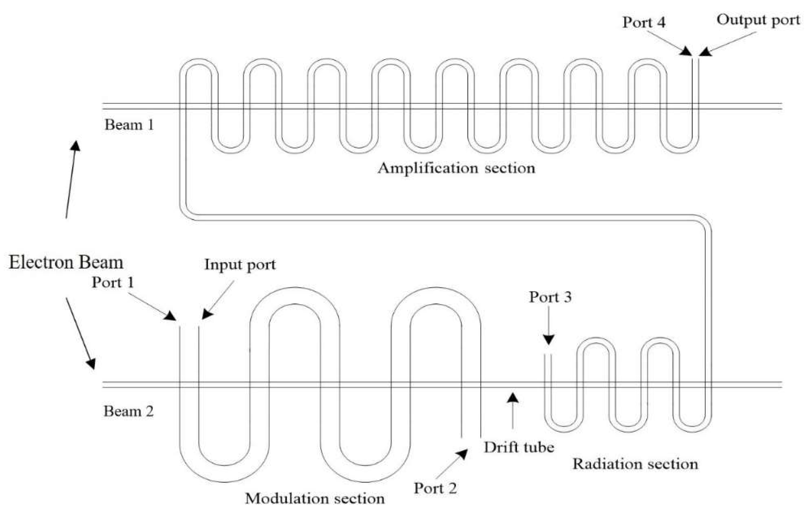
The schematic of the HHTWT SWS is shown in Figure 1. Port 1 and 4 are input and output ports, respectively. Attenuators are applied to match two severed ports (Port 2 and 3). The electron beam is sent from the electron gun into the tunnel. The SWS consists of three sections: Modulation section, drift tube, and radiation section. The modulation section operates at E band. The radiation section operates at THz band, corresponding to the fourth harmonic of input signal. There is also a drift tube between the modulation section and radiation section, where the EM wave is cutoff and only electron beam can pass.
In the modulation section, the velocity of electron beam is modulated by the E-band input signal. When the electron beam traverses the drift tube, the velocity modulation is transformed into longitudinal density modulation. If the cutoff frequency of the radiation section is 300 GHz, the fundamental wave and lower-order harmonic waves can be cut off in the radiation section, and then only high-frequency EM waves are excited and amplified by the high-order harmonic beam current. Hence, when inputting a signal at 86.5 GHz, we can get a 346 GHz output signal.
Compared with conventional FWG TWT, HHTWT is featured by adopting two high frequency structures operating in two different bands. The power of conventional THz band FWG TWT is restricted due to the high loss. It leads to low gain and overlong SWS. Generally, the low input power of THz source could exacerbate the deleterious effects. The introduction of modulation section could modulate the electron beam efficiently. It is also instructive to mitigate the demand for a THz high-power signal source, by using a millimeter-wave high-power source.
2.2. SWS Design Methodology of HHTWT
2.2.1. SWS Design
Two sections of the HHTWT, i.e., the modulation section and the radiation section, have different operating bands. The modulation section works at E band, and the radiation section operates at THz band. The dispersion curve and interaction impedance are obtained by 3D EM simulation. For the modulation section, the phase shift at the center frequency is set to , which ensures enough bandwidth. Then, interaction impedance should be set as high as possible. For the radiation section, the operating voltage should be the same with that in modulation section. The dispersion curve should also be flat to broaden bandwidth. Hence, the phase shift at the center frequency is set to . Figure 2 shows the dispersion curve, associated electron beam line, and interaction impedance of the modulation and the radiation sections, respectively. The structural parameters of the HHTWT are shown in Table 1, in which a, b, h, p, and r are the width of the broad edge of the waveguide, the length of the narrow side of the waveguide, the height of the straight rectangular waveguide, the axial period length, and the radius of the electron beam channel, respectively. Between the modulation section and the radiation section, the drift tube is adopted to decrease the risk of self-oscillation and realize the transition from velocity modulation to density modulation. The length determination of two sections and drift tube are discussed later.
2.2.2. The SWS Length Determination
The following simulation results are obtained by CST Particle Studio. The operating voltage and current are set to 18.4 kV and 10 mA in Particle in Cell (PIC) simulation, respectively. With frequency increased, transmission loss caused by skin effect becomes significantly high. The surface roughness, determined by different manufacture technology, also has significant effect on the transmission loss [21,22]. The precision computer numerical control (CNC) lathe and electric discharge machining (EDM) are main and mature processing methods and widely applied in the fabrication of THz band and E-band SWS [22,23]. By referencing experimental cases in [22,23] and summarizing our engineering experience in [21], the effective conductivities of sections operating at E band and THz band are set as 3.5 × 10⁷ S/m and 1 × 10⁷ S/m, respectively.
Due to low input power, the length of the modulation section should be long enough to ensure deep electron beam modulation. Hence, we construct 100 periods of modulation SWS, and determine the length of modulation section depending on the bunch state of electron beam. The frequency of input signal is 86.5 GHz, and the input power is 200 mW.
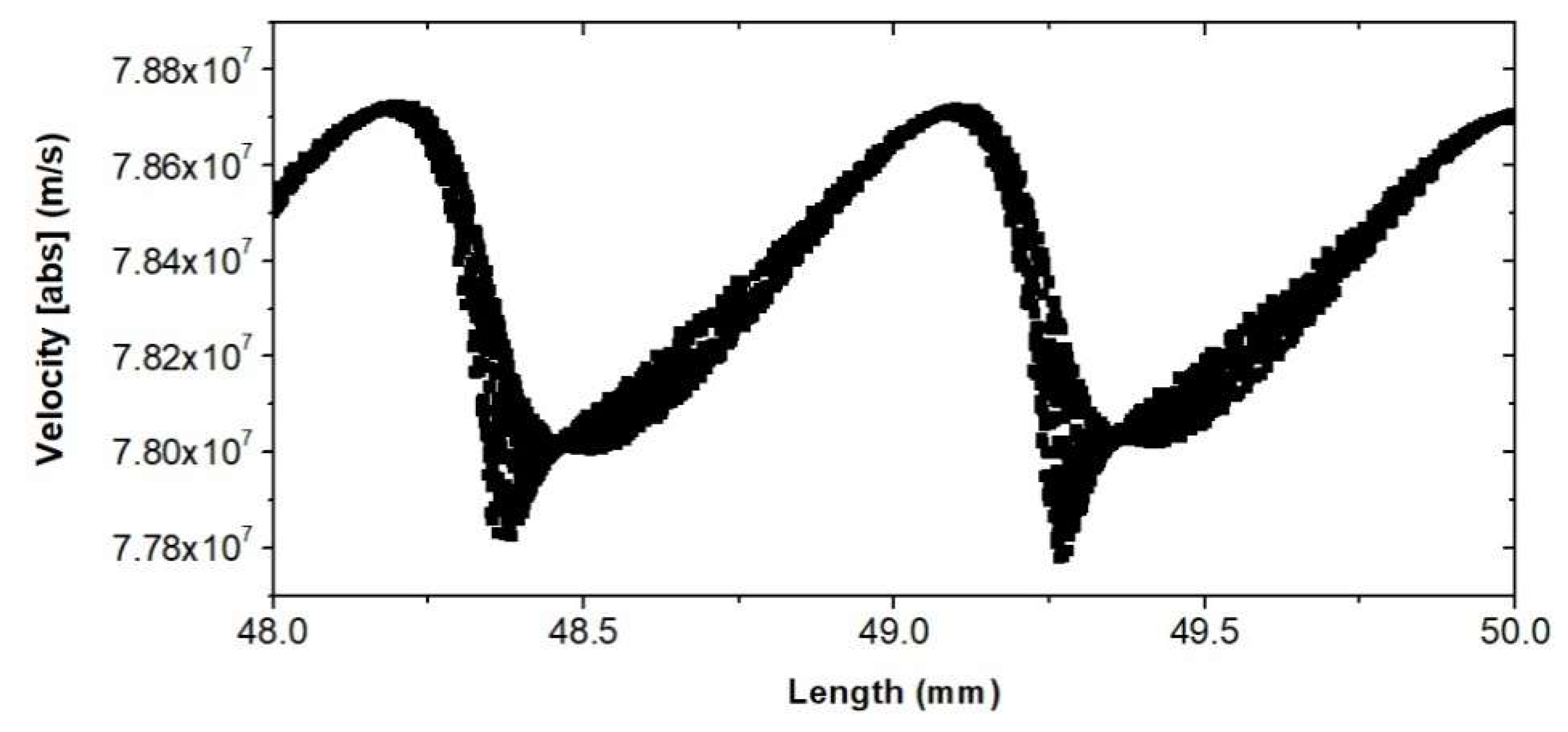
The phase space of beam electron in the modulation section is shown in Figure 3. It shows the amplification process is at linear state before 38 mm. Hence, the length of modulation section is set as 38 mm.
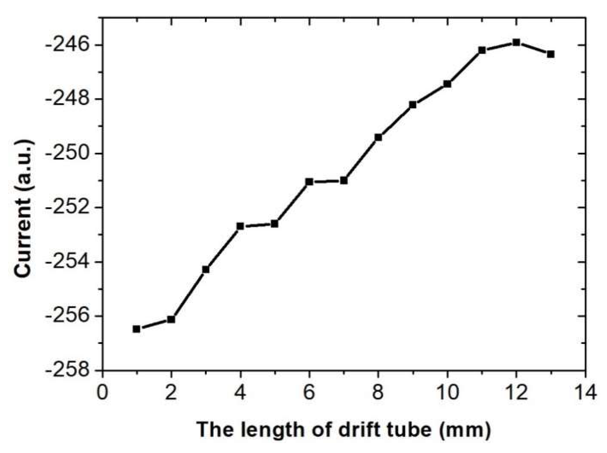
In order to determine the length of the drift tube, a series of current monitors are placed every other millimeter on the drift tube. Figure 4 plots the Fourier transform of the electron current signal at the end of the drift tube. Fundamental component and other three high harmonic components are also shown in it. However, only the fourth harmonic wave can be excited and amplified because the fundamental wave and other lower-order harmonic waves are cut off in the radiation section. In general, the length of the drift tube is controlled at the position where the fourth harmonic current is the largest. Figure 5 depicts the relative amplitude of the fourth harmonic current curve versus the length of the drift tube. The length of the drift tube is determined as 12 mm. Figure 6 shows the phase space graph of the electron beam at the end of the drift tube. It depicts that the electron beam is modulated by EM wave and stay in the linear state. The energy is still stored in the electron beam.
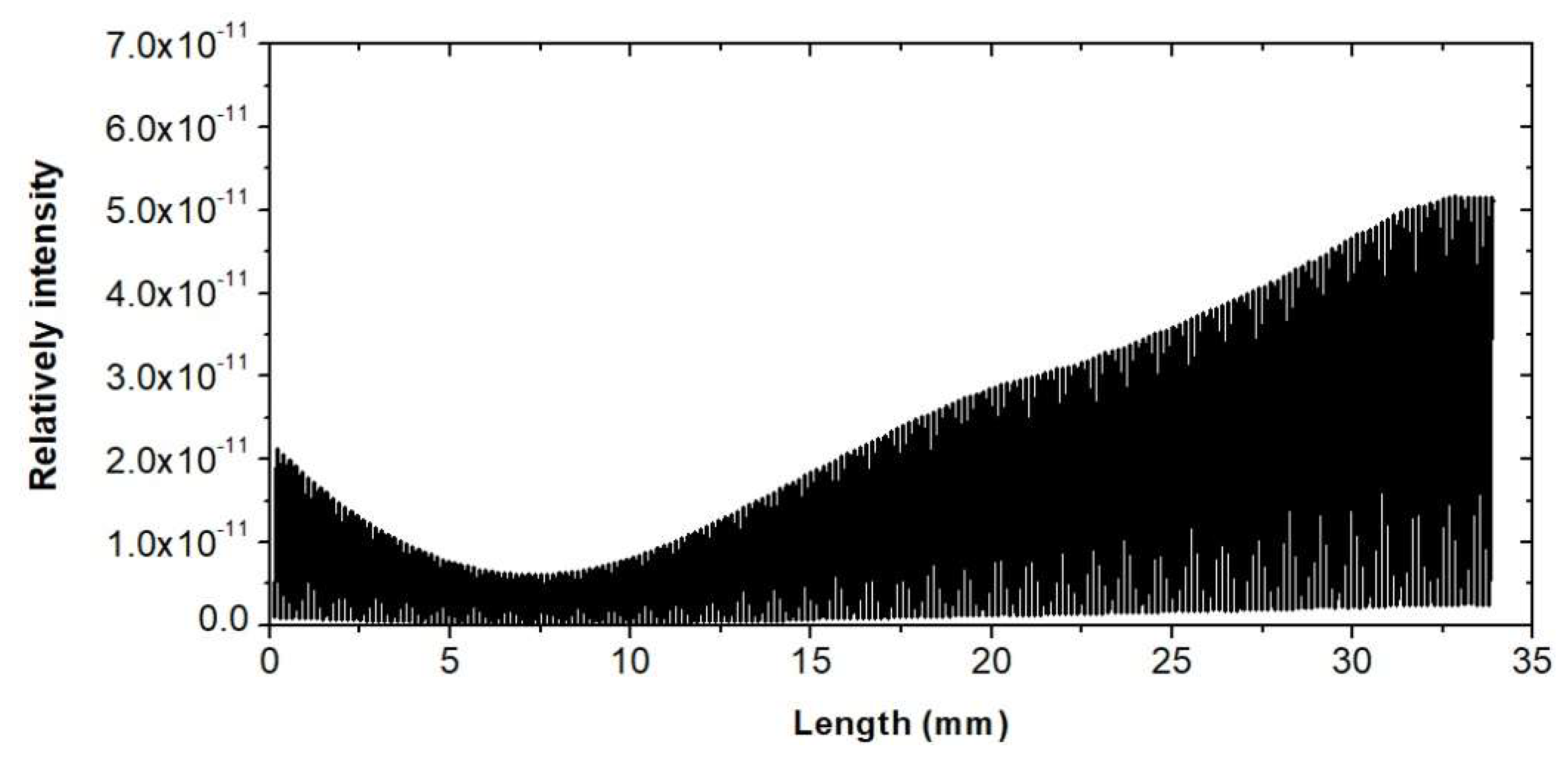
The length of the radiation section is chosen where output power reaches saturation point. Figure 7 shows the power versus the length of the HHTWT at 346 GHz. Hence, the length of the radiation section is 34 mm. The phase space graph of electron beam at the end of radiation section is shown as Figure 8.
Figure 8 shows the fourth harmonic is excited. Compared with Figure 6, the velocity of central cluster decreased significantly in Figure 8. It means the electron beam transfers a lot of energy to the EM wave, during the beam wave interaction in the radiation section. For convenience of reference, the parameters of HHTWT are summarized in Table 2.
2.3. The Simulation Results
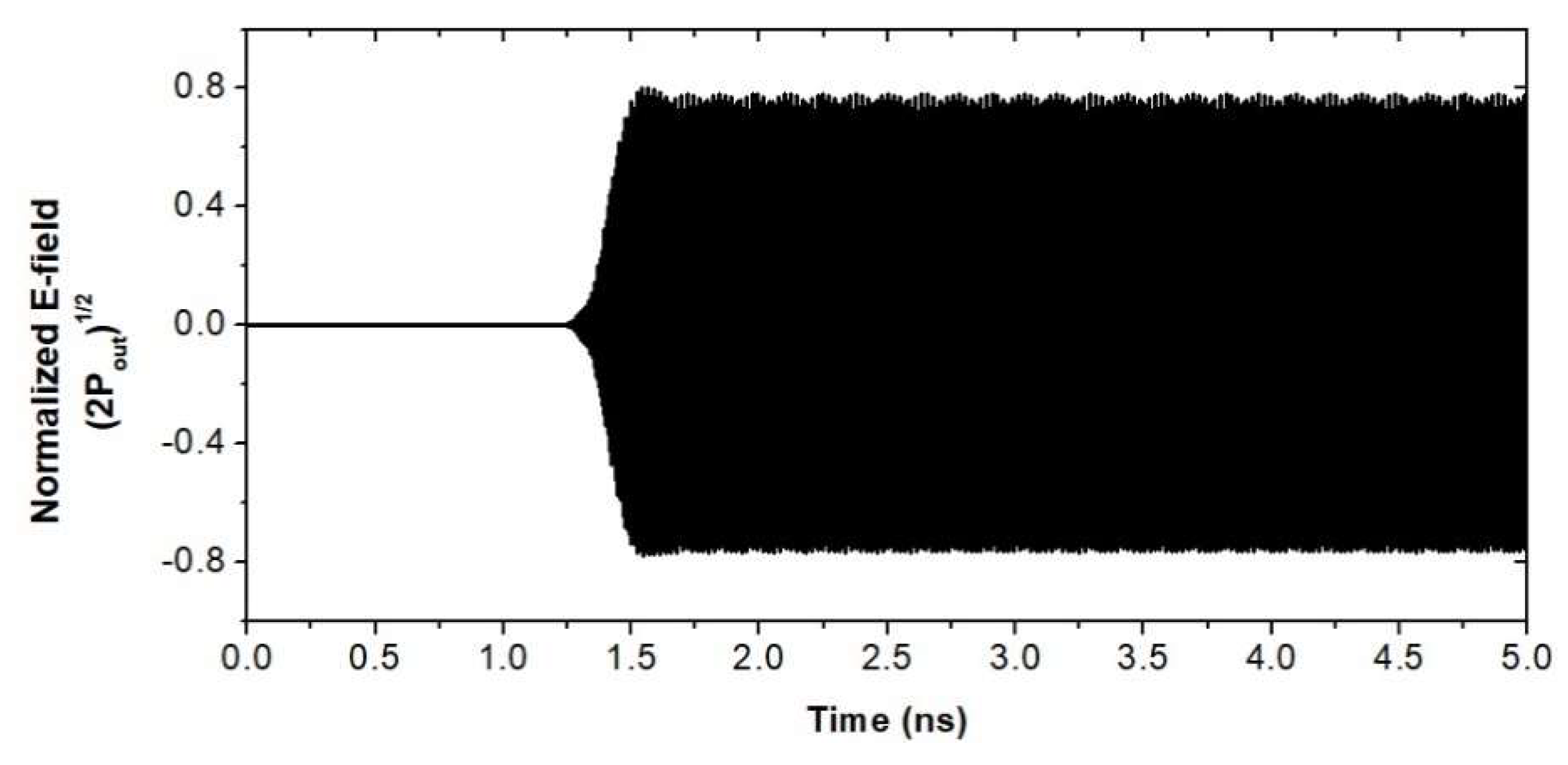
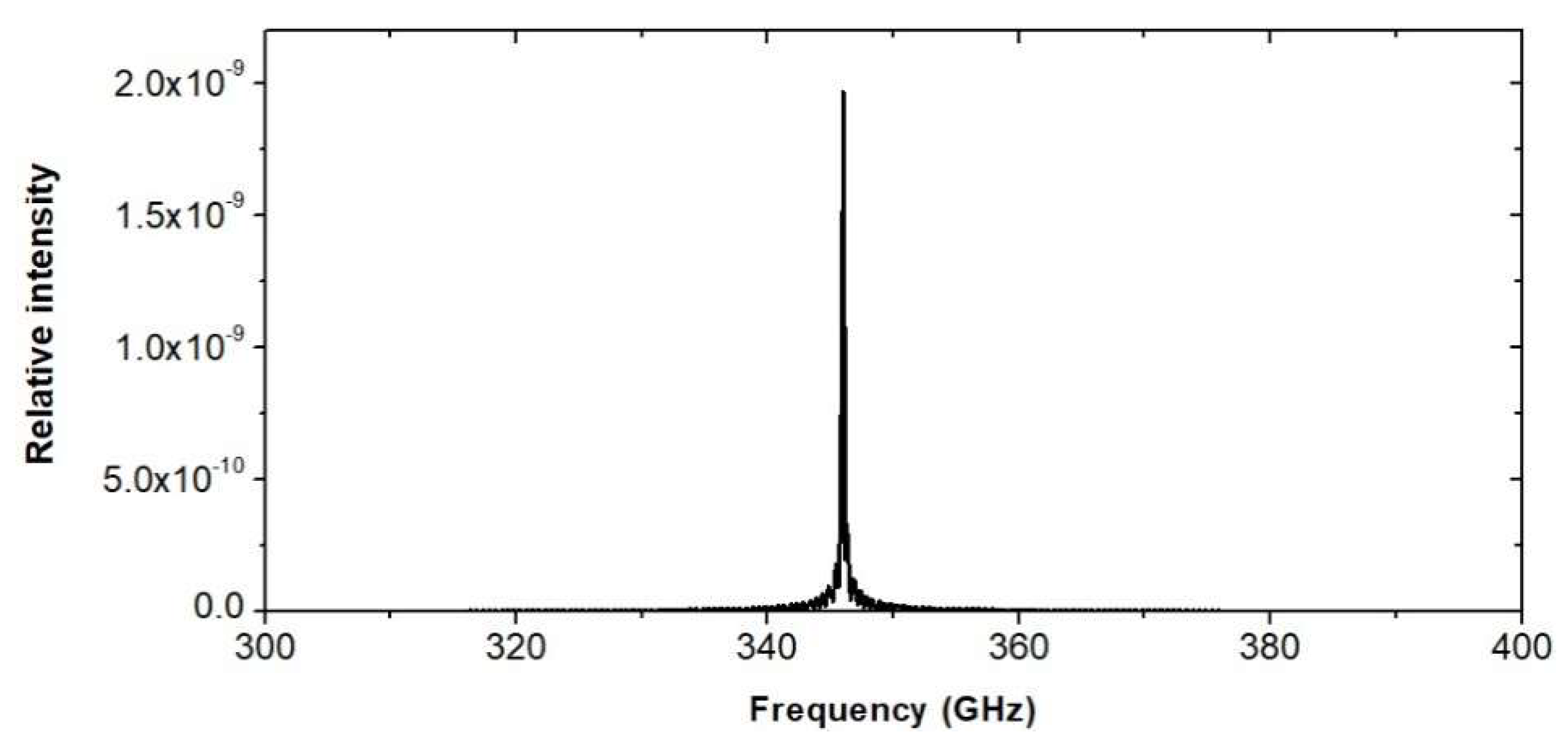
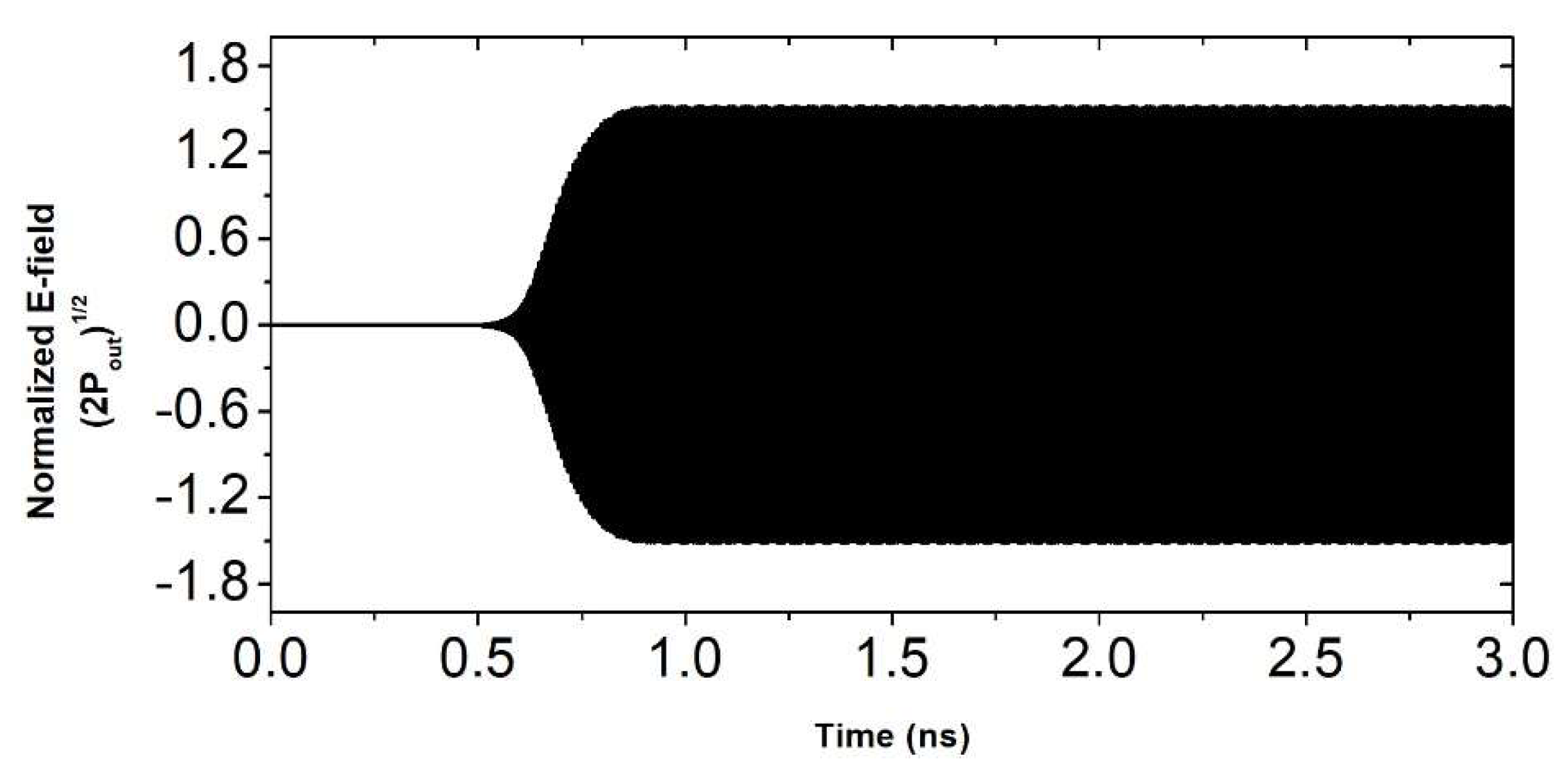
The output power of the HHTWT is shown in Figure 9. It can deliver about 300 mW at 346 GHz. As illustrated in Figure 10, the spectrum of the output power is concentrated at 346 GHz. Figure 11 plots the output power from 340 to 348 GHz. When 200-mW signal is input from 85 to 87 GHz, over 100-mW power can be delivered with the 8-GHz bandwidth.
3. Cascaded Enhanced HHTWT
3.1. Operating Principle of CE-HHTWT
In order to amplify the power of HHTWT, a novel structure is proposed on the basis of HHTWT, named cascaded enhanced HHTWT. It is featured by introduction of another electron beam that forms dual-beam THz band CE-HHTWT.
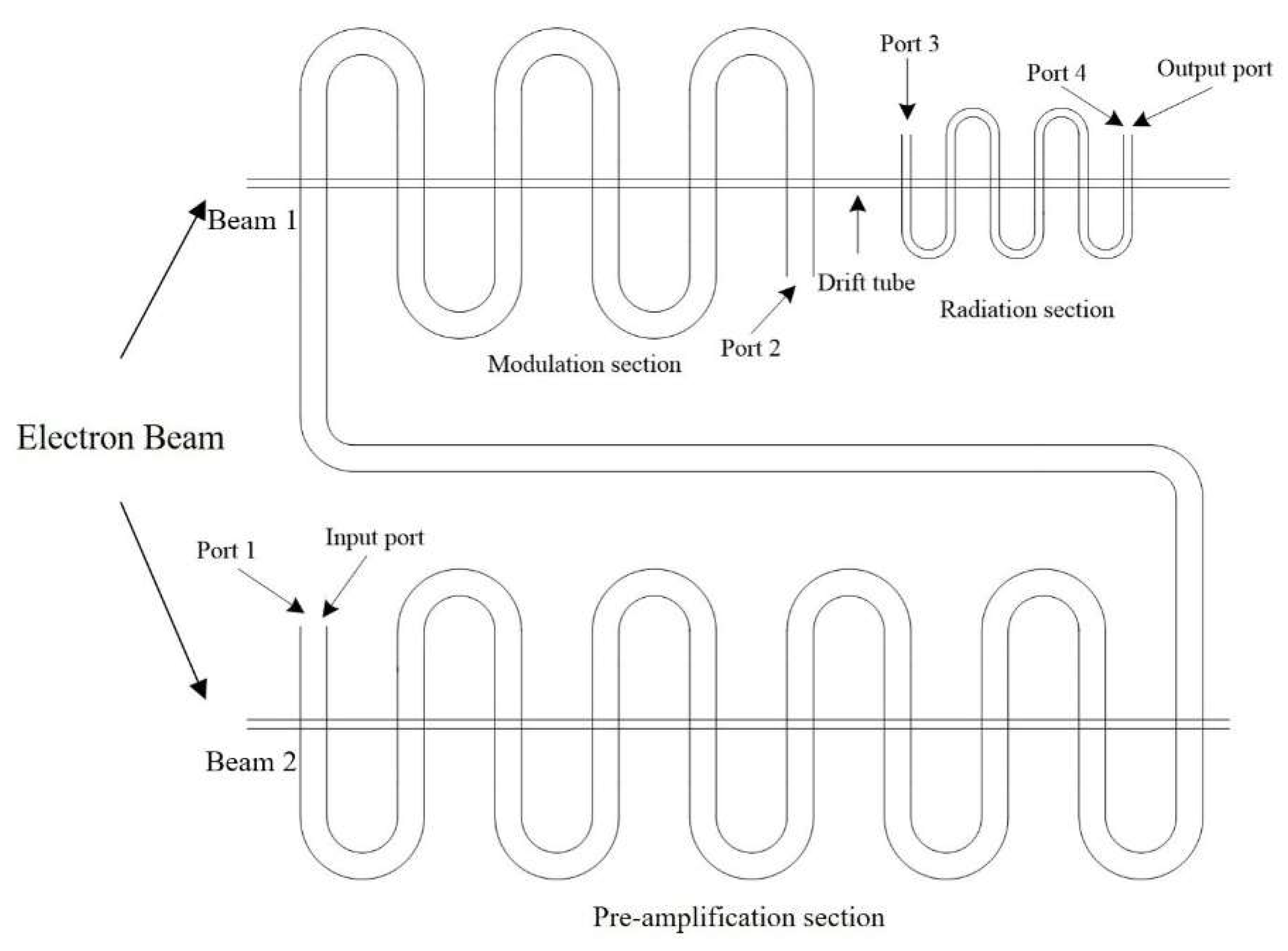
CE-HHTWT is demonstrated in Figure 12. Connecting an amplification section to the output port of the HHTWT forms dual-beam THz band CE-HHTWT. The THz signal enters the amplification section from the radiation section. Beam-wave interaction occurs between a new electron beam and input signal of amplification section. Compared with the HHTWT, the efficiency and the output power of dual-beam CE-HHTWT is improved.
3.2. SWS Design Methodology of CE-HHTWT
As shown in Figure 12, the amplification section operates at THz band. To simplify design and fabrication, the amplification utilizes the radiation section with the same structural parameters as SWS does. The parameters of two electron beams in CE-HHTWT are the same with those in HHTWT.
The length of the amplification section is chosen where the output power reaches saturation point. Figure 13 shows the power curve versus the length of the amplification section at 346 GHz. Hence, the length of the amplification section is 34 mm. The parameters of CE-HHTWT are summarized in Table 3.
3.3. The Simulation Results
The output power of the CE-HHTWT is shown in Figure 14. The input signal is 200 mW at 86.5 GHz. Furthermore, a signal of 1100 mW is obtained at 346 GHz.
Figure 15 is the Fourier transform of signal at end of the amplification section. The spectrum of the output signal is concentrated at the frequency of 346 GHz.
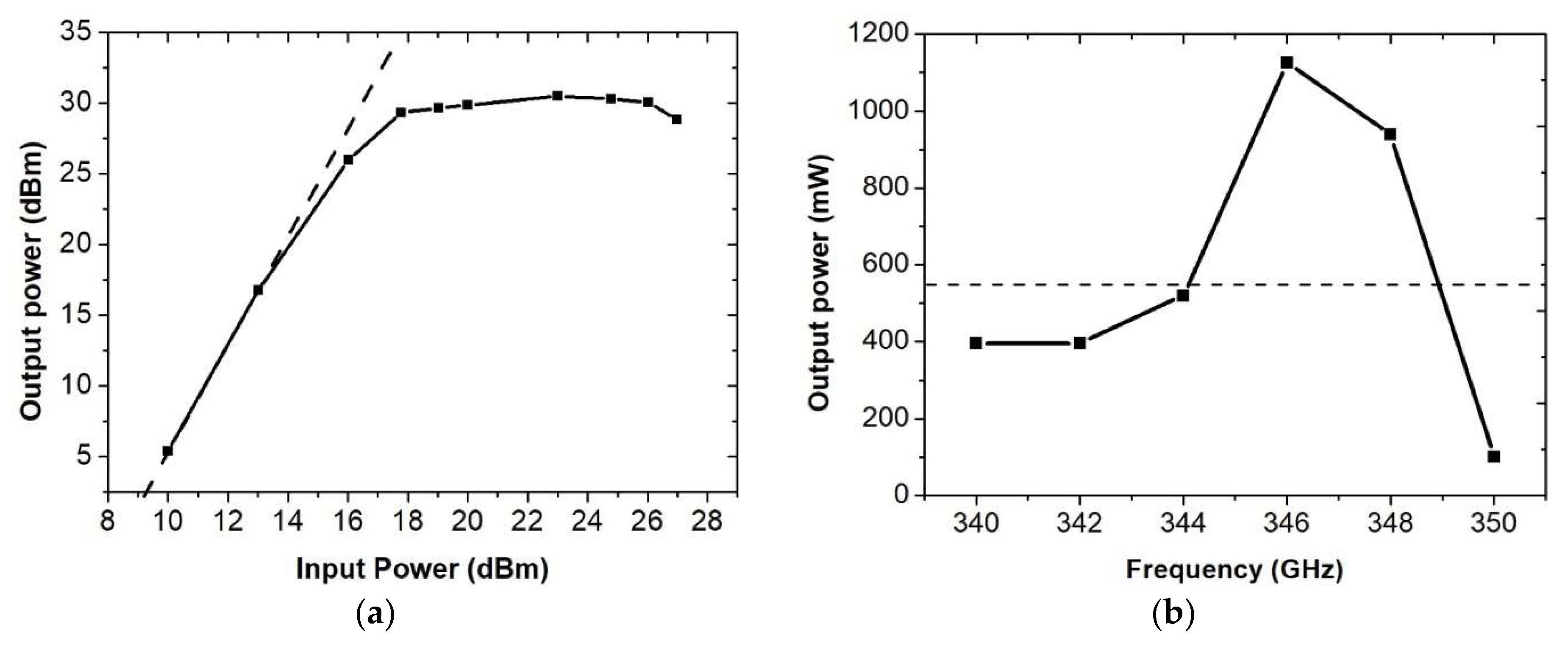
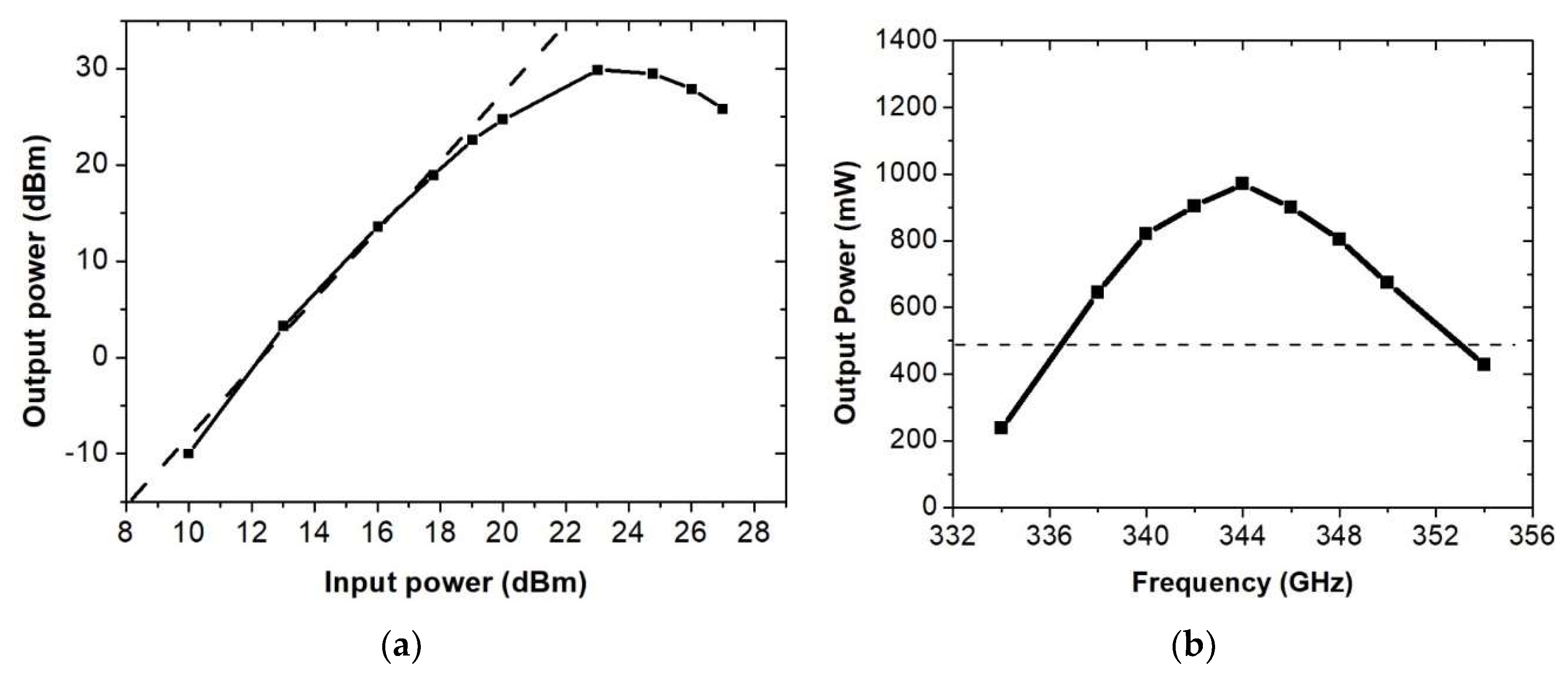
Figure 16 shows the gain property and bandwidth property of CE-HHTWT. At 346 GHz, the output power is saturated when the input power is 200 mW. Figure 16b shows that more than 400 mW output power could be achieved from 340 to 348 GHz. The maximum power is 1100 mW at 346 GHz. The 3-dB bandwidth of CE-HHTWT is 5 GHz.
4. Pre-Amplified HHTWT
4.1. Operating Principle of PA-HHTWT
The PA-HHTWT is presented in Figure 17. A pre-amplification section is connected to the input port of a HHTWT, which constitute the other new TWT. Fundamental signal is amplified by an electron beam firstly. Then, as an input signal, the amplified fundamental signal interacts with a new electron beam to generate the THz signal in the HHTWT.
In comparison with HHTWT and PA-HHTWT, the electron beam is deeply modulated. Hence, it can improve the output power.
4.2. SWS Design Methodology of PA-HHTWT
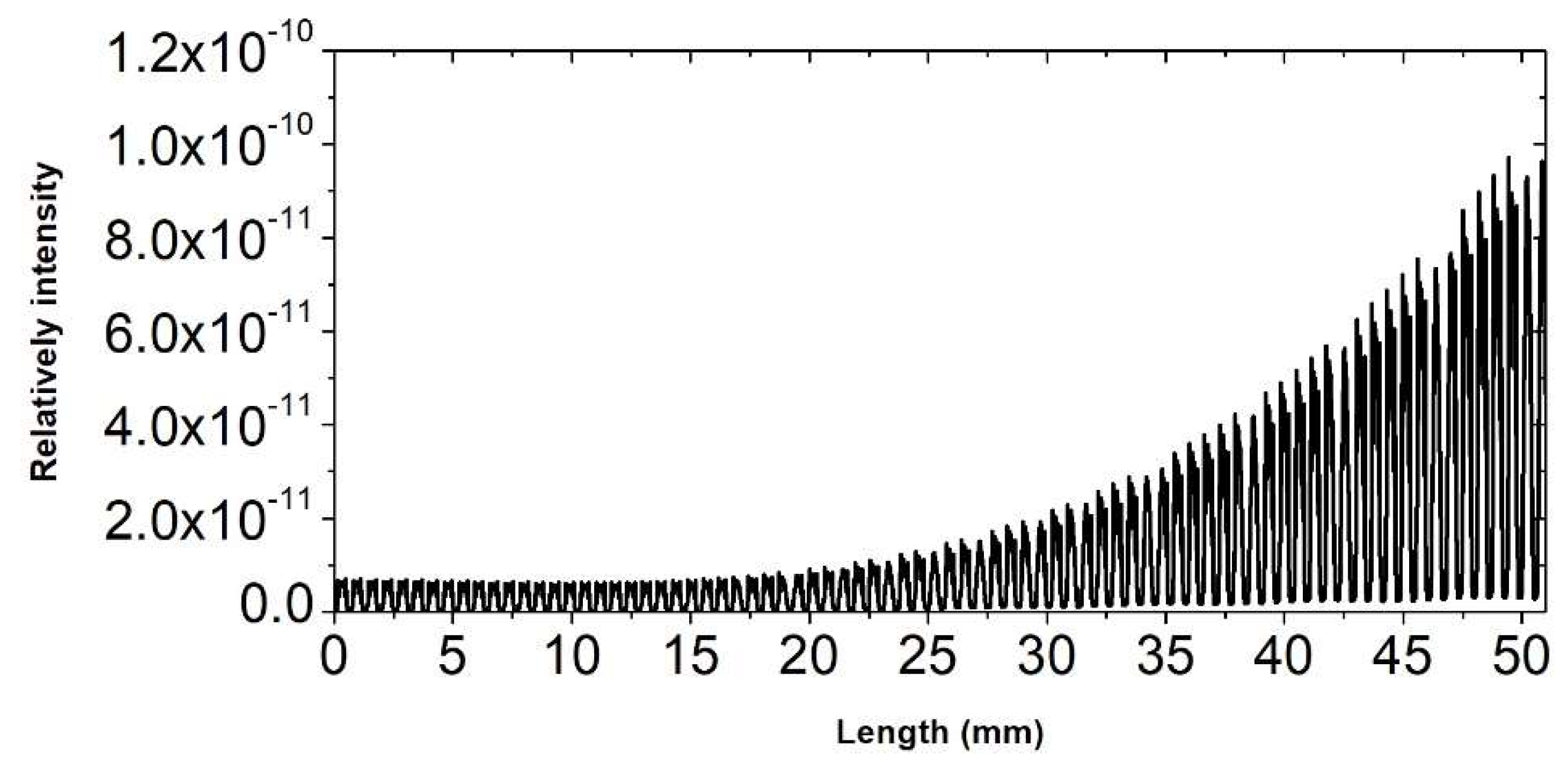
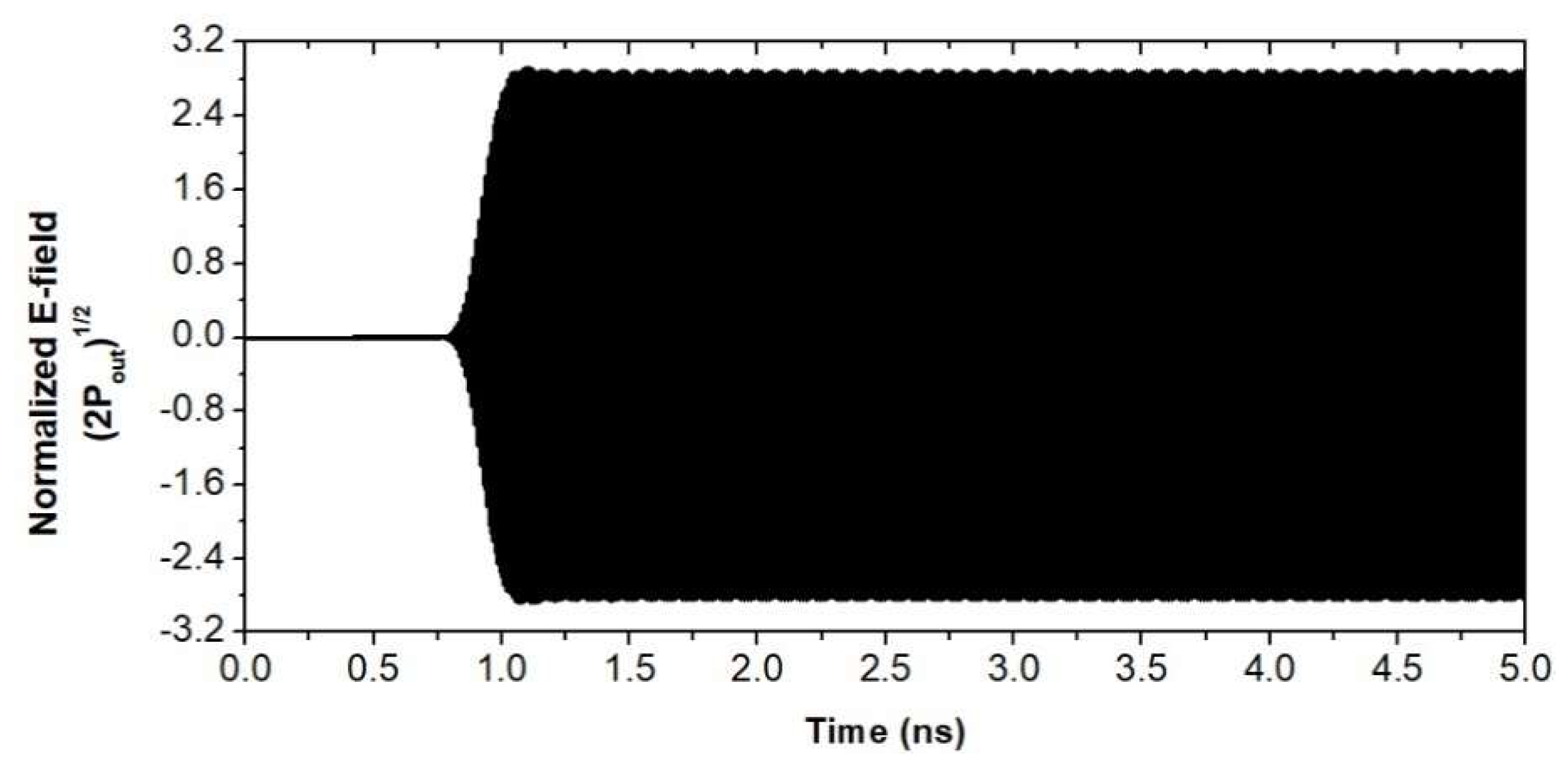
For the PA-HHTWT, the pre-amplification section plays a role in amplifying the fundamental wave to several-watts level. The pre-amplification section utilizes the same structural parameters with modulation section. The length of pre-amplification section is set as 51 mm. The power versus axial length curve and the output signal are shown in Figure 18 and Figure 19, respectively. The input power is set at 200 mW and then 4.5-W output power is obtained.
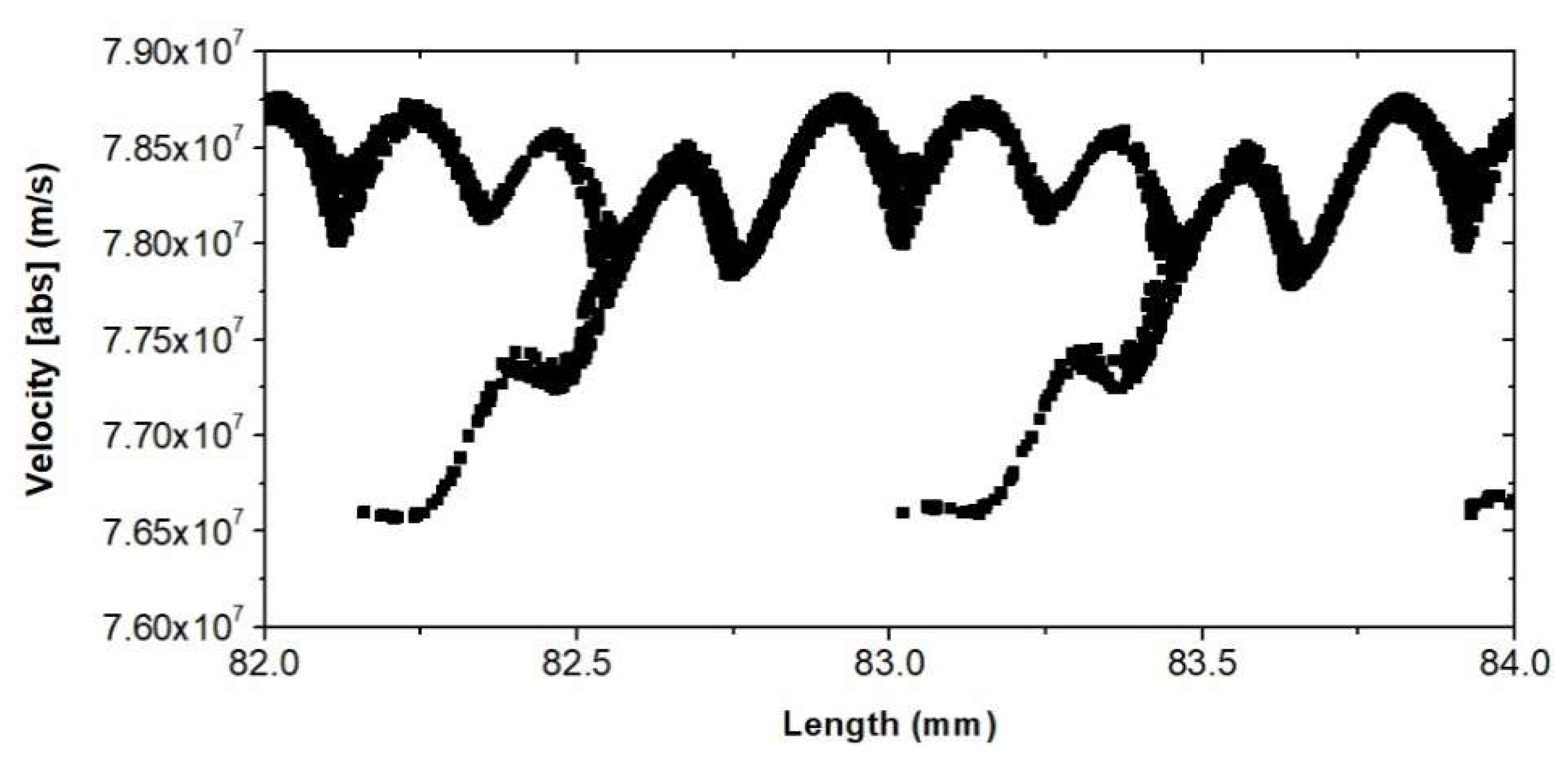
The length of the modulation section is chosen to make the energy modulate the beam as deeply as possible, rather than amplify the EM wave. Figure 20 depicts the input and output signal of the modulation section at 86.5 GHz. When the length of the modulation section is 20.48 mm, the output power is barely higher than the input power, because the energy of electron beam is almost not changed within the modulation process. The behavior mentioned above is also validated in Figure 21. The electron beam is modulated more deeply than HHTWT and CE-HHTWT. Meanwhile, there is no obvious nonlinear characteristic.
The method to determine the length of the drift tube and the radiation section is similar to that in the HHTWT and CE-HHTWT. Eventually, the length of the drift tube and the radiation section are chosen at 4 mm and 10.2 mm, respectively. For convenience, the parameters of PA-HHTWT are shown in Table 4.
4.3. The Simulation Results
5. Conclusions
To develop high-power THz sources, HHTWT operating at 346 GHz is introduced and analyzed in this paper. It can output THz signal by amplifying the fourth harmonic component of E-band RF signal. The simulation results demonstrate that amplifying the fourth harmonic signal is a promising way to obtain high-power THz signal. Furthermore, two power-enhanced schemes, CE-HHTWT and PA-HHTWT, are proposed in this paper. CE-HHTWT yields the THz power by amplifying the signal generated by HHTWT. PA-HHTWT amplifies THz band EM wave by importing high power-level fundamental wave into HHTWT. The operating principle and design methodology of two schemes are also described in this paper, including high frequency characteristics and length determination of each sections. To validate working principle which relies upon Pierce’s linear theory, the simulation results are predicted by CST. Driven by two 18.4 kV,10 mW electron beams, CE-HHTWT can generate over 400 mW power in 340–348 GHz by inputting signal of 200 mW from 85 GHz to 87 GHz. The peak power is 1100 mW at 346 GHz. The output power of PA-HHTWT is over 600 mW in 338–350 GHz. The 3 dB bandwidth reaches 16.5 GHz. The simulation results show that CE-HHTWT and PA-HHTWT have advantages in peak power and wide bandwidth, respectively. Compared with conventional THz sources driven by high-power solid-state power amplifier, these two schemes, both constituted by two TWTs, have superiorities in structural strength and costs.
In future study, CE-HHTWT and PA-HHTWT SWSs can be fabricated by using high-precision CNC milling. Periodic permanent magnet (PPM) and dual-beam electron gun will be adopted in electron optical system. To validate the feasibility of design, the insertion loss, output power, bandwidth, and phase noise characters will be tested. Thus, the schemes of CE-HHTWT and PA-HHTWT are hopeful approaches to realize practical high-power THz sources for plasma diagnostic, communication, and radar.
Author Contributions
Conceptualization, R.Z., H.G., and Q.W.; methodology, R.Z. and H.G.; software, R.Z. and D.D.; validation, R.Z. and Y.D.; formal analysis, R.Z. and H.G.; investigation, R.Z., G.T., and H.G.; writing—original draft preparation, R.Z.; writing—review and editing, R.Z. and F.X. All authors have read and agreed to the published version of the manuscript.
Funding
This work was supported in part by the National Natural Science Foundation of China under Grant 61370152, 61531010 and in part by the American Physical Society’s International Travel Grant Award Program.
Conflicts of Interest
The authors declare no conflict of interest.
References
- Booske, J. Vacuum electronic sources for high power terahertz-regime radiation. In Proceedings of the 2011 IEEE International Vacuum Electronics Conference (IVEC), Bangalore, India, 21–24 February 2011; p. 11. [Google Scholar] [CrossRef]
- Bates, D.J.; Ginzton, E.L. A traveling-wave frequency multiplier. Proc. IRE 1957, 45, 938–944. [Google Scholar] [CrossRef]
- Liu, S.; Zhong, R. Recent development of terahertz science and its applications. J. Univ. Electron. Sci. Technol. China 2009, 38, 481–486. [Google Scholar]
- Wang, W. Microwave Engineering Technology, 2nd ed.; National Defense Industry Press: Beijing, China, 2009. [Google Scholar]
- Karetnikova, T.A.; Ryskin, N.M.; Belov, K.V.; Ploskih, A.E. Simulation of a 0.2 thz second-harmonic multiplier with sheet electron beam. In Proceedings of the 2017 10th UK-Europe-China Workshop on Millimetre Waves and Terahertz Technologies (UCMMT), Liverpool, UK, 11–13 September 2017; pp. 1–2. [Google Scholar] [CrossRef]
- Gong, H.; Travish, G.; Xu, J.; Wei, Y.; Feng, J.; Gong, Y. High-power tunable terahertz radiation by high-order harmonic generation. IEEE Trans. Electron Devices 2013, 60, 482–486. [Google Scholar] [CrossRef]
- Zhang, C. Research on High-Power Millimeter-Wave Folded Waveguide Traveling Wave Tube. Ph.D. Thesis, University of Electronic Science and Technology of China, Chengdu, China, 2011. [Google Scholar]
- Stuart, R.A.; Wright, C.C.; Al-shamma’a, A.I. Compact tuneable terahertz source. In Proceedings of the 2006 European Microwave Conference, Manchester, UK, 10–15 September 2006; pp. 322–324. [Google Scholar] [CrossRef]
- Nguyen, K.; Ludeking, L.; Pasour, J.; Pershing, D.; Wright, E.; Abe, D.K.; Levush, B. Design of a high-gain wideband high-power 220-GHz multiple-beam serpentine TWT. In Proceedings of the 2010 IEEE International Vacuum Electronics Conference, Monterey, CA, USA, 18–20 May 2010; pp. 23–24. [Google Scholar] [CrossRef]
- Galdetskiy, A.V.; Golenitskiy, I.I.; Myakinkov, V.U.; Negirev, A.A.; Rudy, U.B. On power consumption reduction in 700 GHz BWO. In Proceedings of the 2011 IEEE International Vacuum Electronics Conference, Bangalore, India, 21–24 February 2011; pp. 57–58. [Google Scholar] [CrossRef]
- Paoloni, C.; Mineo, M.; Di Carlo, A.; Durand, A.J.; Krozer, V.; Kotiranta, M. 1-thz cascade backward wave amplifier. In Proceedings of the IVEC 2012, Monterey, CA, USA, 24–26 April 2012; pp. 237–238. [Google Scholar] [CrossRef]
- Tucek, J.C.; Basten, M.A.; Gallagher, D.A.; Kreischer, K.E.; Lai, R.; Radisic, V.; Leong, K.; Mihailovich, R.A. 100 mw, 0.670 thz power module. In Proceedings of the IVEC 2012, Monterey, CA, USA, 24–26 April 2012; pp. 31–32. [Google Scholar] [CrossRef]
- Tucek, J.C.; Basten, M.A.; Gallagher, D.A.; Kreischer, K.E. 0.850 thz vacuum electronic power amplifier. In Proceedings of the IEEE International Vacuum Electronics Conference, Monterey, CA, USA, 22–24 April 2014; pp. 153–154. [Google Scholar] [CrossRef]
- Tucek, J.C.; Basten, M.A.; Gallagher, D.A.; Kreischer, K.E. Operation of a compact 1.03 thz power amplifier. In Proceedings of the IEEE International Vacuum Electronics Conference (IVEC), Monterey, CA, USA, 19–21 April 2016; pp. 1–2. [Google Scholar] [CrossRef]
- Armstrong, C.M.; Kowalczyk, R.; Zubyk, A.; Berg, K.; Meadows, C.; Chan, D.; Schoemehl, T.; Duggal, R.; Hinch, N.; True, R.B.; et al. A Compact Extremely High Frequency MPM Power Amplifier. IEEE Trans. Electron Devices 2018, 65, 2183–2188. [Google Scholar] [CrossRef]
- Pan, P.; Tang, Y.; Bian, X.; Zhang, L.; Lu, Q.; Li, Y.; Feng, Y.; Feng, J. A G-Band Traveling Wave Tube With 20 W Continuous Wave Output Power. IEEE Electron Device Lett. 2020, 41, 1833–1836. [Google Scholar] [CrossRef]
- Lee, K.C.; Domier, C.W.; Johnson, M.; Luhmann, N.C.; Park, H. FIR laser tangential interferometry/polarimetry on NSTX. IEEE Trans. Plasma Sci. 2004, 32, 1721–1726. [Google Scholar] [CrossRef]
- Paoloni, C.; Gamzina, D.; Himes, L.; Popovic, B.; Barchfeld, R.; Yue, L.; Zheng, Y.; Tang, X.; Tang, Y.; Pan, P.; et al. THz Backward-Wave Oscillators for Plasma Diagnostic in Nuclear Fusion. IEEE Trans. Plasma Sci. 2016, 44, 369–376. [Google Scholar] [CrossRef] [Green Version]
- Feng, J.; Tang, Y.; Gamzina, D.; Li, X.; Popovic, B.; Gonzalez, M.; Himes, L.; Barchfeld, R.; Li, H.; Pan, P.; et al. Fabrication of a 0.346-THz BWO for Plasma Diagnostics. IEEE Trans. Electron Devices 2018, 65, 2156–2163. [Google Scholar] [CrossRef]
- Krupnov, A.F. Phase Lock-In of MM/SUBMM Backward Wave Oscillators: Development, Evolution, and Applications. Int. J. Infrared Millim. Waves 2001, 22, 1–18. [Google Scholar] [CrossRef]
- Gong, H.; Wang, Q.; Deng, D.; Dong, Y.; Xu, J.; Tang, T.; Su, X.; Wang, Z.; Gong, Y.; Travish, G. Third-harmonic traveling-wave tube multiplier-amplifier. IEEE Trans. Electron Devices 2018, 65, 2189–2194. [Google Scholar] [CrossRef]
- Gamzina, D.; Li, H.; Himes, L.; Barchfeld, R.; Popovic, B.; Pan, P.; Letizia, R.; Mineo, M.; Feng, J.; Paoloni, C.; et al. Nanoscale Surface Roughness Effects on THz Vacuum Electron Device Performance. IEEE Trans. Nanotechnol. 2016, 15, 85–93. [Google Scholar] [CrossRef] [Green Version]
- Pan, P.; Li, H.; Feng, J. Study on loss of folded waveguide structures of 220 GHz and 340 GHz. In Proceedings of the 2016 IEEE International Vacuum Electronics Conference (IVEC), Monterey, CA, USA, 19–21 April 2016; pp. 1–2. [Google Scholar] [CrossRef]
Figure 1.
The slow wave structure (SWS) of high-harmonic traveling wave tube (HHTWT).

Figure 2.
High frequency characteristics of the modulation and the radiation section. (a) The modulation section; (b) the radiation section.
Figure 2.
High frequency characteristics of the modulation and the radiation section. (a) The modulation section; (b) the radiation section.

Figure 3.
The phase space graph of the electron beam in the modulation section.

Figure 4.
The Fourier transform of the electronic current signal.

Figure 5.
The graph of amplitude of the fourth harmonic.

Figure 6.
The phase space graph of electron beam at the end of drift tube.

Figure 7.
Power curve of the HHTWT at 346 GHz.

Figure 8.
The phase space graph of the electron beam at the end of the radiation section.

Figure 9.
The output signal of the HHTWT at 346 GHz.

Figure 10.
The Fourier transform of output signal at 346 GHz.

Figure 11.
Output power of HHTWT.

Figure 12.
The SWS of the dual-beam CE-HHTWT.

Figure 13.
Power curve of the amplification section.

Figure 14.
The output signal of the CE-HHTWT at 346 GHz.

Figure 15.
The Fourier transform of output signal.

Figure 16.
Gain property (a) and bandwidth property (b) of CE-HHTWT.

Figure 17.
The SWS of dual beam PA-HHTWT.

Figure 18.
Power curve of the pre-amplification section.

Figure 19.
Output signal of pre-amplification section.

Figure 20.
Input (red) and output (black) power of the modulation section at 86.5 GHz.

Figure 21.
The phase space graph of electron beam in modulation section of PA-HHTWT.

Figure 22.
The output signal of the PA-HHTWT at 346 GHz.

Figure 23.
The Fourier transform of output signal.

Figure 24.
Gain property (a) and bandwidth property (b) of PA-HHTWT.


Table 1.
Structural parameters of the HHTWT.
| Parameters | Modulation Section | Radiation Section | Drift Tube |
|---|---|---|---|
| a | 2 mm | 0.5 mm | / |
| b | 0.32 mm | 0.085 mm | / |
| p | 0.64 mm | 0.17 mm | / |
| h | 0.51 mm | 0.2 mm | / |
| r | 0.08 mm | 0.08 mm | 0.08 mm |
Table 2.
Parameters of the HHTWT.
| Parameters | Values |
|---|---|
| Beam voltage | 18.4 kV |
| Beam current | 10 mA |
| Beam radius | 0.04 mm |
| Length of modulation section | 38 mm |
| Length of drift tube | 12 mm |
| Length of radiation section | 34 mm |
Table 3.
Parameters of the CE-HHTWT.
| Parameters | Values |
|---|---|
| Beam voltage of beam 1 and 2 | 18.4 kV |
| Beam current of beam 1 and 2 | 10 mA |
| Beam radius | 0.04 mm |
| Length of modulation section | 38 mm |
| Length of drift tube | 12 mm |
| Length of radiation section | 34 mm |
| Length of amplification section | 34 mm |
Table 4.
Parameters of the PA-HHTWT.
| Parameters | Values |
|---|---|
| Beam voltage of beam 1 and 2 | 18.4 kV |
| Beam current of beam 1 and 2 | 10 mA |
| Beam radius | 0.04 mm |
| Length of pre-amplification section | 51 mm |
| Length of modulation section | 20.5 mm |
| Length of drift tube | 4 mm |
| Length of radiation section | 10.2 mm |
Publisher’s Note: MDPI stays neutral with regard to jurisdictional claims in published maps and institutional affiliations. |
© 2021 by the authors. Licensee MDPI, Basel, Switzerland. This article is an open access article distributed under the terms and conditions of the Creative Commons Attribution (CC BY) license (http://creativecommons.org/licenses/by/4.0/).
Share and Cite
MDPI and ACS Style
Zhang, R.; Wang, Q.; Deng, D.; Dong, Y.; Xiao, F.; Travish, G.; Gong, H. Novel Dual Beam Cascaded Schemes for 346 GHz Harmonic-Enhanced TWTs. Electronics 2021, 10, 195. https://doi.org/10.3390/electronics10020195
AMA Style
Zhang R, Wang Q, Deng D, Dong Y, Xiao F, Travish G, Gong H. Novel Dual Beam Cascaded Schemes for 346 GHz Harmonic-Enhanced TWTs. Electronics. 2021; 10(2):195. https://doi.org/10.3390/electronics10020195
Chicago/Turabian StyleZhang, Ruifeng, Qi Wang, Difu Deng, Yao Dong, Fei Xiao, Gil Travish, and Huarong Gong. 2021. "Novel Dual Beam Cascaded Schemes for 346 GHz Harmonic-Enhanced TWTs" Electronics 10, no. 2: 195. https://doi.org/10.3390/electronics10020195
Note that from the first issue of 2016, this journal uses article numbers instead of page numbers. See further details here.