Multibody Dynamic Analysis of a Wind Turbine Drivetrain in Consideration of the Shaft Bending Effect and a Variable Gear Mesh Including Eccentricity and Nacelle Movement
 Yonghui Park
 Hyunchul Park2
  Jikun You
 Wei Shi
- 1Department of Mechanical Engineering, Yuhan University, Bucheon, Korea
- 2Graduate School of Engineering Mastership, POSTECH , Pohang ,Korea
- 3Deepwater Engineering Research Center, Dalian University of Technology, Dalian, China
- 4Connect LNG AS, Oslo, Norway
- 5State Key Laboratory of Coastal and Offshore Engineering, Dalian University of Technology, Dalian, China
Due to the energy crisis and global warming issues, the wind energy is becoming one of the most attractive renewable energy resources in the world. The drivetrains in the wind turbine tend to fail more prematurely than those in any other applications. Gearbox is the subsystem that causes the most downtime for the wind turbines. In the previous research, only the torsional flexibility of the shaft was considered in the drivetrain model. However, because the shaft is longer than other parts, and components connected by the shaft affect each other via shaft bending, the flexibility of the shaft cannot be ignored. In this study, a spherical joint that consists of three rotational springs was used to define the shaft bending. This shaft bending will affect the drivetrain rotation, the translational motion and the gear mesh contact force. Additionally, the eccentricity and the nacelle movement are analyzed due to the coupled motion. In this paper, a mathematical model of the drivetrain is proposed, which is a three-dimensional dynamic model that includes flexible bearings, a gear mesh model, shaft flexibility, eccentricity, and nacelle movement. The equation of motion of the drivetrain is derived using Lagrange's equation. The governing equation is solved numerically via direct numerical integration. The dynamic responses of the system and contact forces between the gear tooth in the time and frequency domains are calculated numerically. The study shows that this dynamic model of the drivetrain will be highly useful for subsequent studies on the wind turbine condition monitoring.
Introduction
Due to the energy crisis, many countries are attempting to exploit various renewable energies. As one of the promising renewable energy resources, the wind energy is increasingly attracting more attention. The wind turbine, which is a physical system to convert the kinetic energy of the wind into the electrical energy, is typically composed of the blades, drivetrain, tower and the foundation. The drivetrain of the wind turbine tends to fail more prematurely than those in any other applications. Of all the components of wind turbines, high failure rates of gearbox components have been observed in the wind industry since its inception (Bhardwaj et al., 2019). These failures will lead to longer downtime and high maintenance cost. The average rated capacity of newly installed wind turbine has grown to 7.8 MW and the rotor diameter of turbine rotor reaches up to 164 m by 2019 (European Wind Energy Association, 2020). Many studies have been conducted to deeply investigate the dynamic response of the drivetrain system (Nejad et al., 2014; Nejad et al., 2016). Using the finite element method and multibody dynamic system, Dong et al. (2014) analyzed the gear contact fatigue in the drivetrain with a decoupled analysis approach. Xing and Moan (2013) found out that the main shaft non-torque loads can contribute to the bearing loads and gear displacements. Jiang et al. (2015) used the integrated analysis for the contact fatigue analysis of planetary gear pairs. Kumar and Roy (2020) incorporated mesh phasing and effect of damping in the mathematical model of the wind turbine drivetrain. Tan et al. (2019) considered the platform motion for the planetary geared rotor systems in offshore wind turbines and found the platform motions not only introduce additional excitation frequencies to the drivetrain and increase system vibration but also increase the risk of the resonance. Li et al. (2020) developed an integrated drivetrain coupling analysis model including non-torque loads, which lead to a non-uniform planet load sharing. Yu et al. (2017) considered local tooth profile errors and global mounting errors to investigate the dynamic behavior of a cylindrical gear system. Shi et al. (2018))mathematically investigated the shaft bending effect on the dynamic response of the wind turbine drivetrain. He et al. (2019) applied the time varying mesh stiffness for two-stage-spur gear model considering the gear eccentricity. Wang et al. (2020) found the gear eccentricity affect the gear meshing, vibration amplitudes and frequency multiplication of the transmission system during the vehicle acceleration process.
In the previous research (Shi et al., 2013), the torsional multibody dynamic model was developed for studying the dynamic behavior of the drivetrain under constant torque. More detailed three dimensional(3D) models (Nejad et al., 2016) were used to investigate the transient response of the drivetrain in consideration of the translational motion of each component. However, rigid shafts were considered in these works. For larger wind turbines ( >10 MW), the deformation of the shafts cannot be ignored for longer shafts. Moreover, rotor eccentricity, which is caused by manufacturing defects, may affect the dynamic behavior of the drivetrain. The nacelle movement may also introduce additional loads on the drivetrain.
In this study, a typical drivetrain with a one-stage planet gear and two-stage parallel gears is considered. A multibody dynamic model is developed in this work and includes a turbine rotor, gearbox components, and a generator. The shaft bending, eccentricity, nacelle movement and varying gear mesh are taken into account in this model. The dynamic analysis is conducted via a rigid multibody modeling approach with discrete flexibility that is based on the Lagrange's formulation. The dynamic responses of the system and the contact forces between the gear-tooth pairs in the time and frequency domains are obtained numerically via the step-by-step Newmark time integration algorithm.
Drivetrain Mathematical Model
Model Overview
A typical wind turbine drivetrain mainly consists of a rotor, a low-speed shaft, a gearbox, a high speed-shaft and a generator. The gearbox typically includes one planetary gear stage and two parallel gear stages (Figure 1). In the previous study (Shi et al., 2013), each component has one DOF, and only the torsional stiffness of the shaft and the gear mesh are considered based on the rotational coordinates. In the present study, the drivetrain is modelled via a 3D rigid multibody dynamic method with a discrete flexibility approach. The time varying gear mesh stiffness between the mating gears, the bearing stiffness, the shaft torsion and bending stiffness, and the kinetic energy that is associated with both orbiting and rotating gears are considered in the mathematical formulation. The eccentricity on the component due to manufacturing defects and nacelle movement is also considered.
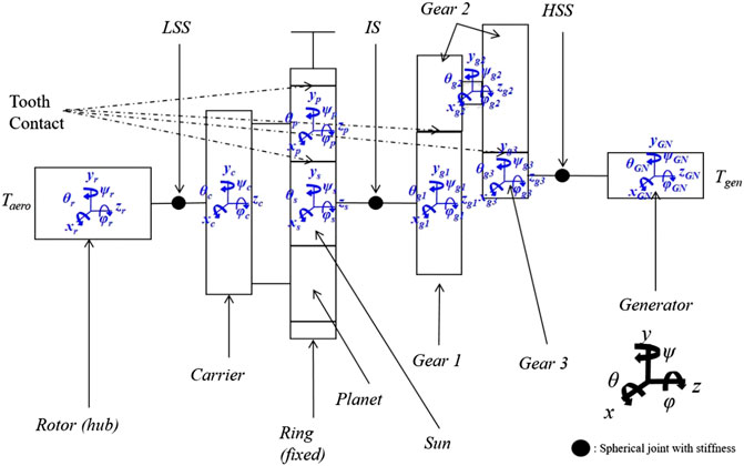
FIGURE 1. Schematic diagram of the wind turbine drivetrain.
Gear Mesh
The gear meshes are modeled with time-varying stiffness. The gear mesh stiffness that varies periodically is represented by Fourier series as a periodic signal in the present study (Lin and Parker, 2002). A similar mesh stiffness is defined for the parallel gear stage. Figure 2 presents an example with varying gear mesh stiffness of the planetary stage and the parallel stages.
where Nr, Ng1, and Ng3 are the gear tooth number of ring gear, gear 1 and gear 3;
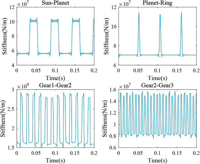
FIGURE 2. Time series of gear mesh stiffness.
Fourier coefficients in Eqs 4, 5 are
where
In previous study, the gear mesh is assumed as a function of constant angular velocity. However, previous model cannot well present the transient effect of the drivetrain system during the wind turbine start-up or emergency stop. In the current model, the gear mesh stiffness is defined as a function of the varying angular displacement with the eighth-order Fourier series (Eq. 6). Table 1 presents the differences between the previous steady gear mesh model and the varying gear mesh model. As discussed previously, the varying gear mesh is a function of the angular displacement. When external torque is applied to the rotor, the angular displacement does not increase steadily. Compared with the steady gear mesh, the varying gear mesh interacts more in terms of the angular displacement. In Table 1, the current angular displacement, velocity, and acceleration are functions of those values from previous time step. Δu, Δv, and Δa are also functions of u, v, and a from the previous time step in the steady gear mesh model. However, these Δ values are not considered exactly. In the Newmark method, each term is determined by a Taylor series, and linearization of the acceleration is assumed. If we use a steady gear mesh, the Newmark conditions are not fully satisfied. Therefore, it is imperative to incorporate the variable gear mesh concept for obtaining an exact solution.
where ω is the angular velocity of the gear and x is the angular displacement of the gear,
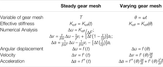
TABLE 1. Comparison of the different gear mesh models.
Figure 3 presents an example of the varying gear mesh stiffness in a wind turbine drivetrain system. This model will be used in the present study.
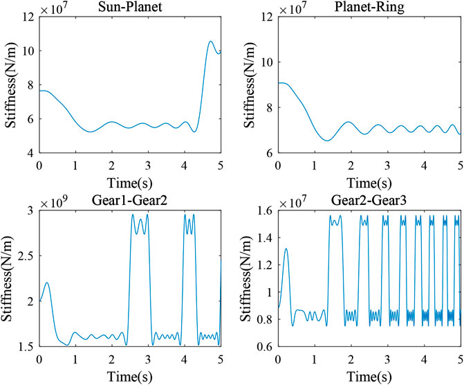
FIGURE 3. Varying gear mesh stiffness model.
Eccentricity
Due to manufacturing defects, not all products can be manufactured perfectly. Due to process limitations, environmental conditions, or human error, eccentricity cannot be effectively avoided for rotational components. In this section, we assume that each component except the generator, has an eccentricity of ei (Figure 4). The rotational displacements in the z-direction between drivetrain models with and without eccentricity are compared. As a typical example in this study, the eccentricity is defined as 20% of each component's radius according to Yassa et al. (2019). Equations 11, 12 present the coordinate of the center of gravity of component i including the eccentricity.
where i = r (rotor), c (carrier), p (planet), s (sun), g1 (gear 1), g2 (gear 2), and g3 (gear 3).
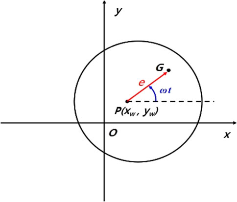
FIGURE 4. Eccentricity of a rigid component.
Nacelle Movement
The previous studies assumed that the drivetrain is fixed in terms of the nacelle and no movement of the nacelle is considered. In this section, nacelle movement is considered using information from Han et al. (2012). In this project, a jacket-type offshore wind turbine was used at 50 m water depth at K13 deep site in the Dutch North Sea. Based on the analysis under operational condition, we could obtain the nacelle's acceleration. The nacelle movement is considered as the inertia force, which is the multiplication of nacelle mass and acceleration (Figure 5). This force will affect the bearings and the shafts. In this work, only the acceleration in the x-direction is considered. A random value with mean acceleration from Han et al. (2012) is used for this inertia force calculation.

FIGURE 5. Illustration of nacelle movement.
Shaft Bending
A shaft can be modeled as a connection of two rigid bodies that have five degrees of freedom, which include bending and torsional displacement, except translational displacement in the z-direction. A spherical joint is adopted to define the shaft bending. The spherical joint provides three generalized coordinates: rotations about the x-, y- and z-axes (Figure 1). In the drivetrain system, the longitudinal extension of the shaft is negligible compared to the rotational deflection and bending. The shaft is defined as two links connected by a spherical joint at the center of the links. Additionally, three springs are designated in the spherical generalized coordinate directions to simulate the shaft's bending deflection characteristics using Timoshenko beam theory (Kim and Yao, 2007; Jiang and Duan, 2011). Using an elastic continuum mechanics and the spring potential energy, Eqs 13, 14 express the potential energy of a Timoshenko beam (Jiang and Duan, 2011). Finally we can obtain shaft bending stiffness by equating Eqs 13, 14. The bending stiffness of the springs in the x and y directions are obtained from Eqs 15, 16.
where As is the sectional area, δ is number of beam division, and L is the beam length.
Equation of Motion
As shown in Figure 1, the wind turbine drivetrain is composed of a rotor, a carrier, a planetary stage, two parallel stages, and a generator. Each component is considered as a rigid body (Shabana, 1994; Lee et al., 2002; Shlecht et al., 2006; Van der Linden and de Souza Silva, 2009; Wang et al., 2009; Chopra, 2011). Various system properties, including the mass, the moment of inertia, and the stiffness, were obtained from previous work (Shi et al., 2013). The equation of motion is presented in terms of the mass, stiffness, and damping matrices.
In this paper, Lagrange's equation was used to derive the equation of motion (EOM) (Bathe, 2006; Craig and Kurdila, 2006). Regarding to the system properties, the varying gear mesh stiffness is used. We reflected these changes in the stiffness matrix. The relative displacements are given in Eqs 17–23.
Equations 24, 25 express the total kinetic and potential energy of the system, respectively. The eccentricity mass in the kinetic energy term can be expressed as the percentage of the radius. kb represents spring stiffness about the x and y directions of each component.
Using the kinetic and potential energy, we can derive Lagrange's equation and the equation of motion (Eqs 26,27). Vector Q is a vector of generalized forces. The gravity and non-linear terms are included in vector Q in Eq. 28.
where T, kinetic energy; V, potential energy.
where
Simulation
Numerical Analysis
The Newmark-β method is used to solve the equation of motion (Eq. 28). This method assumes that the accelerations between consecutive times are constant (Kim et al., 2013). Under this assumption, the displacement and velocity at t + Δt can be determined with Eqs 29, 30:
The parameters α, and β represent how the acceleration affects the velocity and the displacement at time Δt. In this study, we set α = 1/4 and β = 1/2 to guarantee the stability and accuracy.
Equation 31 is the equation of motion at t+Δt. By substituting Eq. 30 into 31,
where
Simulation Condition
Table 2 presents generic information about the drivetrain. Regarding the bending characteristics of the shaft, we derived the spring stiffness using Timoshenko beam theory, which assumes that the potential energy and the spring potential energy have the same magnitude (Jiang and Duan, 2011). It was assumed that the aerodynamic torque is Taero = 15,000 Nm, and the electromagnetic torque is −30% of the aerodynamic torque due to the gearbox transmission efficiency. The rotor is exited with an angular velocity of 6 rpm.
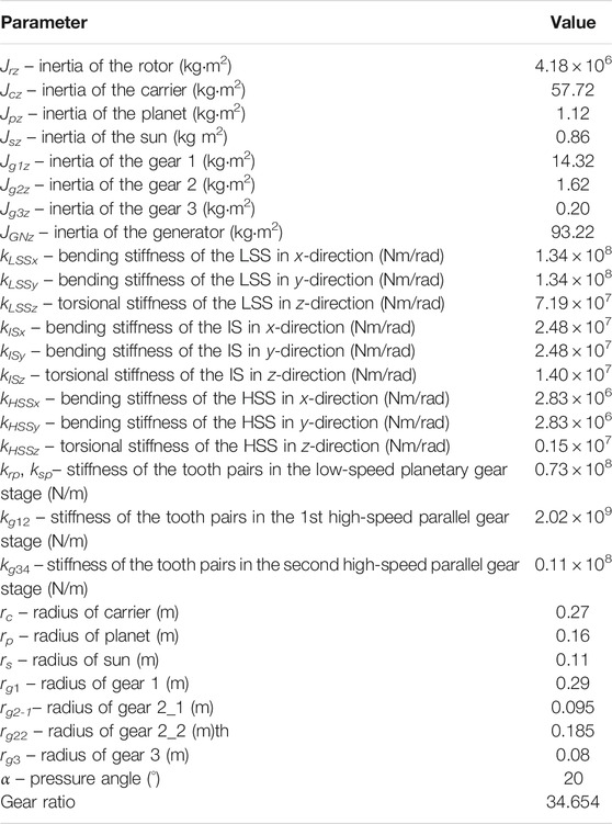
TABLE 2. Main properties of the drivetrain configuration.
Results and Discussion
Angular Displacement Comparison Between the Torsional Model and the Three-Dimensional Model
In previous torsional model, we assumed that each rotation occurred according to the shaft stiffness and the gear mesh which is represented by only rotational coordinates. However, rotation and translation are completely coupled by the bearing and the shaft in the 3D model. These behaviors affect each other. Hence, we can expect the coupled vibrations among the components.
Figure 6 presents the angular displacement difference between the torsional model and the 3D model. The angular displacement difference is presented for each component with respect to its rotational degree of freedom. It is oscillating according to the reference line. In Figure 6, there are periodic vibrations that have a zero-mean value. The magnitudes of vibration are increasing through the drivetrain due to the gear ratio. From this result, it is found that the vibrations of each component are similar trends with similar oscillating period and magnitude.
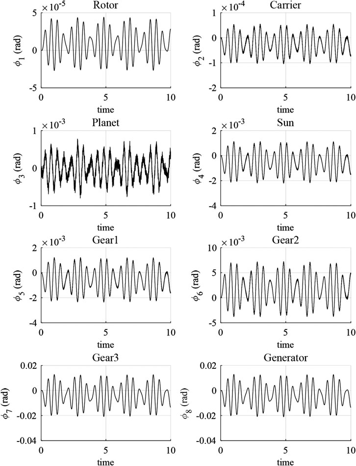
FIGURE 6. Angular displacement difference between the torsional model and the 3D model.
Contact Force Comparison Between the Torsional Model and the Three-Dimensional Model
The gear mesh is the most important part of the mechanical transmission system and it is also one of the most risky parts in the system. If an external force that is larger than the allowable force is applied to the system, the gear teeth will be adversely affected. In this chapter, the gear mesh contact force is compared between the torsional model and the 3D model.
Figure 7 plots the gear mesh contact force in the time domain. The results of two simulations demonstrate that the contact force has a constant period of approximately 0.4 s. The contact force is periodically presented due to the periodic gear mating. In the 3D model, irregular vibrations are observed around the periodic contact force. This phenomenon is caused by the backlash. In the torsional model, there is no factor that can cause the backlash except the angular displacement about the z-axis. Similar trend can be observed by comparing Figure 7 to Figures. 2, 3. However, the 3D model has five degrees of freedom. Each degree of freedom is not separated due to the shafts. Each shaft has a bending stiffness that can affect all five degrees of freedom, namely, the gear mesh will not contact and detach regularly.
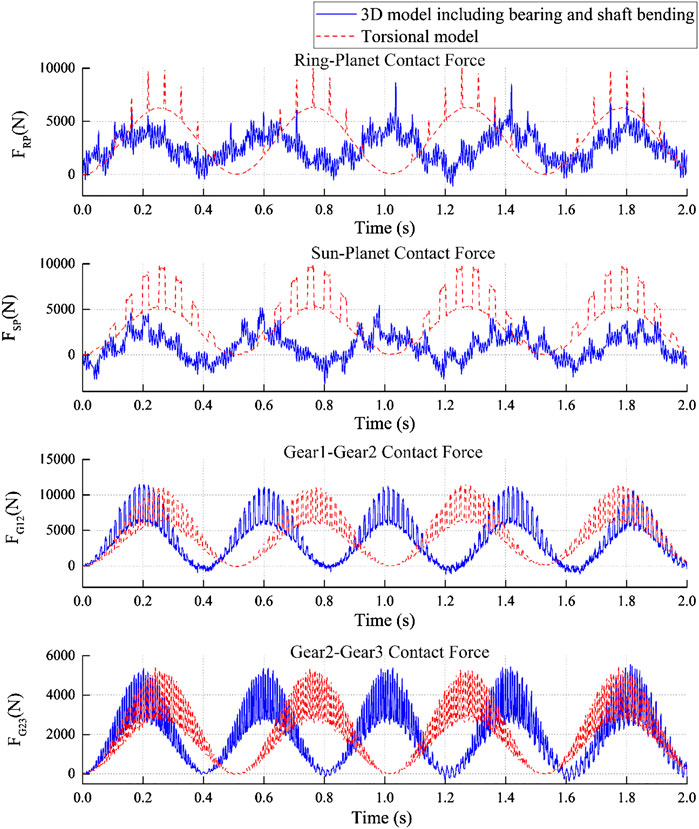
FIGURE 7. Gear mesh contact force comparison between the torsional model and the 3D model.
From the above results, the regular contact force results for the torsional model could be obtained. The zero minimum value of the contact force is identified for torsional model. Hence, two points on each gear are not affected when they are sufficiently fall away. However, this phenomenon is different for the 3D model. Due to the coupled motions of shaft bending and bearings, the vibration is not regular and occasionally attains the negative contact force. This is due to the occurrence of bearing and shaft bending, which cause the disturbances that include additional relations between the gear teeth when the gear teeth sufficiently separate away.
In each gear stage, a larger rotation between gear 1 and gear 2 is expected because they have the largest gear mesh stiffness and the largest gear radius ratio (Table 3). However, irregular vibrations occurred in the planetary gear stage more frequently compared to the parallel gear stage. Therefore, the shaft bending has significant effect on the dynamic response of planetary gear. In the planet gear stage, the sun gear and the planet gears are connected by a low-speed shaft and an intermediate shaft, and there are three planet gears. In contrast, there are only two gears in the parallel gear stage. Therefore, the planetary gear stage has higher risk, and its results agree with the gear mesh contact force results.
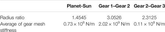
TABLE 3. Comparison of the gear radius ratio and the average gear mesh stiffness.
The gear mesh contact force in the frequency domain is presented in Figure 8. The gear mesh frequencies and its harmonic terms can be easily identified as dots mark in the plot. Frequencies of 18.30 Hz in the planetary gear stages, 63.06 Hz in gear 1–gear 2 stage, and 128.50 Hz in gear 2–gear 3 stage are dominant, and integer multiples up to n of each harmonic term are also represented. Gear 2-gear 3 has a higher gear mesh frequency due to its high angular velocity compared with other gear stage. Although the gear contacts of the ring-planet gear and planet-sun gear differ in terms of their mesh stiffness, the same gear mesh frequencies could be identified. Frequencies larger than 300 Hz may relate to the flexibility from bearing and shaft bending.
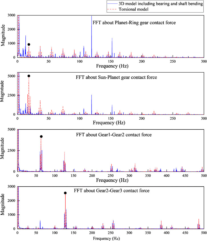
FIGURE 8. FFT of the gear mesh contact force.
In the 3D model, irregular peaks are observed, which are additional evidence of the coupled motion. Thus, it is necessary to include the shaft flexibility in the whole drivetrain model. Coupled relative motion can create additional vibration peaks; however, there is no large difference of the main characteristics of the system. Figure 9 shows a magnified view of the gear mesh frequency and the sideband peaks when the torsional model and 3D model are used. The location of the gear mesh frequency is the same and there is a shift for the sideband frequencies. The sideband distance is longer than that in the torsional model, namely, the system has a faster and longer rotating frequency signal compared to the torsional model. Therefore, if there is a strong shaft bending effect or eccentricity problem in the mass distribution, the gear mesh contact period becomes short and irregular small vibrations will occur.
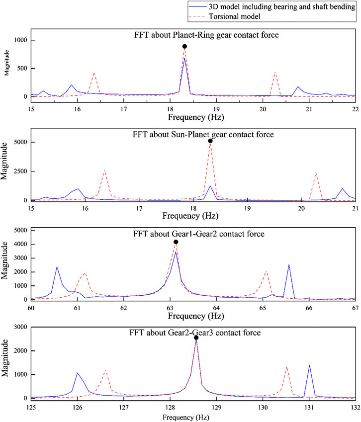
FIGURE 9. Comparison of the gear mesh frequency and the sideband frequencies.
In the drivetrain system, analysis in the frequency domain is used to identify the defects. Most problems are caused by the gear eccentricity, backlash, and bearing but not due to the gear wear. In these problems, the additional sideband peaks are identified around the gear mesh frequency, and the peak magnitudes will be also different.
Eccentricity Problem of Each Component
In the manufacturing process, not all the product could be made perfectly. For example, there are many production problems which include machine error, not well-mixed materials, and environmental conditions etc. Due to these problems, we may get unexpected rotation results that are caused by the eccentricity. In this chapter, the eccentricity of each component except the generator is considered among the simulations. From these results, we compared the rotational displacements between systems with and without the eccentricity. The eccentricity was defined as 20% of each component's radius, which is also considered in reference (Yassa et al., 2019). The planet gear causes the largest vibration due to the rotor eccentricity. Figure 10 presents the vibration results from seven simulations. The effect of the eccentricity is not significant. However, a general effect on the drivetrain system of the planet gear eccentricity is observed.
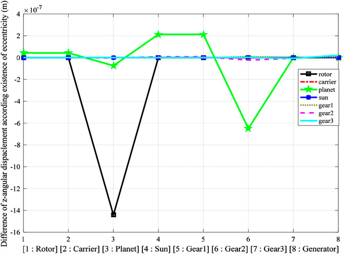
FIGURE 10. Eccentricity influence on the angular displacement of each component.
To identify its effects on the gear mesh contact force, it is better to characterize the gear mesh contact force that corresponds to each component's eccentricity. As the eccentricity of the rotor critically affects the dynamic responses of the drivetrain according to Figure 10, Figure 11 shows each gear mesh contact force with 20% eccentricity of the rotor. Even though the gear mesh contact force in the parallel gear stages, which include Gear 1 and Gear 2, shows a similar trend from the 3D model with 20% eccentricity of the rotor and from the 3D model without eccentricity, the planetary gear stages periodically exhibit irregular vibrations. The forces appear to be acceptable because the maximum value and the minimum value of the gear mesh force are not change significantly, which shows that the eccentricity problem cannot affect the relative gear mesh problem directly. However, there are many peaks in the high frequency region when the gear mesh frequency is investigated. This is the evidence of the shaft bending effect. The planetary stage is connected with a low-speed shaft that is long compared to the high speed shaft that is connected to the parallel gear stages. Hence, high bending stiffness with the eccentricity can induce irregular vibrations of the planetary stage.
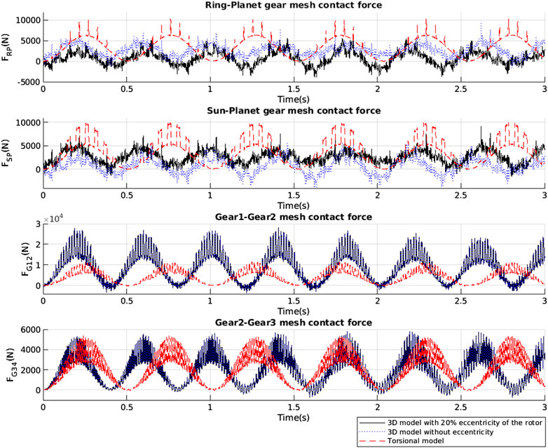
FIGURE 11. Eccentricity influence on the gear mesh contact force of each component.
Nacelle Movement
In this chapter, the nacelle movement effect on the dynamic response of the drivetrain system is investigated. Due to the acceleration of the nacelle, its movement is considered as the cause of the external force (6,250 N), which is obtained from the project in reference (Han et al., 2012). Figure 12 presents the gear mesh contact force with and without the nacelle movement. Similar trends could be identified for both contact forces with and without nacelle movement. The nacelle movement effect on the contact force is larger than the effect from the eccentricity and shaft bending. Therefore, the nacelle movement affects the gear mesh contact force directly.
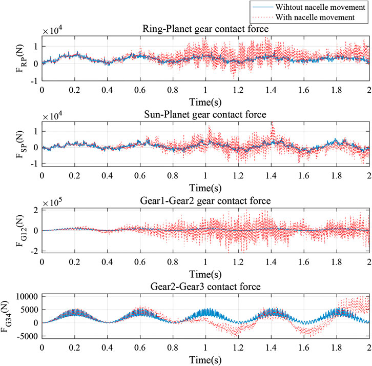
FIGURE 12. Gear mesh contact force in the nacelle movement simulation.
Conclusion
A 3D mathematical model of a wind turbine drivetrain was proposed in this study using multibody dynamics. The governing equation was derived using Lagrange's equation. The model took into account the flexibility of the gear mesh by using linear springs with time-varying stiffness, shaft bending, component eccentricity and nacelle movement. The shaft bending can affect the gear mesh contact force. As a result, irregular vibration occurs and the gear teeth are always subjected to loads even though two gear teeth detach away. Planetary gear stages are more sensitive to shaft bending and eccentricity than the parallel gear stages due to their complex geometry. As discussed in this study, in the wind turbine drivetrain system, the low-speed shaft and the intermediate shaft should be examined regularly. Additionally, the eccentricity in the mass distribution should be considered.
In addition, the effect of nacelle movement on the dynamic characteristics of the drivetrain was investigated. The nacelle movement can affect the gear mesh contact force directly. The results demonstrate that the gear teeth may damage due to rapid nacelle movement.
Further validation against experimental results will be carried out in the future work.
Data Availability Statement
The original contributions presented in the study are included in the article/Supplementary Material, further inquiries can be directed to the corresponding author.
Author Contributions
Conceptualization, YP, JY and WS; methodology, YP, JY and WS, CM; investigation, YP, HP, and ZM; writing—first draft preparation, YP and WS; writing, review and editing, HP. ZM, WS, and JY; visualization, YP; supervision, WS.
Funding
This work is supported by the National Natural Science Foundation of China (Grant No. 51709039, 52071058). This research was also partially funded by the New and Renewable Energy of the Korea Institute of Energy Technology Evaluation and Planning (KETEP) grant funded by the Korean Government Ministry of Knowledge and Economy (MKE), South Korea (No. 20113040020010) and the international collaboration and exchange program from the NSFC-RCUK/EPSRC with grant No. 51761135011.
Conflict of Interest
Author JY was employed by company Connect LNG.
The remaining authors declare that the research was conducted in the absence of any commercial or financial relationships that could be construed as a potential conflict of interest.
The reviewer CM declared a past co-authorship with one of the authors CM to the handling editor.
References
Bathe, K. J. (2006). Finite element procedures. Watertown, MA: Klaus-Jurgen BatheWatertown, 9780979004957.
Bhardwaj, U., Teixeira, A. P., and Soares, C. G. (2019). Reliability prediction of an offshore wind turbine gearbox. Renew. Energy 141, 693–706.
Craig, R. R., and Kurdila, A. J. (2006). Fundamentals of structural dynamics. New Jersey, NJ: John Wiley & Sons, 9780471430445.
Dong, W., Moan, T., and Gao, Z. (2014). “Gear contact fatigue reliability analysis for wind turbines under stochastic dynamic conditions considering inspection and repair,” in Proceedings of ASME 2014 33rd international conference on OceanOffshore and arctic engineering, Volume 4A Structures, Safety and Reliability, San Francisco, CA, June 8–13, 2014.
European Wind Energy Association (EWEA) (2020). Offshore wind in Europe key trends and statistics 2019. Brussels, Belgium: Wind Europe.
Han, J. H., Shi, W., Lee, D. Y., and Park, H. C. (2012). “Sensitivity study for environmental condition on offshore wind turbine jacket substructure,” in Proceedings of asia-pacific forum on renewable energy, Jeju, Korea, November 26–28, 2012.
He, X., Zhou, X., Xue, Z., Hou, Y., Liu, Q., and Wang, R. (2019). Effects of gear eccentricity on time-varying mesh stiffness and dynamic behavior of a two-stage gear system. J. Mech. Sci. Technol. 33 (3), 1019–1032.
Jiang, S., and Duan, S. S. (2011). “A four-rigid-body element model and computer simulation for flexible components of wind turbines,” in Proceedings of the ASME 2011 international mechanical engineering congress and exposition, Denver, CO, November 11–17, 2011.
Jiang, Z., Xing, Y., Guo, Y., Moan, T., and Gao, Z. (2015). Long‐term contact fatigue analysis of a planetary bearing in a land‐based wind turbine drivetrain. Wind Energy 18, 591–611.
Kim, H. W., and Yoo, W. S. (2007). “Selection of damping model in vibration of flexible beams,” in Proceedings of the Korean society of mechanical engineer conference, Busan, Korea. May 30–June 1, 2007.
Kim, Y., Kim, C. W., Lee, S., and Park, H. (2013). Dynamic modeling and numerical Analysis of a cold rolling mill. Int. J. Precis. Eng. Manuf. 14, 407–413.
Kumar, R., and Roy, S. K. (2020). “Dynamic analysis of wind turbine drivetrain under constant torque,” in Soft computing: theories and applications 2020. Singapore: Springer, 605–618.
Lee, D., Hodges, D. H., and Patil, M. J. (2002). Multi-flexible-body dynamic analysis of horizontal axis wind turbines. Wind Energy 5, 281–300.
Li, Z., Wen, B., Peng, Z., Dong, X., and Qu, Y. (2020). Dynamic modelling and analysis of wind turbine drivetrain considering the effects of non-torque loads. Appl. Math. Model.
Lin, J., and Parker, R. G. (2002). Planetary gear parametric instability caused by mesh stiffness variation. J. Sound Vib. 249 (1), 129–145.
Nejad, A. R., Gao, Z., and Moan, T. (2014). On long-term fatigue damage and reliability analysis of gears under wind loads in offshore wind turbine drivetrains. Int. J. Fatig 61, 116–128.
Nejad, A. R., Jiang, Z., Gao, Z., and Moan, T. (Oct 2016). “Drivetrain load effects in a 5-MW bottom-fixed wind turbine under blade-pitch fault condition and emergency shutdown,” in Proceedings of the Science of making torque from wind, Munich, Germany, October 5–7, 2016.
Shi, W., Kim, C. W., Chung, C. W., and Park, H. C. (2013). Dynamic modeling and analysis of a wind turbine drivetrain using the torsional dynamic model. Int. J. Precis. Eng. Manuf. 14, 153–159.
Shi, W., Park, Y., Park, H., and Ning, D. (2018). Dynamic analysis of the wind turbine drivetrain considering shaft bending effect. J. Mech. Sci. Technol. 32 (7), 3065–3072.
Shlecht, B., Shulze, T., and Rosenlocher, T. (Mar 2006). “Simulation of heavy drive trains with multimegawatt transmission power in SimPACK,” in Proceedings of SIMPACK users meeting, Baden-Baden, Germany, March 21–22, 2006.
Tan, J., Zhu, C., Song, C., Li, Y., and Xu, X. (2019). Dynamic modeling and analysis of wind turbine drivetrain considering platform motion. Mech. Mach. Theor. 140, 781–808.
Van der Linden, F. L. J., and de Souza Silva, P. V. (2009). “Modelling and simulating the efficiency and elasticity of gearboxes,” in Proceedings of the 7th international modelica conference, Como, Italy, September 20–22, 2009
Wang, J., Qin, D., and Ding, Y. (2009). Dynamic behavior of wind turbine by a mixed flexible-rigid multi-body model. J. Syst. Des. Dyn. 3, 403–419.
Wang, Z., Yin, Z., Wang, R., Cheng, Y., Allen, P., and Zhang, W. (2020). Coupled dynamic behaviour of a transmission system with gear eccentricities for a high-speed train. Veh. Syst. Dyn. 1, 1–22.
Xing, Y., and Moan, T. (2013). Multi-body modelling and analysis of a planet carrier in a wind turbine gearbox. Wind Energy 16, 1067–1089.
Yassa, N., Rachek, M., and Houassine, H. (2019). Motor current signature analysis for the air gap eccentricity detection in the squirrel cage induction machines. Energy Proc. 162, 251–262.
Keywords: wind turbine, drivetrain, structural analysis, shaft flexibility, eccentricity, variable gear mesh
Citation: Park Y, Park H, Ma Z, You J and Shi W (2021) Multibody Dynamic Analysis of a Wind Turbine Drivetrain in Consideration of the Shaft Bending Effect and a Variable Gear Mesh Including Eccentricity and Nacelle Movement. Front. Energy Res. 8:604414. doi: 10.3389/fenrg.2020.604414
Received: 09 September 2020; Accepted: 24 November 2020;
Published: 13 January 2021.
Edited by:
Yingyi Liu, Kyushu University, JapanReviewed by:
Puyang Zhang, Tianjin University, ChinaConstantine Michailides, Cyprus University of Technology, Cyprus
Copyright © 2021 Park, Park, Ma, You and Shi. This is an open-access article distributed under the terms of the Creative Commons Attribution License (CC BY). The use, distribution or reproduction in other forums is permitted, provided the original author(s) and the copyright owner(s) are credited and that the original publication in this journal is cited, in accordance with accepted academic practice. No use, distribution or reproduction is permitted which does not comply with these terms.
*Correspondence: Wei Shi, weishi@dlut.edu.cn