

Abstract
Future high energy physics colliders could benefit from accelerator magnets based on high-temperature superconductors, which may reach magnetic fields of up to 45 T at 4.2 K, twice the field limit of the two Nb-based superconductors. Bi2Sr2CaCu2O8-x (Bi-2212) is the only high-Tc cuprate material available as a twisted, multifilamentary and isotropic round wire. However, it has been hitherto unclear how an accelerator magnet can be fabricated from Bi-2212 round wires and whether high field quality can be achieved. This paper reports on the first demonstration of high current Bi-2212 coils using Rutherford cable based on a canted-cosine-theta (CCT) design and an overpressure processing heat treatment. Two Bi-2212 CCT coils, BIN5a and BIN5b, were made from a nine-strand Rutherford cable. Their electromagnetic design is identical, but they were fabricated differently: both coils underwent heat treatment in their aluminum–bronze mandrels, but unlike BIN5a that was impregnated with epoxy in its reaction mandrel, the conductor of BIN5b was transferred to a 3D printed Accura Bluestone mandrel after the heat treatment, a process attempted here for the first time, and was not impregnated. BIN5a reached a peak current of 4.1 kA with a self-field of 1.34 T in the bore. This corresponds to a wire engineering current density (Je) of 912 A mm−2, which is two times that of BIN2-IL, a previous Bi-2212 CCT coil fabricated at LBNL, which used a six-around-one cable processed with the conventional 1 bar pressure melt processing. On the other hand, BIN5b reached 3.1 kA. The coils exhibited no quench training. All the quenches were thermal runaways that occurred at the same location. In addition, we report on the field quality and ramp-dependent hysteresis measurements taken during the test of BIN5a at 4.2 K. Overall, our results demonstrate that the CCT technology is a route that should be further investigated for making high field, potentially quench training free dipole magnets with Bi-2212 cables.
Export citation and abstract BibTeX RIS
1. Introduction
Future 20 T class accelerator magnets may require high-temperature superconductors (HTS), which may reach magnetic fields of up to 45 T at 4.2 K [1]. This represents a technology leap. Among the HTS currently available in relatively long lengths for practical magnets, Bi2Sr2CaCu2O8−x (Bi-2212) is an isotropic, round, multifilamentary, powder in tube wire [1], and can be made into Rutherford cables [2] and wound into versatile magnet coil designs [3]. The Bi-2212 wire has exhibited a wire engineering current density (Je) of up to 950 A mm−2 at 30 T at 4.2 K, way beyond the current capabilities of Nb3Sn [4, 5].
One drawback of Bi-2212 is that its critical current (Ic) is strain sensitive. In the wire, the Bi-2212 filaments are embedded in a silver matrix, which is encased in an Ag-0.2 wt% Mg or Ag–Mg–Sb alloy outer sheath. Silver has high electrical and thermal conductivity [6], but its mechanical strength is insufficient for 20 T cosine-theta accelerator magnets. For this reason, Bi-2212 magnets must be designed in such a way to minimize the stress on the conductor caused by the Lorentz force during magnet operation, and the coils should be fabricated by the wind-and-react method to avoid handling the sensitive conductor after heat treatment.
The canted-cosine-theta (CCT) design provides stress management at the magnet design level. It allows us to intercept the Lorentz force at each single turn and transfer it to the mandrel structure, avoiding stress accumulation on the conductor [7–9]. The wind-and-react method, on the other hand, poses additional technical problems because the mandrel material must withstand the Bi-2212 heat treatment cycle that reaches a maximum temperature of 890 °C and pressures up to 50 bar in a flowing O2/Ar gas mixture environment [10]. The mandrel material must not experience significant oxidation, otherwise the oxygen partial pressure (pO2) in the furnace during heat treatment (usually, the selected pO2 = 1 bar) may not be sufficient to ensure the proper phase sequence and Bi-2212 melting temperature for achieving a high critical current density. Moreover, the mandrel must not exhibit significant deformation after heat treatment because the field quality would be affected. Finally, the mandrel material must retain its mechanical properties after heat treatment and serve as the structural support in order to prevent conductor damage due to the prestress applied when assembling the magnet, and due to stress produced by the Lorentz force during magnet operation.
One of the goals of the U.S. Magnet Development Program (US-MDP) is to fabricate a Bi-2212 CCT dipole magnet that produces a bore field of 5 T in standalone configuration, and then place it, as an insert coil, in the bore of a Nb3Sn dipole. The Bi-2212 CCT insert should increase by 3 T the field in the bore of the hybrid LTS/HTS dipole, assuming that the contribution of the Nb3Sn dipole is 15 T [11].
In the past, several Bi-2212 CCT coils were fabricated at LBNL using a Bi-2212 single wire and a six-around-one cable in the search for mandrel and insulation materials compatible with the Bi-2212 heat treatment process [12]. Among those coils, BIN2-IL was the only coil tested at 4.2 K [13]. A summary of the fabrication and testing of BIN2-IL is provided in section 2 of this paper.
In the framework of the US-MDP, two Bi-2212 CCT coils have been designed, fabricated and tested to demonstrate the application of Bi-2212 CCT technology in accelerator magnets, and to lay the foundations for producing a 5 T insert dipole. These coils are BIN5a and BIN5b. They both use a nine-strand Rutherford cable fabricated from a 0.8 mm diameter wire that carries 560 A at 5 T and 4.2 K. Their electromagnetic design is identical, but the fabrication process is different. The details about the geometric parameters of the coils, the electromagnetic design, mandrel and insulation materials and winding process, were reported in [14]. Several key fabrication improvements were identified with respect to the previous coils fabricated at LBNL, and were implemented in BIN5a and BIN5b. The most important improvement was to paint the Rutherford cable during the winding process with a TiO2 slurry, on top of the sleeve made of braided mullite fiber (2Al2O3·SiO2) that was already insulating the cable. This technique completely eliminated the electrical shorts encountered in previous prototypes that only used the mullite braided sleeve as insulation for the conductor [14].
Section 3 of this paper describes the remaining details of the fabrication process including heat treatment, instrumentation and impregnation, along with the challenges we faced during the process and the solutions we adopted. The most significant difference between the coils is that unlike BIN5a, the conductor of BIN5b was gently removed from its aluminum–bronze mandrel after heat treatment, and it was carefully rewound in a 3D printed Accura Bluestone epoxy-based mandrel. This applied some strain to the reacted conductor. In addition, BIN5a was impregnated to constrain the conductor movement in the channels during the test, and BIN5b was not.
The coils were individually tested first at 77 K to get as much information as possible about the transition current of each voltage tap section. Then each coil was tested at 4.2 K. Additionally, magnetic measurements were performed on the impregnated BIN5a coil during the test at 4.2 K to compare the coil's generated field with respect to the theoretical electromagnetic design. Sections 4 and 5 of this paper describe the results of the tests at 77 K and at 4.2 K, respectively.
2. Test of BIN2-IL at 4.2 K
BIN2-IL is the inner layer of BIN2, which is a two-layer Bi-2212 CCT magnet designed to study the fabrication challenges, particularly the compatibility of different mandrel materials with the Bi-2212 heat treatment. The design and fabrication of the coils were published in 2014 [12]. Only BIN2-IL was reacted and then tested at 4.2 K, although the test details were not published. BIN2-IL is a 20-turn coil that used a six-around-one cable made from 0.8 mm diameter Bi-2212 wires. The 2.4 mm diameter cable was insulated with mullite fiber sleeve, and wound in a mandrel made of aluminum–bronze 642 alloy. It underwent heat treatment with the conventional 1 bar melting processing in a horizontal tube furnace. After the heat treatment, the mandrel showed a pronounced axial distortion. However, the Bi-2212 leakage observed in BIN2-IL after the heat treatment was minimal compared to what was seen in BIN1, a two-layer CCT magnet that used Inconel-600 as mandrel material and a single Bi-2212 wire insulated with mullite braided sleeve [12].
At 4.2 K, the maximum current reached was about 1.47 kA, which corresponds to field on the conductor of 0.48 T. The magnetic dipole field was measured in the aperture using a rotating coil, and reached a maximum of 0.29 T.
3. Fabrication of BIN5a and BIN5b
BIN5a and BIN5b are two Bi-2212 CCT coils with the same design. Each winding consists of 13 turns (∼6.7 m long) of a nine-strand Rutherford cable fabricated at LBNL, cable No. 1093, with a nominal dimension of 4 mm × 1.44 mm. It is made from the wire PMM170725 (0.8 mm diameter, 55 × 18 architecture, untwisted). The wire was fabricated by Bruker OST LLC, using the precursor powder LXB-86 manufactured with a nanospray combustion technology by nGimat LLC (known as Engi-Mat LLC since 2019).
The Rutherford cable was insulated with a mullite fiber sleeve (wall thickness ∼150 µm). During the winding process, the insulated cable was additionally painted with a TiO2 slurry to eliminate the electrical shorts between the cable and the mandrel. The recipe and properties of the TiO2 slurry were published in [15, 16].
The mandrels are made of the aluminum–bronze 954 alloy. This material has proved to be compatible with Bi-2212 during the heat treatment due to the formation of Al2O3 on its surface, which prevents the underlying material from further oxidation [12]. Moreover, aluminum–bronze is easy to machine which makes it preferable for CCT mandrels with large aspect ratio channels, suitable to wind Rutherford cables [8, 17]. The mandrels have 63.5 mm outer diameter and are 390 mm long, designed to fit in the Deltech vertical overpressure processing furnace at the NHMFL, which has a homogeneous hot zone of 130 mm diameter and 450 mm height. The bore diameter of both coils is 51 mm, which is sufficiently large for inserting an anti-cryostat to take magnetic measurements during the test in liquid helium.
During the heat treatment, the cable anneals and adopts the shape of the longitudinally expanding mandrel, and during cooldown to room temperature, the mandrel contracts more than the cable and pushes on the cable in the pole regions, causing it to protrude out from the channels. The mandrels of BIN5a and BIN5b were machined with larger space in the pole regions to provide enough room for the mandrel to return to its original shape without pushing on the conductor. This technique was previously used on Nb3Sn CCT coils with satisfactory results [17]. It also improved the installation of voltage tap flags in the pole regions and the insertion of additional insulation around the voltage tap flags during the winding process [14].
In the following sections, the differences between the fabrication process of BIN5a and BIN5b are explained.
3.1. Fabrication of BIN5a
After winding, BIN5a was wrapped with a Nextel 610-DF-11 cloth to protect the winding, and an Inconel-600 wire mesh screen was placed around the assembly. The screen was secured with twisted Inconel-600 wires. No pre-oxidation cycle was carried out on the mandrel. The coil was heated up to 450 °C in flowing O2 to burn the organic materials in the mullite sleeve and the TiO2 slurry, and then it underwent a 50 bar overpressure processing at NHMFL.
Figure 1 shows the coil after the heat treatment. The dark spots on the conductor are signs of Bi-2212 liquid phase inside Bi-2212 filaments leaking through the silver matrix and sheath material during the heat treatment and reacting with the insulation. Bi-2212 leaks usually reduce the performance of the coils, and it is desirable to prevent them from appearing [18, 19].

Figure 1. BIN5a after heat treatment.
Download figure:
Standard image High-resolution imageThe mandrel was measured with a FARO CMM arm, showing minimal deformation [14], which represents a significant improvement with respect to the aluminum–bronze 642 mandrel of BIN2-IL. The splices were made with Nb-Ti Rutherford cables soldered to both sides of the reacted Bi-2212 cable. A total of 17 voltage taps were installed: one before and after each Nb-Ti splice and one per turn in the pole region (figure 2(a)). Finally, the coil was vacuum impregnated with the NHMFL Mix-61 epoxy.
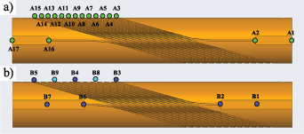
Figure 2. (a) Voltage tap map of BIN5a. (b) Voltage tap map of BIN5b; B1 to B6 were installed for the test at 77 K, and B8 and B9 were added afterwards for the test at 4.2 K.
Download figure:
Standard image High-resolution image3.2. Fabrication of BIN5b
Before winding, the aluminum–bronze 954 mandrel of BIN5b was pre-oxidized at 890 °C in a horizontal high temperature oxygen furnace at LBNL. After pre-oxidation, precision measurements were performed on the mandrel with a FARO CMM Arm, and we detected undesirable deformations in the azimuthal direction [14]. This happened because the mandrel was pre-oxidized in horizontal position without a mechanical structure to constrain the mandrel's diameter. The deformation towards the midplane was so severe that the aluminum–bronze 954 blocks used to keep the conductor straight in the precision-machined splice pocket during the heat treatment no longer fit, so new blocks were custom made to fit the warped pockets.
The coil was wound following the same procedure as BIN5a, and was wrapped with the same materials. In order to prevent further warpage during heat treatment, a previously pre-oxidized Inconel-600 strongback fixture was bolted around the assembled coil.
After removing the strongback and the wrapping materials, we found out that the custom-made blocks in the splice pockets had almost melted during heat treatment (figure 3). The visual inspection indicated that the blocks were not made of the specified aluminum–bronze 954, although a scanning electron microscopy and energy dispersive x-ray spectroscopy analysis of the specimen is pending to confirm this hypothesis.

Figure 3. BIN5b after heat treatment.
Download figure:
Standard image High-resolution imageThe viability of the coil was suspect and we would not know without testing it. However, it was certain that the melted material had contaminated and ruined the part of the reacted cable in contact with it in the splice region. The conductor was cut back away from the contaminated splice region, but there was not enough clean reacted conductor for the installation of the Nb-Ti splices.
At this juncture there were two options: (a) modify the aluminum–bronze 954 mandrel by lengthening the splice pocket with the conductor in place, or (b) remove the conductor from the mandrel and rewind it in another mandrel made of less expensive material, with a longer splice pocket specifically designed for the shorter conductor. Modifying the mandrel with the conductor in place would further damage the conductor and would introduce metal chips in the channels, causing electrical shorts. On the other hand, unwinding the coil would cause unpredictable strain and damage on the conductor, but would allow us to reuse the aluminum–bronze 954 mandrel in the future. Since it was uncertain whether the conductor was still viable, we decided to unwind the coil and save the mandrel. This technique was previously explored with Nb3Sn CCT coils at LBNL but the coils were never tested.
The conductor was transferred to a 3D printed Accura Bluestone epoxy-based mandrel. The process consisted of lifting the cable very carefully, and then placing G10 sheets between the cable and the mandrel to minimize rubbing on the metal mandrel when sliding the cable longitudinally towards the Accura Bluestone mandrel (figure 4). Similar to BIN5a, BIN5b showed dark spots on the conductor as a sign of Bi-2212 leaks during heat treatment (figure 3). During the unwinding process, we observed that the dark spots appear not only on the exposed edge of the conductor but also on the surfaces that are in contact with the mandrel, and do not follow a particular pattern. BIN5b was not impregnated. The idea behind this decision was to allow the cryogen to flow into the mandrel's channels. This would provide greater thermal stability to counteract the possible damage on the conductor caused by the unusual strain it experienced. Since the coil was not impregnated, only seven voltage taps were installed initially for a quick test in liquid nitrogen to verify if the coil becomes superconducting (figure 2(b)). The soldered splice installation was similar to that of BIN5a.

Figure 4. Process of transferring the conductor of BIN5b from the aluminum–bronze mandrel to the 3D printed Accura Bluestone mandrel. (a) Unwinding the BIN5b conductor from the aluminum–bronze mandrel. (b) Transferring the BIN5b conductor to the 3D printed mandrel. (c) The BIN5b conductor wound in the 3D printed mandrel.
Download figure:
Standard image High-resolution image4. Test of BIN5a and BIN5b at 77 K
Both coils were tested at 77 K at LBNL. The current was ramped up to 30 A for each coil separately. Figure 5 shows the voltage per unit length of each tap section of BIN5a and BIN5b. Tables 1 and 2 show the Ic and n-value of each tap section of BIN5a and BIN5b, respectively.

Figure 5. Transition from superconducting to normal conducting state of every tap section of BIN5a and BIN5b during their respective test at 77 K.
Download figure:
Standard image High-resolution imageTable 1. BIN5a test at 77 K. Parameters of the transition curve per tap section.
| Tap section | Ic (A) at 77 K a | n-value |
|---|---|---|
| A1–A2 (splice+) | 21.2 | 5 |
| A2–A3 | 18.0 | 5 |
| A3–A4 | 19.1 | 5 |
| A4–A5 | 18.3 | 5 |
| A5–A6 | 17.7 | 4 |
| A6–A7 | 17.7 | 5 |
| A7–A8 | 17.0 | 4 |
| A8–A9 | 17.9 | 4 |
| A9–A10 | 18.9 | 5 |
| A10–A11 | 18.6 | 5 |
| A11–A12 | 18.0 | 4 |
| A12–A13 | 17.6 | 4 |
| A13–A14 | 18.3 | 4 |
| A14–A15 | 18.6 | 5 |
| A15–A16 | 19.7 | 5 |
| A16–A17 (splice-) | 26.6 | 6 |
Table 2. BIN5b test at 77 K. Parameters of the transition curve per tap section.
| Tap section | Ic (A) at 77 K a | n-value |
|---|---|---|
| B1–B2 (splice+) | 12.1 | 4 |
| B2–B3 | 11.5 | 5 |
| B3–B4 | 18.4 | 4 |
| B4–B5 | 18.1 | 4 |
| B5–B6 | 13.1 | 4 |
| B6–B7 (splice-) | 17.1 | 4 |
BIN5b presented superconductivity despite the strain to which the conductor was subjected during the unwind/rewind process. Although some tap sections of BIN5b presented low Ic compared to BIN5a, other tap sections achieved Ic values similar to BIN5a.
This test provided feedback about the different sections of the coils. It served as a quality assurance method that helped us identify the sections of the coils with the lowest Ic, and decide that the coils were good to be tested at 4.2 K.
5. Test of BIN5a and BIN5b at 4.2 K
5.1. Test of BIN5a
Both coils were tested at 4.2 K at LBNL. BIN5a was tested first. A split aluminum cylindrical shell structure was installed over the coil. Before the aluminum structure was bolted on, the coil was wrapped with a Kapton sheet and a G10 sheet with a total thickness of 0.2 mm, to electrically isolate the coil.
During excitation, the quench event was detected by monitoring the voltage from the terminal voltage (tap section A1–A16) and triggering a signal to extract the energy from the coil when the voltage surpassed the threshold value (100 mV). The coil was protected by a dump resistor set at 20 mΩ.
During testing, the current of BIN5a was ramped up to quench six times at 30 A s−1, and then five times at ramp rates between 50 A s−1 and 200 A s−1. No training was observed in this coil. The term training refers to the increase of peak current observed in a magnet when it undergoes a series of tests where the current is ramped up until the magnet quenches. All the quenches occurred between 4011 A and 4127 A (figure 6). After 11 quenches, the coil did not show signs of damage.
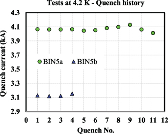
Figure 6. Quench history of BIN5a and BIN5b during their respective tests at 4.2 K.
Download figure:
Standard image High-resolution imageThe quenches occurred due to thermal runaways at the tap section A6–A7, which is located close to the middle of the coil (figure 2(a)). Figure 7(a) shows an example of the voltage increase in each tap section before the quench event. The tap section A6–A7 quenches first, but the section A7–A8 is the second with the highest voltage among all, which is located next to A6–A7. This behavior was observed in all the quench events. Table 3 shows the voltage and the Joule heating per unit volume of each tap section at 0.5 s before the thermal runaway. Note that the coil was intentionally driven to quench in order to test the quench characteristics. There was sufficient precursor resistive voltage (1 mV at 0.5 s before entering into thermal runaway) to predict and prevent quenches.
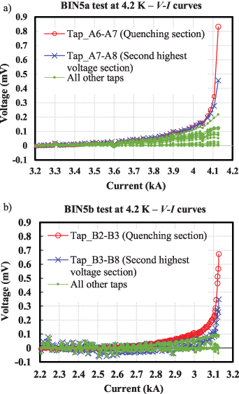
Figure 7. Example of voltage vs current in each tap section of each coil before the quench event. (a) BIN5a. (b) BIN5b.
Download figure:
Standard image High-resolution imageTable 3. BIN5a test at 4.2 K. Parameters of each tap section at 0.5 s before thermal runaway a .
| Tap section | Voltage (mV) | Joule heating density (kW m−3) |
|---|---|---|
| A1–A2 (splice+) | 1.1E-4 | 1.4 |
| A2–A3 | 0.01 | 26 |
| A3–A4 | 0.02 | 33 |
| A4–A5 | 0.06 | 84 |
| A5–A6 | 0.11 | 156 |
| A6–A7 | 0.15 | 208 |
| A7–A8 | 0.14 | 191 |
| A8–A9 | 0.08 | 106 |
| A9–A10 | 0.05 | 73 |
| A10–A11 | 0.06 | 77 |
| A11–A12 | 0.08 | 107 |
| A12–A13 | 0.09 | 122 |
| A13–A14 | 0.06 | 77 |
| A14–A15 | 0.04 | 60 |
| A15–A16 | 0.02 | 23 |
| A16–A17 (splice-) | 1.3E-4 | 1.8 |
a Transport current at 0.5 s before the thermal runaway is 4025 A.
Figure 8 shows the peak field along the conductor at the peak current, calculated using the Vector Fields Opera 18 finite element software. The position of the voltage taps is also represented. It can be seen that the tap section A6–A7, where all the quenches occurred, is not located at the high field region of the coil, and it does not present the highest field variation either. From the information about the field distribution in the coil, there is nothing that predicts that the thermal runaway would occur in section A6–A7.

Figure 8. Peak field calculated along the conductor at the peak current. The position of the voltage taps is indicated.
Download figure:
Standard image High-resolution imageThe peak current achieved by BIN5a corresponds to a wire Je of 912 A mm−2. This is twice as high as BIN2-IL (figure 9(a)).

Figure 9. (a) Loadline of BIN5a and peak current reached at 4.2 K. (b) Loadline of BIN5b and peak current reached at 4.2 K. The performance of BIN2-IL during its test at 4.2 K and the performance of the three witness samples that were placed at different heights inside the vertical furnace during the heat treatment of each coil are also represented.
Download figure:
Standard image High-resolution imageThe peak current reached by BIN5a is 64% of the short sample limit (SSL). The short sample is the PMM170725 wire with Ic = 560 A at 5 T. During the heat treatment process of BIN5a, three additional PMM170725 witness wires were placed at different heights inside the Deltech vertical furnace, and were tested afterwards. The critical surfaces of the short sample and the witness wires at 4.2 K are shown in figure 9(a). It can be noticed that the different witness wires performed differently, which evidences inhomogeneity in the heat treatment process. One of the witness samples reached only 390 A at 5 T. The peak current reached by BIN5a represents 85% of the performance of its worst witness sample.
The second part of the test consisted of taking magnetic field measurements in the bore of BIN5a from a rotating coil probe, which was inserted in an anti-cryostat that has 35 mm outer diameter. The rotating coil probe was developed by Fermilab based on the printed circuit board (PCB) technology [20]. The length of the PCB circuit is 26 mm. The outermost radius of the PCB trace is 11.75 mm which is also the reference radius for the reported field errors. The probe has ten layers of PCB coil circuits with two voltage signal outputs: an unbucked signal to determine the main field and a dipole-bucked signal to determine the high-order harmonics. The probe rotated at a frequency of 3 Hz during the field quality measurements. The output voltage signals were amplified with amplifiers and then digitized using a National Instruments digitizer (PXI-4472B). More details of the measurement system can be found in [21]. The data reduction followed the procedure described in [22].
First, the current was ramped up and held at 4 kA to measure the dipole field in the bore along the main axis of the coil. The maximum dipole field measured at 4 kA was 0.71 T, in the center region of the coil, which matches the prediction from the electromagnetic model. This corresponds to a maximum field in the conductor of 1.31 T (figure 10).
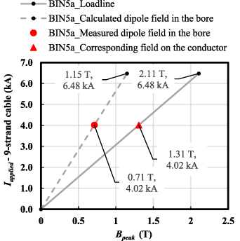
Figure 10. Peak field on the conductor and maximum dipole field in the bore vs current applied to the cable (from the electromagnetic model). Maximum dipole field in the bore of BIN5a at 4 kA, measured with the 26 mm long rotating coil, and the corresponding field on the conductor.
Download figure:
Standard image High-resolution imageAfterwards, the current was ramped up and held at 1 kA, where the Lorentz forces are negligible, to take field quality measurements. Figure 11 shows the transfer function of BIN5a. Figures 12–14 show examples of allowed and non-allowed higher order multipoles along the main axis of the coil, at the reference radius 11.75 mm.
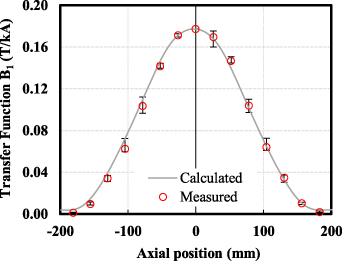
Figure 11. Transfer function of BIN5a at 1 kA, measured with the 26 mm long rotating coil.
Download figure:
Standard image High-resolution image
Figure 12. Sextupole component along the main axis of BIN5a at 1 kA, at the reference radius 11.75 mm, measured with the 26 mm long rotating coil.
Download figure:
Standard image High-resolution image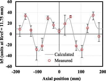
Figure 13. Decapole component along the main axis of BIN5a at 1 kA, at the reference radius 11.75 mm, measured with the 26 mm long rotating coil.
Download figure:
Standard image High-resolution image
Figure 14. Skew quadrupole component along the main axis of BIN5a at 1 kA, at the reference radius 11.75 mm, measured with the 26 mm long rotating coil.
Download figure:
Standard image High-resolution imageFinally, the rotating coil probe was positioned at the center region of the coil, where the dipole field reaches its maximum value. The current was ramped up to 3.8 kA and then ramped down. The ramp rate was 10 A s−1. Figures 15–17 show the behavior of the transfer function, the normal sextupole component (b3) and the normal decapole component (b5), respectively, during the ramps.
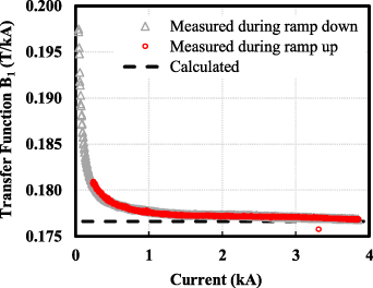
Figure 15. The dipole transfer function as a function of the current, measured at the center region of the coil with the 26 mm long rotating coil, and compared with the geometric value.
Download figure:
Standard image High-resolution image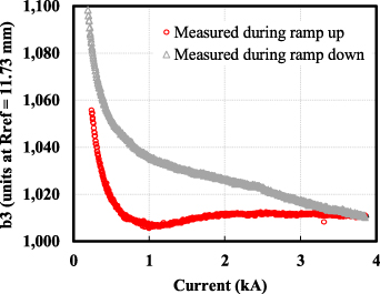
Figure 16. Sextupole component as a function of the current, measured at the center region of the coil with the 26 mm long rotating coil.
Download figure:
Standard image High-resolution image
Figure 17. Decapole component as a function of the current, measured at the center region of the coil with the 26 mm long rotating coil.
Download figure:
Standard image High-resolution image
5.2. Test of BIN5b
The test of BIN5b at 4.2 K followed the same procedure as the test of BIN5a, except magnetic field measurements were not carried out. Because both coils had the same electromagnetic design, we assumed they would generate the same dipole field. For this test, two additional voltage taps were installed in BIN5b (figure 2(b)) to gather more voltage data. Since the coil was not impregnated, all the voltage taps were bonded with Stycast.
The current of BIN5b was ramped up to quench four times at different ramp rates between 30 A s−1 and 100 A s−1. No training was observed. All the quenches occurred between 3118 A and 3128 A (figure 6).
The quenches occurred due to thermal runaways at the tap section B2–B3. Figure 7(b) shows an example of the voltage increase in each tap section before the quench event. Similar to what happened during the BIN5a test, the tap section B2–B3 quenches first, but the section B3–B8 is the second with the highest voltage among all, which is located next to B2–B3. This behavior was observed in all the quench events. Table 4 shows the voltage and the Joule heating per unit length of each tap section at 0.5 s before the thermal runaway.
Table 4. BIN5b test at 4.2 K. Parameters of each tap section at 0.5 s before thermal runaway a .
| Tap section | Voltage (mV) | Joule heating density (kW m−3) |
|---|---|---|
| B1–B2 (splice+) | 1.4E-4 | 1.5 |
| B2–B3 | 0.24 | 822 |
| B3–B8 | 0.14 | 50 |
| B8–B4 | 0.02 | 7.5 |
| B4–B9 | 0.02 | 7.9 |
| B9–B5 | 0.02 | 8.2 |
| B5–B6 | 0.02 | 24 |
| B6–B7 (splice-) | 1.9E-4 | 2.0 |
a Transport current at 0.5 s before the thermal runaway is 3110 A.
The peak current achieved by BIN5b corresponds to a Je of 700 A mm−2, which is lower than that of BIN5a, but it is still higher than that of BIN2-IL [12].
BIN5b reached 48% of the SSL (figure 9(b)). The short sample is the same as for BIN5a. During the heat treatment process of BIN5b, three PMM170725 witness wires were placed at different heights inside the Deltech vertical furnace, and were tested afterwards. The critical surface at 4.2 K corresponding to the short sample and to each witness wire is shown in figure 9(b). The three witness wires performed worse than the short sample. This shows that the quality of the heat treatment process of BIN5b is lower than that of BIN5a. The peak current of BIN5b represents 75% of the performance of its worst witness wire.
6. Discussion
BIN5a and BIN5b are the first Bi-2212 CCT coils made from Rutherford cable to have reached high current and high Je. However, the performance of the coils with respect to the SSL was lower than expected. We expected to reach close to 80% of SSL based on the results of Bi-2212 racetrack coils tested at LBNL [19].
The first factor causing the low performance could be the Bi-2212 leaks observed in both coils. In [19], it was shown that reducing these leaks allows the achievement of higher critical currents. The authors almost eliminated the leakage in racetrack coils by painting the Bi-2212 Rutherford cable with TiO2 slurry before putting the mullite sleeve insulation on the cable. In future CCT coils, we will implement the solution adopted in [19] to avoid Bi-2212 leaks. Nevertheless, the leaks do not explain why the thermal runaways always occurred at the same tap section in our CCT coils since the leaks appeared everywhere in the cable without a defined pattern.
Another important factor influencing the performance of the coils is the temperature control during the heat treatment. The wire taken as reference for the SSL was not heat treated together with the coils, thus it did not experience the same environmental conditions with the added thermal mass in the system that the coils represent. The performance of the witness samples placed at different heights of the furnace during the coils' heat treatment indicated inhomogeneities in the process. This shows the need for better temperature feedback from the furnace during the heat treatment.
In general, the heat treatment of BIN5b was worse than that of BIN5a, likely because of the presence of the strongback and the larger thermal mass. However, BIN5b reached only 75% of the performance of its worst witness wire, whereas BIN5a reached 85% of the performance of its worst witness wire. This is an indication that additional factors affected the performance of BIN5b beyond the heat treatment quality.
The main differences between the fabrication process of BIN5a and BIN5b are the removal of the BIN5b conductor from its original mandrel after heat treatment, and the nonimpregnation of BIN5b. Handling the Bi-2212 conductor after heat treatment, when it is strain sensitive, is probably the additional factor that affected the performance of BIN5b since it was an uncontrolled process. However, it is difficult to assess whether this factor had more impact on the low performance of BIN5b than the poor quality of the heat treatment.
The performance of BIN5a and BIN5b was not driven by the magnetic field distribution in the coils. In the case of BIN5a, the quenching section (A6–A7) and the section with the second highest voltage before the quench (A7–A8), were not located in the high field region of the coil. When we observe the parameters of the transition curves of the tap sections of BIN5a during the test at 77 K (table 1 and figure 5), we notice that A7–A8 has the lowest Ic. However, except for the splices, the Ic of other sections do not differ practically from the Ic of A7–A8. Before the thermal runaway, the voltage and the Joule heating in A6–A7 and A7–A8 are similar, and are higher than in the other sections (table 3). For this reason, we suppose that the thermal runaways occurred mainly due to inhomogeneities in the Bi-2212 formation in the region where the taps A6–A7 and A7–A8 are located, which became impactful at higher current. This would indicate that the performance of BIN5a was mainly driven by the quality of the heat treatment.
In the case of BIN5b, the quenching section (B2–B3) and the section with the second highest voltage before the quench (B3–B8) are located in the high field region of the coil (figure 8). However, the section B5–B6 is also located in the high field region and its voltage is much lower. Moreover, during the test at 77 K, where the magnetic field is very low to have an impact on the performance, B2–B3 was also the section with the lowest Ic. Before the thermal runaway, B2–B3 experienced much higher voltage and much higher Joule heating than any other section. For this reason, we strongly believe that the thermal runaway occurred due to a localized damage very close to the tap B3, which also caused the propagation of heat and voltage increase in the section B3–B8, which is next to the tap B3. Since the damage is so obvious from the data and is localized in the pole region, it was probably a consequence of abrupt strain during the unwinding process. Nevertheless, BIN5b performed better than BIN2-IL. We did not expect such a good performance since it is the first test done to a CCT superconductor coil to which such an unconventional process had been applied.
Another important achievement of this work is that field harmonics and persistent current effects were measured for the first time in a Bi-2212 CCT coil. The field harmonics calculated from the electromagnetic model, assuming a perfectly positioned conductor, and the field harmonics obtained from the measurements, agree reasonably well. Since BIN5a was impregnated, the discrepancy between the calculations and the measurements in the multipole components was caused by the conductor displacement during heat treatment.
The persistent-current effect caused large deviation from the geometric value at low currents and hysteresis between the ramp branches. However, the persistent-current effect observed in BIN5a is smaller than that observed in the C1, a two-layer CCT magnet wound with a CORC® wire [23]. The smaller element size in the Bi-2212 conductor might contribute to this behavior.
7. Conclusion
For the first time, we demonstrated that high current can be achieved in Bi-2212 CCT coils made from Rutherford cables, and described the manufacturing experience and experimental data of its quench performance and field quality. We conclude that the CCT technology is worth developing to make high field dipole magnets with Bi-2212 cables.
Two Bi-2212 CCT coils, BIN5a and BIN5b, made from the same nine-strand Rutherford cable, were successfully fabricated and tested at 77 K and at 4.2 K. BIN5a reached a Je of 912 A mm−2, and BIN5b reached 700 A mm−2, much higher than BIN2-IL, a previous Bi-2212 CCT coil tested at LBNL, which reached 420 A mm−2.
BIN5b reached lower performance than BIN5a, probably due to unwinding the coil after reaction and transferring the conductor to another mandrel. However, this experiment opens the possibility of exploring new fabrication approaches using different mandrel materials for the heat treatment and the test.
The two main factors identified as limiting the performance of the coils were the Bi-2212 leaks and the inhomogeneities in the heat treatment process. The leaks can be controlled by adding a layer of TiO2 on the bare Rutherford cable. For improving the quality of the heat treatment, better modeling and experimental temperature feedback systems are needed.
The coils did not train during the test at 4.2 K, and the terminal voltage before the thermal runaways was high enough to be detected in a noisy voltage environment. It means that a high field Bi-2212 CCT magnet does not have to be ramped up to quench during testing. This would substantially reduce the cost of the test.
Our work thus provided the first demonstration that high-field accelerator magnets can be made from Bi-2212 wires using the CCT design.
8. Future plans
We aim to continue demonstrating high current in Bi-2212 CCT coils. The next step is to fabricate Bi-2212 CCT subscale dipole magnets as an R&D vehicle to explore technology variants. Currently, there is a two-layer subscale dipole magnet under fabrication: BIN5c. Its outer layer is similar to BIN5a and BIN5b, and it is intended to continue improving the technology for Bi-2212 CCT fabrication and test. The cable of BIN5c has been painted with TiO2 directly on the silver to minimize the Bi-2212 leaks during heat treatment. The BIN5c coils will also be tested in the background field provided by CCT5: a 90 mm bore Nb3Sn CCT magnet that produces 8 T, fabricated at LBNL (publication in progress), to experimentally explore the hybrid Nb3Sn/Bi-2212 magnet technology. This experiment will examine whether Bi-2212 CCT coils remain as quench training-free at 8–10 T.
A more challenging plan in the mid-term is the fabrication of a 0.8 m long Bi-2212 CCT magnet demo to generate 5 T in a 50 mm diameter bore. Its outer diameter is 100 mm, to potentially fit into an outsert with a 120 mm aperture. It would produce 3.5 T in a background field of 15 T. The conductor will be a 17-strand Bi-2212 Rutherford cable. The coils will undergo overpressure processing heat treatment in a new vertical furnace called RENEGADE, to be commissioned in 2020 at the NHMFL. RENEGADE will have a homogeneous hot zone of 25 cm diameter and 100 cm height.
Acknowledgments
The work at LBNL is supported by the Director, Office of Science of the U S Department of Energy (DOE) under Contract No. DE-AC02-05CH11231. The authors thank Andy Lin, Hugh Higley, Matt Reynolds, James Swanson Timothy Bogdanof, Jordan Taylor and Marcos Turqueti for their assistance with coil fabrication and tests. We are grateful to nGimat LLC, known as Engi-Mat Co. since 2019, and Bruker OST LLC, which was supported by the U S Department of Energy through an SBIR grant, for donating the Bi-2212 strand. Thanks to our collaborators within the U S Magnet Development Program at the NHMFL, including: Dr Jianyi Jiang for characterizing the strand, Dr Jun Lu for providing the TiO2 slurry and Emma Martin for processing the heat treatment data. Cory Myers thanks the U S DOE Office of Science Graduate Student Research (SCGSR) for a student scholarship.