Article

Experimental Study on Heating Performances of Integrated Battery and HVAC System with Serial and Parallel Circuits for Electric Vehicle

1
Thermal Management R&D Center, KATECH, 303 Pungse-ro, Pungse-Myun, Cheonan 31214, Korea
2
Department of Mechanical Engineering, Dong-A University, 37 Nakdong-Daero 550, Saha-gu, Busan 49315, Korea
3
Department of Robotics and Intelligent Machine, Yeungnam University, 280 Daehak-Ro, Gyeongsan, Gyeongbuk 38541, Korea
*
Authors to whom correspondence should be addressed.
These authors contributed equally to this work.
Symmetry 2021, 13(1), 93; https://doi.org/10.3390/sym13010093
Submission received: 4 December 2020 / Revised: 1 January 2021 / Accepted: 4 January 2021 / Published: 7 January 2021
(This article belongs to the Special Issue Heat Transfer in Engineering)

Abstract

:
The objective of the present study is to conduct experiments for investigating heating performances of integrated system with serial and parallel circuits for battery and heating ventilation and air conditioning system (HVAC) of electric vehicles under various operating conditions. In addition, the artificial neural network (ANN) model is proposed to accurately predict the heating performances of integrated system with serial and parallel circuits for battery and HVAC. A test bench of integrated system with serial and parallel circuits has been developed for establishing the trade-off between battery heating and HVAC heating. The heating performances namely, battery out temperature, battery temperature rise rate, battery heating capacity, HVAC heating capacity and total heating capacity are evaluated experimentally for the integrated system with serial and parallel circuits. The behavior of various heating performances is evaluated under influence of flow rate and heater power. Battery out temperature reaches 40 °C within 10 min with rise rate of 2.17 °C/min for the integrated system with serial circuit and that within 20 min with rise rate of 1.22 °C/min for the integrated system with parallel circuit. Integrated system with serial circuit shows higher HVAC heating capacity than integrated system with parallel circuit which are 5726.33 W and 3869.15 W, respectively. ANN model with back-propagation algorithm, Levenberg-Marquardt training variant, Tan-sigmoidal transfer function and 20 hidden neurons presents the accurate prediction of heating performances of the integrated system with serial and parallel circuits for battery and HVAC.

1. Introduction

In recent times, increasing demand of high energy efficiency and zero emission has resulted into shifting the major means of transportation towards the electric vehicle [1]. The low driving range and battery life are two major hurdles in the development of electric vehicles. The cabin is heated in winter using electric energy of the battery, which results into reduction in driving range of vehicle [2]. The charge-discharge performances of the batteries are degrading significantly as the temperature reduces. In cold weather conditions, to maintain the battery performance and battery life, effective battery thermal management in form of preheating of battery is essential [3]. Numerous studies have been conducted focusing on cabin heating and battery heating in cold weather conditions to improve the driving range and battery performance.
Guo et al. presented effective heating for battery cell and battery pack using echelon internal heating strategy [4]. Ruan et al. developed an optimal internal heating strategy for rapid battery heating [5]. Lei et al. suggested an intermittent self-heating lithium-ion battery method for heating of battery with temperature uniformity [6]. Shang et al. proposed buck-boost conversion based high frequency alternating current heater for battery heating in low temperature conditions. As the AC heating frequency increases, the heating speed and efficiency improve, due to lithium-ion transport and increase in heat generation of ohmic resistance [7]. Fan et al. concluded that the discharge rate has negligible effect on the heating performance of battery thermal management system compare with external heating source. In addition, a higher mass flow rate of the heating medium gives better heating performance [8]. Delos Reyes et al. investigated the behavior in driving ranges of Mitsubishi i-MiEV and Nissan Leaf for the ambient temperature variation in a range of 20 to −15 °C [9].
Positive temperature coefficient (PTC) heaters are widely used for cabin heating, however, they consume more energy. Therefore, heat pumps have been used as the replacement of PTC heater for cabin heating [10]. Zhang et al. showed coefficient of performance (COP) of 1.25 and improvement of 57.7% in heating capacity using economized vapor injection heat pump system [11]. Cho et al. proposed a coolant source heat pump which uses waste heat from electric devices for heating a passengers’ compartment of electric bus [12]. Qin et al. presented that the air source heat pump with refrigerant injection shows enhancement in the heating capacity compared with the conventional air source heat pump for electric vehicles [13,14,15]. Ahn et al. investigated heating performances of air source heat pump, waste heat pump and dual source (air + waste heat) heat pump for electric vehicle, and concluded that the dual source heat pump shows superior heating performances compared with air source and waste heat pumps [16]. Lee et al. proposed an R744 based stack coolant heat pump, which attains a heating capacity of 5.0 kW at an ambient temperature of −20 °C [17]. Shi et al. suggested R32 based economized vapor injection heat pump system for temperature range of −2 to 15 °C, and showed higher coefficient of performance compare with conventional single stage heat pump [18]. Jung et al. showed that the single injection heat pump with optimum port angle of 440° and dual injection heat pump with optimum port angles of 535°/355° present enhancement of 7.5% and 9.8%, respectively, in coefficient of performance, compared with non-injection heat pump at ambient temperature of −10 °C [19]. Patil et al. proposed a 2.0 kW burner that shows a maximum efficiency of 96.7% for the cabin heating of an electric vehicle [20]. Zhang et al. showed that the heat pump system with desiccant reduces cabin heat load and power consumption by 42% and 38%, respectively, at an ambient temperature of −20 °C, compared to traditional heat pump system [21]. Choi et al. investigated the heating performances of vapor injection heat pump system for cabin heating of electric vehicle in cold weather conditions [22,23]. Ahn et al. showed that the dual evaporator heat pump has 62% higher heating coefficient of performance for cabin in electric vehicle compare with conventional heat pump [24]. Lee et al. proposed a mobile heat pump which uses waste heat of electric devices for heating in an electric bus. The heating coefficient of performance of proposed heat pump is evaluated as 2.4 [25]. Liu et al. investigated heating performances of propane-based heat pump system for cabin heating in electric vehicles and found that the proposed system shows superior heating performance above the ambient temperature of −10 °C [26]. Li et al. compared heating performances of an R134a based heat pump and an R1234yf based heat pump, and showed that the R1234yf based heat pump is a potential candidate for the replacement of the R134a based heat pump for cabin heating in cold weather conditions [27]. Bellocchi et al. developed a heat pump with a regenerative heat exchanger, which reduces power consumption by 17–52% and reduces the decrease in driving range up to 6% for electric vehicles [28]. Lee et al. proposed air source heat pump system with a heating coefficient of 3.26 and a heating capacity of 3.10 kW at an ambient temperature of −10 °C for cabin heating in electric vehicle [29]. Lee et al. have experimentally investigated the performance characteristics of heat pump system integrated with a high pressure side chiller under cold and hot weather conditions for light duty commercial electric vehicles [30]. Jeffs et al. integrated five different heat sources with heat pump system for efficient heating of battery and cabin. An energy saving of 14.8% was achieved with a heat pump system integrated with different heat sources [31]. Further, Jeff et al. proposed an optimal strategy for tradeoff heating between battery and cabin. The optimal strategy enables 6.2% of improvement in range for no battery heating and 5.5% of improvement in cabin comfort for full battery heating [32].
From the literature review, there are very few studies that discuss combined cabin and battery heating. Therefore, the objective of the present study is to develop an integrated system with serial and parallel circuits to enable the trade-off between battery heating and heating ventilation and air conditioning system (HVAC) (cabin) heating. The battery and HVAC heating performances, namely, battery out temperature, battery temperature rise rate, battery heating capacity, HVAC (cabin) heating capacity and total heating capacity, are compared experimentally for the integrated system with serial and parallel circuits under the influence of heater power and flow rate. In addition, an ANN model is developed in the present study, to accurately predict the battery and HVAC heating performances.

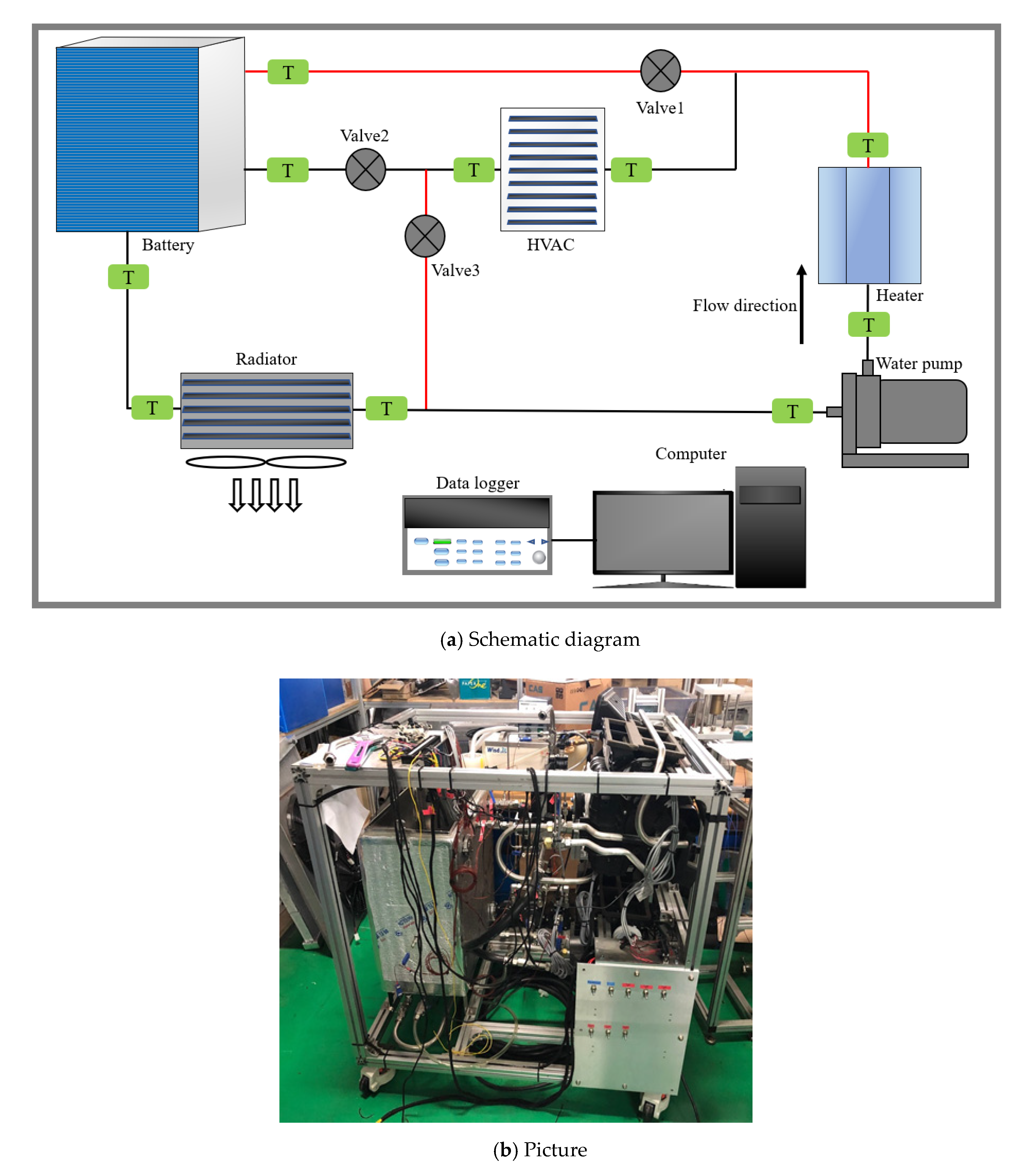
2. Experimental Method

The experimental set-up of the integrated system with serial and parallel circuits is shown in Figure 1. To control the experimental ambient conditions, the experimental set-up is housed inside the psychrometric calorimeter which is controlled using PID controller. The experimental set-up comprises of serial and parallel circuits with components namely, battery, HVAC heater core, heater, water pump, working fluid tank, radiator, temperature sensors, flow meters and valves. The specifications of various components of experimental set-up are presented in Table 1. Both the circuits are operated using three valves, named valve1, valve2 and valve3. For the integrated system with serial circuit, valve1 and valve3 are cutoff and only valve2 is operated. Whereas, for the integrated system with parallel circuit, valve2 is cutoff and valve1 and valve3 are operated. The valve1 supplies working fluid for the battery heating and valve3 supplies working fluid for HVAC heating in the integrated system with parallel circuit. The battery is not the actual battery but the mimic of GM Volt (2010) battery model whose specifications are: weight = 198 kg, specific heat = 143 J/kg K and battery capacity = 16 kWh. The total working fluid flow rate of 24 L/min is divided for battery heating and HVAC heating in the integrated system with parallel circuit using valve1 and valve3. For the integrated system with parallel circuit, the flow ratio term is defined which is the ratio of battery flow rate to HVAC flow rate. In the case of an integrated system with serial circuit, full working fluid flow rate of 24 L/min is either supplied for battery heating or HVAC heating using valve2. The working of the integrated system with serial and parallel circuits involves a supply of working fluid using water pumped to a heater, where it is heated to higher temperature. From the heater, the heated working fluid is divided between the battery and HVAC in the case of an integrated system with a parallel circuit, and totally supplied for either the battery or HVAC in the case of an integrated system with serial circuit. The collected heated working fluid in tank is transferred through the radiator where it is cooled and again transferred to the heater using a water pump. To analyze the heating performances of the battery and HVAC, two modes (serial and parallel) of operation are employed. In addition, the heater power is varied as 2 kW, 4 kW and 6 kW in both the modes, and the flow ratio is varied as 2/8, 3/7, 5/5, 7/3 and 8/2 in a parallel mode of operation, to investigate the behavior of battery and HVAC heating performances. Battery out temperature, battery temperature rise rate, battery heating capacity, HVAC heating capacity and total heating capacity are investigated under various operating conditions. The accuracy of various experimental devices and instruments is shown in Table 2. Additionally, Figure 1b shows the picture of an experimental set-up of the integrated system with serial and parallel circuits.
The poor calibration, instrumental errors, positional errors of probes, environmental error etc., are responsible for the uncertainty in the experimental results [33]. Therefore, the uncertainty analysis is conducted on the experimental results of the integrated system with serial and parallel circuits, to ensure the accuracy and reliability of the experimental test results [34]. The errors in experimental data of temperature and flow rate measurements cause uncertainties in the heating performances of battery and HVAC of the integrated system with serial and parallel circuits. The uncertainties in the output parameter due to uncertainties in the input parameters are calculated using Equation (1) [35]. The uncertainties in various parameters for the experimental study on integrated system with serial and parallel circuits could be calculated using the concept of linear fraction approximation [36].
U F = [ ( F X 1 U 1 ) 2 + ( F X 2 U 2 ) 2 + + ( F X n U n ) 2 ] 1 2
Here, X 1 , X 2 , …   X n are the input parameters, U 1 , U 2 , … U n are the uncertainties in the input parameters, F is the output parameter and U F is the uncertainty in the output parameter. Using Equation (1), the uncertainties in flow rate, battery out temperature and HVAC heating capacity are calculated as 1.50%, 0.75% and 1.68%, respectively.

3. Artificial Neural Network (ANN)

In recent times, ANNs are used for the performance prediction, forecasting, modeling, simulation and optimization of various physical systems. The working principle of ANN is based on a biological neural network [37]. When the input and output parameters with a larger data set is interrelated in a nonlinear relationship with each other, in those cases the ANN is the efficient tool to relate these parameters with less complexity than the conventional mathematical techniques [38]. The structure of the ANN model includes three layers namely, an input layer, a hidden layer and an output layer [39]. Each layer comprises a suitable number of neurons: the number of neurons in the input layer is equal to the number of input parameters, the number of neurons in the output layer is equal to the number output parameters and the number of neurons in the hidden layer is adjusted based on the training error [40]. Neurons in one layer are connected with the other layer’s neurons using weights and two neurons are connected by a single weight value [41]. The structure of the ANN model including layers, neurons and weights is trained using a training algorithm. The construction of training algorithm includes training variant and transfer function [39]. The maximum training error and maximum number of epochs are set as stopping criteria for training. The structure of the ANN model is trained using the selected training algorithm until the desired output or permissible error is obtained [42]. In the training process, the weights assigned between neurons are adjusted to achieve the desired output. If the desired output or the permissible errors is not achieved, then the different combination of training algorithm, training variant, transfer function, number of hidden layers and hidden neurons is used for further training. The trained ANN model that shows a higher prediction accuracy, with a predicted output closer to the actual results, is suggested as the optimum ANN model.
In the present study, an ANN model with various algorithms is developed for the prediction of battery and HVAC heating performances of the integrated system with a serial circuit and with a parallel circuit. The formulated structure of an ANN model for the integrated system with serial and parallel circuits is presented in Figure 2. The aim of the development of ANN models is to predict the battery and HVAC heating performances, which are indicated by battery out temperature and HVAC temperature difference. The battery out temperature and HVAC temperature difference are most affected by heater power and flow rate, which vary in real time. Therefore, the ANN model for the integrated system with serial and parallel circuits is formulated to predict the battery out temperature and HVAC temperature difference as the output parameters, for various conditions of heater power, flow rate and time as the input parameters. The training algorithm comprises of back-propagation algorithm, Levenberg-Marquardt (LM) training variant, Tan-Sigmoidal (Tan) and Log-Sigmoidal (Log) transfer functions, one hidden layer and 10, 15 and 20 number of hidden neurons [38]. The maximum training error and maximum number of epochs are set to 10−6 and 1000, respectively. The ANN model is trained for the selected algorithm with various combinations, until the maximum training error and the maximum epochs are reached.

4. Data Reduction

The battery temperature rise rate is calculated using Equation (2). The battery temperature rise rate is presented in °C/min [4].
B a t t e r y   t e m p e r a t u r e   r i s e   r a t e = E n d   t i m e   t e m p e r a t u r e I n i t i a l   t i m e   t e m p e r a t u r e t o t a l   t i m e
The battery heating capacity is calculated using the battery temperature rise rate, mass of battery and specific heat of battery, as presented by Equation (3).
B a t t e r y   h e a t i n g   c a p a c i t y = m B × C p B × B a t t e r y   t e m p e r a t u r e   r i s e   r a t e
Here, m B is mass of battery and C p B is specific heat of battery.
The HVAC heating capacity is calculated using the temperature difference of working fluid at the inlet and outlet of HVAC, flow rate of working fluid in HVAC and specific heat of working fluid, as presented by Equation (4).
H V A C   h e a t i n g   c a p a c i t y = ρ × Q ˙ H V A C × C p f × ( T H V A C , i n T H V A C , o u t )
Here, ρ is density of working fluid, Q ˙ H V A C is flow rate of working fluid in HVAC, C p f is specific heat of working fluid, T H V A C , i n and T H V A C , o u t are the temperatures of the working at the inlet and outlet of HVAC, respectively.
Equations (5)–(7) are used to calculate the coefficient of determination (R2), root mean square error (RMSE) and coefficient of variance (COV), respectively [43].
R 2 = 1 m = 1 n ( X p r e , m Y m e a , m ) 2 m = 1 n ( Y m e a , m ) 2
R M S E = m = 1 n ( X p r e , m Y m e a , m ) 2 n
C O V = R M S E | Y ¯ m e a | × 100
Here, n presents number of data points, X p r e , m presents predicted value of output parameter at data point m , Y m e a , m presents experimental (actual) value of output parameter at data point m and Y ¯ m e a presents the average value of all experimental data points.

5. Results and Discussion

The experimental results of battery and HVAC heating performances for the integrated system with serial and parallel circuits are comprehensively discussed in this section. Battery and HVAC heating performances of the integrated system with parallel circuit are discussed in Section 5.1 and Section 5.2 elaborates the battery and HVAC heating performances of the integrated system with serial circuit. The comparison of integrated system with serial and parallel circuits for battery and HVAC heating performances is presented in Section 5.3. Section 5.4 discusses the results of ANN model for prediction of battery and HVAC heating performances in the case of an integrated system with serial and parallel circuits.

5.1. Heating Performances of Battery and HVAC for Integrated System with Parallel Circuit

The experimental results for battery and HVAC heating performances of the integrated system with parallel circuit namely, battery out temperature, battery temperature rise rate, battery heating capacity and HVAC heating capacity at various heater powers and flow ratios are elaborated in this section.

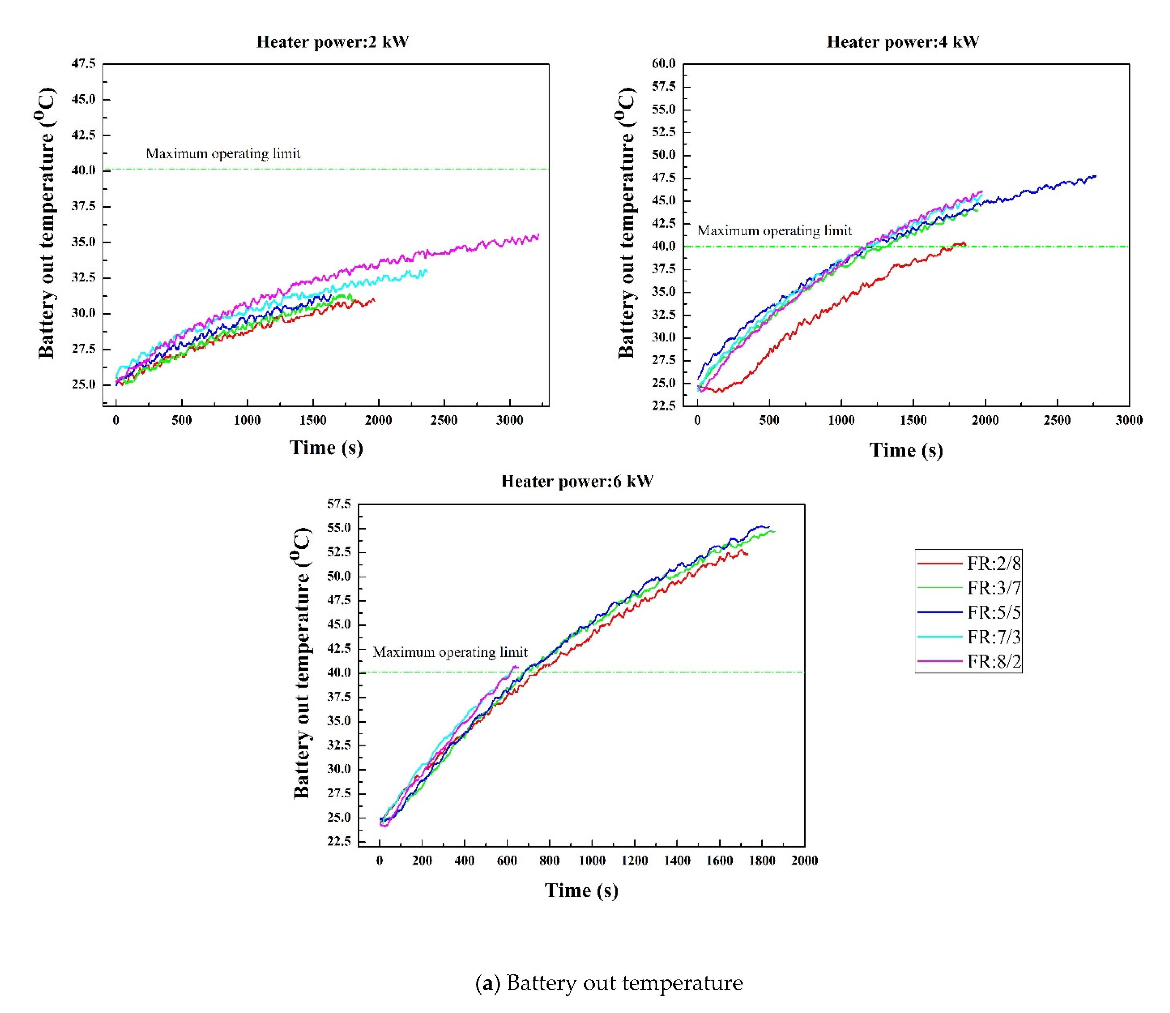
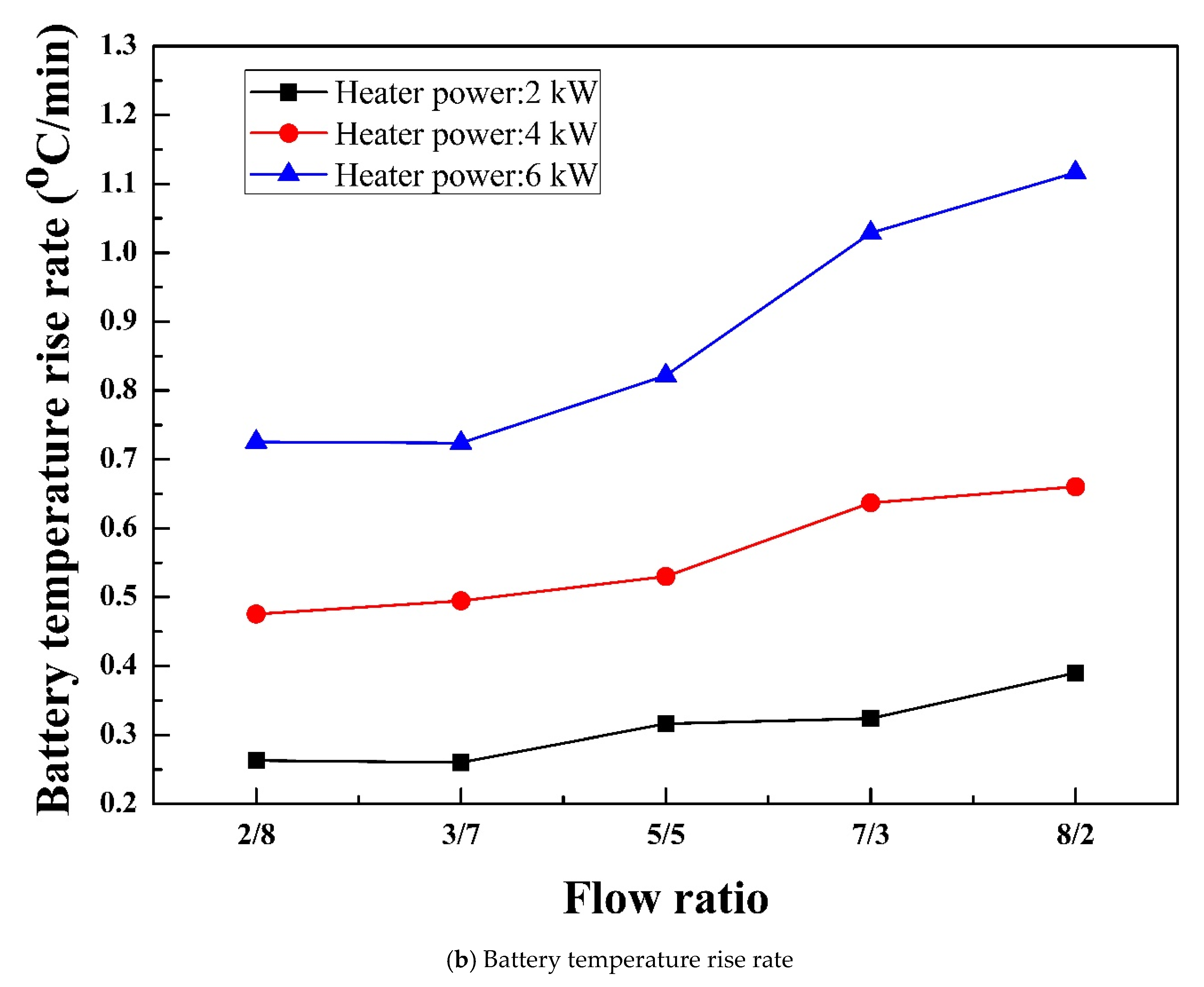
5.1.1. Battery out Temperature and Battery Temperature Rise Rate

The variation of battery out temperature with time for the integrated system with parallel circuit at various heater powers and flow ratios is presented in Figure 3a. The maximum battery heating temperature is cutoff at 40 °C because battery functions effectively below this temperature [8]. Therefore, the stopping criteria for the experiment at each flow rate and various heater powers is set as 40 °C, as shown in Figure 3a. The purpose of battery heating is to reach the maximum cut off temperature (40 °C) in minimum time using the proposed integrated heating system. If the experiment reaches the cut off temperature at any flow ratio and heater power, then it is stopped. However, if the experiments fail to reach cutoff temperature or the increasing gradient of temperature curve at any flow ratio and heater power is low then the experiment is stopped. For all flow ratios, as the heater power increases from 2 to 6 kW, the battery out temperature increases. This means higher heater power enables higher and faster heating of battery. A higher flow ratio indicates higher flow rate of working fluid for battery heating. Therefore, as the flow ratio increases from 2/8 to 8/2, the battery out temperature enhances towards the higher heating temperature. In the case of heater power of 2 kW, the battery heating temperature reaches to only 35 °C after 3000 s. The increasing gradient for each temperature curve increases slowly with time, hence, experiments are stopped on or before 3000 s, because, from the trends of temperature curve, it is not expected that they could reach to cutoff temperature. Whereas the battery heating temperature reaches to 40 °C within 2000 s for heater power of 4 kW and within 1000 s for heater power of 6 kW.
The variation of the battery temperature rise rate with flow ratio for the integrated system with parallel circuit at various heater powers is shown in Figure 3b. Due to an increase in the battery out temperature with increase in the heater power, the battery temperature rise rate enhances with heater power. In addition, the higher flow rate of working fluid for battery heating increases the battery temperature rise rate as the flow ratio increases. As the flow ratio increases from 2/8 to 8/2, the battery temperature rise rate increases by 48.20% for heater power of 2 kW, 38.90% for heater power of 4 kW and 53.90% for heater power of 6 kW. The maximum battery temperature rise rate for heater powers of 2 kW, 4 kW and 6 kW are observed 0.39 °C/min, 0.66 °C/min and 1.17 °C/min, respectively, at the flow ratio of 8/2.

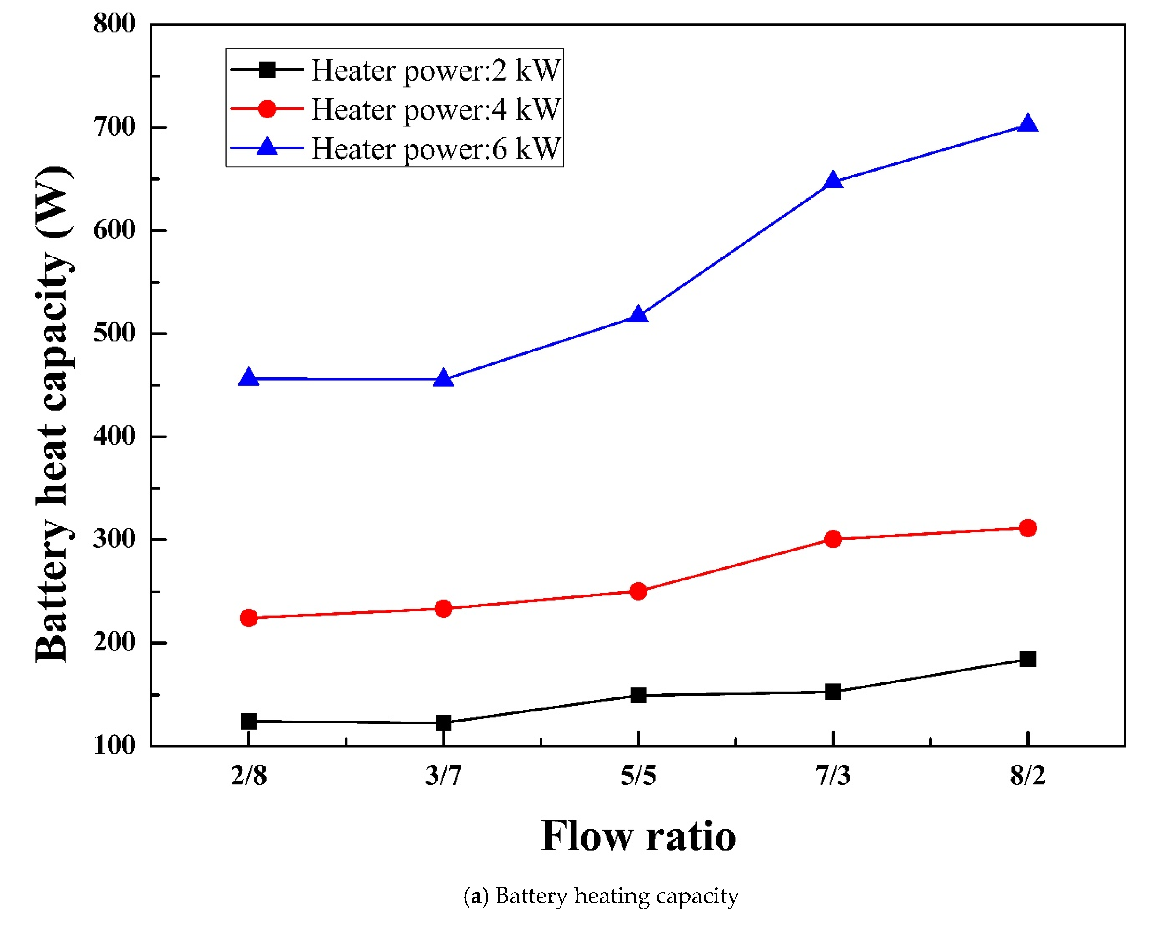
5.1.2. Battery and HVAC Heating Capacities

The behavior of battery heating capacity with flow ratio for the integrated system with a parallel circuit at various heater powers is shown in Figure 4a. The battery heating capacity increases with increase in flow ratio as well as heater power, due to an increase in the battery out temperature and the battery temperature rise rate with heater power and flow ratio. The battery heating capacity curves are less steep with the flow ratio for the lower heater powers of 2 kW and 4 kW, compared with the higher heater power of 6 kW. The battery heating capacities increase from 124.14 to 183.99 W, 224.62 to 311.65 W and 456.36 to 702.43 W for heater powers of 2 kW, 4 kW and 6 kW, respectively, when the flow ratio increases from 2/8 to 8/2. The maximum battery heating capacities for heater powers of 4 kW and 6 kW are higher by 69.30% and 281.70%, respectively, than that for heater power of 2 kW.
The effect of flow ratio and heater power on HVAC heating capacity of the integrated system with parallel circuit is presented in Figure 4b. The lower flow ratio indicates higher flow rate of working fluid through HVAC and vice versa. Therefore, the HVAC heating capacity is higher at the lower flow ratio and lower at the higher flow ratio. This means HVAC heating capacity decreases as the flow ratio increases for all heater powers. The HVAC heating capacities decrease by 26.50%, 39.40% and 50.00% for heater powers of 2 kW, 4 kW and 6 kW, respectively, as the flow ratio increases from 2/8 to 8/2. The decreasing curve of HVAC heating capacity are steeper at higher heater power compared with lower heater power. The maximum HVAC heating capacities for heater powers of 2 kW, 4 kW and 6 kW are observed at flow ratio of 2/8 which are 1315.50 W, 1915.22 W and 3482.23 W, respectively. Min et al. have proposed fuzzy logic based electric vehicle thermal management system to maintain the desire temperatures of battery and cabin [44]. Seo et al. have investigated heat transfer characteristics of an integrated heating system for thermal management of cabin and battery of electric vehicle [45]. In the case of the integrated system with a parallel circuit, the sum of heating capacities for battery and HVAC are not equivalent to the supplied input for all heater powers of 2 kW, 4 kW and 6 kW. The heat losses occurred in experimental components, valves, pipes, pipe fittings/connections and ambient from the heated working fluid.

5.2. Heating Performances of Battery and HVAC for Integrated System with Serial Circuit

The experimental results for battery and HVAC heating performances of the integrated system with serial circuit, such as battery out temperature, battery temperature rise rate, battery heating capacity and HVAC heating capacity at various heater powers are discussed in this section.

5.2.1. Battery out Temperature and Battery Temperature Rise Rate

The variation of battery out temperature with time for the integrated system with serial circuit at various heater powers is presented in Figure 5a. As the heater power increases from 2 kW to 6 kW, the battery out temperature increases. Hence, higher heater power shows faster battery heating performance compare with lower heater power. In the case of an integrated system with a serial circuit, full flow rate of working fluid is used in battery heating, therefore, the time needed to reach 40 °C is shorter than the integrated system with parallel circuit for all heater powers. The battery out temperature reaches to 40 °C within 400 s for 6 kW heater power, which is within 600 s for 4 kW heater power and that within 1200 s for 2 kW heater power. Ruan et al. have also shown the heating temperature behavior of single cell battery over the time. The battery heating from temperature of −30 °C to 2.1 °C is achieved within 103 s [5].
The variation of battery temperature rise rate of the integrated system with serial circuit for various heater powers is shown in Figure 5b. As a result of the increase in the battery out temperature with increase in the heater power, the battery temperature rise rate is higher at higher heater power. The battery temperature rise rates are 102.90% and 204.60% higher for heater powers of 4 kW and 6 kW, respectively, compared to the battery temperature rise rate at heater power of 2 kW. The battery temperature rise rate is higher for the integrated system with serial circuit compare to the integrated system with parallel circuit for all heater powers because full flow rate of working fluid is used for battery heating in the integrated system with serial circuit which significantly enhances the battery out temperature for the integrated system with serial circuit compared with the integrated system with parallel circuit. The battery temperature rise rates in the case of an integrated system with serial circuit are higher by 83.20%, 119.20% and 94.60% for heater powers of 2 kW, 4 kW and 6 kW, respectively, compared to the integrated system with parallel circuit. Guo et al. have achieved the battery cell heating from temperature of −20.30 °C to 10.02 °C within 13.70 min at an average temperature rise of 2.21 °C/min and battery pack heating from a temperature of −20.84 °C to 10 °C is achieved within 12.40 min at an average temperature rise of 2.47 °C/min [4].

5.2.2. Battery and HVAC Heating Capacities

The effect of heater power on battery heating capacity of the integrated system with serial circuit is shown in Figure 6a. Due to higher battery heating performance at higher heater power, the battery heating capacity increases with increase in the heater power. The battery heating capacities at heater powers of 2 kW, 4 kW and 6 kW are 336.37 W, 682.75 W and 1025.16 W, respectively. As a result of higher battery heating temperature of the integrated system with serial circuit compare to integrated system with parallel circuit for all heater powers, the battery heating capacities of integrated system with serial circuit for the heater powers of 2 kW, 4 kW and 6 kW are higher by 82.80%, 119.10% and 45.90%, respectively, than those of integrated system with parallel circuit.
The effect of heater power on HVAC heating capacity of the integrated system with serial circuit is shown in Figure 6b. As whole flow rate of working fluid is used for HVAC heating in the case of an integrated system with serial circuit, the HVAC heating capacity of integrated system with serial circuit is higher than that of integrated system with parallel circuit for all heater powers. The HVAC heating capacities of integrated system with serial circuit for heater powers of 2 kW, 4 kW and 6 kW are higher by 46.50%, 93.60% and 64.40%, respectively, than those of integrated system with parallel circuit. The HVAC heating capacity of integrated system with serial circuit also increases as the heater power increases. The HVAC heating capacities at heater powers of 4 kW and 6 kW are enhanced by 92.30% and 196.90%, compared to that of 2 kW. Zhang et al. have shown maximum cabin heating capacity of 2097 W using an economized vapor injection heat pump system whereas, Patil et al. have presented maximum cabin heating capacity of 2171.5 W using a 2.0 kW burner [11,20].

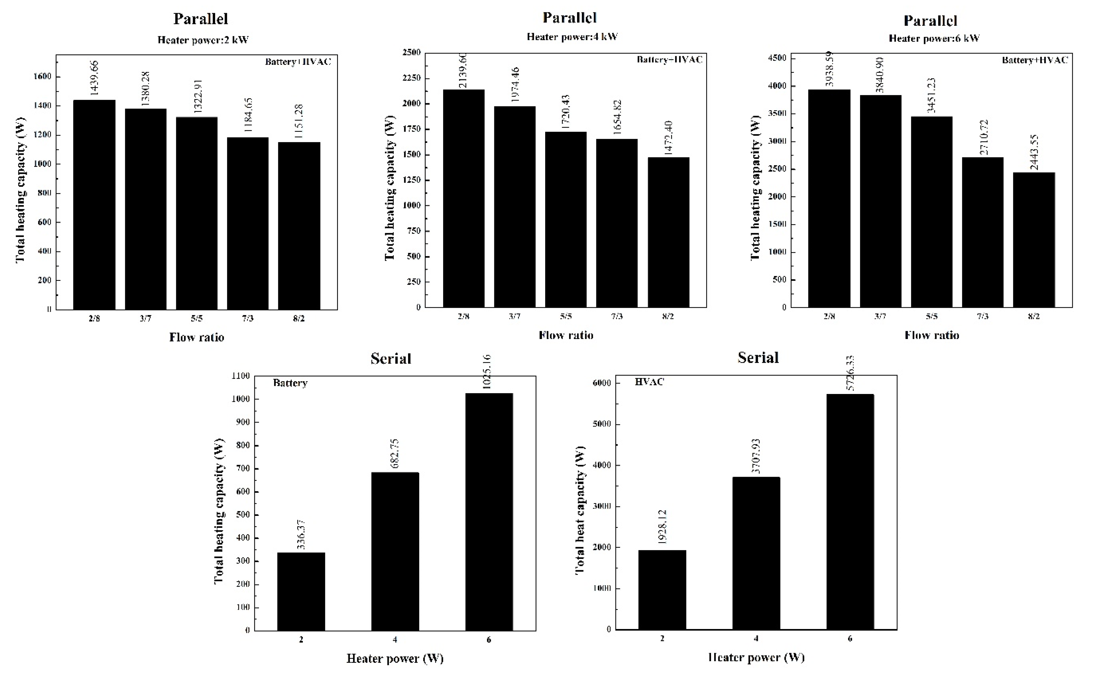
5.3. Total Heating Capacity of Integrated System with Serial and Parallel Circuits

The total heating capacities comparison of the integrated system with serial and parallel circuits for various heater powers is presented in Figure 7. In addition, in the case of an integrated system with parallel circuit, the effect of flow ratio on total heating capacity is also included. As presented in Figure 7, the total heating capacity for parallel circuit is the sum of heating capacities of battery and HVAC at all heater powers and flow ratios, whereas the total heating capacity for the serial circuit is the heating capacity of the battery when the battery only heated using an entire flow rate, and that is the heating capacity of HVAC when only HVAC is heated using a full flow rate of working fluid. In the integrated system with parallel circuit, the total flow rate of working fluid (24 L/min) is divided to heat up the battery and HVAC therefore, the total heating capacity is the sum of heating capacities of battery and HVAC. While, in the case of an integrated system with serial circuit, the total flow rate of working fluid is used for heating of battery or heating of HVAC, therefore, the heating capacity of the battery or heating capacity of HVAC is only the total heating capacity. In total, the heating capacity of the integrated system with parallel circuit, the heating capacity of HVAC is more dominant compare with heating capacity of battery. Therefore, the total heating capacity of the integrated system with parallel circuit decreases as the flow ratio increases for all heater powers because of decrease in the heating capacity of HVAC. The maximum total heating capacities for the integrated system with parallel circuit are found at flow ratio of 2/8 for heater powers of 2 kW, 4 kW and 6 kW, which are 1439.66 W, 2139.60 W and 3938.59 W, respectively. For the integrated system with serial and parallel circuits, the total heating capacity increases as the heater power increases. The total heating capacity increases by 173.50% for the integrated system with parallel circuit, 204.80% for battery heating of integrated system with serial circuit and 197% for HVAC heating of the integrated system with serial circuit, as the heater power increases from 2 kW to 6 kW. For heater power of 2 kW, the maximum total heating capacity of the integrated system with parallel circuit is 327.90% higher than total battery heating capacity of the integrated system with serial circuit, and that is 25.30% lower than total HVAC heating capacity of the integrated system serial circuit. At heater power of 4 kW, the total heating capacity of the integrated system with parallel circuit is 212.30% higher and 42.30% lower than the total battery heating capacity and total HVAC heating capacity of the integrated system with serial circuit, respectively. In the same way, at a heater power of 6 kW, the total heating capacity of integrated system with parallel circuit is 284.20% higher and 31.20% lower than the total battery heating capacity and total HVAC heating capacity of the integrated system with serial circuit, respectively. As shown in Figure 7, the output as the sum of heating capacities of battery and HVAC in the case of parallel circuit and heating capacity of battery or HVAC in the case of serial circuit are lower than the input as heater power. The heat losses for the integrated system with serial and parallel circuits are occurred into experimental components. as well as three valves, pipes and pipe fittings/connections. In addition, some heat loss occurs from working fluid to ambient. The integrated system with serial circuit shows rapid heating performance compared with the integrated system with parallel circuit, but the tradeoff heating between battery and HVAC is not possible in the case of the integrated system with serial circuit. However, the integrated system with parallel circuit enables the tradeoff between the heating of HVAC and that of the battery. Despite of slow heating performance of the integrated system with parallel circuit, the desired heating performance could be achieved.

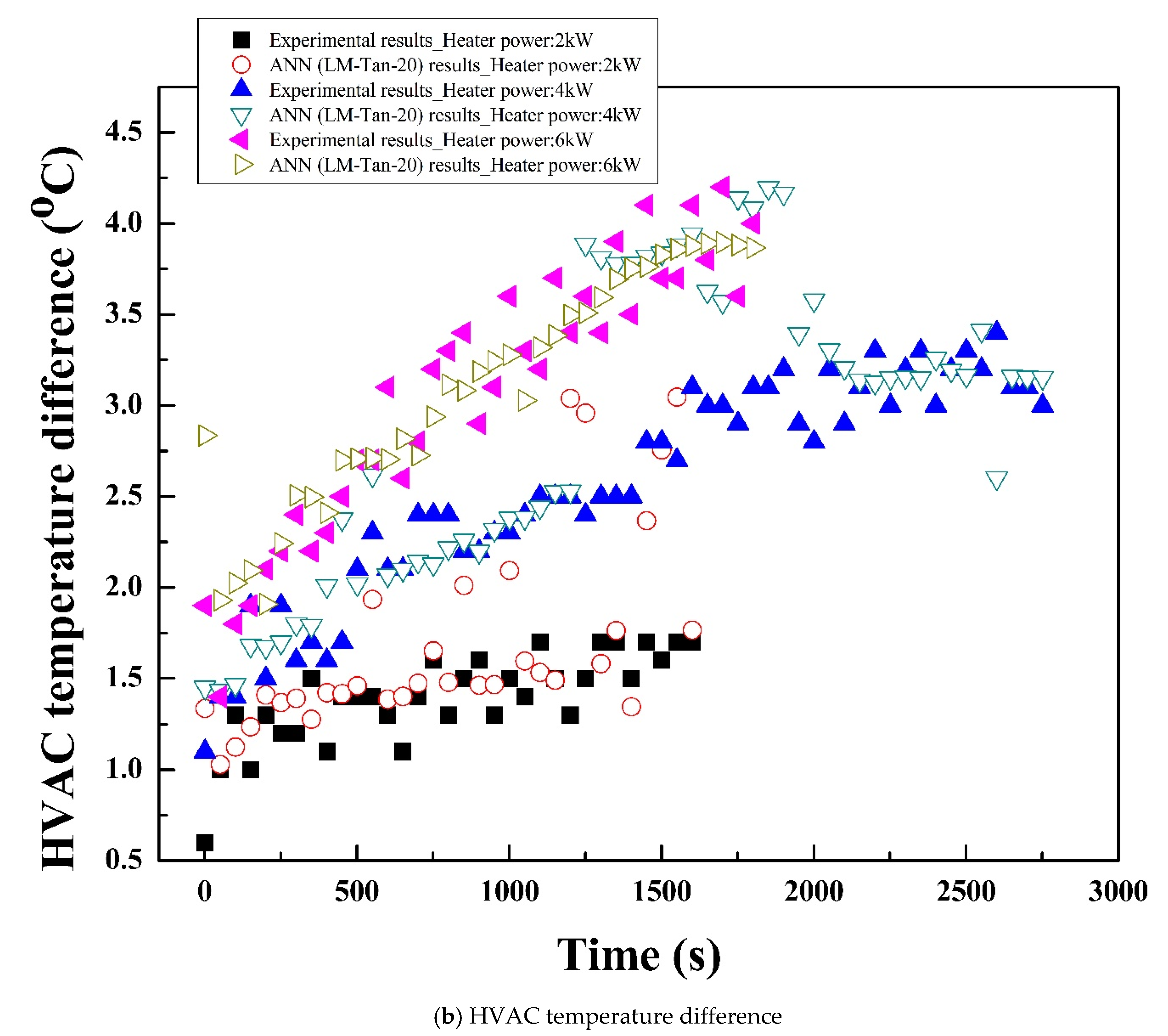
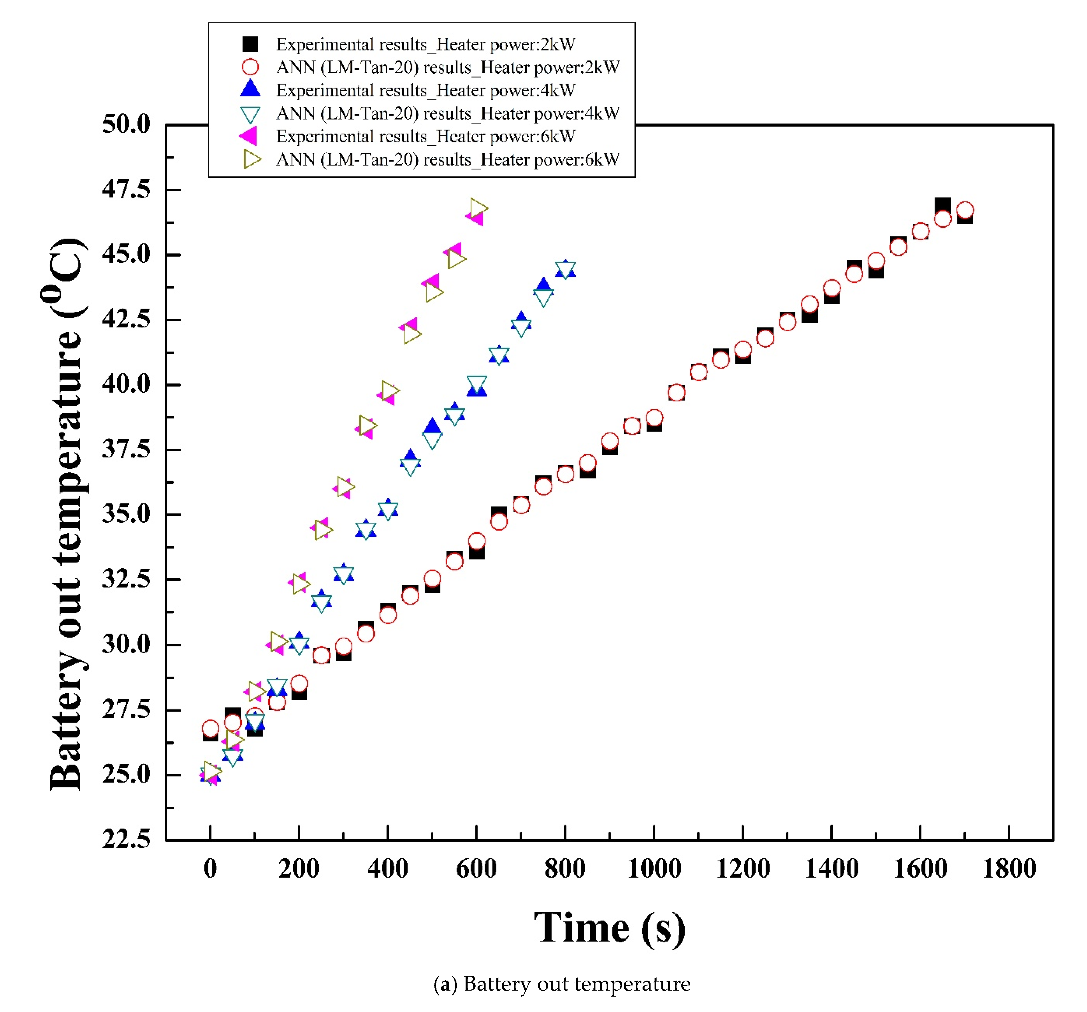
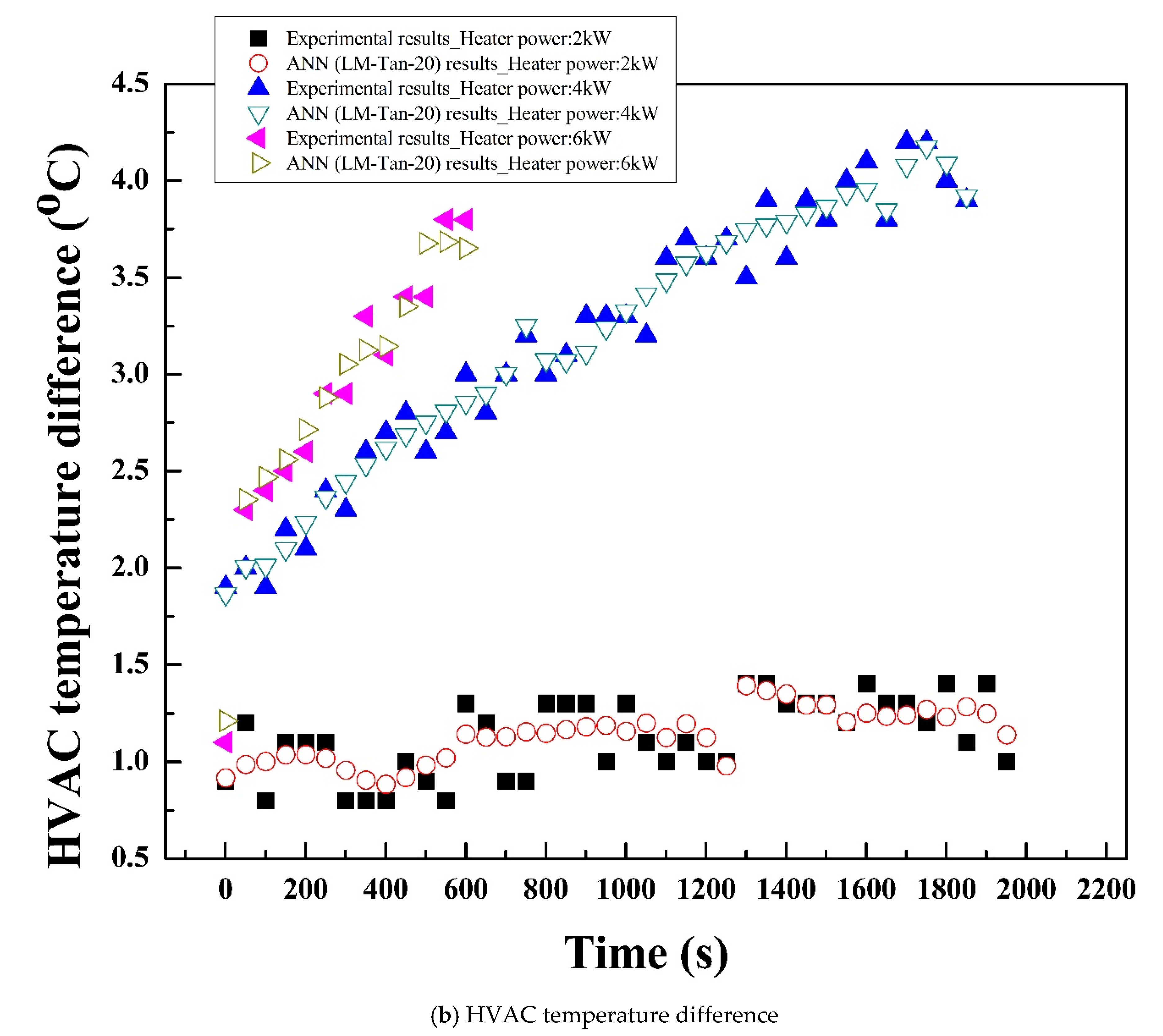
5.4. ANN Model for Battery and HVAC Heating Performances

The battery and HVAC heating performances of the integrated system with serial and parallel circuits predicted by ANN model with various algorithm are compared with corresponding experimental (actual) results. The comparison of predicted results and actual results is done in terms of three statistical parameters namely, coefficient of determination (R2), root mean square error (RMSE) and coefficient of variance (COV). The algorithm with highest value of R2 and lowest values of RMSE and COV are suggested as the optimum algorithm for ANN model.

5.4.1. Integrated System with Parallel Circuit

The battery out temperature of the integrated system with parallel circuit for various heater powers, flow ratios and time is predicted using various algorithms of ANN models. The experimental data of battery out temperature of the integrated system with parallel circuit at various time, flow rates and heater powers are used for the training, testing and validation of ANN models with various algorithms. The prediction accuracy of various algorithms of ANN model for battery out temperature at flow ratio of 5/5 and all heater powers is presented in Table 3. A higher prediction accuracy is obtained for other flow ratios as well. For all heater powers and hidden neurons, LM with Tan training variant shows better prediction accuracy compared to LM with Log training variant. In addition, prediction accuracy increases as the number of hidden neurons increases for all heater powers. Therefore, in respective case of each heater power, LM-Tan with 20 hidden neurons shows highest prediction accuracy for battery out temperature of the integrated system with parallel circuit. The prediction accuracy of ANN model with LM-Tan-20 algorithm for battery out temperature of the integrated system with parallel circuit is R2 with 0.999971, 0.999979 and 0.999979, RMSE with 0.154166, 0.183539 and 0.201043, as well as COV with 0.536230, 0.460489 and 0.472796 for heater powers of 2 kW, 4 kW and 6 kW, respectively. The comparison of battery out temperature of the integrated system with parallel circuit for experiment and ANN model with LM-Tan-20 algorithm at various heater powers is also presented in Figure 8a. Figure 8a shows the prediction capability of suggested algorithm and closeness of predicted results by suggested algorithm with the experimental results.
The same algorithms of the ANN model are used to predict the HVAC temperature difference of the integrated system with parallel circuit. The ANN model with various algorithms is trained, tested and validated for the experimental HVAC temperature difference data at various flow rates, heater powers and time. The prediction accuracy of various algorithms of ANN models is presented at flow ratio of 5/5 and all heater powers for HVAC temperature difference in Table 3. For other flow ratios, a higher prediction accuracy is also obtained. In the case of HVAC temperature difference of the integrated system with parallel circuit, the LM with Tan training variant also shows superior prediction accuracy than the LM with Log training variant for all heater powers. Additionally, higher number of hidden neurons shows higher prediction performance for all heater powers. For the HVAC temperature difference of the integrated system with parallel circuit, the LM-Tan-20 shows R2 of 0.803624, 0.956737 and 0.994077, RMSE of 0.631449, 0.549005 and 0.245819, as well as COV of 44.75612, 21.27336 and 7.909049 for heater powers of 2 kW, 4 kW and 6 kW, respectively. The prediction accuracy of the LM-Tan-20 algorithm is better for the battery out temperature than the HVAC temperature difference, because of linear trends of battery out temperature and zigzag trends of HVAC temperature difference for all heater powers. Figure 8b shows the closeness of LM-Tan-20 algorithm predicted HVAC temperature difference and corresponding actual results for all heater powers. For some points deviation between the predicted and actual results is larger because of zigzag trend of HVAC temperature difference curves at all heater powers, the suggested algorithm is not able to follow all points accurately. However, the minimum prediction accuracy is 0.8, which is an acceptable prediction performance for the suggested ANN model. Mohanraj et al. have suggested the Levenberg-Marquardt training algorithm as the optimum for the accurate performance prediction with maximum R2 of 0.999 and lowest values of RMSE and COV [39].

5.4.2. Integrated System with Serial Circuit

The battery out temperature of the integrated system with serial circuit is predicted for various algorithms of ANN model using heater power, flow rates and time as the input conditions. The experimental battery out temperature, heater powers and flow rates at various time are considered to train, test and validate the various algorithms of ANN model. The prediction accuracy of ANN model with various algorithms for battery out temperature of the integrated system with serial circuit at various heater powers is presented in Table 4. The prediction accuracy of ANN model with LM-Tan-20 algorithm is superior for all heater powers. LM-Tan-20 algorithm shows R2, RMSE and COV values of 0.999970, 0.205704 and 0.554591, respectively, at a heater power of 2 kW, those values of 0.999980, 0.170831 and 0.479862, respectively, at a heater power of 4 kW, and those values of 0.999982, 0.158077 and 0.431001, respectively, at heater power of 6 kW. The battery out temperatures predicted by the LM-Tan-20 algorithm for various time and heater powers are compared with the corresponding experimental values in Figure 9a. A higher degree of closeness between the actual and predicted results could be observed for the suggested algorithm of ANN model.
The experimental results of HVAC temperature difference, heater power, flow rates and time are used to train, test and validate the same algorithms of the ANN models. Trained ANN models are used to predict the HVAC temperature difference for various heater powers with time. Table 4 shows the prediction accuracy of various algorithms of the ANN model for HVAC temperature difference of the integrated system with serial circuit at various heater powers. ANN model with LM-Tan-20 algorithm is suggested as the optimum model, which shows higher value of R2 and lowest values of RMSE and COV. ANN model with LM-Tan-20 algorithm shows R2, RMSE and COV values of 0.987539, 0.128786 and 11.30589, respectively, at 2 kW heater power, those of 0.998338, 0.132884 and 4.164997, respectively, at 4 kW heater power and those of 0.998081, 0.134271 and 4.444122, respectively, at 6 kW heater power. Figure 9b shows the comparison of experimental HVAC temperature difference and LM-Tan-20 algorithm predicted HVAC temperature difference for various heater powers. For all heater powers, the predicted results show closer agreement with corresponding experimental results.
Based on the results discussed in Section 5.4.1 and Section 5.4.2, ANN model with LM-Tan-20 algorithm is suggested to accurately predict the heating performances of battery and HVAC for the integrated system with serial and parallel circuits. Kunal et al. proposed an ANN model with the optimum structure as the Levenberg-Marquardt training algorithm and Tan-sigmoidal transfer function for the accurate performance prediction [43].

6. Conclusions

An experimental study is conducted on the integrated system with serial and parallel circuits to investigate the heating performances of battery and HVAC for an electric vehicle. In addition, ANN models are developed to predict the battery and HVAC heating performances of the integrated system with serial and parallel circuits. The following findings are summarized from the present study.
(a)
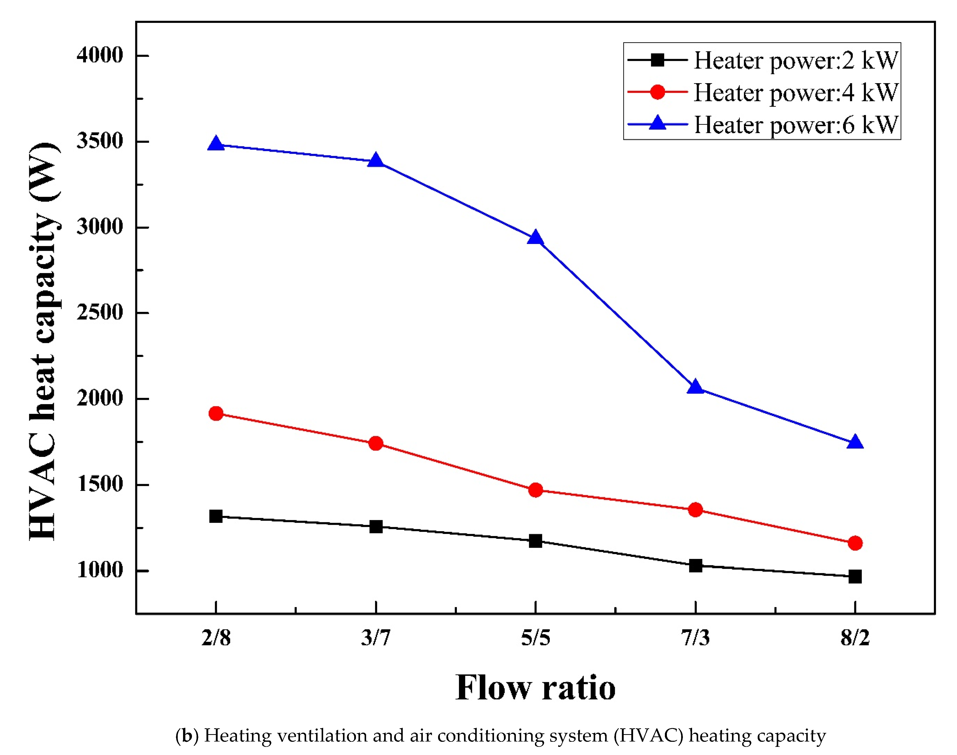
The effect of heater power on heating performances of the integrated system with serial and parallel circuits and effect of flow ratio on heating performances of the integrated system with parallel circuit are analyzed. As the heater power increases, the heating performances increases for the integrated system with serial and parallel circuits. With an increase in the flow ratio to the battery, battery heating performance enhances, whereas HVAC heating performance decreases.
(b)
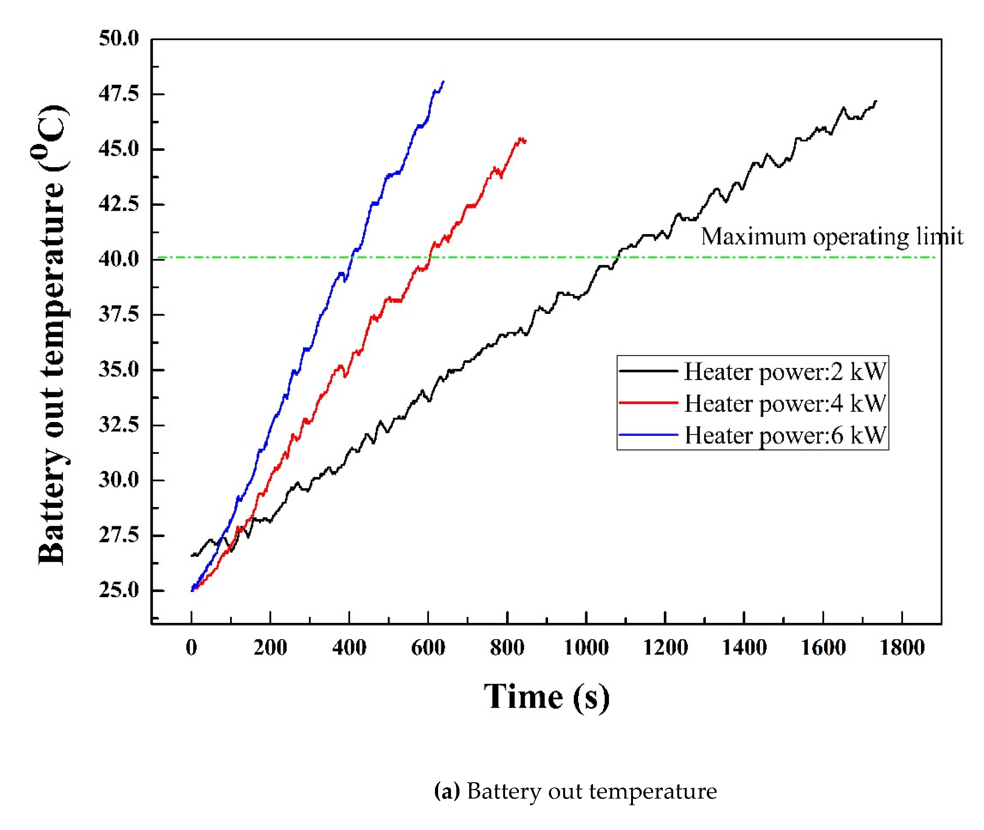
In the case of integrated system with parallel circuit, battery out temperature reaches 40 °C within 20 min at the rate of 1.22 °C/min. Battery heating capacity is evaluated as 764.99 W and HVAC heating capacity is evaluated as 3869.15 W.
(c)
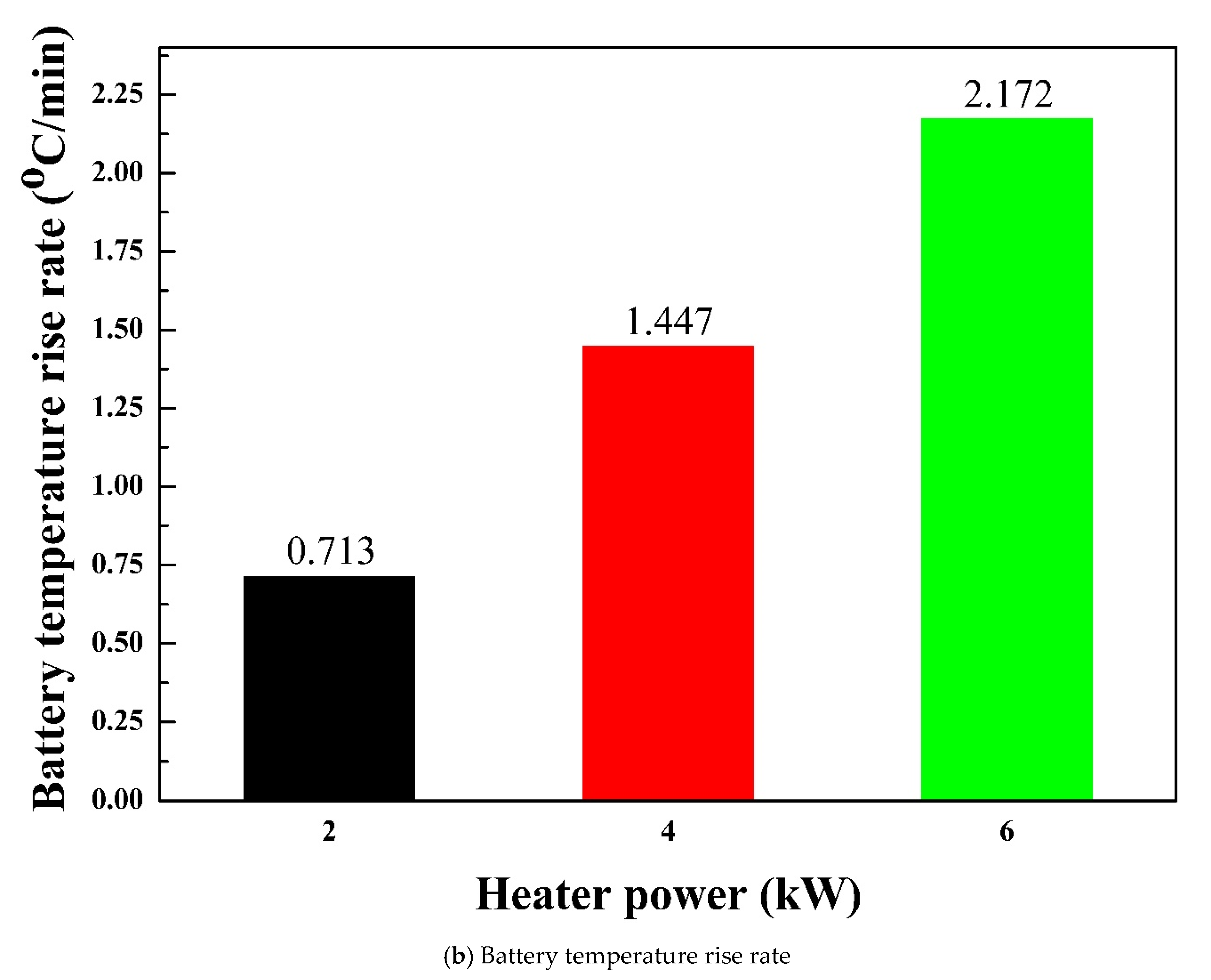
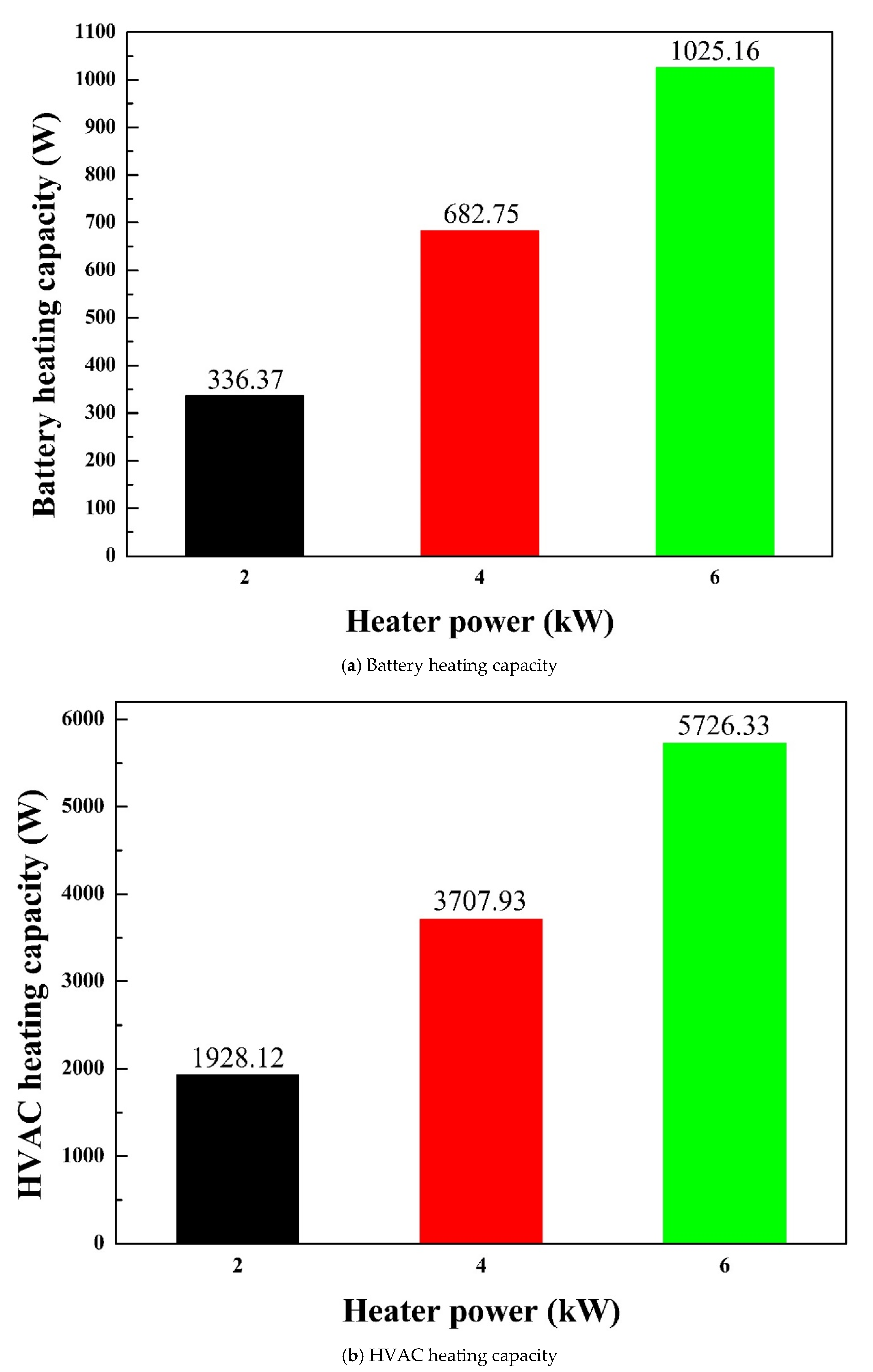
The battery out temperature reaches to 40 °C within 10 min at the rate of 2.17 °C/min for the integrated system with serial circuit. The battery and HVAC heating capacities for the integrated system with serial circuit are evaluated as 1025.16 W and 5726.33 W, respectively.
(d)
The integrated system with serial circuit enables faster heating performance than the integrated system with parallel circuit for both battery and HVAC. However, the integrated system with parallel circuit enables the tradeoff heating between battery and HVAC at the desired level with the slower rate.
(e)
The battery and HVAC heating performances of the integrated system with serial and parallel circuits are accurately predicted using the developed ANN models with back-propagation training algorithm, Levenberg-Marquardt training variant, Tan-sigmoidal transfer function and 20 hidden neurons.
(f)
The effects of various operating conditions on the heating performances of battery and HVAC using the proposed integrated system with serial and parallel circuits could be investigated and optimized, to find the optimum point for tradeoff heating of battery and HVAC under various conditions. The extracted results could be used in practical applications such as under cold weather conditions, the extracted optimum point for tradeoff heating of battery and HVAC could successfully achieve the efficient battery and HVAC heating performances of full size commercial electric vehicles with increased driving range and improved battery performance and life. The integrated system with serial circuit could be used for applications where rapid heating of battery or HVAC is needed, whereas the integrated system with parallel circuit could be used for applications where tradeoff simultaneous heating of battery and HVAC is needed. Thus, the proposed integrated system with serial and parallel circuits has the practical applicability to enable rapid, as well as tradeoff heating for both battery and HVAC in electric vehicles.

Author Contributions

Conceptualization, T.-K.L.; K.S.G.; J.-H.S. and M.-Y.L.; methodology, T.-K.L. and K.S.G.; formal analysis, T.-K.L. and K.S.G.; investigation, T.-K.L. and K.S.G.; resources, T.-K.L.; K.S.G. and J.-H.S.; data curation, T.-K.L.; K.S.G. and J.-H.S.; writing—original draft preparation, T.-K.L.; K.S.G.; J.-H.S. and M.-Y.L.; writing—review and editing, T.-K.L.; K.S.G., J.-H.S.; M.-Y.L. and D.-Y.L.; visualization, T.-K.L.; K.S.G. and J.-H.S.; supervision, M.-Y.L. and D.-Y.L.; project administration, T.-K.L.; M.-Y.L. and D.-Y.L.; funding acquisition, T.-K.L.; M.-Y.L. and D.-Y.L. All authors have read and agreed to the published version of the manuscript.

Funding

This research received no external funding.

Institutional Review Board Statement

Not applicable.

Informed Consent Statement

Not applicable.

Data Availability Statement

The data presented in this study will be available on request to the corresponding author.

Acknowledgments

This work was supported by the Technology Innovation Program (20011622, Development of battery pack system applied high efficiency heat control polymer and part component) funded by the Ministry of Trade, Industry & Energy (MOTIE, Korea), the National Research Foundation of Korea (NRF) grant funded by the Korea government (MSIT) (No. 2020R1A2C1011555) and the 2020 Yeungnam University Research Grant.

Conflicts of Interest

The authors declare no conflict of interest.

References

  1. Wu, S.; Xiong, R.; Li, H.; Nian, V.; Ma, S. The state of the art on preheating lithium-ion batteries in cold weather. J. Energy Storage 2020, 27, 101059. [Google Scholar]
  2. Kang, B.H.; Lee, H.J. A review of recent research on automotive HVAC systems for EVs. Int. J. Air-Cond. Refrig. 2017, 25, 1730003. [Google Scholar]
  3. Lei, Z.; Zhang, Y.; Lei, X. Temperature uniformity of a heated lithium-ion battery cell in cold climate. Appl. Therm. Eng. 2018, 129, 148–154. [Google Scholar]
  4. Guo, S.; Xiong, R.; Wang, K.; Sun, F. A novel echelon internal heating strategy of cold batteries for all-climate electric vehicles application. Appl. Energy 2018, 219, 256–263. [Google Scholar]
  5. Ruan, H.; Jiang, J.; Sun, B.; Su, X.; He, X.; Zhao, K. An optimal internal-heating strategy for lithium-ion batteries at low temperature considering both heating time and lifetime reduction. Appl. Energy 2019, 256, 113797. [Google Scholar]
  6. Lei, Z.; Zhang, Y.; Lei, X. Improving temperature uniformity of a lithium-ion battery by intermittent heating method in cold climate. Int. J. Heat Mass Transf. 2018, 121, 275–281. [Google Scholar]
  7. Shang, Y.; Zhu, C.; Lu, G.; Zhang, Q.; Cui, N.; Zhang, C. Modeling and analysis of high-frequency alternating-current heating for lithium-ion batteries under low-temperature operations. J. Power Sources 2020, 450, 227435. [Google Scholar]
  8. Fan, R.; Zhang, C.; Wang, Y.; Ji, C.; Meng, Z.; Xu, L.; Chin, C.S. Numerical study on the effects of battery heating in cold climate. J. Energy Storage 2019, 26, 100969. [Google Scholar]
  9. Reyes, J.R.M.D.; Parsons, R.V.; Hoemsen, R. Winter happens: The effect of ambient temperature on the travel range of electric vehicles. IEEE Trans. Veh. Technol. 2016, 65, 4016–4022. [Google Scholar]
  10. Qi, Z. Advances on air conditioning and heat pump system in electric vehicles–A review. Renew. Sust. Energ. Rev. 2014, 38, 754–764. [Google Scholar]
  11. Zhang, Z.; Li, W.; Shi, J.; Chen, J. A study on electric vehicle heat pump systems in cold climates. Energies 2016, 9, 881. [Google Scholar]
  12. Cho, C.W.; Lee, H.S.; Won, J.P.; Lee, M.Y. Measurement and evaluation of heating performance of heat pump systems using wasted heat from electric devices for an electric bus. Energies 2012, 5, 658–669. [Google Scholar]
  13. Qin, F.; Zhang, G.; Xue, Q.; Zou, H.; Tian, C. Experimental investigation and theoretical analysis of heat pump systems with two different injection portholes compressors for electric vehicles. Appl. Energy 2017, 185, 2085–2093. [Google Scholar]
  14. Qin, F.; Xue, Q.; Zhang, G.; Zou, H.; Tian, C. Experimental investigation on heat pump for electric vehicles with different refrigerant injection compressors. Energy Procedia 2015, 75, 1490–1495. [Google Scholar]
  15. Qin, F.; Xue, Q.; Velez, G.M.A.; Zhang, G.; Zou, H.; Tian, C. Experimental investigation on heating performance of heat pump for electric vehicles at− 20 C ambient temperature. Energy Convers. Manag. 2015, 102, 39–49. [Google Scholar]
  16. Ahn, J.H.; Kang, H.; Lee, H.S.; Jung, H.W.; Baek, C.; Kim, Y. Heating performance characteristics of a dual source heat pump using air and waste heat in electric vehicles. Appl. Energy 2014, 119, 1–9. [Google Scholar]
  17. Lee, H.S.; Won, J.P.; Cho, C.W.; Kim, Y.C.; Lee, M.Y. Heating performance characteristics of stack coolant source heat pump using R744 for fuel cell electric vehicles. J. Mech. Sci. Technol. 2012, 26, 2065–2071. [Google Scholar]
  18. Shi, Y.; Guo, X.; Zhang, X. Study on economized vapor injection heat pump system using refrigerant R32. Int. J. Air-Cond. Refrig. 2016, 24, 1650006. [Google Scholar]
  19. Jung, J.; Jeon, Y.; Lee, H.; Kim, Y. Numerical study of the effects of injection-port design on the heating performance of an R134a heat pump with vapor injection used in electric vehicles. Appl. Therm. Eng. 2017, 127, 800–811. [Google Scholar]
  20. Patil, M.S.; Cho, C.P.; Lee, M.Y. Numerical study on thermal performances of 2.0 kW burner for the cabin heater of an electric passenger vehicle. Appl. Therm. Eng. 2018, 138, 819–831. [Google Scholar]
  21. Zhang, L.; Hashimoto, K.; Hasegawa, H.; Saikawa, M. Performance analysis of a heat pump system with integrated desiccant for electric vehicles. Int. J. Refrig. 2018, 86, 154–162. [Google Scholar] [CrossRef]
  22. Choi, Y.U.; Kim, M.S.; Kim, G.T.; Kim, M.; Kim, M.S. Performance analysis of vapor injection heat pump system for electric vehicle in cold startup condition. Int. J. Refrig. 2017, 80, 24–36. [Google Scholar] [CrossRef]
  23. Kwon, C.; Kim, M.S.; Choi, Y.; Kim, M.S. Performance evaluation of a vapor injection heat pump system for electric vehicles. Int. J. Refrig. 2017, 74, 138–150. [Google Scholar] [CrossRef]
  24. Ahn, J.H.; Kang, H.; Lee, H.S.; Kim, Y. Performance characteristics of a dual-evaporator heat pump system for effective dehumidifying and heating of a cabin in electric vehicles. Appl. Energy 2015, 146, 29–37. [Google Scholar] [CrossRef]
  25. Lee, D.Y.; Cho, C.W.; Won, J.P.; Park, Y.C.; Lee, M.Y. Performance characteristics of mobile heat pump for a large passenger electric vehicle. Appl. Therm. Eng. 2013, 50, 660–669. [Google Scholar] [CrossRef]
  26. Liu, C.; Zhang, Y.; Gao, T.; Shi, J.; Chen, J.; Wang, T.; Pan, L. Performance evaluation of propane heat pump system for electric vehicle in cold climate. Int. J. Refrig. 2018, 95, 51–60. [Google Scholar] [CrossRef]
  27. Li, W.; Liu, R.; Liu, Y.; Wang, D.; Shi, J.; Chen, J. Performance evaluation of R1234yf heat pump system for an electric vehicle in cold climate. Int. J. Refrig. 2020, 115, 117–125. [Google Scholar] [CrossRef]
  28. Bellocchi, S.; Guizzi, G.L.; Manno, M.; Salvatori, M.; Zaccagnini, A. Reversible heat pump HVAC system with regenerative heat exchanger for electric vehicles: Analysis of its impact on driving range. Appl. Therm. Eng. 2018, 129, 290–305. [Google Scholar] [CrossRef] [Green Version]
  29. Lee, H.S.; Lee, M.Y. Steady state and start-up performance characteristics of air source heat pump for cabin heating in an electric passenger vehicle. Int. J. Refrig. 2016, 69, 232–242. [Google Scholar] [CrossRef]
  30. Lee, M.Y.; Garud, K.S.; Jeon, H.B.; Lee, H.S. A Study on Performance Characteristics of a Heat Pump System with High-Pressure Side Chiller for Light-Duty Commercial Electric Vehicles. Symmetry 2020, 12, 1237. [Google Scholar] [CrossRef]
  31. Jeffs, J.; McGordon, A.; Picarelli, A.; Robinson, S.; Tripathy, Y.; Widanage, W.D. Complex heat pump operational mode identification and comparison for use in electric vehicles. Energies 2018, 11, 2000. [Google Scholar] [CrossRef] [Green Version]
  32. Jeffs, J.; Dinh, T.Q.; Widanage, W.D.; McGordon, A.; Picarelli, A. Optimisation of Direct Battery Thermal Management for EVs Operating in Low-Temperature Climates. Energies 2020, 13, 5980. [Google Scholar] [CrossRef]
  33. Arun, K.R.; Kunal, G.; Srinivas, M.; Kumar, C.S.; Mohanraj, M.; Jayaraj, S. Drying of untreated Musa nendra and Momordica charantia in a forced convection solar cabinet dryer with thermal storage. Energy 2020, 192, 116697. [Google Scholar] [CrossRef]
  34. Garud, K.S.; Seo, J.H.; Patil, M.S.; Bang, Y.M.; Pyo, Y.D.; Cho, C.P.; Lee, M.Y. Thermal–electrical–structural performances of hot heat exchanger with different internal fins of thermoelectric generator for low power generation application. J. Therm. Anal. Calorim. 2020, 1–33. [Google Scholar] [CrossRef]
  35. Seo, J.H.; Garud, K.S.; Lee, M.Y. Grey Relational Based Taguchi Analysis on Thermal and Electrical Performances of Thermoelectric Generator System with Inclined Fins Hot Heat Exchanger. Appl. Therm. Eng. 2020, 116279. [Google Scholar] [CrossRef]
  36. Raj, A.K.; Kunal, G.; Srinivas, M.; Jayaraj, S. Performance analysis of a double-pass solar air heater system with asymmetric channel flow passages. J. Therm. Anal. Calorim. 2019, 136, 21–38. [Google Scholar] [CrossRef]
  37. Yazdani-Chamzini, A.; Zavadskas, E.K.; Antucheviciene, J.; Bausys, R. A model for shovel capital cost estimation, using a hybrid model of multivariate regression and neural networks. Symmetry 2017, 9, 298. [Google Scholar] [CrossRef] [Green Version]
  38. Garud, K.S.; Jayaraj, S.; Lee, M.Y. A review on modeling of solar photovoltaic systems using artificial neural networks, fuzzy logic, genetic algorithm and hybrid models. Int. J. Energy Res. 2020, 45, 6–35. [Google Scholar] [CrossRef]
  39. Mohanraj, M.; Jayaraj, S.; Muraleedharan, C. Performance prediction of a direct expansion solar assisted heat pump using artificial neural networks. Appl. Energy 2009, 86, 1442–1449. [Google Scholar] [CrossRef]
  40. Islam, K.T.; Raj, R.G.; Mujtaba, G. Recognition of traffic sign based on bag-of-words and artificial neural network. Symmetry 2017, 9, 138. [Google Scholar] [CrossRef] [Green Version]
  41. Moya-Rico, J.D.; Molina, A.E.; Belmonte, J.F.; Tendero, J.C.; Almendros-Ibanez, J.A. Characterization of a triple concentric-tube heat exchanger with corrugated tubes using Artificial Neural Networks (ANN). Appl. Therm. Eng. 2019, 147, 1036–1046. [Google Scholar] [CrossRef]
  42. Şahin, A.Ş. Performance analysis of single-stage refrigeration system with internal heat exchanger using neural network and neuro-fuzzy. Renew. Energy 2011, 36, 2747–2752. [Google Scholar] [CrossRef]
  43. Garud, K.S.; Seo, J.H.; Cho, C.P.; Lee, M.Y. Artificial Neural Network and Adaptive Neuro-Fuzzy Interface System Modelling to Predict Thermal Performances of Thermoelectric Generator for Waste Heat Recovery. Symmetry 2020, 12, 259. [Google Scholar] [CrossRef] [Green Version]
  44. Min, H.; Zhang, Z.; Sun, W.; Min, Z.; Yu, Y.; Wang, B. A thermal management system control strategy for electric vehicles under low-temperature driving conditions considering battery lifetime. Appl. Therm. Eng. 2020, 181, 115944. [Google Scholar] [CrossRef]
  45. Seo, J.H.; Patil, M.S.; Cho, C.P.; Lee, M.Y. Heat transfer characteristics of the integrated heating system for cabin and battery of an electric vehicle under cold weather conditions. Int. J. Heat Mass Transf. 2018, 117, 80–94. [Google Scholar] [CrossRef]
Figure 1. (a) Schematic diagram and (b) picture for experimental set-up of integrated system with serial and parallel circuits.
Symmetry 13 00093 g001
Figure 2. Artificial neural network (ANN) model for integrated system with serial and parallel circuits.
Symmetry 13 00093 g002
Figure 3. Variation of (a) battery out temperature and (b) battery temperature rise rate of parallel circuit for various heater power and flow ratios.
Symmetry 13 00093 g003aSymmetry 13 00093 g003b
Figure 4. Variation in (a) battery heating capacity and (b) HVAC heating capacity of parallel circuit with flow ratios for various heater powers.
Symmetry 13 00093 g004aSymmetry 13 00093 g004b
Figure 5. Variation of (a) Battery out temperature and (b) Battery temperature rise rate of serial circuit for various heater power.
Symmetry 13 00093 g005aSymmetry 13 00093 g005b
Figure 6. Effect of heater power on (a) battery heating capacity and (b) HVAC heating capacity of serial circuit.
Symmetry 13 00093 g006
Figure 7. Comparison of total heating capacities of parallel and serial circuits for various heater powers.
Symmetry 13 00093 g007
Figure 8. Comparison of (a) battery out temperature and (b) HVAC temperature difference of parallel circuit for experimental and ANN model with LM-Tan-20 algorithm at various heater powers.
Symmetry 13 00093 g008aSymmetry 13 00093 g008b
Figure 9. Comparison of (a) battery out temperature and (b) HVAC temperature difference of serial circuit for experimental and ANN model with LM-Tan-20 algorithm at various heater powers.
Symmetry 13 00093 g009aSymmetry 13 00093 g009b
Table 1. The specifications of components of experimental set-up.
ComponentSpecification
PipeMaterial: stainless
HeaterType: sheath
Water pumpMax flow: 25 L/min
Max head: 25 m
Power voltage: 24 VCD
RadiatorApplied vehicle: GM Volt
Core size: 147 × 206 × 28 mm
HVACApplied vehicle: Kona
Core size: 152 × 222 × 26 mm
Heater510 V, 11.8 A
Table 2. Accuracy of various experimental devices and instruments.
Device/InstrumentAccuracy
T-type thermocouple0.75%
DAQ−200 °C ≤ TS ≤ −100 °C, ± (0.10% of reading)
−100 °C ≤ TS ≤ 400 °C, ± (0.10% of reading)
Flow rate sensor±1.50%
Table 3. Prediction accuracy of ANN models for battery heating performance and HVAC heating performance of integrated system with parallel circuit.
Heater PowerAlgorithmNumber of Hidden NeuronsR2RMSECOV
Battery heating performance2 kWLM-Tan100.9999640.1720150.598317
150.9999650.1700360.591433
200.9999710.1541660.536230
LM-Log100.9999620.1766310.614369
150.9999650.1701200.591725
200.9999680.1630480.567126
4 kWLM-Tan100.9999760.1970360.494352
150.9999780.1899690.476623
200.9999790.1835390.460489
LM-Log100.9999760.1985850.498239
150.9999760.1969350.494101
200.9999780.1874250.470238
6 kWLM-Tan100.9999750.2186500.514204
150.9999760.2113990.497152
200.9999790.2010430.472796
LM-Log100.9999310.3603430.847426
150.9999760.2125660.499896
200.9999770.2080560.489290
HVAC heating performance2 kWLM-Tan100.7869290.65774246.61972
150.7980380.64036645.38813
200.8036240.63144944.75612
LM-Log100.7851270.66051946.81651
150.7946510.64571445.76716
200.7999470.63733245.17311
4 kWLM-Tan100.9556190.55605821.54665
150.9560400.55340821.44398
200.9567370.54900521.27336
LM-Log100.9540560.56576321.92271
150.9556870.55562621.52991
200.9565730.55004721.31374
6 kWLM-Tan100.9933040.2613628.409131
150.9937370.2527758.132854
200.9940770.2458197.909049
LM-Log100.9918770.2878649.291802
150.9935620.2562738.245384
200.9937480.2525388.125237
Table 4. Prediction accuracy of ANN models for battery heating performance and HVAC heating performance of integrated system with serial circuit.
Heater PowerAlgorithmNumber of Hidden NeuronsR2RMSECOV
Battery heating performance2 kWLM-Tan100.9999630.2272450.612664
150.9999660.2208350.595383
200.9999700.2057040.554591
LM-Log100.9999610.2347870.632999
150.9999640.2265660.610835
200.9999670.2161580.582773
4 kWLM-Tan100.9999790.1649970.463474
150.9999780.1975460.470634
200.9999800.1708310.479862
LM-Log100.9999690.2015670.566196
150.9999780.1705910.479186
200.9999800.1613140.453130
6 kWLM-Tan100.9999720.1989390.542413
150.9999810.1641240.447487
200.9999820.1580770.431001
LM-Log100.9999670.2148500.585792
150.9999750.1880600.512750
200.9999810.1619960.441684
HVAC heating performance2 kWLM-Tan100.9868860.13211811.59836
150.9871960.13054911.46062
200.9875390.12878611.30589
LM-Log100.9868810.13214211.60054
150.9870860.13110511.50950
200.9872260.13039311.44697
4 kWLM-Tan100.9980910.1424134.463665
150.9981370.1406894.409637
200.9983380.1328844.164997
LM-Log100.9980290.1446874.534949
150.9981060.1418714.446673
200.9982290.1371824.299688
6 kWLM-Tan100.9977890.1440904.769143
150.9978640.1416694.688989
200.9980810.1342714.444122
LM-Log100.9977790.1444454.780861
150.9978150.1432604.741652
200.9978940.1406714.655938
Publisher’s Note: MDPI stays neutral with regard to jurisdictional claims in published maps and institutional affiliations.

