Coupled Engine-Propeller Selection Procedure to Minimize Fuel Consumption at a Specified Speed


Centre for Marine Technology and Ocean Engineering (CENTEC), Instituto Superior Técnico, Universidade de Lisboa, Av. Rovisco Pais 1, 1049-001 Lisboa, Portugal
*
Author to whom correspondence should be addressed.
†
On leave from the Department of Naval Architecture and Marine Engineering, Faculty of Engineering, Alexandria University, Alexandria 21544, Egypt.
J. Mar. Sci. Eng. 2021, 9(1), 59; https://doi.org/10.3390/jmse9010059
Submission received: 18 December 2020
/
Revised: 2 January 2021
/
Accepted: 5 January 2021
/
Published: 7 January 2021
(This article belongs to the Special Issue Ship Routing)
Abstract
:This study presents a practical optimization procedure that couples the NavCad power prediction tool and a nonlinear optimizer integrated into the Matlab environment. This developed model aims at selecting a propeller at the engine operating point with minimum fuel consumption for different ship speeds in calm water condition. The procedure takes into account both the efficiency of the propeller and the specific fuel consumption of the engine. It is focused on reducing fuel consumption for the expected operational profile of the ship, contributing to energy efficiency in a complementary way as ship routing does. This model assists the ship and propeller designers in selecting the main parameters of the geometry, the operating point of a fixed-pitch propeller from Wageningen B-series and to define the gearbox ratio by minimizing the fuel consumption of a container ship, rather than only maximizing the propeller efficiency. Optimized results of the performance of several marine propellers with different number of blades working at different cruising speeds are also presented for comparison, while verifying the strength, cavitation and noise issues for each simulated case.
1. Introduction
Many actions are being taken towards climate change mitigation to reduce the amount of fuel consumption and exhaust emissions from ships. As mentioned by Lloyd’s Register [1] the different parts of the ships must be optimized in order to increase the energy efficiency of the ship by minimizing the total resistance [2,3] and thus reducing the required power and the fuel consumption along the ship trip [4,5,6,7].
Shipping companies are striving every day for improving their competitiveness, in some cases setting dedicated workings groups to continuously monitor the performance of their ships and to provide recommendations to improve navigation efficiency, reducing year by year the fleets operational costs [8,9], as well as the carbon footprint under the increasing pressure of the international community [10,11].
The objective of improving efficiency must be tackled from different perspectives: from the design stage, e.g., with the optimal design of the hull [12] and the selection of the propeller to match hull requirements and engine performance [13]; to the operational life, with an adequate trade-off between environmental and economic considerations [14], enhanced logistic [15] and optimal route selection and speed profile [16,17,18]. The impact of fuel consumption on operational ship costs follows the aleatory nature of oil market prices, however, as shown in Ronen [19], for large ships it may reach up to 75% of it. Consequently, a relatively small improvement in the efficiency can lead to tremendous effects on the budget of the company, justifying the continuous research of innovative solution in all aspects of ship design and operation.
A correct match between the engine and the propeller is an essential pre-requisite to achieve efficiency in ship operations, thus one cannot refrain from a holistic optimisation of the propulsion system. Moreover, the capability of accurately modelling the engine performance plays a fundamental role in routing problems, enabling to define the operating point of the engine and to realistically estimate fuel consumption, with a direct effect on the decision to be taken among different alternatives.
Regarding the propeller, which is the focus of this work, optimization procedures are applied in several research papers to maximize its performance. The efficiency of B-screw propeller is maximized by Benini [20], and the cavitation limits are verified using multi-objective optimization method. By modifying the expanded area ratio of the propeller blades, Lee et al. [21] increased the propeller efficiency by 2%. Vesting and Bensow [22] used a genetic algorithm (GA) to maximize the propeller efficiency and to minimize the pressure pulses. Xie [23] applied an adapted non-dominated sorting genetic algorithm (NSGA II) to generate the Pareto frontier in order to find the best solution corresponding to the maximum value of both thrust coefficient and propeller efficiency. The multi-objective particle swarm optimization (MOPSO) is also used to find the optimal propeller shape by maximizing efficiency while minimizing the cavitation [24]. Lee et al. [25] coupled optimization procedures and a lifting surface method in a three-dimensional mode to find the propeller shape of a complex propeller by determining the optimum circulation distribution. Gaggero et al. [26] combined a boundary elements method (BEM) and a GA to improve propulsive efficiency. This model helps to reduce the effect of cavitation and increase ship speed. This model helps to find a reliable propeller geometry for a high-speed craft. Nouri et al. [27] coupled a computational fluid dynamics (CFD) model, a genetic algorithm and a kriging method to find the optimal geometry of a contra-rotating propeller. The model shows an excellent ability to perform the simulation in a short period. The propeller geometry of a container ship is also optimized by Tadros et al. [28] to maximize the propeller efficiency and to verify the cavitation limits by coupling OpenProp software [29], that is based on lifting line theory, and implemented in Matlab environment. The OpenProp software is also coupled to the particle swarm optimization algorithm by Bacciaglia et al. [30] to optimize the efficiency of a controllable pitch propeller in terms of engine fuel consumption. At the same time, Tadros et al. [13] selected the most favourable propeller in terms of propeller efficiency to work at the minimum brake specific fuel consumption (BSFC) along the engine load diagram. In order to compare the performance of a propeller of a trawler vessel based on propeller efficiency and fuel consumption, Tadros et al. [31] developed an optimization procedure to easily select the optimum characteristics of the propeller. The computed results show a significant reduction in the fuel consumption when the propeller is optimized at the minimum fuel consumption in comparison with maximizing the efficiency of propeller or minimizing the BSFC along the engine load diagram.
In this study, the research work is extended to develop a pioneer propeller optimization model that couples NavCad [32] and a nonlinear optimizer in the Matlab environment. This model assists in the selection of an efficient fixed pitch propeller (FPP) from Wageningen B-series [33,34] in terms of fuel consumption by optimizing the propeller geometry and the gearbox ratio at the cruising speed to be used during the preliminary stage of ship design. Due to the increase in fuel costs, the ship is designed to move with a certain speed (design speed), but in practice, she does not exceed a speed (cruising speed) which is much lower than the design speed according to the opinion of experts working onboard, who ensure that this speed is practised most of the sailing time. Therefore, the propeller is optimized at the cruising speed instead of the design speed.
The model helps to compare between various marine propellers with different blades to thrust the ship at the cruising speed, at the operating point, with minimum fuel consumption of the installed engine, instead of only maximizing the propeller efficiency or minimizing the BSFC. In addition, the developed model verifies the different cavitation criteria, blade strength and noise issues.
The rest of the paper is organized as follows: Section 2 gives a general presentation of the selected ship and the installed engine; Section 3 describes the optimization model, the equations used in simulation and provides an overview of the main methods considered to compute the cavitation, strength and noise; the results are discussed in Section 4, and finally, some conclusions are presented in Section 5.
2. Ship and Engine Specifications
The numerical simulation is performed based on the collected data of a 111.18 m long containership, as shown in Table 1. The ship is equipped with one engine coupled with one propeller through a gearbox, which reduction ratio is to be optimized. Although containerships are generally employed on strict schedule voyages, a certain flexibility in the sailing speed can be attained by improving the logistic chain and the efficiency in port operations. As shown in Section 4, a minor reduction in operating speed can have a considerable impact on the travel costs, especially when the propeller is selected, taking into account such a reduced speed.
3. Numerical Model
3.1. General Overview
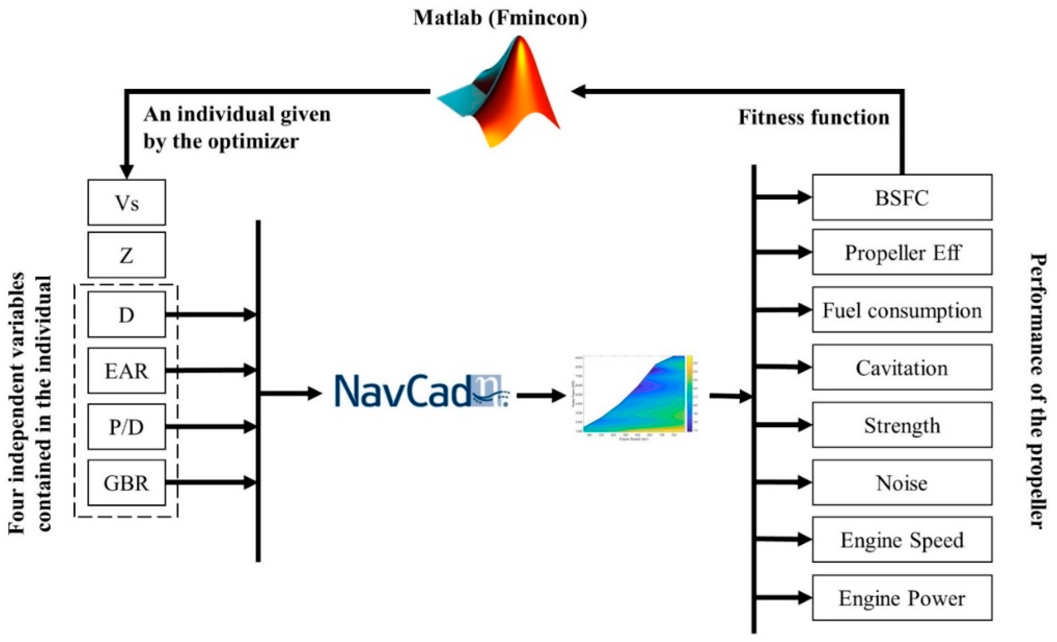
A propeller optimization model is developed coupling NavCad, a software tool used to predict the power requirements of a given vessel, and a nonlinear optimizer integrated into Matlab, as shown in Figure 1. The model helps to find the optimal values of the propeller geometry presented by the propeller diameter, D, the expanded area ratio, EAR, and the pitch diameter ratio, P/D, and the gearbox ratio, GBR, for a given vessel speed, vs. and number of propeller blades, Z, by minimizing the fuel consumption, FC, of the ship based on the computed engine load diagram. Also, the model helps to verify the cavitation limits, the strength issues and the propeller tip speed to avoid noise problems. In this optimization model, the objective, the boundary limits, and the constraints are well defined.
The model helps to find the optimal values of the propeller geometry presented by the propeller diameter, D, the expanded area ratio, EAR, and the pitch diameter ratio, P/D, and the gearbox ratio, GBR, for a given vessel speed, vs. and number of propeller blades, Z, by minimizing the fuel consumption, FC, of the ship based on the computed engine load diagram. Also, the model helps to verify the cavitation limits, the strength issues and the propeller tip speed to avoid noise problems. In this optimization model, the objective, the boundary limits, and the constraints are well defined.
For this nonlinear problem, it is necessary to convert the optimization with constraints to another one without constraints. So, the fitness function, including the objective of this study and the constraints, will be the objective function of the optimization model. There are different ways to implement a fitness function for the constrained optimization problems [36]. It can be based on the death penalty, static penalties, dynamic penalties, annealing penalties, adaptive penalties. These methods are prepared for genetic algorithm method; however, it can be applied for the nonlinear optimization method used in this study. In previous research, the simple penalty function method shows effectiveness for many optimization projects [37].
In order to construct the fitness function, the first part includes the objective of the model to be minimized, which is the fuel consumption per nautical mile, while the inequality constraints, as described in the following Section 3.3 and Section 3.4, are combined and defined as a static penalty function in the second part of the fitness function. The inequality constraints are normalized, so their absolute values will be less than one. Then, the fitness function for the optimization model is written as in the following expression, and the penalty parameter (R) is determined by 1000 after making many trials and as suggested by [38].
where g(x) is the static penalty function, j is the number of constraints, and x is the number of variables of the optimization problem.
The single objective nonlinear optimizer (fmincon) integrated into Matlab is used to search the minimum optimal solution of the problem by evaluating the proposed fitness function. This optimizer is based on the interior-point algorithm [39], and can reach the optimal solution faster than other optimizers [40].
As this optimizer is designed to search for the local minimum of any numerical problem, multi-starts are performed to define the minimum value of the fitness function and to verify all the constraints.
3.2. NavCad Software
NavCad is a software tool used to predict and analyse the power requirements of any ship in a steady-state mode, for a given range of ship speeds and to select the components of the propulsion system, based on a very comprehensive library of algorithms.
Once the hull data has been defined, the resistance and the propulsion are predicted by selecting the suitable computational methods. Then, the overall performance of the ship can be analysed manually or based on optimization routines.
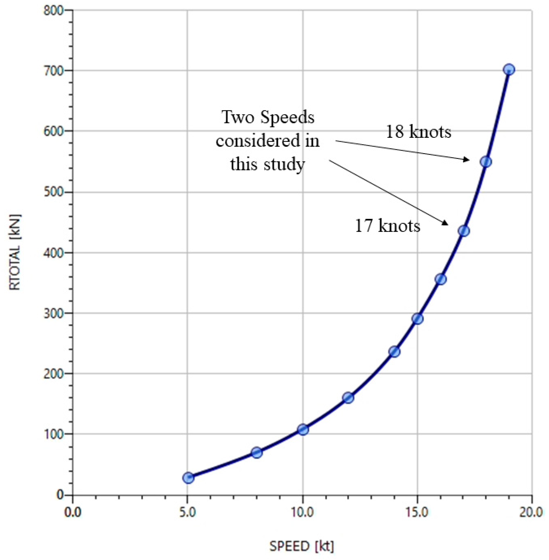
The data of the chosen container ship and the installed engine are specified in NavCad, in which the total resistance is computed based on the method suggested by Holtrop and Mennen [41] and Holtrop [42] for a given range of ship speeds, as shown in Figure 2. Two cruising speeds (17 and 18 knots) are selected to perform the simulation. Then the geometry of the propeller and the gearbox ratio are sized “by power” taking into account the wake fraction and thrust deduction fraction through the optimization routines.
3.3. Engine Performance
The performance of the selected engine is computed based on another optimization model developed by Tadros et al. [38]. The model is built in 1D engine simulation software, by taking into account the considered technologies such as variable valve timing, miller cycle, high compression ratio and fuel injection system techniques, to optimize the performance of the engine and to ensure an actual diesel combustion process [43,44].
For more realistic simulation, the operational area of the engine load diagram is limited from 60% to 90% of the maximum engine load and from 85% to 100% of the maximum engine speed. In this engine operating area, the nonlinear optimizer searches for the optimal design of the propeller for the cruising ship speed instead of the whole engine operating range to ensure better combustion and engine safety according to the recommendations of the engine manufacturer [35] and thus better engine performance. Otherwise, the engine cannot operate out of this range for more than 2 h.
3.4. Propeller Performance
The propeller performance is calculated using the regression equations from Wageningen B-series [33,34] integrated into NavCad to compute the thrust and torque coefficients and the propeller efficiency as presented in:
by considering the corrections made due to the change in values of Reynolds numbers, Rn, and propeller-hull interaction coefficients as follows:
where w is the wake fraction, t is the thrust deduction factor, VA is the advance speed, RT is the total ship resistance, n is the propeller speed, KT is the thrust coefficient, KQ is the torque coefficient, ηo is the propeller efficiency, and J is the advance coefficient. Cn, Sn, tn, un and vn are constants, and it important to mention that even the parameters have the same symbols, they have different values for the KT and KQ [47]. n is the propeller speed, ρ is the density, ν is the kinematic viscosity of the water, T is the thrust and Q is the torque.
The propeller cavitation is a crucial issue to be considered during the design stage. It occurs when the water pressure surrounding the propeller has reached a level below the water’s vapour pressure where the liquid states change into a vapor under a vacuum.
Three different methods can be used to assess the cavitation: Keller, average loading pressure and average predicted back cavitation percentage [47].
Based on the Keller method, the minimum blade area ratio, EARmin, that avoids cavitation is calculated using Equation (12):
where T is the propeller thrust, Patm is the atmospheric pressure, Pv is the vapour pressure, γ is the specific weight, h is the propeller centerline immersion, and k is a constant obtained from Equation (13):
The average loading pressure is the second method to assess the cavitation limit. Based on the criteria considered in HydroComp [32] derived from the Burrill chart [48], the value of the average loading pressure must not exceed 65 kPa.
The back cavitation is the harmful type of cavitation which generated from the too much power through the propeller and the insufficient blades area to handle the developed thrust. Thus, the average predicted back cavitation percentage is the third method used to avoid cavitation. The percentage of this criteria must not exceed 15% [32] based on the established formula presented by Blount and Fox [49].
The velocity of the blade tip, Vtip, as in the following equation, does not significantly affect the propeller performance but contributes to noise, vibration and structural corrosion. Therefore, the value of the tip speed must not exceed 53 m/s for three or four blades and 46 m/s for five blades or more to decrease the level of noise and vibrations and to avoid tip cavitation from the marine propellers [32]:
where N is the propeller speed in rpm.
The propeller strength is expressed by the blade thickness at 75% of the propeller radius, t0.75R, and the minimum blade thickness is computed using the suggested formula presented in Equation (15) [34]. The propeller thickness computed from the Wageningen B-series must not be less than the minimum blade thickness:
where PD is the delivered power and SC is the maximum allowable stress.
4. Results and Discussion
The selection method has been applied to two different operating speeds: 17 and 18 knots. The highest speed is close to the design speed at 85% MCR, while the lowest is chosen only one knot lower taking into account that containerships must typically respect a strict schedule; thus a significantly lower speed would not fulfill the operative requirements. Table 3 and Table 4 show the characteristics of the selected propellers depending on the number of blades, the engine operating conditions, and the fuel consumption in kg over a nautical mile, which is the parameter minimized to drive the selection.
It can be noticed that in case the propulsion system is optimized for 17 knots, the five-blades propeller resulted in the most efficient in terms of fuel consumption. It is worth noticing that the procedure allowed to identify the condition corresponding to both the highest open water propeller efficiency ηo, and the lowest BSFC. For this case, a lower regular operational ship speed is not recommended, as the engine would be operating below 60% of the rated power.
Similar considerations can be made for the highest speed of 18 knots. In this case, the six blades propeller shows the least consumption per nautical mile, although it operates at a higher BSFC with respect to the alternatives. The reason can be found on the lower power rate required. Nevertheless, this propeller is not appropriate for the simulated engine characterised by 18 cylinders since the number of engine cylinders shall never coincide or be multiples of the number of propeller blades to avoid resonance problem [50]. Thus the five blades propeller has selected instead, highlighting how ship design considerations other than the optimisation of the consumption may often constrain the configuration of the propulsion system.
These examples clearly show how the aimed objective, a reduction in the fuel consumption at the operating speed, is the result of the combined effect of the open water characteristics of the propeller, the required brake power, and the BSFC, highlighting the benefits of a holistic approach that takes into account both the performance of the propeller and the engine.
Table 5 shows the projected fuel consumption along the main transatlantic routes [51], assuming that the voyage is covered at a constant speed. It can be noticed that a relatively low reduction in ship speed, leading to 5% longer voyages (about 10 h in the worst case), leads to a fuel saving of about 23%. In real operations, however, ship speeds and fuel consumption are also highly influenced by environmental loads and risk mitigation measures. Thus, a more accurate estimation of the benefits is expected when the optimization is made for typical operational conditions, also in terms of weather.
5. Conclusions
In this paper, an optimization model is developed to find the optimal values of the propeller geometry parameters and the gearbox ratio at the engine operating point, with minimum fuel consumption along the engine load diagram in calm water condition. The model verifies the cavitation limits, strength of the propeller and tip speed velocity to reduce the level of noise.
The model presented can readily select a marine propeller for a given ship speed and propeller blades and to assess its performance, during the preliminary stages of ship design.
Besides introducing a novel methodology for the selection of the propeller that aims at minimizing the fuel consumptions, this work wants to highlight the importance of a holistic approach in ship design and operations. From the design point of view, as shown, the optimization of the single propulsive components may lead to a sub-optimal solution, as it is the mutual relation between those components that determine the final output. From the operational point of view, more efficient logistic chain and time-effective port operations would result in the possibility to reduce the sailing speed, dramatically reducing the consumptions.
This model can be further used to select different propellers from other series and for other types of ships. In future work, the optimization procedure will be modified to take into account the effect of weather conditions on the efficiency of the propulsion system, aiming at selecting a propeller for the actual operating conditions of the ship.
Author Contributions
The concept of the problem is developed by M.T. and R.V. The analysis is performed by M.T. and R.V. and writing of the original draft manuscript is done by M.T., R.V., M.V. and C.G.S. All authors have read and agreed to the published version of the manuscript.
Funding
This work was performed within the scope of the Strategic Research Plan of the Centre for Marine Technology and Ocean Engineering (CENTEC), which is financed by the Portuguese Foundation for Science and Technology (Fundação para a Ciência e Tecnologia-FCT) under contract UIDB/UIDP/00134/2020.
Institutional Review Board Statement
Not applicable.
Informed Consent Statement
Not applicable.
Data Availability Statement
The data presented in this study are available on request from the corresponding author.
Conflicts of Interest
The authors declare no conflict of interest.
Abbreviation List
| 1D | One-dimensional |
| BEM | Boundary elements method |
| BMEP | Brake mean effective pressure [bar] |
| BSFC | Brake specific fuel consumption [g/kW.h] |
| CFD | Computational fluid dynamics |
| Cn | Constant |
| CO2 | Carbon dioxide [g/kW.h] |
| D | Propeller diameter [m] |
| EAR | Expanded area ratio |
| FC | Fuel consumption [kg/nm] |
| FPP | Fixed pitch propeller |
| g(x) | static penalty function |
| GA | Genetic algorithm |
| GBR | Gearbox ratio |
| h | Propeller centreline immersion [m] |
| J | Advance coefficient |
| j | Number of constraints |
| k | Constant |
| KQ | Torque coefficient |
| KT | Thrust coefficient |
| MCR | Maximum continuous rate |
| MDO | Marine diesel oil |
| MOPSO | Multi-objective particle swarm optimization |
| n | Propeller speed [rps] |
| N | Propeller speed [rpm] |
| NOx | Nitrogen oxides [g/kW.h] |
| NSGA II | Non-dominated sorting genetic algorithm II |
| P/D | Pitch diameter ratio |
| Patm | Atmospheric pressure [Pa] |
| PD | Delivered power [W] |
| Pv | Vapour pressure [Pa] |
| Q | Torque [N] |
| Rn | Reynolds numbers |
| RT | Total ship resistance [N] |
| SC | Maximum allowable stress [N/m2] |
| Sn | Constant |
| SOx | Sulphur oxides [g/kW.h] |
| t | Thrust deduction factor |
| t | Blade thickness [m] |
| T | Thrust [N] |
| tn | Constant |
| un | Constant |
| VA | Advance speed [m/s] |
| vn | Constant |
| Vs | Vessel speed [m/s] |
| Vtip | Propeller tip speed [m/s] |
| w | Wake fraction |
| x | Number of optimization variables |
| Z | Propeller blades |
| γ | Specific weight [N/m3] |
| ηo | Propeller efficiency |
| ν | Kinematic viscosity [m2/s] |
| ρ | Density [kg/m3] |
References
- Lloyd’s Register. Implementing the Energy Efficiency Design Index; Lloyd’s Register: London, UK, 2012. [Google Scholar]
- Papanikolaou, A.; Zaraphonitis, G.; Boulougouris, E.; Langbecker, U.; Matho, S.; Sames, P. Multi-objective optimization of oil tanker design. J. Mar. Sci. Technol. 2010, 15, 359–373. [Google Scholar] [CrossRef]
- Prpić-Oršić, J.; Vettor, R.; Faltinsen, O.M.; Guedes Soares, C. The influence of route choice and operating conditions on fuel consumption and CO2 emission of ships. J. Mar. Sci. Technol. 2016, 21, 434–457. [Google Scholar] [CrossRef] [Green Version]
- Papanikolaou, A.; Zaraphonitis, G.; Bitner-Gregersen, E.; Shigunov, V.; Moctar, O.E.; Guedes Soares, C.; Reddy, D.N.; Sprenger, F. Energy Efficient Safe SHip Operation (SHOPERA). Transp. Res. Rec. 2016, 14, 820–829. [Google Scholar] [CrossRef] [Green Version]
- Vettor, R.; Tadros, M.; Ventura, M.; Guedes Soares, C. Route planning of a fishing vessel in coastal waters with fuel consumption restraint. In Maritime Technology and Engineering 3; Guedes Soares, C., Santos, T.A., Eds.; Taylor & Francis Group: London, UK, 2016; pp. 167–173. [Google Scholar]
- Vettor, R.; Tadros, M.; Ventura, M.; Guedes Soares, C. Influence of main engine control strategies on fuel consumption and emissions. In Progress in Maritime Technology and Engineering; Guedes Soares, C., Santos, T.A., Eds.; Taylor & Francis Group: London, UK, 2018; pp. 157–163. [Google Scholar]
- Jaurola, M.; Hedin, A.; Tikkanen, S.; Huhtala, K. Optimising design and power management in energy-efficient marine vessel power systems: A literature review. J. Mar. Eng. Technol. 2019, 18, 92–101. [Google Scholar] [CrossRef] [Green Version]
- Hapag-Lloyd. Keeping an Eye on the Fleet—Fleet Support Center. Available online: https://www.hapag-lloyd.com/en/news-insights/insights/2015/06/keeping-an-eye-on-the-fleet_41208.html (accessed on 10 June 2016).
- Maersk. Annual Report; Maersk: Copenhagen, Denmark, 2019. [Google Scholar]
- IMO. Prevention of Air Pollution from Ships—Opportunities for Reducing Greenhouse Gas Emissions from Ships; IMO: London, UK, 2008. [Google Scholar]
- IMO. Guidelines for Voluntary Use of the Ship Energy Efficiency Operational Indicator (EEOI); IMO: London, UK, 2009. [Google Scholar]
- Ventura, M.; Guedes Soares, C. Integration of a voyage model concept into a ship design optimization procedure. In Towards Green Marine Technology and Transport; Guedes Soares, C., Dejhalla, R., Pavletic, D., Eds.; Taylor & Francis Group: London, UK, 2015; pp. 539–548. [Google Scholar]
- Tadros, M.; Ventura, M.; Guedes Soares, C. Optimum design of a container ship’s propeller from Wageningen B-series at the minimum BSFC. In Sustainable Development and Innovations in Marine Technologies; Georgiev, P., Guedes Soares, C., Eds.; Taylor & Francis Group: London, UK, 2020; pp. 269–274. [Google Scholar]
- Psaraftis, H.N.; Kontovas, C.A. Balancing the economic and environmental performance of maritime transportation. Transp. Res. D Transp. Environ. 2010, 15, 458–462. [Google Scholar] [CrossRef]
- Poulsen, R.T.; Sampson, H. ‘Swinging on the anchor’: The difficulties in achieving greenhouse gas abatement in shipping via virtual arrival. Transp. Res. D Transp. Environ. 2019, 73, 230–244. [Google Scholar] [CrossRef]
- Vettor, R.; Guedes Soares, C. Multi-objective Route Optimization for Onboard Decision Support System. In Information, Communication and Environment: Marine Navigation and Safety of Sea Transportation; Weintrit, A., Neumann, T., Eds.; Taylor & Francis Group: Leiden, The Netherlands, 2015; pp. 99–106. [Google Scholar]
- Vettor, R.; Guedes Soares, C. Development of a ship weather routing system. Ocean Eng. 2016, 123, 1–14. [Google Scholar] [CrossRef]
- Vettor, R.; Guedes Soares, C. Characterisation of the expected weather conditions in the main European coastal traffic routes. Ocean Eng. 2017, 140, 244–257. [Google Scholar] [CrossRef]
- Ronen, D. The effect of oil price on containership speed and fleet size. J. Oper. Res. Soc. 2011, 62, 211–216. [Google Scholar] [CrossRef]
- Benini, E. Multiobjective design optimization of B-screw series propellers using evolutionary algorithms. Mar. Technol. 2003, 40, 229–238. [Google Scholar]
- Lee, C.S.; Choi, Y.D.; Ahn, B.K.; Shin, M.S.; Jang, H.G. Performance optimization of marine propellers. Int. J. Nav. Arch. Ocean Eng. 2010, 2, 211–216. [Google Scholar] [CrossRef] [Green Version]
- Vesting, F.; Bensow, R. Propeller Optimisation Considering Sheet Cavitation and Hull Interaction. In Proceedings of the Second International Symposium on Marine Propulsors (smp’11), Hamburg, Germany, 15–17 June 2011. [Google Scholar]
- Xie, G. Optimal Preliminary Propeller Design Based on Multi-objective Optimization Approach. Procedia Eng. 2011, 16, 278–283. [Google Scholar] [CrossRef] [Green Version]
- Mirjalili, S.; Lewis, A.; Mirjalili, S.A.M. Multi-objective Optimisation of Marine Propellers. Procedia Comput. Sci. 2015, 51, 2247–2256. [Google Scholar] [CrossRef] [Green Version]
- Lee, K.J.; Hoshino, T.; Lee, J.H. A lifting surface optimization method for the design of marine propeller blades. Ocean Eng. 2014, 88, 472–479. [Google Scholar] [CrossRef]
- Gaggero, S.; Tani, G.; Villa, D.; Viviani, M.; Ausonio, P.; Travi, P.; Bizzarri, G.; Serra, F. Efficient and multi-objective cavitating propeller optimization: An application to a high-speed craft. Appl. Ocean Res. 2017, 64, 31–57. [Google Scholar] [CrossRef]
- Nouri, N.M.; Mohammadi, S.; Zarezadeh, M. Optimization of a marine contra-rotating propellers set. Ocean Eng. 2018, 167, 397–404. [Google Scholar] [CrossRef]
- Tadros, M.; Ventura, M.; Guedes Soares, C. Optimization scheme for the selection of the propeller in ship concept design. In Progress in Maritime Technology and Engineering; Guedes Soares, C., Santos, T.A., Eds.; Taylor & Francis Group: London, UK, 2018; pp. 233–239. [Google Scholar]
- Epps, B.P.; Kimball, R.W. OpenProp v3: Open-Source Software for the Design and Analysis of Marine Propellers and Horizontal-Axis Turbines. Available online: http://engineering.dartmouth.edu/epps/openprop (accessed on 1 October 2016).
- Bacciaglia, A.; Ceruti, A.; Liverani, A. Controllable pitch propeller optimization through meta-heuristic algorithm. Eng. Comput. 2020. [Google Scholar] [CrossRef]
- Tadros, M.; Ventura, M.; Guedes Soares, C. A nonlinear optimization tool to simulate a marine propulsion system for ship conceptual design. Ocean Eng. 2020, 210, 107417. [Google Scholar] [CrossRef]
- HydroComp. NavCad: Reliable and Confident Performance Prediction. Available online: https://www.hydrocompinc.com/solutions/navcad/ (accessed on 30 January 2019).
- van Lammeren, W.P.A.; van Manen, J.D.; Oosterveld, M.W.C. The Wageningen B-screw series. Trans. SNAME 1969, 77, 43. [Google Scholar]
- Oosterveld, M.; Van Oossanen, P. Further computer-analyzed data of the Wageningen B-screw series. Int. Shipbuild. Prog. 1975, 22, 251–262. [Google Scholar] [CrossRef] [Green Version]
- MAN Diesel & Turbo. MAN 32/44CR Engineered to Set Benchmarks. MAN Diesel & Turbo. Available online: http://marine.man.eu/four-stroke/engines/32-44cr/profile (accessed on 18 January 2017).
- Yeniay, Ö. Penalty Function Methods for Constrained Optimization with Genetic Algorithms. Math. Comput. Appl. 2005, 10, 45. [Google Scholar] [CrossRef] [Green Version]
- Michalewicz, Z.; Schoenauer, M. Evolutionary algorithms for constrained parameter optimization problems. Evol. Comput. 1996, 4, 1–32. [Google Scholar] [CrossRef]
- Tadros, M.; Ventura, M.; Guedes Soares, C. Optimization procedure to minimize fuel consumption of a four-stroke marine turbocharged diesel engine. Energy 2019, 168, 897–908. [Google Scholar] [CrossRef]
- Byrd, R.H.; Mary, E.H.; Nocedal, J. An Interior Point Algorithm for Large-Scale Nonlinear Programming. SIAM J. Optimiz. 1999, 9, 877–900. [Google Scholar] [CrossRef]
- The MathWorks Inc. Comparison of Five Solvers. Available online: https://www.mathworks.com/help/gads/example-comparing-several-solvers.html (accessed on 2 June 2017).
- Holtrop, J.; Mennen, G.G.J. An approximate power prediction method. Int. Shipbuild. Prog. 1982, 29, 166–170. [Google Scholar] [CrossRef]
- Holtrop, J. Statistical re-analysis of resistance and propulsion data. Int. Shipbuild. Prog. 1984, 31, 272–276. [Google Scholar]
- Tadros, M.; Ventura, M.; Guedes Soares, C. Assessment of the performance and the exhaust emissions of a marine diesel engine for different start angles of combustion. In Maritime Technology and Engineering 3; Guedes Soares, C., Santos, T.A., Eds.; Taylor & Francis Group: London, UK, 2016; pp. 769–775. [Google Scholar]
- Tadros, M.; Ventura, M.; Guedes Soares, C. Data Driven In-Cylinder Pressure Diagram Based Optimization Procedure. J. Mar. Sci. Eng. 2020, 8, 294. [Google Scholar] [CrossRef] [Green Version]
- Tadros, M.; Ventura, M.; Guedes Soares, C. Surrogate models of the performance and exhaust emissions of marine diesel engines for ship conceptual design. In Maritime Transportation and Harvesting of Sea Resources; Guedes Soares, C., Teixeira, A.P., Eds.; Taylor & Francis Group: London, UK, 2018; pp. 105–112. [Google Scholar]
- Tadros, M.; Ventura, M.; Guedes Soares, C. Optimization of the performance of marine diesel engines to minimize the formation of SOx emissions. J. Mar. Sci. Appl. 2020, 19, 473–484. [Google Scholar] [CrossRef]
- Carlton, J. Marine Propellers and Propulsion, 2nd ed.; Butterworth-Heinemann: Oxford, UK, 2012. [Google Scholar]
- Burrill, L.C.; Emerson, A. Propeller cavitation: Further tests on 16in. propeller models in the King’s College cavitation tunnel. Int. Shipbuild. Prog. 1963, 10, 119–131. [Google Scholar] [CrossRef]
- Blount, D.L.; Fox, D.L. Design considerations for propellers in a cavitating environment. Mar. Technol. 1978, 15, 144–178. [Google Scholar]
- Taraza, D.; Buzbuchi, N. Optimum Phasing of Engine and Propeller in Marine Propulsion Systems with Direct-Coupled Two-Stroke Engines; SAE Technical Paper 941698; SAE: Warrendale, PA, USA, 1994. [Google Scholar]
- Vettor, R.; Guedes Soares, C. Detection and analysis of the main routes of voluntary observing ships in the North Atlantic. J. Navig. 2015, 68, 397–410. [Google Scholar] [CrossRef] [Green Version]
Figure 1.
Propeller optimization model.

Figure 2.
Total resistance of the container ship at different speeds.

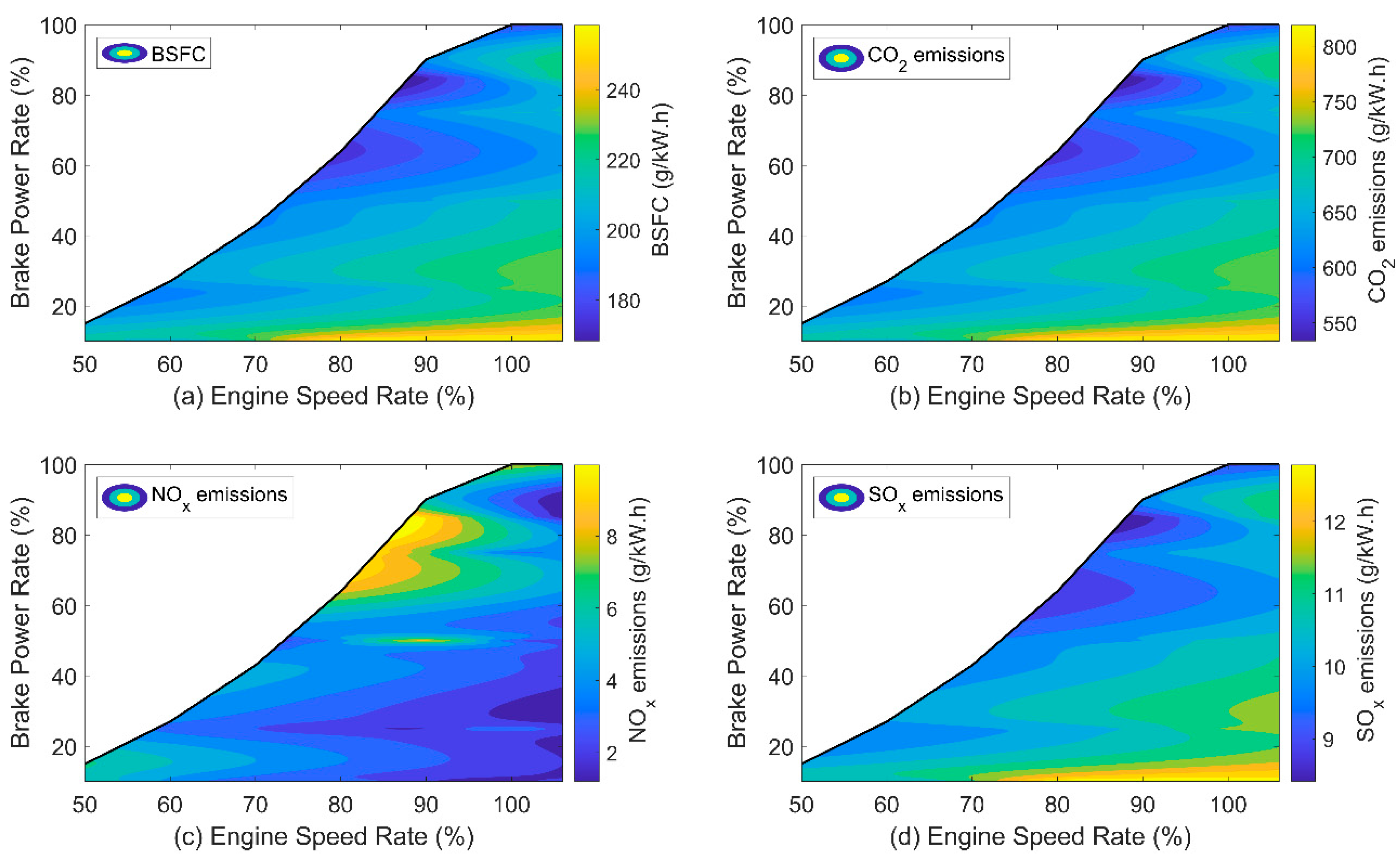
Figure 3.
Load diagram of marine diesel engine. (a) BSFC (b) CO2 emissions (c) NOx emissions (d) SOx emissions [38,46].


Table 1.
Container ship data.
| Item | Unit | Value |
|---|---|---|
| Waterline Length | m | 111.18 |
| Breadth | m | 19.50 |
| Draft | m | 7.239 |
| Displacement | tonne | 11166 |
| Deadweight | tonne | 7650 |
| Block coefficient | - | 0.694 |
| Design speed at 85% MCR | knots | 18.3 |
| Number of propellers | - | 1 |
Table 2.
Main engine specifications.
| Parameter | Unit | Value |
|---|---|---|
| Bore | mm | 320 |
| Stroke | mm | 440 |
| No. of cylinders | - | 18 |
| Displacement | liter | 640 |
| Number of valves per cylinder | - | 4 |
| Compression ratio | - | 17.3:1 |
| BMEP | bar | 23.06 |
| Piston speed | m/s | 11 |
| Engine speed | rpm | 750 |
| BSFC | g/kW/h | 179 |
| Power-to-weight ratio | kW/kg | 0.095 |
Table 3.
Propellers optimized for a ship speed of 17 knots.
| Propeller Characteristics | Gearbox Characteristics | Engine Operating Conditions | Fuel Consumption | |||||||||||
|---|---|---|---|---|---|---|---|---|---|---|---|---|---|---|
| n° of Blades | Thrust | Speed | Torque | D | EAR | Pitch | P/D | ηo | GBR | Speed | Brake Power | Loading Ratio | BSFC | |
| # | [kN] | [rpm] | [kN·m] | [m] | [-] | [m] | [-] | [-] | [-] | [rpm] | [kW] | [%] | [g/kW/h] | [kg/nm] |
| 3 | 536 | 116 | 430 | 5.26 | 0.632 | 4.946 | 0.940 | 0.622 | 5.96 | 692 | 5509 | 60.0 | 191 | 62.0 |
| 4 | 536 | 96 | 511 | 5.39 | 0.811 | 6.017 | 1.116 | 0.629 | 7.15 | 687 | 5509 | 60.0 | 191 | 61.8 |
| 5 | 536 | 105 | 468 | 5.17 | 0.929 | 5.52 | 1.067 | 0.633 | 6.45 | 678 | 5509 | 60.0 | 190 | 61.5 |
| 6 | 536 | 108 | 460 | 5.07 | 0.636 | 5.322 | 1.050 | 0.627 | 6.41 | 693 | 5473 | 59.6 | 192 | 61.7 |
Table 4.
Propellers optimized for a ship speed of 18 knots.
| Propeller Characteristics | Gearbox Characteristics | Engine Operating Conditions | Fuel Consumption | |||||||||||
|---|---|---|---|---|---|---|---|---|---|---|---|---|---|---|
| n° of Blades | Thrust | Speed | Torque | D | EAR | Pitch | P/D | ηo | GBR | Speed | Brake Power | Loading Ratio | BSFC | |
| # | [kN] | [rpm] | [kN·m] | [m] | [-] | [m] | [-] | [-] | [-] | [rpm] | [kW] | [%] | [g/kW/h] | [kg/nm] |
| 3 | 675 | 115 | 576 | 5.52 | 0.541 | 5.358 | 0.971 | 0.624 | 6.42 | 739 | 7298 | 79.5 | 198 | 80.3 |
| 4 | 675 | 111 | 595 | 5.47 | 0.685 | 5.515 | 1.008 | 0.627 | 6.60 | 733 | 7322 | 79.8 | 196 | 79.9 |
| 5 | 675 | 109 | 595 | 5.47 | 0.733 | 5.504 | 1.006 | 0.637 | 6.69 | 730 | 7226 | 78.7 | 198 | 79.3 |
| 6 | 675 | 98 | 654 | 5.63 | 0.733 | 6.04 | 1.074 | 0.644 | 7.43 | 728 | 7153 | 77.9 | 199 | 79.1 |
Table 5.
Projected fuel consumption on the main transatlantic routes.
| Route | Length | % North Atlantic Trades | Fuel Consumption [t] | |
|---|---|---|---|---|
| [nm] | 17 kn | 18 kn | ||
| English Channel–Gulf of Mexico (South) | 3210 | 22.6 | 197 | 255 |
| English Channel–Gulf of Mexico (North) | 3253 | 13.9 | 200 | 258 |
| English Channel–Virginia | 2029 | 13.7 | 125 | 161 |
| Strait of Gibraltar–Virginia (North) | 1958 | 11.3 | 120 | 155 |
| Strait of Gibraltar–Virginia (South) | 2762 | 12.1 | 170 | 219 |
| Strait of Gibraltar–Miami | 3048 | 9.8 | 187 | 242 |
Publisher’s Note: MDPI stays neutral with regard to jurisdictional claims in published maps and institutional affiliations. |
© 2021 by the authors. Licensee MDPI, Basel, Switzerland. This article is an open access article distributed under the terms and conditions of the Creative Commons Attribution (CC BY) license (http://creativecommons.org/licenses/by/4.0/).
Share and Cite
MDPI and ACS Style
Tadros, M.; Vettor, R.; Ventura, M.; Guedes Soares, C. Coupled Engine-Propeller Selection Procedure to Minimize Fuel Consumption at a Specified Speed. J. Mar. Sci. Eng. 2021, 9, 59. https://doi.org/10.3390/jmse9010059
AMA Style
Tadros M, Vettor R, Ventura M, Guedes Soares C. Coupled Engine-Propeller Selection Procedure to Minimize Fuel Consumption at a Specified Speed. Journal of Marine Science and Engineering. 2021; 9(1):59. https://doi.org/10.3390/jmse9010059
Chicago/Turabian StyleTadros, Mina, Roberto Vettor, Manuel Ventura, and Carlos Guedes Soares. 2021. "Coupled Engine-Propeller Selection Procedure to Minimize Fuel Consumption at a Specified Speed" Journal of Marine Science and Engineering 9, no. 1: 59. https://doi.org/10.3390/jmse9010059
Note that from the first issue of 2016, this journal uses article numbers instead of page numbers. See further details here.