Vessel Multi-Parametric Collision Avoidance Decision Model: Fuzzy Approach


1
Faculty of Maritime Studies and Transport, University of Ljubljana, 6320 Portoroz, Slovenia
2
Faculty of Navigation, Maritime University of Szczecin, 70-500 Szczecin, Poland
*
Author to whom correspondence should be addressed.
J. Mar. Sci. Eng. 2021, 9(1), 49; https://doi.org/10.3390/jmse9010049
Submission received: 10 December 2020
/
Revised: 24 December 2020
/
Accepted: 2 January 2021
/
Published: 5 January 2021
(This article belongs to the Special Issue Advances in Navigability and Mooring)
Abstract
:The application of fuzzy logic is an effective approach to a variety of circumstances, including solutions to maritime anti-collision problems. The article presents an upgrade of the radar navigation system, in particular, its collision avoidance planning tool, using a decision model that combines dynamic parameters into one decision—the collision avoidance course. In this paper, a multi-parametric decision model based on fuzzy logic is proposed. The model calculates course alteration in a collision avoidance situation. First, the model collects input data of the target vessel and assesses the collision risk. Using time delay, four parameters are calculated for further processing as input variables for a fuzzy inference system. Then, the fuzzy logic method is used to calculate the course alteration, which considers the vessel’s safety domain and International Regulations for Preventing Collisions at Sea (COLREGs). The special feature of the decision model is its tuning with the results of the database of correct solutions obtained with the manual radar plotting method. The validation was carried out with six selected cases simulating encounters with the target vessel in the open sea from different angles and at any visibility. The results of the case studies have shown that the decision model computes well in situations where the own vessel is in a give-way position. In addition, the model provides good results in situations when the target vessel violates COLREG rules. The collision avoidance planning tool can be automated and serve as a basis for further implementation of a model that considers the manoeuvrability of the vessels, weather conditions, and multi-vessel encounter situations.
1. Introduction
Decision-making and responsiveness are the navigator’s primary activities in avoiding collisions at sea. Due to the reduced number of the crew on the bridge, the amount of information required per person has increased, which adds a burden to the decision-making process. The decision is also influenced by the traffic situation, weather conditions, and, finally, the navigator’s experience. Vessel avoidance has additional peculiarity as the navigator has extensive knowledge of his vessel and limited information of the vessels in the vicinity, which means that he/she makes decisions in an uncertain environment [1]. The automation of navigation devices has brought a new approach to maritime safety in maritime affairs and, at the same time, changed the nature of human error [2]. An essential cognitive aspect of the problem of automation is: How does the human brain process certain information? How much data is a person able to receive at one time? How should the information be displayed so that a person can receive it in the correct form and use it for further decision-making?
The improvement of maritime safety in the 1970s was mainly due to the upgrade of navigation radar with the Automatic Radar Plotting Aid (ARPA), a support decision-making tool for collision avoidance at sea. Above all, it shortened the time of collision risk assessment and increased the navigator’s situation awareness. Although ARPA contains a lot of information about vessels in the area and a Trial Manoeuvre tool to simulate collision avoidance using a time delay command, there are standard limitations and errors that radars have, especially regarding the processing time of the received signal [3]. According to the International Maritime Organization (IMO) requirements, the ARPA radar must display, in one minute and with 95% accuracy, the relative motion (relative course and speed) and DCPA (Distance to Closest Point of Approach) of the target vessel; within three minutes, record the overall trend of the target vessel—relative and true course, relative and true speed, DCPA, and TCPA (Time to Closest Point of Approach). Therefore, it is advisable to use these data from the Automatic Identification System (AIS) device since they are updated, on average, every 30 s (depending on the vessels’ speed and course change). Both ARPA radar and AIS are currently integrated into the Electronic Chart Display and Information System (ECDIS) and the navigator has a lot of information available on a single screen. However, the Trial Manoeuvre tool for planning collision avoidance at sea still requires manual adjustments which, in turn, means extending decision-making time in a situation that requires a dynamic decision-making process. There are also no integrated COLREG rules in the system itself, and their application is left to the knowledge of the person steering the vessel.
To relieve the navigator of the glut of information of today’s technology used onboard vessels, in 2009, IMO issued a Strategy for the Development and Implementation of E-Navigation (MSC85-Report, Annexes 20 and 21). The goal of E-Navigation development is to improve maritime safety by integrating existing and new navigation devices in a structured manner, simplifying processes to prevent information overload and increase safety by aggregating information into those which are genuinely relevant for the navigator [4]. The task of the navigation decision system, besides its information function, is to supply solutions—determination of safe vessel trajectories in the process of collision avoidance. Decision systems consist of several components, including components for collision risk assessment and avoidance manoeuvre calculation. Quantitative methods of calculating the collision risk could primarily include the calculation of the CPA point. As it represents the distance to the closest point of approach, it is the first indicator of the possibility of a collision or entry into the area of the safe vessel’s domain. A vessel’s safety domain is the sea area around the vessel, which must remain free from other vessels and fixed installations. In some ARPA radars, the PAD method (Predicted Area of Danger) can also be found to show the collision estimate, which, unlike the CPA method, also takes into account the dimensions of both vessels, course, and speed [5,6]. Most of the early vessel’s safety domain developments were created by statistical and analytical methods, and oval and elliptical shapes predominated. In recent times, however, we find models that change dynamically according to different navigation situations: vessel size, traffic density, relative speed, type of navigation situation, weather conditions, visibility, etc. [7,8]. According to Cockcroft [9], the size of a vessel’s domain cannot be quantified, but it is suggested that in degraded visibility, this is limited to 2 M. However, it may be lower at low speeds in heavy traffic, in an overtaking situation, or when the observed vessel is expected to sail aft. In practice, this area is determined subjectively by the navigator, or it is determined by the shipowner or another person/institution responsible for it. If there is a risk that another vessel will enter the vessel’s domain, an appropriate collision avoidance manoeuvre is required in accordance with the COLREG rules.
Many researchers are engaged in the development of the collision avoidance systems. Models of research may be divided into three main categories: mathematical models and algorithms, soft computing (the evolutionary algorithms, neural networks, fuzzy logic, and expert systems), and a combination of all—a hybrid navigation system [10]. The decision model, which determines the appropriate collision avoidance manoeuvre based on fuzzy logic, was introduced by several authors, among them Perera [6], who primarily shed light on situations occurring on the high seas when a vessel is in a critical position in relation to another vessel and must perform the collision avoidance manoeuvre. The simulation was tested using MATLAB’s Fuzzy Logic Toolbox using the Mamdani fuzzy inference system. In setting rules (144 rules in total), the author specified five input parameters: the region where the target vessel is located; the relative course of the target; the level of encounter risk; the distance to the target, and the relative speed of approach. Based on these parameters, the model decided on the need to change course or speed based on COLREG rules 13, 14, and 15. In the following article [11], they tried to solve the problem of avoiding multiple vessels by combining fuzzy logic and the graphical probability model—Bayesian networks. Later, fewer input parameters were used to find the appropriate avoidance manoeuvre for the fuzzy inference system: distance to the target vessel, azimuth, relative course, and speed of approach [12]. Selection of the navigation strategy in traffic separation scheme, using a decision model based on a fuzzy logic algorithm was proposed by Wu [13], who analysed the dynamic characteristics of the navigation process. With a similar fuzzy logic approach the risk of collision with static and moving objects was calculated [14,15]. Zhuo et al. [16] calculated, in their model, the start time of the manoeuvre by altering the course by 30° in relation to the target vessel at 0.8 nautical miles (M). A similar approach to collision avoidance was taken by Su et al. [17] who calculated the position of own vessel to initiate avoidance for different rudder deviations. An attempt to find the optimal avoidance path was presented by Pietrzykowski [18], where an optimal control method was used for vessel motion: a multi-stage fuzzy control in combination with the Dijkstra algorithm for determining the shortest path. Using a combination of fuzzy logic and neural networks, Liu [19] calculated the direction and magnitude of own vessel course change and the time at which the alteration began. In doing so, they used input parameters with different navigation situations (COLREG rules 13, 14, and 15) and the speed ratio between the own and the target vessel. The vessel’s trajectory in collision avoidance situations was also the basis for research by Szłapczyński [20], who used the technique of evolutionary algorithms that allow the navigator to predict the trajectory of the target vessel and thus plan its manoeuvre. In a congested traffic area, this method would also allow the VTS (Vessel Traffic System) operator to coordinate the movements of all vessels. More complex hybrid systems for autonomous navigation were presented by Lee et al. [21] and Hu [22]. They, in addition to using fuzzy logic, also introduced a Virtual Force Field (VFF) known in the field of mobile robotics.
In this paper, a collision avoidance decision model is proposed, based on fuzzy logic which calculates course alteration using four parameters. The model is considered as an upgrade of the current Trial Manoeuvre tool in ARPA radar, which is used to plan collision avoidance manoeuvres. The model structure and the rule-based system are built using a database of correct solutions, obtained by manual radar plotting method. This presents a novel approach in determining fuzzy parameters and rules. Additionally, two important segments of collision avoidance are considered in the model:
- the direction of avoidance (in compliance with COLREG rules 8 and 19), and
- the minimum course alteration (in compliance with COLREG rule 8).
The quality of the execution of the avoidance manoeuvre is, thus, not only in achieving a safe distance for the passage of vessels but also in the process of manoeuvring.
The paper is structured as follows. Section 2 provides a brief introduction to the methodology of fuzzy logic; Section 3 describes the design of the decision model in a two-step sequence, which also represents the originality of this study. Each step is described in more detail in sub-sections defining input parameters, the fuzzy inference system with its fuzzy rules and the output decision of the decision model. Section 3 presents six selected case studies that simulate different navigation situation encounters. In Section 4, the presented case studies are discussed, followed by the conclusion.
2. Fuzzy Logic Methodology
The literature review presented several methods for calculating the collision avoidance manoeuvre. The proposed decision model uses fuzzy logic, which belongs to the techniques of artificial intelligence. The advantage of fuzzy logic is that decisions can be made based on inaccurate data that cannot be described in mathematical notation because they are expressed in words. Zadeh [23] justified the numerical methods of fuzzy logic by claiming that humans perceive events in their environment inaccurately and without a precise distribution law. Fuzzy logic thus imitates the human way of thinking, which can solve complex tasks, although they may also contain a great deal of uncertainty. Other advantages to using fuzzy logic for a decision model are its ease of use and transparency, which were two essential features when choosing this technique. Fuzzy computing has also proven to be a very widespread technique in other areas of transport; some such examples were cited by Teodorović [24]: solving the problem of vehicle routing, route selection or timetable optimisation in various transport industries, regulation of traffic lights, etc.
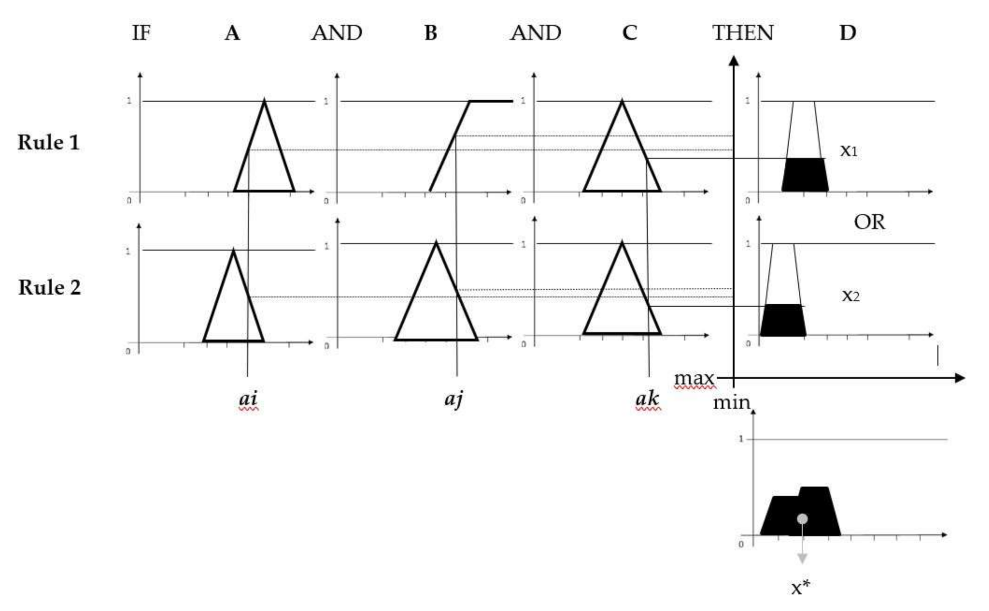
Fuzzy inference system (FIS) is the process of formulating the mapping from a given input to output using fuzzy logic. It is one of the main elements of the fuzzy logic system. The FIS type in this paper is “Mamdani”. The use of the IF-THEN rules is organised with the “AND (min)” and “OR (max)” operators. Therefore, the basic tasks of the fuzzy inference system (FIS) are fuzzification, fuzzy reasoning and defuzzification. Fuzzification is a procedure in which the input data is placed in an appropriate set, which is at the same time a linguistic variable, and the grade of membership is determined. The mathematical logic theory assumes only correct and incorrect statements; in fuzzy logic, however, an element belongs to a set with a certain grade of membership (µx). Fuzzy sets have different shapes; in the literature, triangular and trapezoidal are commonly used, represented by mathematical notation:
![Jmse 09 00049 i001]()
![Jmse 09 00049 i002]()
![Jmse 09 00049 i003]()
![Jmse 09 00049 i004]()


Fuzzy reasoning or the process of mapping input data to output decision is performed with a base of rules formed by IF–THEN conditional statements. Defuzzification is the last step in FIS and is a conversion of fuzzy output quantities into a crisp output quantity. For each unit of input and output data, a degree of membership in the corresponding fuzzy set is assigned. A common mapping is multiple inputs to one output, but there can also be multiple outputs. The greater their number, the greater the number of fuzzy rules in the system which, unfortunately, also affects its transparency. The decision model uses the Mamdani fuzzy inference type. A characteristic of this type is that both inputs and outputs are interpreted with linguistic variables connected by the fuzzy operators “min” and “max”. The value of a linguistic variable is also called fuzzy value, which describes belonging to a certain fuzzy set [25]. Fuzzy logical operators are defined as follows:
- AND (“min”)—fuzzy cross section or conjunction,
- OR (“max”)—fuzzy union or disjunction,
- NOT—fuzzy complement.
The membership function of the output data D has a form (Figure 1):
which means that the input data are combined with the “min” function:
and the output data is combined with the “max” function:
The latter calculates the sum of all outputs, thus obtaining a shape representing a fuzzy set of all output data. A commonly used data sharpening method is the “centre of gravity” method, which is calculated by
The input parameters and the output decision, the composition of the fuzzy membership functions for each input and output, and the fuzzy rules that perform the process of fuzzy reasoning are presented in the following sections.
3. Design of the Proposed Collision Avoidance Model
Avoidance manoeuvre is a process that requires planning and observation of dynamic navigation situations in an appropriate timeframe. Vessel movement prediction is an important part of planning, with extrapolation of the vessel’s trajectory within a time delay. As on the radar, the navigation situation in the model is presented from the own vessel perspective. The observed vessel is considered as target vessel. The proposed decision model calculates the decision using two steps. In step one, the model collects input data of own and target vessels to assess the collision risk. To predict the target vessel position at the time of collision avoidance manoeuvre, time delay calculation is used to obtain the new relative position of a target vessel. At this point four parameters are calculated for further processing as input variables in a fuzzy inference system. The second step is calculation of the decision (course alteration), using fuzzy logic methodology.
3.1. FIS Input Parameters Calculation
In this paper the calculation of the appropriate course alteration is influenced by four dynamic parameters as input variables of the FIS:
- DCPA—Distance to Closest Point of Approach,
- AP—Action Point distance to the target vessel,
- RB—Relative Bearing of a target vessel,
- Vo—Own vessel Velocity.
To calculate input parameters used in a fuzzy inference system, the predicted position of a target vessel is calculated using a time delay [27]. A time delay of the navigation situation is a set of functions that calculate the relative position of the target vessel for the desired time delay if the course and speed of own and target vessel do not change in time. This method is called “Static Calculation of a Trial Manoeuvre”. The new relative position of the target vessel is calculated as follows:
where dtN is the new distance to target vessel, XtN is the new relative position coordinate of the target vessel, ωtN is a new azimuth of a target vessel, and RB is a new relative bearing of the target vessel.
RB = ωt − Co [°],
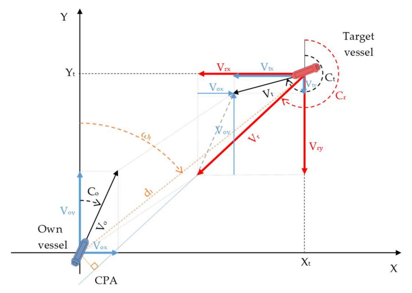
Collision risk assessment parameters DCPA and TCPA are calculated with the following [28]:
where Xt and Yt are relative position coordinates of the target vessel, Vrx and Vry are relative velocity vector components, and Vr is the relative velocity of the approach (Figure 2).
The AP and RB parameters are time variables, DCPA and V are considered as static data (assuming both vessels keep speed and course). Since fuzzy reasoning is conditioned by uncertainty, the velocity of the target vessel, relative velocity of the approach, and TCPA of the target vessel were not used as input parameters when modelling the fuzzy inference system since the consideration of the AP parameter nullifies the influence of these variables.
According to fuzzy logic theory, a parameter must be assigned to an appropriate fuzzy set. In the following sub-sections, parameters are presented in detail, and for each value, a degree of membership in the corresponding fuzzy set is assigned.
3.1.1. DCPA Parameter
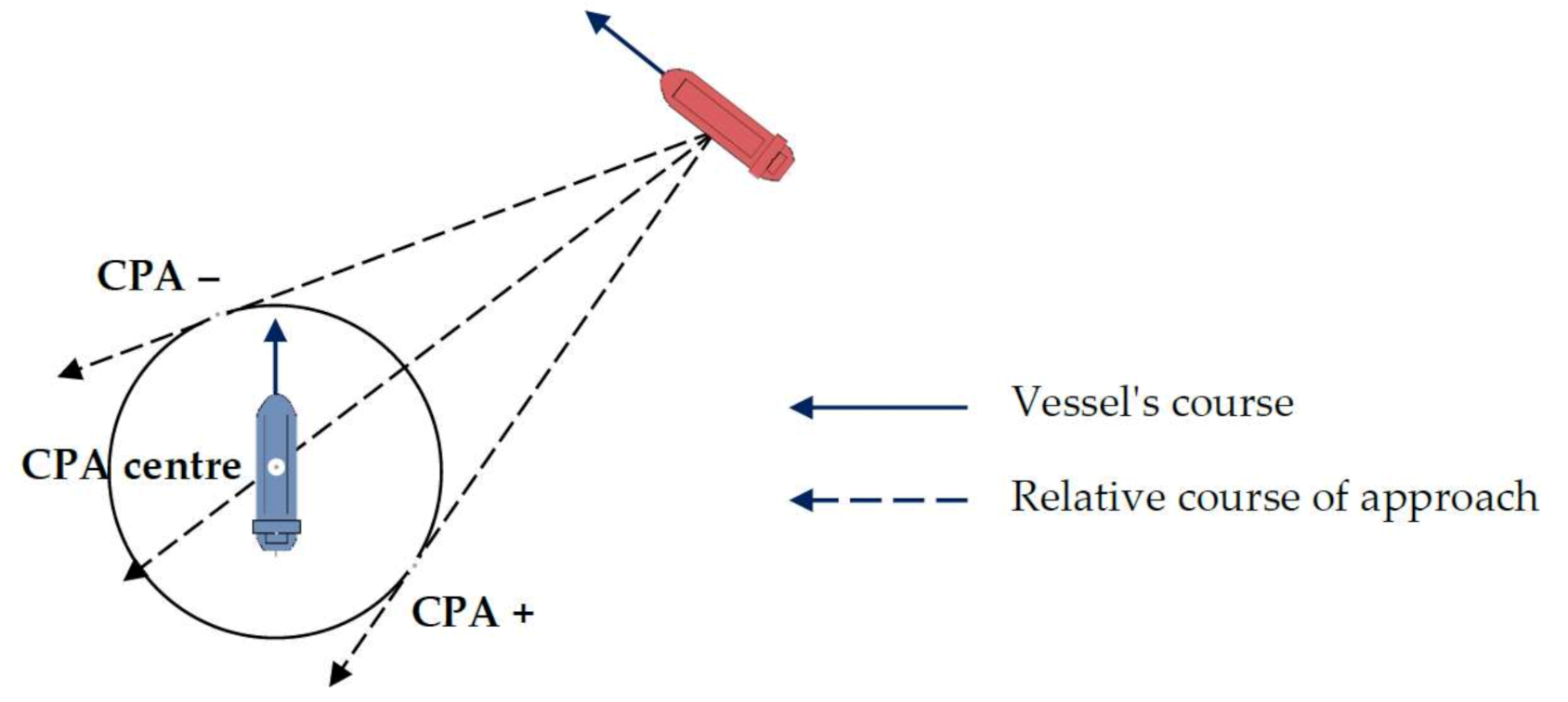
DCPA is a dynamic parameter. If its value is lesser than a predetermined safe vessel domain, there is a risk of collision with the target vessel or object. Of particular importance is the position of the CPA (Closest Point of Approach), whether the own vessel will encounter the target vessel from the starboard side, port side, or through the centre [26].
The position of the CPA affects the size of the course alteration. Different directions of approach require a different course alteration; a larger alteration is already noticeable with the difference of the DCPA value +/− 0.3 M. Three trapezoidal membership functions were created for the DCPA parameter: negative, centre, and positive. Since DCPA data obtained from navigational devices do not provide information about the position of the CPA relative to own vessel (Figure 3), the positive or negative value of the DCPA is determined according to the following rule: if azimuth of the target vessel increases with time (time of observation), the position of the CPA is “positive” and the DCPA parameter has a positive value; if the azimuth of the target ship decreases with time, the CPA position is “negative” and the DCPA parameter has a negative value.
The following equations represent the DCPA membership functions:
These values were chosen since direct collisions are represented by values in the interval of −0.3 and +0.3 M, with a degree of membership equal to 1; for other values up to −0.5 or +0.5, the degree of membership decreases or increases linearly. The trapezoidal shape of a membership function was chosen because several elements in the individual fuzzy set represent the core of the membership function, i.e., grade of membership in the fuzzy set equals 1. This also applies to fuzzy sets for other parameters.
3.1.2. Action Point Parameter
This parameter is a calculated new distance to the target vessel using time delay simulation in step 2 (dtN). According to Cockcroft [9], there are four stages of a close-quarters situation: from the moment when there is no risk of collision (stage one) to the extreme situation when the stand-on vessel is required to take action to avoid collision (stage four). Intermediate stages are collision avoidance by give-way vessel (stage two) on a safe passing distance to the stand-on vessel, which is 5 to 8 M on the open sea. This numbers are also related to visibility of ship lights on open sea according to COLREGs [29]; and collision avoidance by stand-on vessel, at the maximum distance 2 to 3 M from the give-way vessel [9]. Some shipowners are very specific in determining the AP. The CMA CGM safety management system sets the distance 6 M for the navigational situations covered by COLREG regulations 14 and 15 [30]. In the case of overtaking, the minimum distance to the observed vessel must be 2 M.
Based on the proposed distances in the literature, three trapezoidal membership functions were formed describing the distance to the target vessel the moment the own vessel starts the avoidance manoeuvre:
- Near—covers the area from >0 to 5 M distance, with varying degrees of membership,
- Middle—this area covers a distance between 2.5 and 9 M, with varying degrees of membership,
- Far—is a fuzzy set for all distances above 6 M taking values between 6 and 7.5 M with varying degrees of membership.
3.1.3. Relative Bearing Parameter
In the decision model, RB is measured in a clockwise direction, 0–360°. In practice, an angle of the approaching vessel is rarely expressed in degrees and, rather, in words according to general directions onboard (bow, stern, portside, starboard side). Therefore, the RB as an input parameter of the fuzzy inference system consisting of 8 fuzzy sets with corresponding trapezoidal membership functions, which are described by the words: Starboard Bow, Starboard Bow/Beam, Starboard Beam, Starboard Quarter, Stern, Port Quarter, Port Beam and Port Bow. The following values were adjusted during simulations until they took the following forms:
3.1.4. Velocity Parameter
An important parameter that influences the degree of the course alteration is own vessel’s speed (velocity). The lower it is, the greater the alteration of the course is required for vessels to meet the safe distance. The velocity parameter consists of three fuzzy sets with corresponding trapezoidal membership functions:
- Low,
- Normal,
- High.
The fuzzy sets were defined according to a database of correct solutions, where three different own vessel’s velocities were used: 10, 15, and 20 kn. In the fuzzy set “Low”, vessels with speeds up to 12 kn were included, such as fishing boats, vessels approaching harbours, pilot stations, etc. The fuzzy set “Normal” includes vessels with speeds between 8 and 16 kn, which is normally the half ahead or full ahead speed of an average bulk carrier. “High” includes vessels with speed higher than 16 kn: high speed boats, container ships, etc. The following values were adjusted during simulations until they took the following forms:
3.2. Decision Calculation
The most common way of collision avoidance is the alteration of the course. Such a manoeuvre is also the most appropriate, as COLREG rule 8 dictates:
“(b) Any alteration of course and/or speed to avoid collision shall, if the circumstances of the case admit, be large enough to be readily apparent to another vessel observing visually or by radar; a succession of small alterations of course and/or speed should be avoided”.[29]
From the interpretation of rule 8, it can be concluded that the manoeuvre must be noticeable, which is not the case if the speed is reduced by a few knots. In addition, the uncertainty of a navigator who observes such a manoeuvre from another vessel can trigger wrong decisions. Cockcroft [9] recommends that the course alteration should be at least 30°, but it is a better recommendation that the course be changed in the range of 60 to 90°. Depending on the position of the target vessel, the course alteration can be made to the port or starboard side.
The output of the decision model is the alteration of own vessel course in degrees to the port or starboard side, which is used to calculate the trajectory of the vessel in the process of Trial Manoeuvre. It is described by nine fuzzy sets with words used in maritime communication:
- Steady,
- Easy to Stbd/Port,
- Mid to Stbd/Port,
- Hard to Stbd/Port,
- Full to Stbd,
- Full Turn.
Fuzzy sets were determined subjectively by authors.
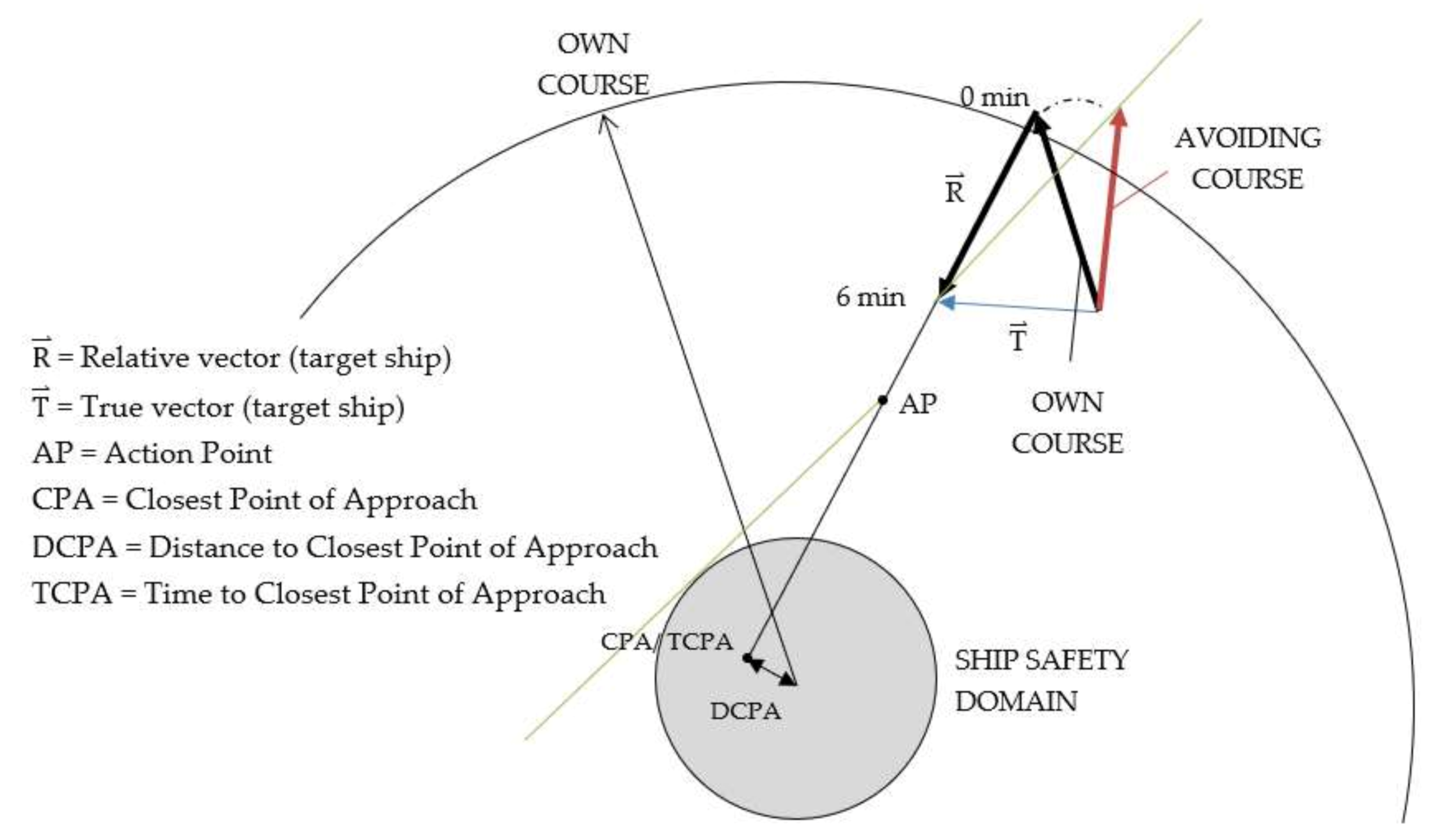
The process of mapping the input parameters into the output decision is regulated by a system of fuzzy rules. Rules were created by observing the results of the database of correct solutions and the interpretation of COLREG rules 8 and 19. A database of correct solutions was created by the traditional method of calculating alteration of course, the manual radar plotting method. Manual radar plotting (Figure 4) is a method in which the azimuth and range of a signal are measured on a radar screen at time intervals, and the position of the signal is plotted on a manoeuvring board. By connecting the two points of the observed signal, the relative and true vector of the signal movement (or of the vessel) and the CPA point are obtained, which provides essential data for collision risk assessment, DCPA, and TCPA. By planning a new relative trajectory (considering a desired safety domain) of the target vessel, the resolution of the vector triangle determines the collision avoidance course (or speed change) and action point. This method assumes that the target vessel maintains its current course and speed. Database of correct solutions contains 972 decisions (course alteration) at different parameters:
- Distance to closest point of approach of the target vessel (0 M, +0.5 M, −0.5 M),
- Relative bearing of the target vessel (0–350°),
- Action point distance (2, 4, and 6 M),
- Own vessel’s velocity (10, 15, and 20 kn).
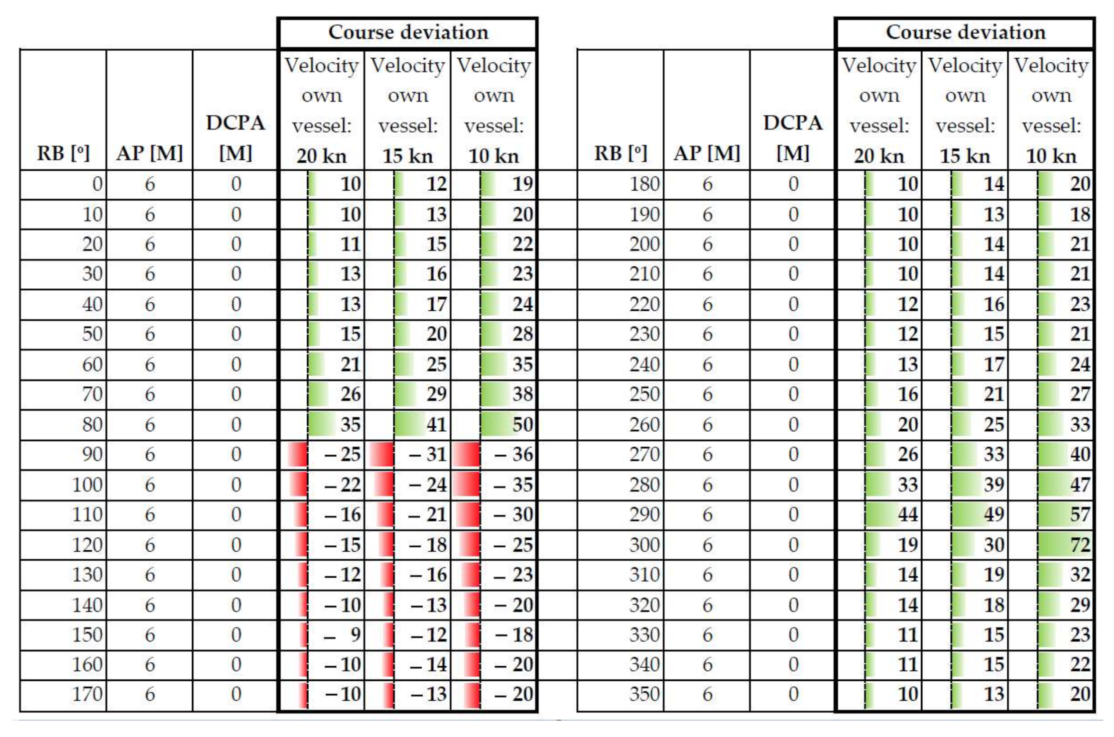
The safety domain for all decisions is 1 M; the relative velocity of approaching in all situations is 20 kn. Both values were chosen subjectively by the authors. COLREG rules 8 and 19 were implemented in the decisions. Figure 5 shows an excerpt from the database of correct solutions for the conditions: DCPA of the target vessel is 0 M, action point distance to target vessel is 6 M at the different relative bearing of an approaching target vessel. The decision is a course alteration for the three different velocities of each vessel.
3.3. Decisions Validation
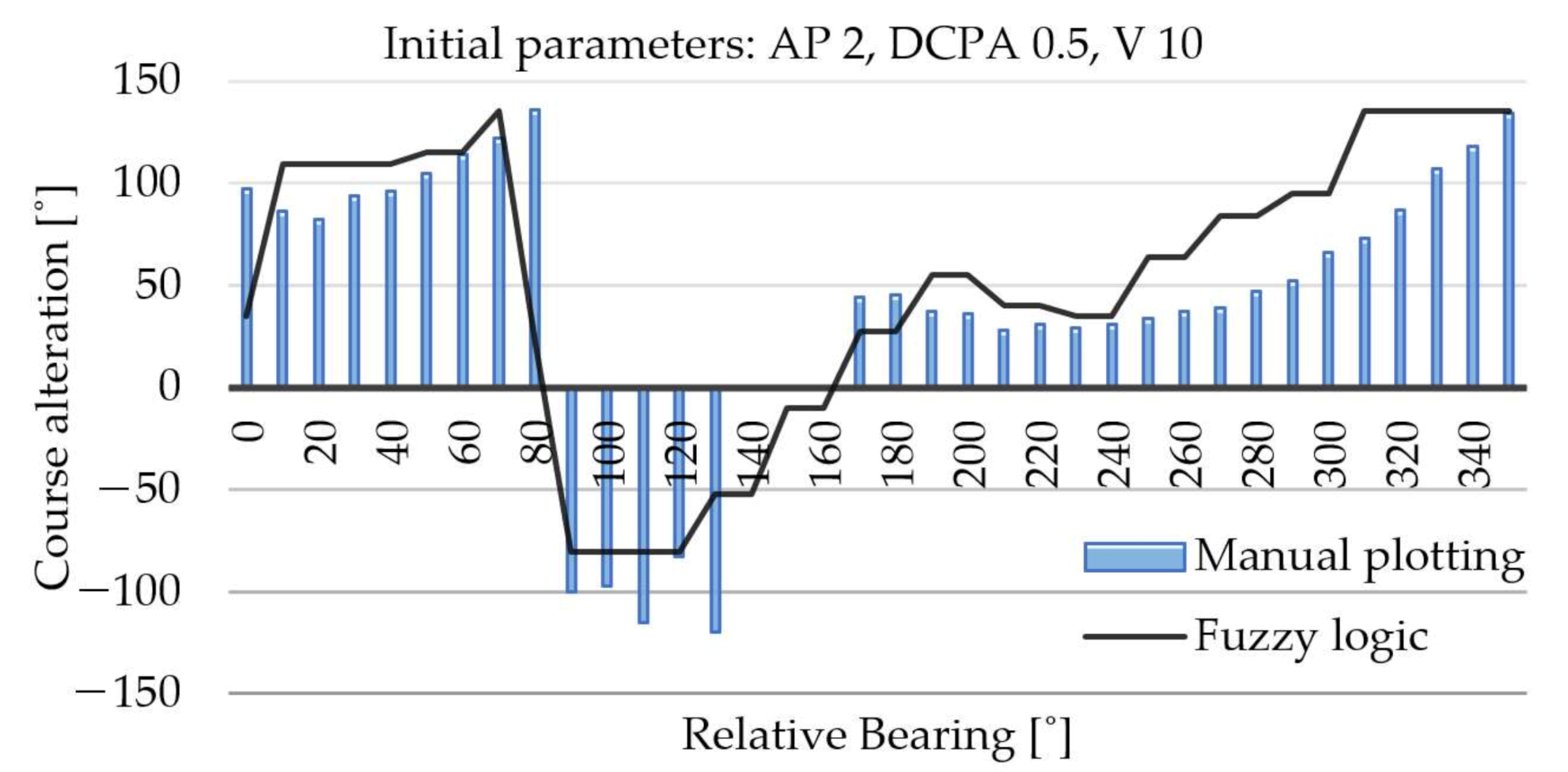
The decision model was tuned until the results of the fuzzy logic outlined a similar area under the curve to the results of the database of correct solutions (Figure 6). Full coverage of graphs was not expected, since fuzzy logic simulates the human way of reasoning, but it was important to match the results in the RB range from 0 to 110°, due to the rule of right (own vessel status: Underway using the engine). Figure 6 shows the results of both methods. The fuzzy logic graph covers almost the entire surface of the manual plotting graph, with minor deviations in individual RB areas.
The composition of the fuzzy rules was based on the principle of finding the maximum value of the “course alteration” for individual areas (in the range of 30 to 40 degrees) of the relative bearing. A total of 216 rules form IF–THEN statements (Table 1).
The fuzzy inference system showed some shortcomings in areas where decisions change from positive to negative, and vice versa, as a result of COLREG rule 19, which dictates that the vessel which detects by radar alone the presence of another vessel shall avoid alteration of course towards the target vessel abeam or abaft the beam. Consequently, the coverage of the graphs in these parts is poorer. This coverage was slightly improved with the additional fuzzy set of the RB parameter »Starboard Bow/Beam«. A similar problem was addressed by Perera et al. [31], which softened the sharp boundaries between the fuzzy sets that were opposing the decisions by adding fuzzy sets that neutralised the sharp transition between the two opposing decisions.
4. Simulations
The simulations’ aim is to demonstrate the quality of the operation of a multi-parametric collision avoidance decision model. There are countless possible situations of encounters at sea; Perera [6] presented, in his article, simulations of encountering a single vessel from different relative bearings: 63, 30, 106, 1, and 296° at distances between 7 and 14 M. This covered all three navigation situations according to the COLREG rules—crossing, overtaking, and head-on. A similar simulation was presented by Ni [32], using multiple generic algorithms and a linear extension algorithm for trajectory planning for different navigation situations on the open sea, and Nguyen [33], in constrained waters in a multi-encounter vessel situation. Zhuo [16] simulated an encounter with three vessels simultaneously located at relative bearings 50, 325, and 2° in a crossing and head-on situation. A similar situation is simulated by Pietrzykowski [18]. Lee et al. [21] considered crossings from the starboard side direction, concerning its own vessel (approach from the direction of relative bearing 30–50° and 90–140°), from portside direction (approach from the direction of relative bearing 300–330° and 220–270°), and overtaking situation.
Another important aspect of collision avoidance at sea is the vessel’s safety domain. The authors, who solved the problem of avoiding collisions at sea comprehensively, mostly used a simple radar circle in the model for a safety domain: Zhang [34] determined the radius of the 1500 m (0.8 M) circle for the safe ship domain, while Pietrzykowski [35] and Szłapczyński [36] used a 1 M circle in the simulations. Zhuo [16] also considered the dimensions of his own and observed ship in the size of the circle. Some authors used simple ellipses, where the size of the large strip was determined by the length of the ship (2× the length of the ship) and the small strip by the width of the ship, 2–4× the breadth of the ship [33,37]. Many authors did not specifically define domain size in decision models, among them Hwang [38], Perera [6], and Hu [39], or they chose the minimum encounter distance [8,40,41,42]. Based on those findings, the minimum vessel’s safety domain in the presented model is assumed to be 1 nautical mile.
The validation was made using the six selected cases, which simulate encounters with the target vessel on the open sea from different angles in any visibility: head-on, crossing, and overtaking situations and different right of way. Observed criterion simulations are collision avoiding in accordance with COLREG and minimum vessel’s safety domain. Moreover, since the simulations are focused on the vessel’s navigation on the open sea, the influence of the navigational behaviour and environmental impacts (wind and currents) are ignored in the modelling process.
4.1. Application of the Proposed Model, Case Study 1 (Overtaking Encounter)
Following is a detailed explanation of decision model calculation (Table 2, Table 3, Table 4 and Table 5). The simulation tests the fuzzy inference system for the encounter situation with target vessel. This situation is governed by COLREG rule 14, the “Head-on situation”, rule 8 “Action to avoid collision”, and rule 19 “Conduct of vessels in restricted visibility”. Both vessels are power-driven. It is assumed that the target vessel keeps her course and speed.
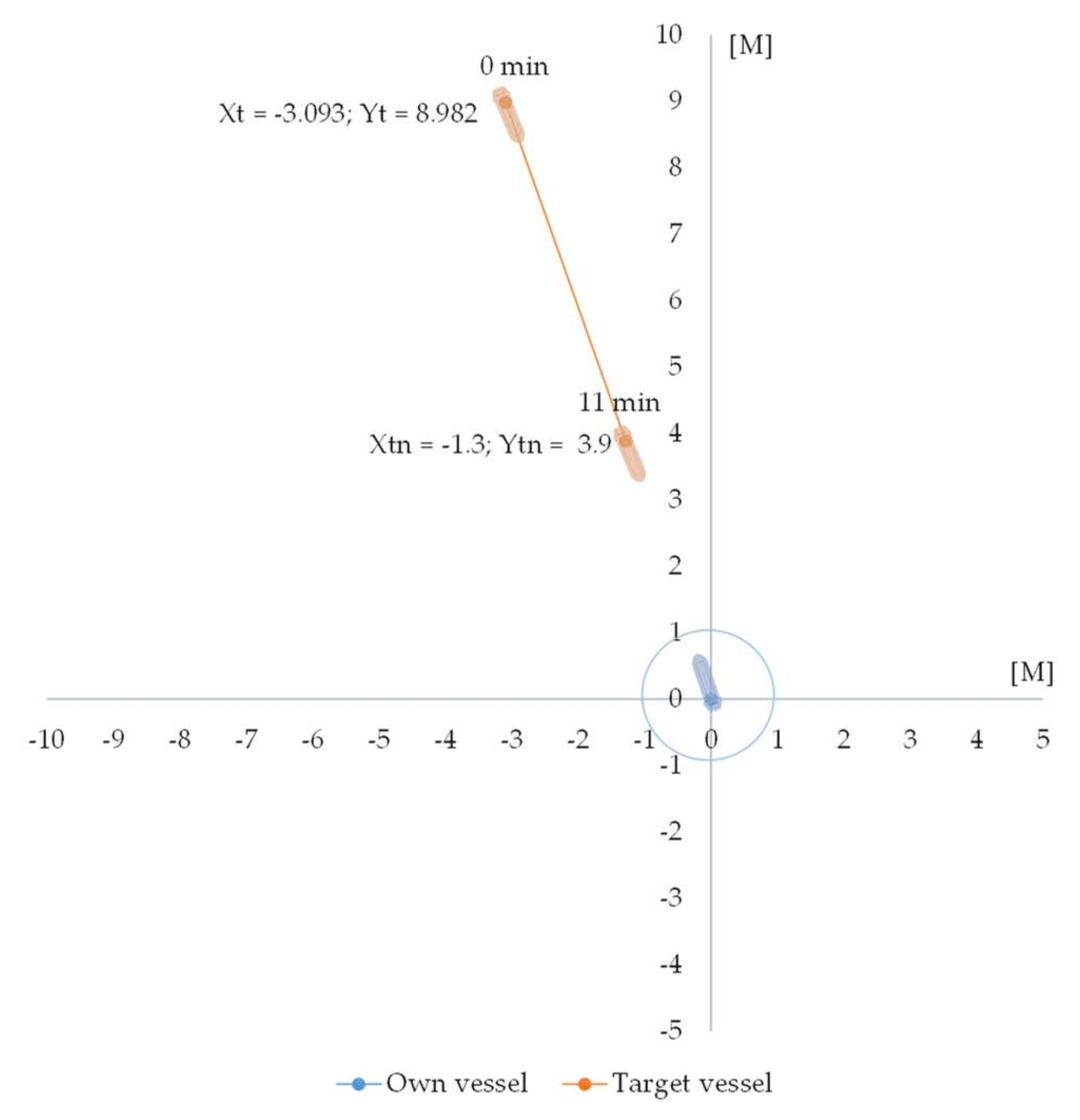
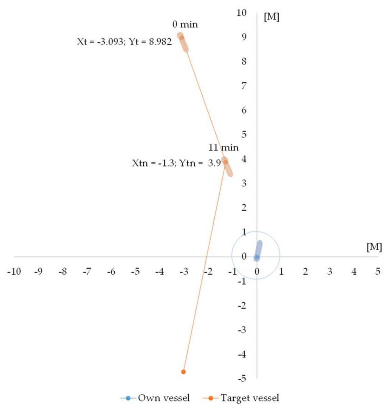
Figure 7 shows a relative movement of the target vessel in a time delay. The next task is to classify the input parameters into fuzzy sets and calculate the grade of membership. This process is called fuzzification:
DCPA = +0.09 M
μCentre(d) = 1, if −0.3 ≤ d ≤ 0.3
Explanation: DCPA +0.09 M belongs to the fuzzy set »Centre« with grade of membership 1.
AP = 4.09 M
μNear(d) = 5 − d, if 4 ≤ d ≤ 5
μNear(d) = 5 − 4.09 = 0.91
μMiddle(d) = 1, if 4 ≤ d ≤ 7.5
Explanation: Distance to target vessel 4.09 M belongs to the fuzzy set »Near«, with grade of membership 0.91, and fuzzy set »Middle«, with grade of membership 1.
RB = 1.739°
μS_Bow(deg) = 1, if deg < 60
Explanation: RB 1.739° belongs to the fuzzy set »Stbd Bow« with grade of membership 1.
V = 16.5 kn
μNormal(V) = 5 − V/4, if 16 ≤ V ≤ 20
μNormal(V) = 5 − 16.5/4 = 0.875
μHigh(V) = 1, if V > 16
Explanation: Own vessel’s velocity 16.5 kn belongs to the fuzzy set »Normal« with grade of membership 0.875 and fuzzy set »High« with grade of membership 1.
The second task is the activation of the FIS based on fuzzy rules (Table 6). Since input parameters AP and V belong to two fuzzy sets, respectively, four fuzzy rules (Rn) are activated:
The following is the calculation of the value of each fuzzy rule output with the intersection of the fuzzy sets DCPA ∩ AP ∩ RB ∩ V:
Rule 1: μD (x1) = min [1, 0.91, 1, 1] = 0.91
Rule 2: μD (x2) = min [1, 0.91, 1, 0.875] = 0.875
Rule 73: μD (x3) = min [1, 1, 1, 1] = 1
Rule 74: μD (x4) = min [1, 1, 1, 0.875] = 0.875
The union of all outputs is
μD (x) = max [μD (x1), μD (x2), …, μD (xn)] = max [0.91, 0.875, 1, 0.875] = 1.
All outputs belong to the fuzzy set »Mid to Stbd«.
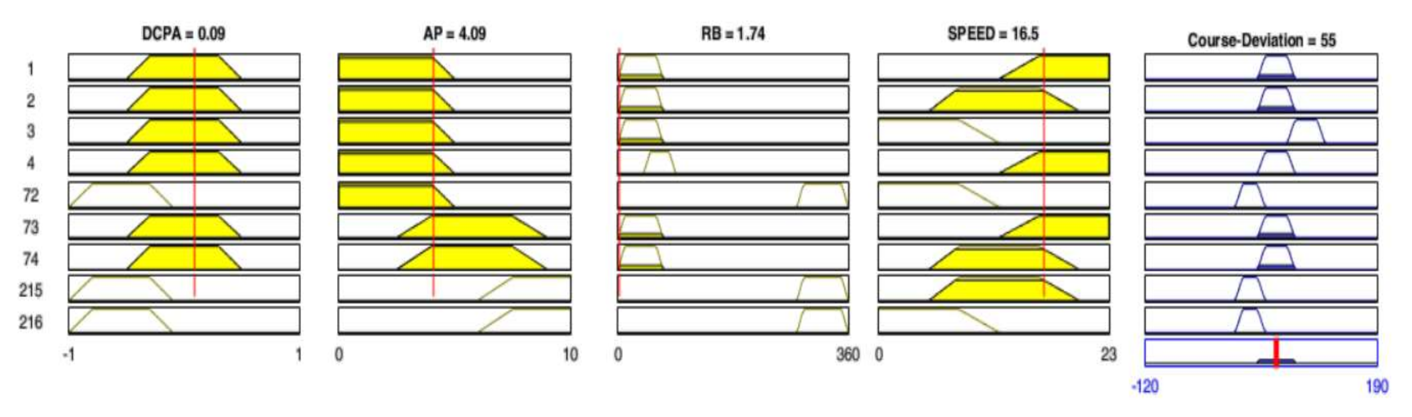
The following is the last task in the process, known as defuzzification. It is a process of calculation of the crisp output, i.e. course alteration. The defuzzification method used is a centroid method. Figure 8 shows excerpt of mapping input data into output decision using MATLAB Fuzzy Logic Toolbox.
Explanation: The decision model calculates course alteration x* = 55°, and the new course for collision avoidance is 35°. Figure 9 shows a relative movement of the target vessel after course alteration.
Analysis: Case study 1 shows an encounter with a target vessel approaching from opposite directions. The decision model assesses the risk of collision by calculating a DCPA value which is less than the safe ship domain of 1 M according to initial data. With a time delay of the navigational situation for 11 min, the model calculates the input parameters of the fuzzy inference system RB and AP. Based on the input parameters, the fuzzy inference system calculates the course alteration and reassess the risk of a collision. The model graphically plots the planned trajectory of the target vessel. The new DCPA of the encounter after course alteration confirms the quality of the calculated avoidance manoeuvre as it is greater than 1 M (Table 7).
4.2. Case Studies
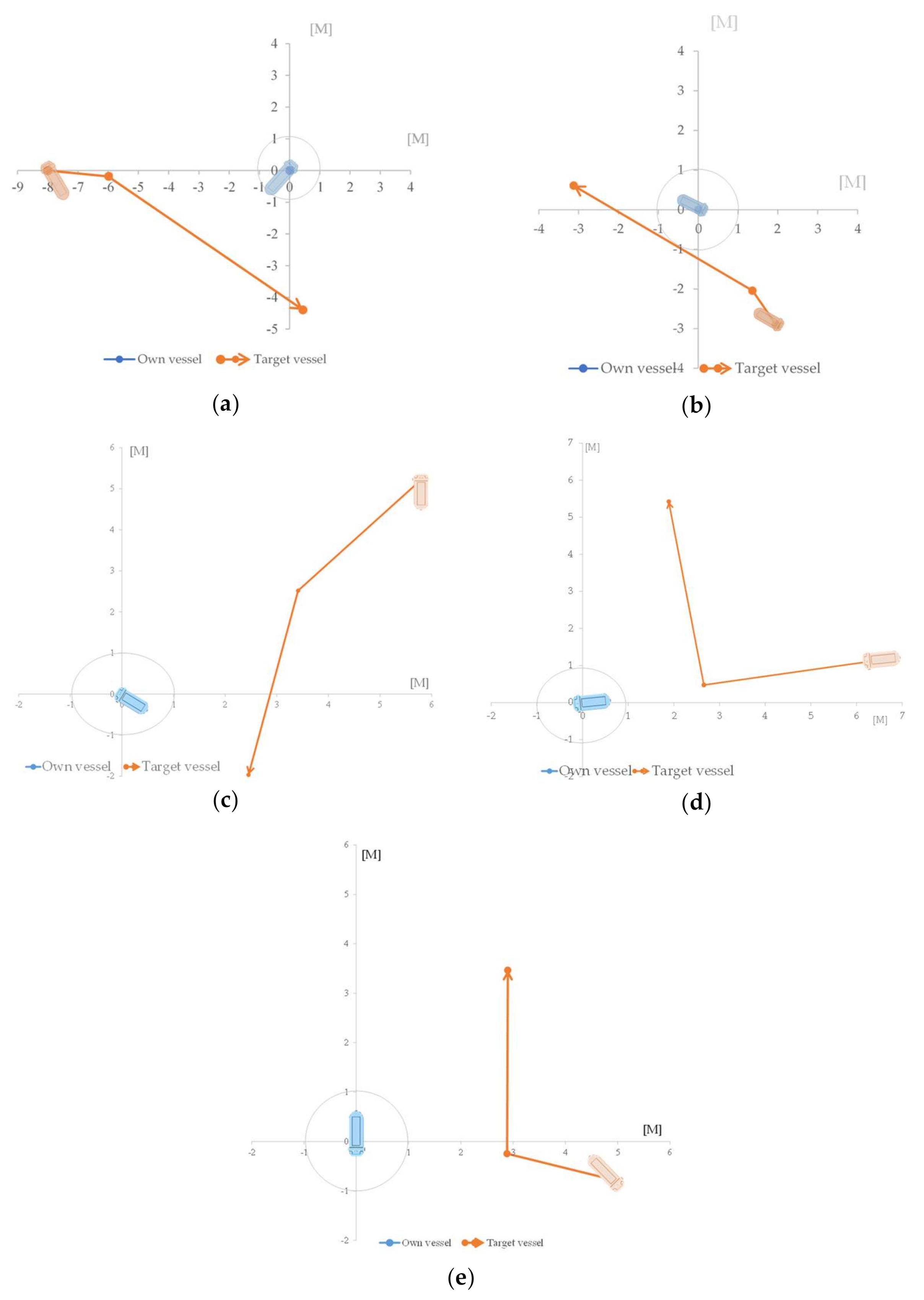
The functionality of the decision model was tested on different cases; the results of the simulations are shown in the following tables (Table 8, Table 9, Table 10, Table 11, Table 12 and Table 13). In all cases, the own vessel is in a give-way position: case 2 simulates a crossing situation with a target vessel approaching from starboard bow, case 3 simulates the situation where a target vessel acts as give-way vessel but violates rule 16 “Action by give-way vessel”, and the own vessel as a stand-on vessel must perform an action to avoid the collision. Case study 4 simulates the approach situation with the target vessel from RB 274°. The target, in this case, is a stand-on vessel (constrained by the draft), the own vessel is a give-way vessel. The simulation shows the avoidance at about 4 M, the fuzzy logic with the input parameters calculates a larger course alteration, thus ensuring a meeting at 3.8 M. Case study 5 tests the response of the fuzzy inference system for the approach situation according to COLREG rule 13. Case 6 simulates the approach situation with an RB value between 90 and 112.5°. The simulation observes the compliance of the model, which considers COLREG rules 8 and 19, which require that the vessel which detects the presence of another vessel by radar alone must avoid alteration of course towards the target vessel abeam or abaft the beam [29]. The graphical representation of the relative movement of the target vessel for each case study is shown in Figure 10.
5. Discussion
The simulations show the collision avoidance of a target vessel in three different navigation situations: head-on, crossing, and overtaking, whereby the own vessel has a give-way obligation. The simulations do not consider the manoeuvring characteristics of the vessels and are performed in a weather-free environment, eliding, for instance, wind and ocean currents. The results of the simulations show the decision at a subjectively determined time delay, but in real-time situations, the officer of the watch (OOW) usually has a certain timeframe to perform a collision avoidance manoeuvre that meets the desired safety criteria. For this reason, the quality of the model was also evaluated for different time delays to determine whether the decision meets the initial requirement of a DCPA value. We compared the timeframe of correct decisions with TCPA and obtained the percentage of time the model was still calculating course changes correctly and in accordance with the boundary conditions.
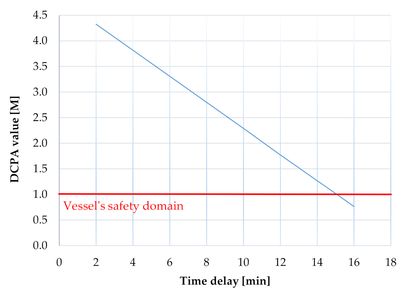
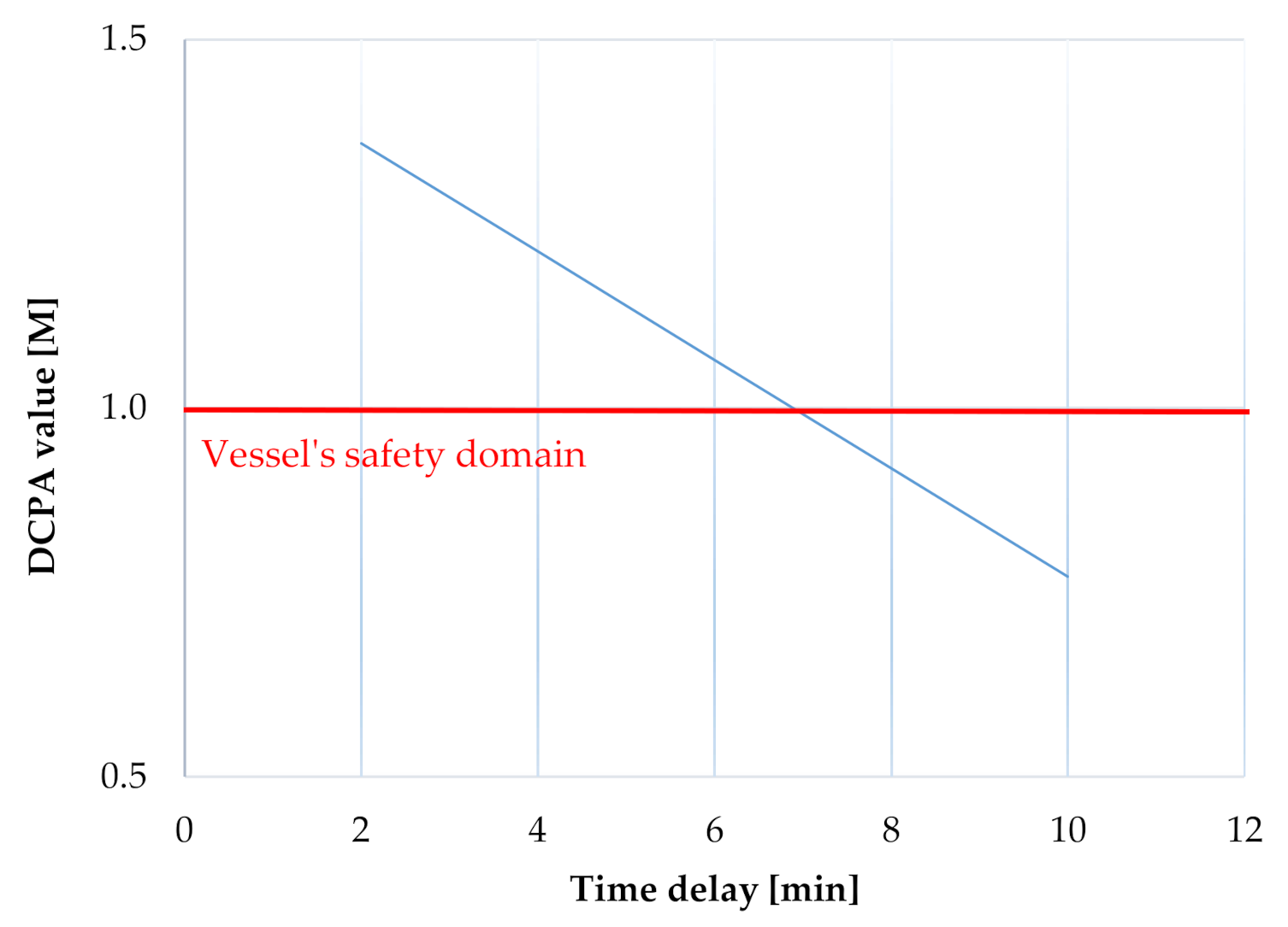
Case study 1: Course alteration is satisfactorily calculated in a timeframe of 15 min (see Table 14). After a 15 min time delay, the target vessel is at the distance less than 2 M, which is also the distance at which the decision model no longer operates according to the initial conditions.
The graph (Figure 11) represents the DCPA value at different time delays. The figure shows that the model calculates the proper decisions in the timeframe of 15 min, which is 77% of the total time available from the beginning of the observed situation when TCPA was calculated, which in simulation case study 1, was 19 min.
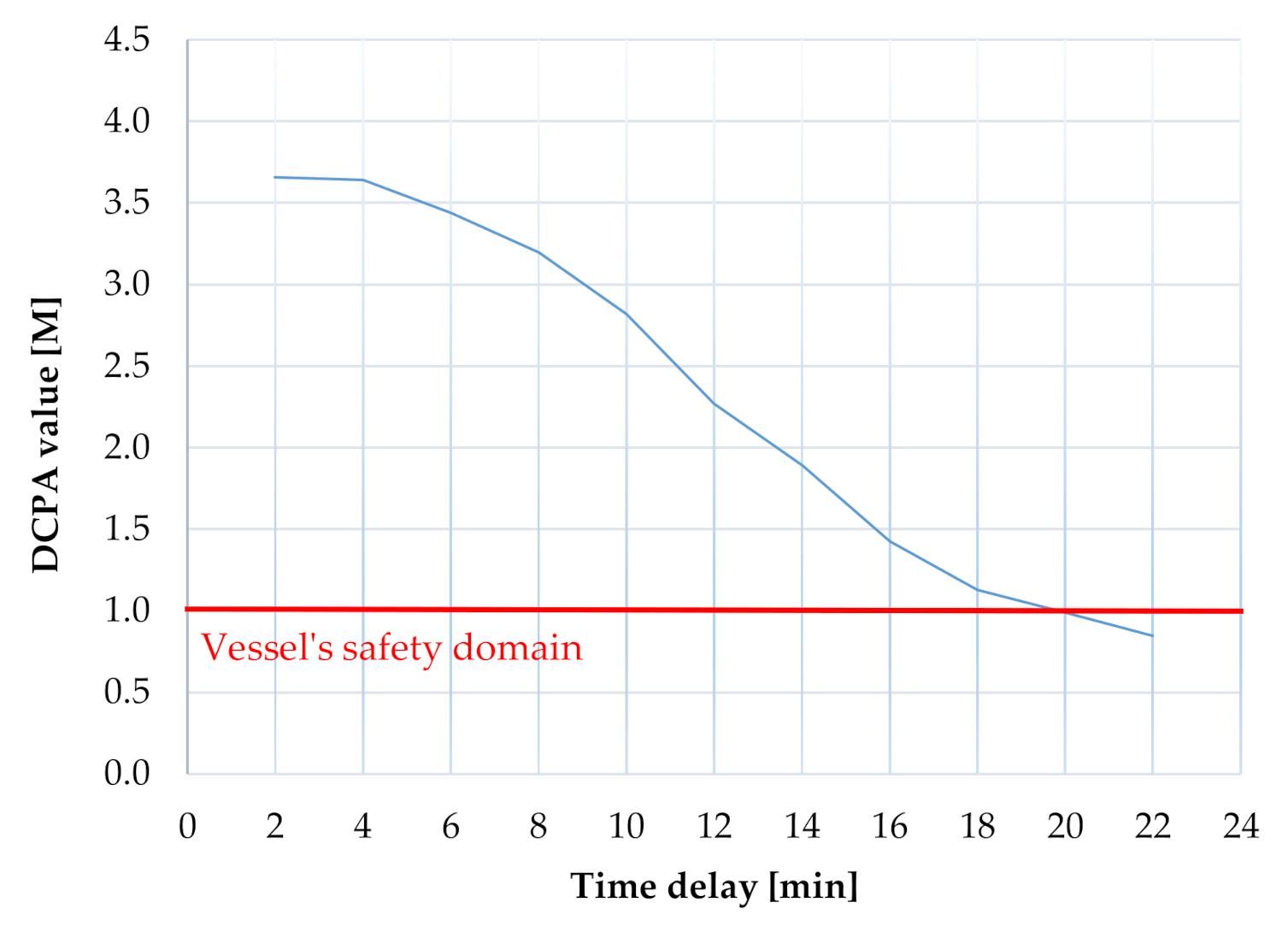
Case study 2: Table 15 shows the course alteration decision at different time delays. The safety condition DCPA (Figure 12) proves that the FIS calculates correct decisions in a timeframe between 2 and 16 min. With the time delay of 18 min, the course deviation is less than 30°, which according to Cockcroft [9], is not considered an appropriate course deviation. In 22 min, the AP of a target vessel is 1 M, and avoidance at this distance poses a high risk of vessel collision because the DCPA is less than 1 M. The model calculates the correct decisions in 67% of the total time available from the beginning of the observed situation.
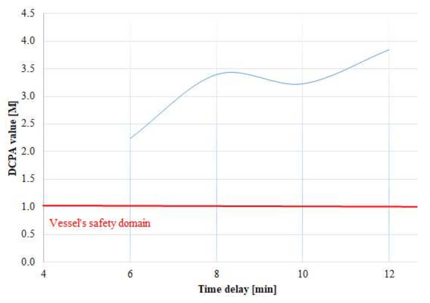
Case study 3: In this case, the target vessel is a give-way vessel which violates the COLREG rules. The result of the avoidance manoeuvre shows that the fuzzy inference system responds well even in emergencies (Table 16). Figure 13 represents the DCPA value at different time delays. The model responds well up to 7 min of the time delay, any alteration of course afterwards would jeopardize the safety of vessels.
Avoiding a dangerous vessel that violates the COLREG rules is performed in accordance with rules 8 and 19, thus changing the course to the side where there is no target vessel, in this case, the starboard side. The minimum DCPA condition is not met from 8 min on when the target vessel is at 2.1 M. The calculated change of course does not meet the criteria of minimum DCPA, so this condition is only partially confirmed. The model calculates the proper decisions in only 35% of the total time available from the beginning of the observed situation.
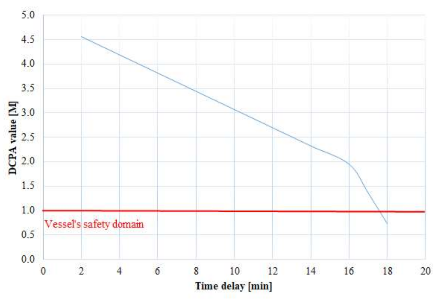
Case study 4: Example of a vessel encounter from the port side. As the target vessel is a vessel constrained by draft, the own vessel is obliged to avoid it. According to COLREG rule 8, the model proposed alteration of course to starboard side. The manoeuvre change is large enough to be detected on the radar. Table 17 shows the course alteration at different time delays, and Figure 14 shows the DCPA value at different time delays. The results show that the model responds well from the 2 to the 24 min. In the 24th min of observation, the distance of the observed vessel is 1.05 M. The model calculates the proper decisions in 89% of the total time available from the beginning of the observed situation.
Case study 5: In this case, the own vessel is in the position to overtake the target vessel. According to COLREG rule 13, overtaking is possible in both directions. The model offers the avoidance decision to starboard. Table 18 shows the calculated course alteration for different time delays.
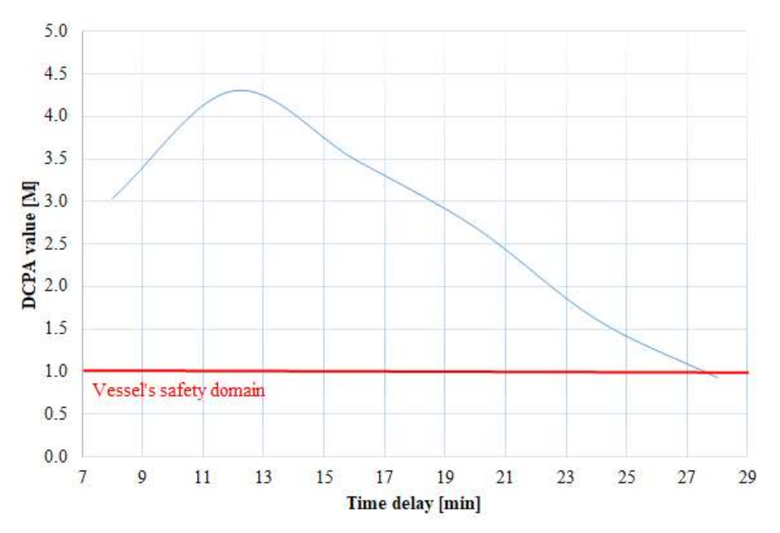
The observed DCPA condition demonstrates that fuzzy reasoning responds appropriately in the timeframe between 2 and 28 min. At 28 min (Figure 15), the vessel is at a distance of 1.1 M, and the model calculates the change of course as 95.3°, but due to the distance being too short, the manoeuvre does not reach a safe distance of approach as the calculated DCPA is 0.9372 M. The appropriate avoidance interval is between 2 and 27 min of time lag. The model calculates the proper decisions in 80% of the total time available from the beginning of the observed situation.
Case study 6: The case deals with a meeting situation from abeam. In this case, the alteration in course towards the target vessel is dangerous. Table 19 shows the calculated course change to port side at different time delays. The decision is satisfactorily calculated within the timeframe of 2 to 17 min, as shown in Figure 16. The condition of the vessel’s safety domain is met at all distances except for less than 1.7 M in the 18th min. The model calculates the proper decisions in 66% of the total time available from the beginning of the observed situation.
When planning a collision avoidance manoeuvre, course alteration is the most common and effective measure to avoid a close quarters situation, especially on the high seas. According to COLREG rules, the manoeuvre must be made in good time and should be clearly visible to other vessels in the vicinity. However, the distance at which vessels should begin the avoidance manoeuvre, particularly in adverse weather conditions or in restricted areas, is not quantified, leaving the decision to each individual OOW (officer of the watch).
An important factor to consider is vessel’s manoeuvrability, where the vessel type, size, and loading condition will affect its turning ability. In addition, external influences, such as the wind and local currents with their direction and force, affect the movement of the vessel and, hence, the course alteration, as they can make it difficult for the vessel to achieve the desired change of direction in the planned time. In particular, a large trim by the stern can change the vessel’s wind handling characteristics quite significantly. Local currents also cause the vessel to drift or affect its speed, and their influence depends on the vessel’s underwater surface exposed to the currents and their direction. In shallow waters, the turning circles become larger, but the ability to maintain course is better unless the low speed further affects the vessel’s responsiveness to course alterations. Therefore, when planning a course alteration, the OOW must consider all effects on the vessel’s manoeuvrability in order to make an effective and safe manoeuvre in good time and at a safe distance from the target vessel.
6. Conclusions
The article presents computer predictions of collision avoidance at sea by combining the traditional method of manual radar plotting with an artificial intelligence method—fuzzy logic. The advantage of fuzzy logic is in generating decisions based on inaccurate data that cannot be described by mathematical notation as they are expressed linguistically. Fuzzy logic thus imitates the human way of thinking, capable of solving complex tasks, although they may also contain a great deal of uncertainty. The peculiarity of the decision model is its tuning with the results of the database of correct solutions obtained by the traditional method of manual radar plotting. Based on them, the fuzzy sets and fuzzy rules were formed.
However, there were some shortcomings in model validation: in areas where decisions change from positive to negative and vice versa, greater errors can occur, and additional fuzzy sets must be created to reduce these errors. In addition, the validation process of the fuzzy inference system (fuzzy sets and fuzzy rules) takes a long time before it is able to make useful decisions.
The multi-parametric collision avoidance decision model uses parameters obtained based on approaching vessels without considering the vessel’s manoeuvrability and meteorological and oceanographic parameters that may additionally influence the choice of avoidance manoeuvre or the degree of deviation (change of course and/or speed of own vessel). The simulations also use the marine environment without vertical and/or horizontal constraints (coast, depth); the latter can further influence the choice of avoidance manoeuvre, especially the direction of avoidance. Further research will focus on avoidance using vessel speed and a combination of speed change and the course of own vessel as well as collision avoidance in a multi-vessel situation.
An important segment of further research and testing represents the integration decision model for all vessels that are included in the navigation situation and, thereby, to reduce the likelihood of violating the rules of avoidance between participating vessels.
Author Contributions
Conceptualisation, T.B. and A.A.; methodology, T.B., J.S. and R.B.; software, T.B.; validation, T.B., J.S. and R.B.; resources, A.A.; writing—original draft preparation, T.B.; writing—review and editing, T.B., A.A., and R.B. All authors have read and agreed to the published version of the manuscript.
Funding
The authors acknowledge the financial support of the Slovenian Research Agency (research core funding No. P2-0394, Modelling and Simulations in Traffic and Maritime Engineering).
Data Availability Statement
The data presented in this study are available on request from the corresponding author.
Conflicts of Interest
The authors declare no conflict of interest.
References
- Nielsen, M.; Petersen, J. Collision avoidance at sea—Practice and problems. In Proceedings of the 20th European Annual Conference on Human Decision, Kongens Lyngby, Denmark, 1 January 2001. [Google Scholar]
- Chauvin, C. Human factors and maritime safety. J. Navig. 2011, 64, 625–632. [Google Scholar] [CrossRef]
- MAIB. Accident Report MV P&O Nedlloyd Vespucci and Motor Yacht Wahkuna; Report No. 28; Marine Accident Investigation Branch: Southhampton, UK, 2003. [Google Scholar]
- IMO Resolution. Strategy for the Development and Implementation of E- Navigation, MSC 85, Anex 20; IMO Publishing: London, UK, 2009. [Google Scholar]
- Bole, A.G.; Wall, A.D.; Norris, A. Radar and ARPA Manual: Radar, AIS and Target Tracking for Marine Radar Users; Butterworth-Heinemann: Oxford, UK, 2013. [Google Scholar]
- Perera, L.; Carvalho, J.; Soares, C. Fuzzy logic based decision making system for collision avoidance of ocean navigation under critical collision conditions. J. Mar. Sci. Technol. 2011, 16, 84–99. [Google Scholar] [CrossRef]
- Szlapczynski, R.; Szlapczynska, J. Review of ship safety domains: Models and applications. Ocean Eng. 2017, 145, 277–289. [Google Scholar] [CrossRef]
- Wang, X.; Liu, Z.; Cai, Y. The ship manoeuvrability based collision avoidance dynamic support system in close-quarters situation. Ocean Eng. 2017, 146, 486–497. [Google Scholar] [CrossRef]
- Cockcroft, A.N.; Lameijer, J.N.F. Guide to the Collision Avoidance Rules; Elsevier: Amsterdam, The Netherlands, 2003. [Google Scholar]
- Statheros, T.; Howells, G.; McDonald-Maier, K. Autonomous Vessel Collision Avoidance Navigation Concepts, Technologies and Techniques. J. Navig. 2008, 61, 129–142. [Google Scholar] [CrossRef] [Green Version]
- Perera, L.P.; Carvalho, J.P.; Soares, C.G. Intelligent Ocean Navigation and Fuzzy-Bayesian Decision/Action Formulation. IEEE J. Ocean. Eng. 2012, 37, 204–219. [Google Scholar] [CrossRef]
- Perera, L.P.; Carvalho, J.; Soares, C.G. Solutions to the failures and limitations of Mamdani fuzzy inference in ship navigation. IEEE Trans. Veh. Technol. 2014, 63, 1539–1554. [Google Scholar] [CrossRef]
- Wu, B.; Cheng, T.; Yip, T.L.; Wang, Y. Fuzzy logic based dynamic decision-making system for intelligent navigation strategy within inland traffic separation schemes. Ocean Eng. 2020, 197, 106909. [Google Scholar] [CrossRef]
- Wu, B.; Yip, T.L.; Yan, X.; Soares, C.G. Fuzzy logic based approach for ship-bridge collision alert system. Ocean Eng. 2019, 187, 106152. [Google Scholar] [CrossRef]
- Hu, Y.; Park, G.K. Collision risk assessment based on the vulnerability of marine accidents using fuzzy logic. Int. J. Nav. Archit. Ocean Eng. 2020, 12, 541–551. [Google Scholar] [CrossRef]
- Zhuo, Y.; Tang, T. An Intelligent Decision Support System to Ship Anti-Collision in Multi-Ship Encounter. In Proceedings of the 7th World Congress on Intelligent Control and Automation, Chongqing, China, 25–27 June 2008. [Google Scholar]
- Su, C.; Chang, K.; Cheng, C. Fuzzy Decision on Optimal Collision Avoidance Measures for Ships in Vessel Traffic Service. J. Mar. Sci. Technol. Taiwan 2012, 20, 38–48. [Google Scholar]
- Pietrzykowski, Z.; Magaj, J.; Wołejsza, P.; Chomski, J. Fuzzy Logic in the Navigational Decision Support Processes onboard a Sea—Going Vessel; ICAISC Part I.; Springer: Berlin/Heidelberg, Germany, 2010. [Google Scholar]
- Liu, Y.; Du, X.; Yang, S.; Yeung, D.; Liu, Z.; Wang, X.; Yan, H. The design of a fuzzy-neural network for ship collision avoidance. Adv. Mach. Learn. Cybern. 2006, 3930, 804–812. [Google Scholar]
- Szłapczyński, R.; Szłapczyńska, J. COLREGS Compliance in Evolutionary Sets of Cooperating Ship Trajectories. Electron. J. Int. Group Reliab. Reliab. Theory Appl. 2011, 2, 11. [Google Scholar]
- Lee, S.; Kwon, K.; Joh, J. A fuzzy logic for autonomous navigation of marine vehicles satisfying COLREG guidelines. Int. J. Control Autom. Syst. 2004, 2, 171–181. [Google Scholar]
- Hu, Y.; Meng, X.; Zhang, Q.; Park, G.K. A real-time collision avoidance system for autonomous surface vessel using fuzzy logic. IEEE Access 2020, 8, 108835–108846. [Google Scholar] [CrossRef]
- Zadeh, L.A. Outline of a new approach to the analysis of complex systems and decision processes. IEEE Trans. Syst. Man Cybern. 1973, 1, 28–44. [Google Scholar] [CrossRef] [Green Version]
- Teodorović, D.; Vukadinović, K. Traffic Control and Transport Planning: A Fuzzy Sets and Neural Networks Approach (Vol. 13); Springer Science & Business Media: Berlin/Heidelberg, Germany, 2012. [Google Scholar]
- Mamdani, E.H. Application of fuzzy logic to approximate reasoning using linguistic synthesis. IEEE Trans. Comput. 1977, C-26, 1182–1191. [Google Scholar] [CrossRef]
- Brcko, T.; Svetak, J. Fuzzy reasoning as a base for collision avoidance decision support system. Promet Traffic Transp. 2013, 25, 555–564. [Google Scholar] [CrossRef] [Green Version]
- Naik, S.L.; Vimarshini, K.R. Prudent Ship Pilotage Using Trial Maneuver. In Proceedings of the 9th International Radar Symposium India, IRSI 13, Bangalore, India, 10–14 December 2013. [Google Scholar]
- Stateczny, A. Radar Navigation; GTN: Gdańsk, Poland, 2011. [Google Scholar]
- COLREG. Convention on the International Regulations for Preventing Collisions at Sea; IMO Publishing: London, UK, 1973. [Google Scholar]
- CMA CGM Bridge Safety Manual—Safe Passing Distance; CMA CGM Group: Marseille, France, 2015.
- Perera, L.P.; Carvalho, J.P.; Guedes Soares, C. Mamdani type fuzzy inference failures in navigation. In Proceedings of the IEEE International Conference on Industrial Informatics (INDIN), Lisbon, Portugal, 26–29 July 2011. [Google Scholar]
- Ni, S.; Liu, Z.; Cai, Y. Ship manoeuvrability-based simulation for ship navigation in collision situations. J. Mar. Sci. Eng. 2019, 7, 90. [Google Scholar] [CrossRef] [Green Version]
- Nguyen, M.; Nguyen, V.; Tamaru, H. Automatic collision avoiding support system for ships in congested waters and at open sea. In Proceedings of the Control, Automation and Information Sciences International Conference (ICCAIS), Ho Chi Minh City, Vietnam, 26–29 November 2012. [Google Scholar]
- Zhang, J.; Zhang, D.; Yan, X.; Haugen, S.; Soares, C.G. A distributed anti-collision decision support formulation in multi-ship encounter situations under COLREGs. Ocean Eng. 2015, 105, 336–348. [Google Scholar] [CrossRef]
- Pietrzykowski, Z.; Wołejsza, P.; Borkowski, P. Decision support in collision situations at sea. J. Navig. 2017, 70, 447–464. [Google Scholar] [CrossRef]
- Szłapczyński, R.; Szłapczyńska, J. A Target Information Display for Visualising Collision Avoidance Manoeuvres in Various Visibility Conditions. J. Navig. 2015, 68, 1041–1055. [Google Scholar] [CrossRef]
- Yan, X.; Chen, X.; Sang, L.; Zhang, D. A novel approach for assistance with anti-collision decision making based on the International Regulations for Preventing Collisions at Sea. J. Eng. Marit. Environ. 2012, 226, 250–259. [Google Scholar]
- Hwang, C.N. The integrated design of fuzzy collision—Avoidance and H∞ autopilots on vessels. J. Navig. 2002, 55, 20. [Google Scholar] [CrossRef]
- Hu, L.; Naeem, W.; Rajabally, E.; Watson, G.; Mills, T.; Bhuiyan, Z.; Salter, I. COLREGs-Compliant Path Planning for Autonomous Surface Vehicles: A Multiobjective Optimization Approach. IFAC-PapersOnLine 2017, 50, 13662–13667. [Google Scholar] [CrossRef]
- Fang, M.C.; Tsai, K.Y.; Fang, C.C. A Simplified Simulation Model of Ship Navigation for Safety and Collision Avoidance in Heavy Traffic Areas. J. Navig. 2018, 71, 837–860. [Google Scholar] [CrossRef]
- Huang, Y.; van Gelder, P.; Wen, Y. Velocity obstacle algorithms for collision prevention at sea. Ocean Eng. 2018, 151, 308–321. [Google Scholar] [CrossRef]
- Kim, D.; Hirayama, K.; Okimoto, T. Distributed Stochastic Search Algorithm for Multi-ship Encounter Situations. J. Navig. 2017, 70, 699–718. [Google Scholar] [CrossRef] [Green Version]
Figure 1.
Graphical interpretation of Mamdani fuzzy inference system [26].
Figure 1.
Graphical interpretation of Mamdani fuzzy inference system [26].

Figure 2.
Graphical representation of the collision risk calculation in a relative coordinate system.
Figure 2.
Graphical representation of the collision risk calculation in a relative coordinate system.

Figure 3.
Position of Closest Point of Approach (CPA) for a different relative course of approach.

Figure 4.
Manual radar plotting [26].
Figure 4.
Manual radar plotting [26].

Figure 5.
Excerpt from the database of correct solutions: green colour indicates a change of course to the starboard side, and red to the port side, at different parameters.
Figure 5.
Excerpt from the database of correct solutions: green colour indicates a change of course to the starboard side, and red to the port side, at different parameters.

Figure 6.
Comparison of the results of the database of correct solutions and the results of the fuzzy inference system.
Figure 6.
Comparison of the results of the database of correct solutions and the results of the fuzzy inference system.

Figure 7.
Graphical representation of the relative movement of the target vessel in a time delay in the polar coordinate system.
Figure 7.
Graphical representation of the relative movement of the target vessel in a time delay in the polar coordinate system.

Figure 8.
Fuzzy inference procedure using MATLAB Fuzzy Logic Toolbox.

Figure 9.
In the 11th minute, course alteration changes the relative path and velocity of the target.
Figure 9.
In the 11th minute, course alteration changes the relative path and velocity of the target.

Figure 10.
Planned trajectory of the target vessel: (a) case study 2, (b) case study 3, (c) case study 4, (d) case study 5, (e) case study 6.
Figure 10.
Planned trajectory of the target vessel: (a) case study 2, (b) case study 3, (c) case study 4, (d) case study 5, (e) case study 6.

Figure 11.
Calculated Distance to Closest Point of Approach (DCPA) at different time delays.

Figure 12.
Calculated DCPA at different time delays.

Figure 13.
Calculated DCPA at different time delays.

Figure 14.
Calculated DCPA at different time delays.

Figure 15.
Calculated DCPA at different time delays.

Figure 16.
Calculated DCPA at different time delays.


Table 1.
IF-THEN statements.
| IF | DCPA | Negative, Positive, Centre |
| AND | AP | Near, Middle, Far |
| AND | RB | Stbd Bow, Stbd Bow/Beam, Stbd Beam, Stbd Quarter, Stern, Port Quarter, Port Beam, Port Bow |
| AND | V | Low, Normal, High |
| THEN | Course alteration | Steady, Easy to port/starboard, Mid to port/starboard, Hard to port/starboard, Full to starboard, Full turn |
Table 2.
Initial parameters, 0 min.
| Own Vessel | Target Vessel | |
|---|---|---|
| C [°] | 340 | 161 |
| V [kn] | 16.5 | 13 |
| dt [M] | - | 9.5 |
| ωt [°] | - | 341 |
Table 3.
Collision risk assessment.
| DCPA [M] | 0.09 |
| TCPA [min] | 19.32 |
| CPA position | positive |
| RB [°] | 1 |
Table 4.
A new relative position of a target vessel for time delay 11 min.
| ωt [°] | 341.7 |
| dt [M] | 4.09 |
| RB [°] | 1.739 |
Table 5.
Calculated input parameters for fuzzy inference system (FIS).
| DCPA [M] | +0.09 |
| AP [M] | 4.09 |
| RB [°] | 1.739 |
| V [kn] | 16.5 |
Table 6.
Fuzzy rules.
| Rules | If DCPA | and AP | and RB | and SPEED | then Course Alteration |
|---|---|---|---|---|---|
| R1 | Centre | Near | S_Bow | High | Mid to Stbd |
| R2 | Centre | Near | S_Bow | Normal | Mid to Stbd |
| R3 | Centre | Middle | S_Bow | High | Mid to Stbd |
| R4 | Centre | Middle | S_Bow | Normal | Mid to Stbd |
Table 7.
Reassessment of the risks of collision.
| DCPA [M] | 2.0 |
| TCPA [min] | 8.1 |
| Vr [kn] | 26.3 |
| Cr [°] | 191 |
Table 8.
Initial data of own vessel.
| Case 2 | Case 3 | Case 4 | Case 5 | Case 6 | |
|---|---|---|---|---|---|
| Vessel type | Power-driven | Power-driven | Power-driven | Power-driven | Power-driven |
| C [°] | 225 | 303 | 134 | 81 | 359 |
| V [kn] | 20 | 13 | 10 | 23 | 17 |
Table 9.
Initial data of target vessel.
| Case 2 | Case 3 | Case 4 | Case 5 | Case 6 | |
|---|---|---|---|---|---|
| Vessel type | Power-driven | Power-driven | Constrained by draft | Power-driven | Power-driven |
| C [°] | 160 | 313 | 193 | 82 | 330 |
| V [kn] | 17 | 23 | 21 | 11 | 23 |
| dt [M] | 8 | 3.5 | 7.8 | 6.7 | 5 |
| ωt [°] | 270 | 146 | 48 | 80 | 99 |
Table 10.
Vessel’s encounter information.
| Case 2 | Case 3 | Case 4 | Case 5 | Case 6 | |
|---|---|---|---|---|---|
| DCPA [M] | 0.73 | 0.03 | 0.9 | 0.01 | 0.49 |
| TCPA [min] | 23.85 | 20.11 | 25.8 | 33.49 | 25.8 |
| CPA position | negative | positive | positive | negative | negative |
| RB [°] | 45 | 203 | 274 | 359 | 100 |
| Navigation situation | Crossing | Overtaking | Crossing | Overtaking | Crossing |
Table 11.
New relative position of a target vessel using time delay.
| Case 2 | Case 3 | Case 4 | Case 5 | Case 6 | |
|---|---|---|---|---|---|
| TD [min] | 6 | 6 | 12 | 20 | 11 |
| ω [°] | 268.3 | 146.2 | 53.6 | 79.9 | 94.9 |
| d [M] | 6.01 | 2.46 | 4.24 | 2.70 | 2.9 |
| RB [°] | 43.252 | 203.2 | 279.602 | 358.876 | 95.9 |
Table 12.
Input parameters and calculated decision.
| Case 2 | Case 3 | Case 4 | Case 5 | Case 6 | |
|---|---|---|---|---|---|
| DCPA [M] | −0.73 | 0.03 | 0.90 | −0.01 | −0.49 |
| AP [M] | 6.01 | 2.46 | 4.24 | 2.70 | 2.90 |
| RB [°] | 43.25 | 203.22 | 279.60 | 358.8 | 95.89 |
| V [kn] | 20 | 13.00 | 10.00 | 23 | 17.00 |
| Course alteration | 47.5 | 20 | 60 | 61.6 | −41.7 |
Table 13.
Reassessment of the collision risk.
| Case 2 | Case 3 | Case 4 | Case 5 | Case 6 | |
|---|---|---|---|---|---|
| DCPA [M] | 3.4 | 1.1 | 2.8 | 2.6 | 2.8 |
| TCPA [min] | 9.6 | 12.7 | 17.3 | −0.2 | 1.9 |
Table 14.
Course alteration at different time delay, case study 1.
| Time Delay [min] | AP [M] | RB [°] | Course Alteration [°] |
|---|---|---|---|
| 4 | 7.53 | 1.15 | 55.2 |
| 6 | 6.55 | 1.25 | 55.2 |
| 8 | 5.57 | 1.40 | 55.2 |
| 10 | 4.58 | 1.60 | 55.2 |
| 12 | 3.60 | 1.92 | 54.9 |
| 14 | 2.62 | 2.47 | 55 |
| 15 | 2.13 | 2.94 | 55 |
Table 15.
Course alteration at different time delay, case study 2.
| Time Delay [min] | AP [M] | RB [°] | Course Alteration [°] |
|---|---|---|---|
| 2 | 7.34 | 44.52 | 40.9 |
| 4 | 6.67 | 43.95 | 45.5 |
| 6 | 6.01 | 43.25 | 47.5 |
| 8 | 5.34 | 42.38 | 49.2 |
| 10 | 4.68 | 41.26 | 47.6 |
| 12 | 4.03 | 39.78 | 40.2 |
| 14 | 3.37 | 37.71 | 36.2 |
| 16 | 2.72 | 34.66 | 26.5 |
| 18 | 2.09 | 29.72 | 20 |
| 20 | 1.48 | 20.62 | 20 |
| 22 | 0.96 | 0.45 | 19.5 |
Table 16.
Course alteration at different time delay, case study 3.
| Time Delay [min] | AP [M] | RB [°] | Course Alteration [°] |
|---|---|---|---|
| 2 | 3.15 | 203.06 | 20 |
| 4 | 2.80 | 203.13 | 20 |
| 6 | 2.46 | 203.22 | 20 |
| 8 | 2.11 | 203.34 | 20 |
| 10 | 1.76 | 203.51 | 20 |
Table 17.
Course alteration at different time delay, case study 4.
| Time Delay [min] | AP [M] | RB [°] | Course Alteration [°] |
|---|---|---|---|
| 6 | 6.01 | 275.9 | 41 |
| 12 | 4.24 | 279.6 | 60 |
| 18 | 2.51 | 288.33 | 62.2 |
| 24 | 1.05 | 326.29 | 95 |
Table 18.
Course alteration at different time delay, case study 5.
| Time Delay [min] | AP [M] | RB [°] | Course Alteration [°] |
|---|---|---|---|
| 8 | 5.1 | 358.9 | 19.8 |
| 12 | 4.3 | 358.95 | 61.7 |
| 16 | 3.5 | 358.92 | 61.8 |
| 20 | 2.7 | 358.88 | 61.8 |
| 24 | 1.9 | 358.79 | 95.5 |
| 28 | 1.1 | 358.57 | 95.3 |
Table 19.
Course alteration at different time delay, case study 6.
| Time Delay [min] | AP [M] | RB [°] | Course Alteration [°] |
|---|---|---|---|
| 2 | 4.62 | 99.53 | −41.7 |
| 4 | 4.23 | 98.98 | −41.7 |
| 6 | 3.85 | 98.31 | −41.7 |
| 8 | 3.47 | 97.50 | −41.7 |
| 10 | 3.09 | 96.49 | −41.7 |
| 12 | 2.71 | 95.20 | −41.7 |
| 14 | 2.33 | 93.48 | −41.7 |
| 16 | 1.95 | 91.09 | −41.7 |
| 17 | 1.76 | 89.52 | −27.6 |
Publisher’s Note: MDPI stays neutral with regard to jurisdictional claims in published maps and institutional affiliations. |
© 2021 by the authors. Licensee MDPI, Basel, Switzerland. This article is an open access article distributed under the terms and conditions of the Creative Commons Attribution (CC BY) license (http://creativecommons.org/licenses/by/4.0/).
Share and Cite
MDPI and ACS Style
Brcko, T.; Androjna, A.; Srše, J.; Boć, R. Vessel Multi-Parametric Collision Avoidance Decision Model: Fuzzy Approach. J. Mar. Sci. Eng. 2021, 9, 49. https://doi.org/10.3390/jmse9010049
AMA Style
Brcko T, Androjna A, Srše J, Boć R. Vessel Multi-Parametric Collision Avoidance Decision Model: Fuzzy Approach. Journal of Marine Science and Engineering. 2021; 9(1):49. https://doi.org/10.3390/jmse9010049
Chicago/Turabian StyleBrcko, Tanja, Andrej Androjna, Jure Srše, and Renata Boć. 2021. "Vessel Multi-Parametric Collision Avoidance Decision Model: Fuzzy Approach" Journal of Marine Science and Engineering 9, no. 1: 49. https://doi.org/10.3390/jmse9010049
Note that from the first issue of 2016, this journal uses article numbers instead of page numbers. See further details here.