
Abstract
The integration of drug releasing polymeric layers on remotely navigable microcarriers is one of the most promising therapeutic strategies for a wide variety of diseases. Thanks to this approach, administration can be precisely targeted to a specific organ, limiting thus side effects and drug waste. In this context, the present work describes the fabrication of 3D printed and wet metallized microdevices intended for targeted drug delivery. Microtransporters are stereolithography printed and coated with a sequence of materials to impart them specific functionalities, like magnetizability and chemical inertness. Polypyrrole (PPy), in both bulk and nanostructured (NA) form, is electrodeposited as top layer to introduce drug delivery properties. Fabricated microdevices are characterized from the morphological and functional point of view. In particular, remote magnetic control and drug release behavior are investigated. Results obtained show a high magnetic maneuverability and good drug loading capability, which is further improved by nanostructuring the PPy layer applied on the surface of the microdevices. A possible application for the magnetically steered carriers described in the present work is localized drug administration for the therapy of many diseases typical of the gastrointestinal tract (e.g. Chron's disease).
Export citation and abstract BibTeX RIS
1. Introduction
Since the dawn of medical science, active principles delivery has always played a fundamental role in the vast majority of therapeutic approaches. Humans discovered since ancient times that some substances can be employed to diagnose, cure or even prevent the development of specific diseases. Historically, pharmacotherapy has always been based on three administration routes: enteral, parenteral or topical [1, 2]. All these approaches, however, suffer from the same drawback: drug delivery is not targeted. While the topical application of medications offers some degree of targeting, enteral or parenteral methods mostly rely on blood circulation to deliver the drug to the target organ [3]. This implies, indeed, that the drug reaches also parts of the body on which it does not exert any positive effect. On the contrary, many drugs are characterized by negative side effects if delivered to unwanted organs. As a consequence of these considerations, research started to focus on the development of pharmacotherapeutic approaches able to deliver active principles exclusively to the target organ, avoiding unwanted delivery to other parts of the body [4–6]. This potentially translates in a lower drug usage and in less drug side effects.
On one side, a considerable amount of experimentation has been carried out on the development of innovative materials for controlled medications release. Efforts on this side resulted in a wealth of possible approaches: functionalized nanoparticles [7, 8], magnetic nanospheres [9–12], liposomes [13–15], polymers [16–18], hydrogels [19, 20], dendrimers [21], metal-organic frameworks [22, 23] and DNA nanostructures [24]. Some of these materials (e.g. polymers and hydrogels) can be functionalized to release the drug only in correspondence of an external stimulus (electromagnetic radiation, heat, pH variation, ...) [17, 20, 22, 25], allowing thus a highly controlled drug delivery. One of the most promising materials for smart drug delivery is polypyrrole (PPy) [26, 27]. This conductive polymer is characterized by significant advantages: it is fully biocompatible [28], nearly inert, easy to produce and costless. Furthermore, drug release from PPy can be tuned and enhanced by applying an external potential [29–33]. This effect is connected to the red/ox capability of PPy films [34], which translates into different drug permeability levels according to the electrochemical state of the material. Thanks to its inertness, a wide variety of small molecules can be loaded in PPy. Some notable examples from the current literature include anti-schistosomiasis drugs (praziquantel and trichlorfon) [35], anti-inflammatory agents (dexamethasone phosphate) [32], antibiotics (meropenem) [32] or antipsychotic drugs (risperidone) [36]. Finally, PPy is one of the few polymers that can be efficiently electrodeposited [26]. The advantage of using electrodeposition for PPy manufacturing resides in its low cost and high versatility. Additionally, electrodeposited layers can be easily nanostructured to enhance drug loading capability by employing the inverse opal technique [37, 38] or by following a direct codeposition/etching approach [39].
In addition to materials improvement, another important step toward smart drug release is the development of wirelessly controlled microdevices able to in-vivo navigate human body [40–44]. Such microdevices, also known as microrobots, possess the ability to swim in biological fluids, are normally powered employing different external stimuli (chemical reactions [45], magnetism [46], light [47], ultrasounds [48]) and can be designed to fulfill a large variety of tasks [49, 50]. For the scope of the paper, they can be coated with a drug releasing material and guided to the target organ [51]. By doing this, the active principle can be released exclusively in correspondence of the target zone, avoiding thus uncontrolled administration in other parts of the body. As an evidence of the validity of this approach, a good number of state-of-the-art examples can be retrieved [52–56]. Some of such examples make direct use of PPy layers to carry out targeted drug delivery [57–59].
Targeting therapies by mean of microrobots may be advantageous for the treatment of a great variety of diseases, even if the methodology expresses its highest potential in the case of highly localized disorders. A typical example is Crohn's disease, which is a localized inflammatory bowel disease able to affect specific sections of the gastrointestinal apparatus [60]. The treatment currently employed for Crohn's disease relies on the administration of antibiotics, aminosalicylate drugs, corticosteroids and chemotherapeutic agents (following traditional administration routes) [60]. It appears evident, due to the highly localized nature of the disease, that targeted drug delivery may have a beneficial effect in the clinical treatment of Crohn's disease. To this extent, small molecule drugs like 5-aminosalicylic acid, hydrocortisone or ciprofloxacin can be potentially loaded in PPy-coated microcarriers and administered locally to alleviate Crohn's disease symptoms or to perform curative tasks.
In the present work, we propose the fabrication of 3D printed and wet metallized microdevices for controlled drug delivery. Pill-shaped microrobots, characterized by features ranging between hundreds of micrometers to millimeters, are fabricated employing micro stereolithography (μSLA) and coated with a sequence of functional materials. The dimensions of the microdevices are analogous to other examples reported in literature [49, 50, 58] and are compatible, for example, with a potential use in the gastrointestinal tract to locally treat Crohn's disease. From the constructive point of view, a magnetic CoNiP alloy is deposited to make possible magnetic actuation. Pt is deposited to introduce a layer of chemically inert material, while PPy is deposited to allow drug release. Furthermore, PPy is nanostructured to further enhance drug loading efficiency. Due to the complex geometry of the devices, PPy nanostructuring via inverse opal is impractical. For this reason, PPy is nanostructured employing a direct codeposition/etching technique [39]. Final devices are characterized from the morphological point of view, wirelessly navigated employing magnetic fields and their drug release performances are investigated.
2. Experimental methods
2.1. 3D printing procedure
Devices were 3D printed using a commercial stereolithography machine (model 028 J Plus) produced by Digital Wax Systems (DWS). As photocurable material, a urethane-acrylate-based resin (DL260 by DWS) filled with 20% wt. silica-alumina nanoparticles was employed. CAD models were designed using Solidworks software (Dassault Systèmes, France) and corresponding microdevices were printed in three different shapes, namely A, B and C. Figure S1 (available online at https://stacks.iop.org/MFM/3/045003/mmedia) and table S1 report the nominal dimensions for all the samples. Before printing, the CAD models were processed with a 3D parametric software (Nauta+, DWS systems), and oriented vertically on the printing platform to ensure the highest printing resolution. Printing supports were introduced by exploiting the autosupport function of the software. Cylindrical pillars with a diameter ranging between 200 μm and 500 μm were printed. The resulting processed virtual models were subsequently sent to Fictor (DWS Systems), the software that directly controlled the 3D printer, and sliced according to the user-imposed building parameters. Laser speed was ranged between 250 mm s−1 and 4300 mm s−1 and the layer thickness was varied between 25 μm and 10 μm. At the end of the printing step, the samples were washed in ethanol to remove unreacted resin, dried with nitrogen and post-cured by exposing them to UV radiation (λ = 405 nm) for 30 min.
2.2. Devices metallization procedure
All the chemicals employed for the metallization process were purchased from Sigma Aldrich and used as received. During the wet metallization process, printed devices were left connected to the printing supports and the printing bases. Initially, a copper layer was deposited by mean of electroless deposition to make conductive the surface of the devices. Samples were sonicated in ethanol for 5 min to remove organic contamination. They were subsequently washed with deionized water, dried with nitrogen and then immersed for 30 min in a KOH solution (200 g l−1) at 45 °C to etch their surface. No stirring was used and the samples were washed with deionized water at the end of the process. Surface was activated for electroless deposition using an activation process comprising two steps: immersion for 5 min in a Pd-based commercial activator (Neoganth 834 by Atotech), immersion for 30 s in a reducing bath composed of NaBH4 (20 g l−1). No stirring was employed and the activation procedure was repeated three times on the devices, which were not washed after the immersion in the Neoganth activator but they were rinsed after the passage in the reducing solution. Electroless copper was deposited using a bath containing the following components: CuSO4·5H2O (20 g l−1), Na2EDTA (40 g l−1), C10H8N2 (10 mg l−1), K3Fe(CN)6 (10 mg l−1), C2H2O3 (10.5 g l−1). Deposition was performed at 45 °C and pH 12 (modified with NaOH) for 15 min. CoNiP, copper, Pt and PPy were electrolytically deposited after the initial electroless copper layer. The printing bases (which were connected to the devices via the printing supports) were contacted with a current generator and immersed in the various electrolytes. CoNiP electrolytic bath formulation was as follows: NiCl2·6H2O (25.92 g l−1), CoCl2·6H2O (26.74 g l−1), NaH2PO2·H2O (12.84 g l−1), NaCl (40.91 g l−1), H3BO3 (24.72 g l−1), saccharine (0.88 g l−1). A nickel plate was used as anode, pH was set to 3 (using KOH or HCl), no stirring was employed and deposition was performed at room temperature and at a current density equal to 10 mA cm−2 (for 40 min). Copper was deposited using a copper anode from a commercial acidic solution, Cuproplus (by Tecnochimica), at ambient temperature, moderate stirring and 10 mA cm−2 (for 2 min). Pt was deposited from the following electrolyte: Na3C6H5O7 (100 g l−1), C6H17N3O7 (5 g l−1), [NH4]2[PtCl6] (15 g l−1). Deposition was carried out using an inert anode, at 50 °C, moderate stirring and using a current equal to 20 mA cm−2 (for 15 min). PPy was deposited with or without poly(methyl methacrylate) (PMMA), following existing literature [39]. To obtain samples not containing codeposited PMMA, PPy was deposited from: C4H5N (6.7 g l−1), C18H29NaO3S (34.8 g l−1). PPy was electropolymerized using graphite as cathode, at ambient temperature, in stagnant conditions ad employing a current density equal to 10 mA cm−2 (for 5 min). To obtain samples containing codeposited PMMA, the PPy solution previously described was additivated with PMMA nanoparticles (40 g l−1). Such PMMA nanoparticles were produced following a methodology available in literature [39]. Deposition parameters were analogous to PMMA-free PPy, except for deposition time (90 s) and current density (20 mA cm−2). After PPy/PMMA codeposition, samples were rinsed with demineralized water and subjected to a chemical etching step in a 1:3 v/v toluene‐acetone mixture for about 3 h. This process yielded devices covered with nanoporous PPy layers. At the end of all the deposition steps, devices were removed from the printing supports.
2.3. Devices characterization
For SEM characterization, a Zeiss EVO 50 microscope was used. Such instrument was equipped with an Oxford Instruments Model 7060 EDS module, which was used to perform energy dispersive x-ray spectroscopy (EDS). SEM observations on the cross-sections were carried out by manually breaking the devices at room temperature. Magnetic properties of the materials were evaluated by mean of a Princeton Measurement Corp. MicroMag 3900 vibrating sample magnetometer (VSM) system.
2.4. Magnetic actuation
Magnetic actuation was performed employing a manipulation setup called Octomag [61]. Both magnetic field gradients and rotating magnetic fields were applied, as described in the results section. Samples were magnetized placing them in contact with a cylindrical 3 × 1 cm NdFeB permanent magnet (N45 grade) and their actuability was evaluated using water as medium. In particular, they were moved inside three custom made environments: a circular basin, a serpentine channel and a C-shaped channel.
2.5. Drug release tests
Drug release capability of the devices was evaluated employing Rhodamine B (RhB). Samples were immersed in a RhB 10 mg l−1 aqueous solution. They were left in this solution overnight for 18 h to allow drug loading through RhB diffusion inside the polymer. The devices were then extracted from the solution, rinsed quickly with demineralized water and placed in a 1 ml demineralized water volume each. The glass cuvette containing both the water and the device was covered to avoid evaporation and isolated from sunlight to escape uncontrolled RhB degradation. Periodic withdrawals of the solution containing the drug releasing samples, in combination with the use of an Infinite 200 PRO spectrophotometer (Tecan), were employed to build a drug release curve. Released amount of RhB was evaluated comparing the measured absorption of the solution at 540 nm with the absorption of a RhB reference solution (1 mg l−1) at the same wavelength.
2.6. Contaminants release tests
Inductively Coupled Plasma-Optical Emission Spectrometry (ICP-OES) was performed to determine the amount of contaminants released by the microdevices. Three samples were immersed in phosphate buffered solution (PBS) for 2 d and then removed. A Thermo Scientific iCAP PRO ICP-OES was used to measure the concentration of pollutants (Co, Ni, P, Cu) in the resulting solution.
3. Results and discussion
3.1. Microdevices design
The design of the navigable microdevices was defined taking in consideration their potential applicability to drug delivery in the gastrointestinal apparatus. Thanks to the relatively large characteristic sections of the different zones of the digestive system, micrometric-sized devices are typically not required. Moreover, comparatively large devices translate into an easier and cost effective 3D printing procedure. In particular, characteristic dimensions were defined as follows: 3 mm for the external diameter and 8 mm for the overall length. Figure S1 and table S1 report in detail all the dimensions of the samples produced. In general, the devices presented a zone having cylindrical symmetry to allow rolling actuation. Moreover, the devices were characterized by a pill-like shape, which allowed to avoid sharp edges that could potentially damage internal tissues or interfere with the motion of the device.
To increase their surface, and consequently the amount of released drug, devices were microstructured. In particular, three different geometries (A, B and C) were created. A, B and C geometries are visible in figures 1(a), (b) and (c) respectively. The corresponding 3D models are visible in figures 1(d), (e) and (f). These are characterized by different total surface area values S (165.84 mm2 for A, 175.96 mm2 for B and 131.41 mm2 for C) and are employed to demonstrate the influence of external surface area on the final amount of released drug. To evaluate area improvement, a non-microstructured equivalent device can be considered. Such hypothetical device has the same external dimensions of the microstructured ones and is composed of a cylinder connected to two semispherical parts. In this case, the surface S0 is equal to 75.4 mm2. By comparing this value with the areas of microstructured devices, the following ratios S/S0 can be calculated: 2.2 (corresponding to 220% of the non-microstructured area) for A, 2.33 (corresponding to 233%) for B and 1.74 (corresponding to 174%) for C. By comparing these values with the ones calculated for the non-microstructured geometry, it appears evident that microstructuring considerably enhanced total surface keeping constant the external dimensions of the device.

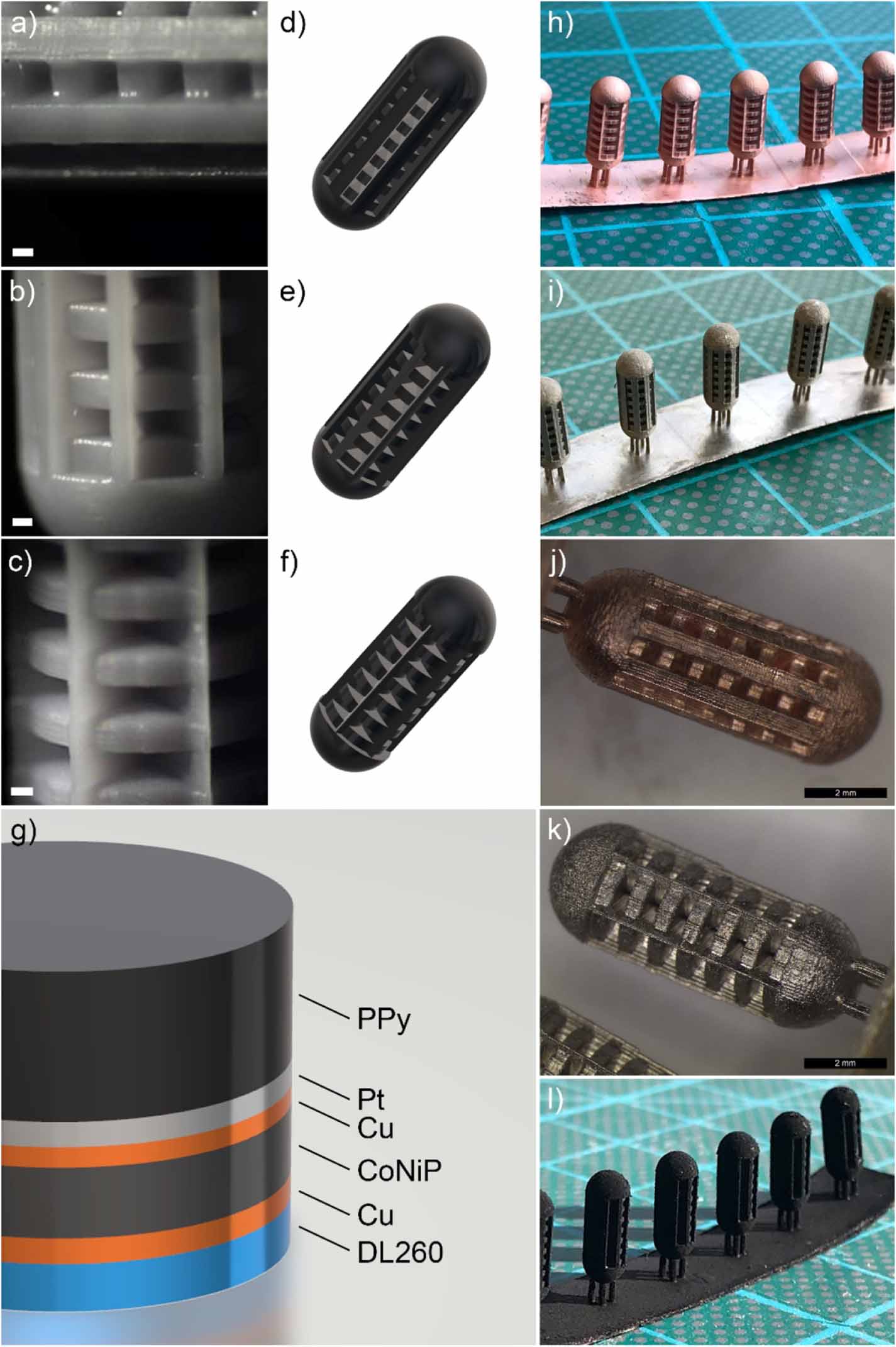
Figure 1. Optical microscope images of the three geometries: A (a), B (b) and C (c); 3D models for the three geometries: A (d), B (e) and C (f); scheme of the layers sequence (g); visual appearance of the microdevices after the application of electroless Cu (h), CoNiP (i), electrolytic Cu (j), Pt (k) and PPy NN (l).
Download figure:
Standard image High-resolution imageTo further enhance loading capability, a second level of structuring was introduced by depositing the PPy layer in nanoporous form [39]. For comparison, bulk PPy-coated samples were deposited as well. Accordingly, produced devices were further subdivided into non-nanostructured (NN) and nanostructured (NA). This resulted in six total classes of finished devices, identified by six codes (as reported in table 1).
Table 1. Devices classification and geometrical properties.
| Code | Geometry | PPy layer | Nominal S (mm2) | Nominal S/S0 |
|---|---|---|---|---|
| A-NN | A | Bulk | 165.84 | 2.2 |
| B-NN | B | Bulk | 175.96 | 2.33 |
| C-NN | C | Bulk | 131.41 | 1.74 |
| A-NA | A | Nanostructured | 165.84 | 2.2 |
| B-NA | B | Nanostructured | 175.96 | 2.33 |
| C-NA | C | Nanostructured | 131.41 | 1.74 |
It is important to emphasize that surface and S/S0 ratio are nominal. They do not take into account, for example, the influence of nanostructuring on total surface of the PPy layer in NA samples.
3.2. Microdevices production
At the beginning of the production process, microdevices were 3D printed employing μSLA. Six samples were printed together in each production batch (figure 2S). Printing supports were employed to support the devices during the printing. Supports were placed on a square printing base, which is clearly visible in figure S2. In standard 3D printing processes, printed parts are removed from the supports at the end of the printing. In the present work, however, printing base and supports were exploited to provide electrical connection during electrodeposition. For this reason, samples were not immediately removed. Figures 1(a), (b) and (c) depict the result obtained in the case of geometries A, B and C respectively. Dimensional adherence of 3D printed device to the theoretical CAD model was verified and the results are reported in table S2. In general, all the samples were characterized by a good dimensional fidelity, with maximum dimensional deviations in the order of 6.27% (for small features).
After the 3D printing step, devices were functionalized by depositing on their surface a sequence of layers (whose structure is visualized in figure 1(g)) by mean of wet deposition. Since the surface was non-conductive, the only wet technique viable for the deposition of the first step was electroless plating. For this reason, an electroless copper layer was deposited on the DL260 resin to provide a conductive surface for subsequent electrolytic deposition (figure 1(h)). Such Cu layer does not have an active function and, for this reason, its thickness was kept relatively low (400 nm). Once the surface was made conductive, electrolytic deposition was carried out. Evidently, samples must be connected to a current generator and this consideration motivates the choice of leaving them on the printing supports. Indeed, also the printing base and the supports are covered with copper during the initial electroless step (figure 1(h)). Consequently, electrolytic deposition was performed connecting one side of the base with the generator and immersing the base itself in the electrolyte. Following this approach, a CoNiP layer was electrolytically deposited on top of the conductive Cu layer (figure 1(i)). The function of this coating, which is ferromagnetic and permanently magnetizable, is to allow magnetic actuation. In fact, by applying an external magnetic field, a force or a torque can be applied on the device. Equations (1) and (2) describe the phenomenon [44].


V is the volume of magnetic material, B is the applied external magnetic field and M is the magnetization of the material. As evident from the equations, the intensity of the force obtained depends from the volume of the magnetic material. Equivalently, it depends on the thickness of the magnetic layer applied. For this reason, thickness of CoNiP was carefully selected to allow sufficient force for rolling and gradient actuation. It was decided to apply 6 µm of material. On top of CoNiP, a Cu adhesion layer was deposited with a commercial acidic electrolyte (figure 1(j)). The function of such layer, whose thickness was limited to 400 nm, is purely to provide adhesion between CoNiP and Pt. The latter was applied on top of the copper layer to isolate the CoNiP from the external environment (figure 1(k); thickness is equal to 500 nm). Co and Ni are widely recognized as teratogenic elements and their release in the human body must be necessarily avoided. For this reason, Pt was selected as inert (and therefore corrosion resistant) layer to protect CoNiP. The final layer was PPy, both in NA or NN form (figure 1(l)). NN PPy was characterized by a nominal thickness of 8 μm, while NA PPy was characterized by a thickness equal to 4 μm. At the end of the metallization process, devices were manually detached from the supports.
The metallization approach followed in the present work is faster and easier with respect to the recently developed barrel-like plating methodology [49]. It presents however a major drawback: some parts of the samples remain uncoated at the end of the process, since printing support are removed only at the end of the metallization. For this reason, the contact zone between each support and the device is not covered by any layer. It presents, on the contrary, an exposed layer of CoNiP and Cu.
3.3. Morphological characterization
Finished devices were morphologically characterized using SEM. Figure 2 shows the results obtained.
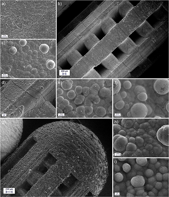
Figure 2. SEM morphology of the electroless Cu layer (a) on a B geometry; SEM morphology of the CoNiP layer (b), (c) and (d) on a A geometry; SEM morphology of the electrolytic Cu layer (e) on a A geometry; SEM morphology of the Pt layer (f) on a C geometry; SEM morphology of the PPy NN layer (g), (h) on a A geometry; SEM morphology of the PPy NA layer (i) on a C geometry.
Download figure:
Standard image High-resolution imageThe surface of the as printed DL260 resin (figure S3) is characterized by the presence of spherical particles embedded in a polymeric matrix. The first are silico-alluminate nanoparticles, which are added to the resin to compensate shrinking during printing and to enhance mechanical properties, while the latter is a urethane-acrylate-based material. After the first electroless metallization step, the surface of the samples appeared uniformly covered by a continuous layer of copper (figure 2(a)). The metal looks fine grained and crack-free. Following copper deposition, a layer of CoNiP was plated on the surface. Figure 2(b) gives a low magnification view of the general morphology of an A device, while figure 2(c) presents a higher magnification of the CoNiP film morphology. The surface of the device covered with CoNiP was characterized by a nodular appearance, which is a direct consequence of the typical columnar growth observed in most electrodeposited layers. By looking at the surface of the CoNiP layer, the presence of many cracks can be immediately detected. These cracks, clearly evident in figure 2(d), are a result of the internal stresses induced by the electrodeposition process. Alloys plated from chloride baths and containing phosphorus in the low to medium concentration range are all characterized by consistent internal stresses as a consequence of the crystal lattice distortion introduced by the presence of P itself [62]. Obviously, cracks do not have any effect on devices magnetic actuability, since the force applied by an external field only depends on the volume of magnetic material and on its magnetization (equations (1) and (2)). After CoNiP, a Cu adhesion layer was deposited (figure 2(e)). Besides providing adhesion between CoNiP and Pt, this layer also efficiently sealed the cracks present in the CoNiP layer (figure 2(d)) and produced a more accentuated nodular morphology on the surface. Pt was deposited on top of the Cu adhesion layer, resulting in the morphology visible in figure 2(f).
PPy, both NA and NN, was electrodeposited as final layer on the microdevices. Figure 2(g) depicts a low magnification image of an A device coated with NN PPy. The surface of the PPy coating was characterized by a relatively high level of roughness, which is typical for many PPy layers growth using electrodeposition. Surface morphology can be better appreciated in figure 2(h), where a high magnification of the surface of an A device is represented. Figure 2(i), on the contrary, reports the surface morphology observed on the surface of a C device covered with NA PPy. The surface appears covered by a nanometric porosity, which resulted from the codeposition and subsequent etching of PMMA nanospheres [39].
Prepared samples were sectioned to investigate their internal structure. Figure 3 depicts the result obtained by directly breaking a C sample and observing the cross section in correspondence of the surface via SEM. EDS elemental mapping was also performed on the section to evidence the distribution of the different elements.
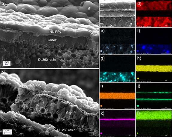
Figure 3. SEM cross-sections of a A-NN (a) device and of a C-NA (b) device; elemental mapping acquired on the cross-section of a A-NN device: secondary electrons morphology (c), C distribution (d), O distribution (e), Al distribution (f), Si distribution (g), Co distribution (h), Ni distribution (i), Cu distribution (j), Pt distribution (k), S distribution (l).
Download figure:
Standard image High-resolution imageIn general, all the layers were found to be adherent and continuous on the surface of all the devices. The nanostructuring left by the PMMA nanoparticles is evident in figure 2(b), while the morphology of bulk PPy can be seen in figure 2(a). It is interesting to highlight the high mechanical interlocking observable at the interface between the metallic layers and the DL260 resin, which is at the base of the good adhesion observed in the case of metals deposited on DL260 [63]. By looking at the figures from 3(c) to (l), the distribution of the elements can be appreciated. The Al and Si signals clearly highlight the presence of the silico-aluminate particles embedded in the DL260 stereolithography resin. Co, Ni, Cu and Pt signals reveal the presence of the different metallic layers. Finally, C and S signals evidence the presence of the PPy layer.
The SEM analysis of the cross sections revealed a significant thickness non-uniformity. This effect is a direct consequence of the electrodeposition process employed to deposit the different layers. Non-planar surfaces, in fact, are characterized by uneven electric field distribution during electrodeposition. Thus, protruding parts present field lines accumulation and higher deposition rates, while recessed zones present more spaced lines and reduced deposition rates. The result is that the outer parts of the devices presents thicker electrodeposited layers. For comparison, CoNiP thickness in figure 3(a) is 7 μm, in figure 3(b) it is 5.2 μm and in figure 3(c) it is 6 μm. NN PPy thickness in figure 3(a) is equal to 4.5 μm, while in figure 3(c) it is equal to 8.4 μm. PPy in particular, due to its peculiar electrolymerization mechanism, strongly suffers from electric field disuniformities. A variation of few mA cm−2 results in a high difference in growth rate of the PPy layer [39]. As a consequence, some zones of the devices present PPy thicknesses double with respect to some others. However, thickness variations resulting from the electroplating process were found to have no detrimental effect on the global functionality of the devices produced.
3.4. Magnetic actuation
Actuability of the devices was evaluated by applying controlled magnetic fields. Thanks to the presence of a semi-hard magnetic material like CoNiP, the magnetic behavior of the device can be programmed according to the actuation mechanism desired. Electrodeposited Co-rich CoNiP is normally characterized by cohercivity values in the 1000–2000 Oe range [64]. Consequently, devices are able to retain a permanent magnetization. In the specific case of the CoNiP alloy deposited on the devices, VSM was employed to evaluate its magnetic properties. As visible in figure 4(a), a cohercivity value equal to 1026 Oe was measured along the longitudinal axis of a A-NN device (0°), while a value of 1090 Oe was observed in the transversal direction (90°). These values, which are typical of a semi-hard magnetic material, justify the ability of the final device to retain a permanent magnetization along a predefined direction. Another important observation can be done on figure 4(a) by comparing the two hysteresis cycles (in the longitudinal and transversal directions): they almost completely superimpose. In normal conditions, electrodeposited layers are characterized by a high magnetic anisotropy, which is a result of the columnar grain growth typical of electrodeposition [65]. Indeed, if CoNiP is deposited on a planar substrate [64], magnetic properties along the out-of-plane direction are considerably higher than along the in-plane direction. To understand the conflicting behavior observed with the devices, it is fundamental to consider their complex shape. CoNiP is deposited on their surface along a great variety of orientations. For this reason, even if locally the CoNiP layer is characterized by a high anisotropy, the global magnetic behavior of the device is an average. This effect can be desired, since it allows to attenuate the magnetic anisotropy normally achieved with electrodeposited layers.

Figure 4. VSM performed on a C-NN sample (a); speed vs. frequency data acquired for the three geometries in water (b); double 90° turn actuation (from (c) to (f)); circular actuation (from (g) to (j)); the rotation axis of the magnetic field is represented by a red dashed line named 'a'.
Download figure:
Standard image High-resolution imageTo program the magnetic behavior of the devices, they were magnetized along two axis (as visible in figure S4) using a permanent NdFeB magnet. In one case, magnetization was directed along the longitudinal axis of the device, while in the second case it was applied along the transversal axis (parallel to the radius of the device). A first approach that can be employed to move the devices is rolling actuation, which takes advantage of a magnetization perpendicular to the symmetry axis. This actuation method has already been described in existing papers [49, 50] and is based on the application of a torque on the device, which determines a rotation around its symmetry axis. To do this, magnetization M of the CoNiP layer must necessarily be oriented along the radius of the device. If a rotating external field B is applied, the resulting torque rotates the device and allows linear motion in case the device is in contact with a solid substrate.
To modify the direction of the motion, it is sufficient to vary the direction of the rotation axis of the external magnetic field. Figure 4 depicts two examples of directional control performed on a B-NN device. In figures from 4(c) to (f), the device initially moved towards the right as a result of a magnetic field rotating around the axis shown in figure 4(c). At a certain point, the axis was turned by 90° (figures 4(d) and (e)) and the device started moving downward. Subsequently, the axis was reverted back to its original orientation (figure 4(f)) and the device again moved toward the right (supporting video 1). Figures from 4(g) to (j) depict a circular motion, obtained with a continuous variation of the direction of the rotation axis (supporting video 2).
To further demonstrate the precision of the rolling actuation approach, PPy-coated devices were easily guided inside a custom 3D printed arena presenting a C-shaped channel (its dimensions are reported in figure S5) only 2 mm larger than their length. Supporting video 3 reports the result obtained.
Figure 4(b) describes the effect of magnetic field rotation frequency on the speed of the devices immersed in water. The dashed line reports the theoretical linear behavior of the devices, expressed by equation (3).

v represents the final linear speed of the device, r is its radius and τ is the rotation frequency of the external magnetic field. It can be observed that all the devices follow the linearity up to roughly 1 Hz. At higher frequencies, they start to deviate from linearity. Assuming linearly dependent the rolling friction experienced by the device, this effect is probably related to the viscosity of the environment in which the actuation takes place. To understand correctly the fluid dynamics of the devices, an important parameter is Reynold number (equation (4))
ρ is the volumetric mass of the microdevice, μ is the dynamic viscosity of the actuation medium, v is the speed and d is the characteristic dimension of the device. At very low Reynold numbers (Re ≪ 1), viscous forces become predominant over inertial forces [66]. Under these conditions, fluid viscosity strongly determines the behavior of the device in terms of speed and linearity of the motion. In the case of the devices described in the present work, however, Re is equal to 38.88 at 10 mm s−1. Under this conditions, Steward et al [67] verified drag equation (equation (5)) validity in the 20 < Re < 200 range and calculated drag coefficients for a cylinder rolling on a planar surface.

A is the characteristic area, CD is the drag coefficient, ρ is the density of the fluid, v is the relative speed of the fluid. Steward et al found that CD varies roughly between 11 and 3.5 in the 20 < Re < 200 range. Drag force, however, varies with the square of speed. Consequently, drag becomes substantial at high speeds and strongly influences the linearity of the devices speed. This effect reasonably explains the non-linearity observed in figure 4(b).
Another possible actuation approach is based on the application of magnetic fields gradients. As visible in equation (1), magnetic gradients are able to exert a force on the device. In this case, the latter must be magnetized along its major axis (figure S4) to allow motion in the direction that offers less friction. Figure depicts the result obtained moving a A-NN geometry device inside a custom-made arena containing a meandering channel (supporting video 4).
The arena was 3D printed with stereolithography and partially painted black to evidence the curved channel present on its surface. Its dimensions are described in figure S6, with the channel presenting a width of 1 cm and a depth of 5 mm. To guide the devices inside the channel, a gradient between 3 T m−1 and 4 T m−1, applied along the directions showed in figure 5, was employed. The device was successfully guided through the channel, keeping a mean speed of 13 mm s−1.
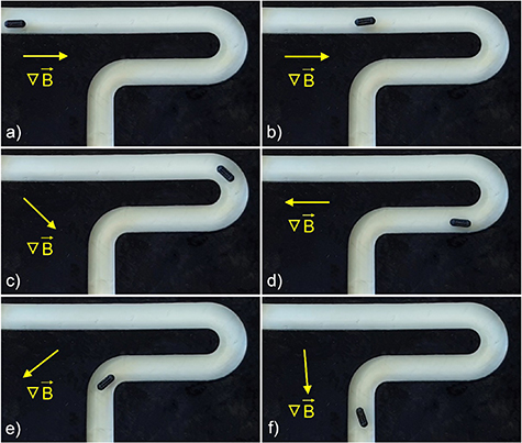
Figure 5. Gradient actuation of a B-NN device inside a serpentine channel; the direction of the magnetic field is evidenced in each frame (from (a) to (f)).
Download figure:
Standard image High-resolution image3.5. Drug release
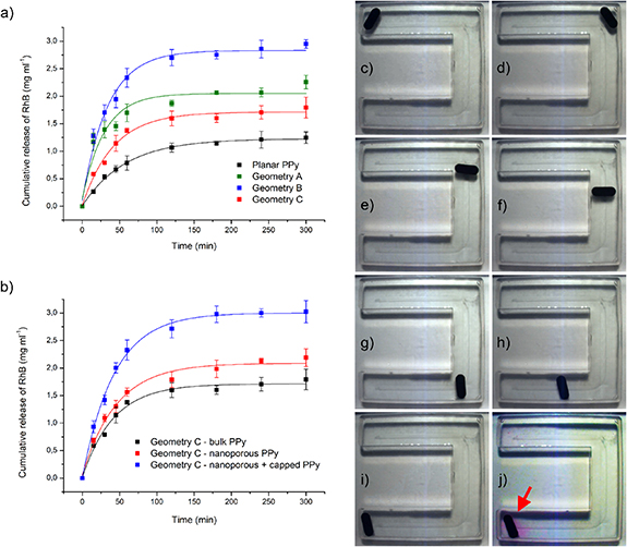
RhB release tests were performed on all the devices produced to investigate their drug release performances. Released RhB was quantified as a function of release time. Initially, the influence of devices geometry was evaluated and compared with a planar PPy layer (1 cm2 area). Figure 6(a) depicts the result obtained for the following samples: A-NN, B-NN, C-NN. It can be immediately noticed that the total amount of released RhB at constant time strongly depends on the geometry of the device employed. This is a clear consequence of the different surfaces of the devices. By normalizing with respect to the area, all the curves reported in figure 6(a) tends to superimpose (figure S7). This demonstrates that the total amount of RhB stored in the devices and subsequently released during the tests depends only on the total area of the devices. Consequently, microstructured geometries are highly advantageous to increase the quantity of transported drug, which can be tuned by modifying the morphology of the device.
Figure 6. Release data and corresponding fitted curves for NN samples characterized by different geometries (a); release data and fitted curves for C geometry samples characterized by different levels of nanostructuring (b); actuation and drug release of a A-NN sample inside a C-shaped channel (from (c) to (j)).
Download figure:
Standard image High-resolution image
Other important considerations can be done on the shape of the release curves, which is indicative of the kinetics of the release mechanism. Drug release can be modeled according to a wealth of mathematical models [68]. In the case of PPy, however, this methodology has been poorly implemented in the existing literature. The reason resides probably in the peculiar characteristics of the layers obtained from electrodeposition, which is the technique used to deposit many PPy coatings described in literature. According to the parameters employed, electrodeposited PPy layers may present a varying degree of porosity [26]. Moreover, electrodeposited layers are often internally stressed. All these effects influence release kinetics and make difficult applying mathematical models to interpret drug release.
Following already consolidated approaches [26, 39, 69, 70], drug release can be conveniently modeled with a simple exponential law (equation (6)).

r represents the released amount of RhB at time t. r0 is the release at infinite time, which is indicative of the terminal released amount of RhB. R0 represents the exponential release rate of the layer, while A is a constant. Figure 6(a) reports the fitting operated on the experimental data employing equation (6), while table 2 summarizes the fitting parameters.
Table 2. Fitting parameters for the experimental data presented in figure 6.
| r0 (mg ml−1) | A (mg ml−1) | R0 (s−1) | |
|---|---|---|---|
| Planar PPy | 1.227 | −1.224 | −0.017 |
| A-NN | 2.051 | −1.929 | −0.034 |
| B-NN | 2.832 | −2.734 | −0.029 |
| C-NN | 1.713 | −1.701 | −0.024 |
| C-NA | 2.087 | −2.031 | −0.022 |
| C-NA + capping | 3.002 | −2.995 | −0.023 |
r0 values confirm the trend observed: different geometries are characterized by different terminal released amounts. Moreover, a difference in release rate R0 can be observed between planar PPy samples and the devices. In general, the devices are characterized by higher release rates. Such different release rates realistically depend on the curvature of the devices, which translates into different distribution of internal stresses inside the deposit. Moreover, the different growth rates resulting from the uneven electric field distribution may potentially result in different degrees of porosity of the PPy layer in different zones of the samples. It is important to point out that the presence of internal stresses during drug release from polymeric layers is contemplated in some mathematical models, like the Peppas–Sahlin one [68].
Figure 6(b) reports the release data obtained in the case of a C-NA sample, which is compared with the corresponding C-NN sample. Interestingly, it can be noticed that nanostructuring alone is almost ineffective in increasing the amount of released drug. In analogy with our previous work [39], nanostructuring significantly increases drug loading only when coupled with a PPy capping layer deposited on top of the NA layer. For this reason, a C-NA sample was coated with a capping layer (deposited at 10 mA cm−2 for 30 s) and the release test was repeated. As visible in figure 6(a) and table 2, which reports the corresponding fitting parameters, the release kinetic of the capped C-NA sample is analogous to the C-NN device. The same is not true in the case of terminal released amount of RhB (r0), which increased from 1.713 mg ml−1 to 3.002 mg ml−1. The final effect was a 75.25% increase in the total amount of released drug at long times.
To demonstrate the drug release capabilities of the devices described in the present work, a A-NN sample was loaded with RhB and placed in the same C-shaped channel (whose dimensions are detailed in figure S6) employed in the supporting video 3. It was wirelessly guided (figures 6(c)–(i)) to the end of the channel (which was assumed as target zone) and left there for 60 min. As visible in figure 6(j), the zone in close proximity with the device colored, indicating the release of RhB in the target zone (supporting video 5).
Finally, it is fundamental to emphasize that also pH plays a role on drug release performances of the devices. This is especially true in the case of a potential use in the gastrointestinal system, where the device would encounter environments characterized by radically different pH values (from 1.5 in the stomach to 8.5 in the colon). The present work makes use of a model molecule to conceptually show the delivery route in water (pH ∼ 7). For this reason, effect of pH on RhB release from PPy was not studied. In the case of real applications, involving pharmacoactive molecules, it is fundamental to evaluate drug release as a function of external pH. The pH related delivery behavior largely depends on the specific molecule employed, but also PPy itself can potentially determine the release rate. Pernaut et al [71] demonstrated that high pH levels (>9) favor PPy deprotonation, resulting in high release rates for the adenosine triphosphate molecules loaded in their PPy layer. Such pH levels, however, are normally not found inside human body. In front of this consideration, the main contribution to pH-dependent drug release realistically comes from the molecule employed to load PPy.
3.6. Biocompatibility
To complete the functional characterization of the devices, their biocompatibility was assessed. In particular, the analysis was focused on quantifying the unwanted release of toxic species from the samples. Biocompatibility of PPy, which constitutes the top layer for the devices, has been clearly demonstrated [28]. The only source of concern from this point of view may be the SBDS employed as dopant during PPy deposition. SBDS, however, is known to be toxic only at high concentrations [72]. Moreover, the BDS ion is immobilized inside the PPy coating, due to its consistent sterical dimension. As a consequence, only sodium counterions are relatively free to move, as demonstrated by the electrochemical characterization performed on SBDS doped PPy layers [39].
The internal structure of the devices, nevertheless, is characterized by the presence of Ni, Cu and Co, which are transition metals potentially harmful in high concentrations. Ni and Co, in particular, have been demonstrated to have a highly teratogenic effect on human cells [73, 74]. Consequently, pollutants release tests were performed immersing three samples in PBS for 2 d and analyzing the resultant solution. PBS was used as solution due to its high dissolved salts concentration, which allow a realistic testing for pollutants release. ICP showed the presence of trace amounts of Ni and Co, with concentrations below the limit of the detection range. In quantitative terms, the solution contained very low concentrations for the two metals (≪0.05 mg l−1). These values are, for example, well below the limits for drinkable water defined by the Worlds Health Organization [75].
Analogously to drug release, pH may have an effect also on biocompatibility. Devices were tested in PBS (pH 7.4) and no release of toxic metals was detected. Chemical stability is expectable also at high pH, where the transition metals employed readily passivate. However, release may still potentially take place at low pH, where Co, Ni and Cu can be oxidized to water soluble cations. In light of this consideration, it is useful to highlight that the device is coated with a Pt layer, which offers a high chemical resistance in acidic environments. Furthermore, also PPy is highly inert at low pH, as demonstrated by its use as corrosion protection layer [76]. Due to the presence of Pt and PPy, the devices produced in the present work are characterized by a good chemical resistance.
4. Conclusions
In the present work, magnetically steerable devices for drug delivery were successfully fabricated by combining for the first time 3D printing and wet metallization. The possibility to apply functional layers on the stereolithography printed devices by electrolytic deposition was demonstrated. Thanks to the intrinsic scalability of the electrodeposition technique, conformal coatings were deposited on many devices at the same time, allowing potential scale-up for efficient high volume production. At the end of the deposition process, PPy was deposited as drug releasing layer, both in bulk and NA form. Drug release tests carried out on finished samples highlighted a clear dependence of the total amount of release drug on the shape of the device. In the case of NA PPy-coated devices, a 75.25% increase in total releasable drug with respect to NN PPy was found. This data clearly demonstrate that NA PPy, applied here for the first time on a magnetically moveable microdevice, possesses a considerable potential to enhance drug delivery performances of untethered drug delivery devices. Magnetic maneuverability was assessed by performing dedicated tests, which evidenced a precise and reproducible remote control with both rolling and gradient actuation. The microrobots obtained in the present work may find potential application in the digestive apparatus. A notable target application, due to the region-specific nature of this syndrome, can be the pharmacological treatment of Crohn's disease. In conclusion, the microdevices described are attractive for localized drug administration applications for the therapy of many diseases typical of the gastrointestinal tract.