


Introduction
The deep ice core drilling project at the top of the dome of the East Antarctic ice sheet was started in 1988 by the Working Committee on Deep Ice Core Drilling at the National Institute of Polar Research, Japan. Developments of the deep ice core drilling system were presented in the following papers and reports. The first deep drill development was proposed by Suzuki and Shimbori (Reference Suzuki and Shimbori1986) and high-pressure ice cutting experiments were reported by Narita and others (Reference Narita, Shinbori and Kodama1994). Fujii and others (Reference Fujii1990), Tanaka and others (Reference Tanaka1994), Fujita and others (Reference Fujita1994), Narita and others (Reference Narita1995) and Takahashi and others (Reference Takahashi1996) developed the first deep ice core drilling system, which was planned to be used by the Japanese Antarctic Research Expedition (JARE) at Dome Fuji (77°18′59″S, 39°42′05″E, 3810 m a.s.l.), Antarctica. Takahashi (Reference Takahashi2005) presented a new drill head which allowed for warm ice drilling in the deeper part of the ice sheet. Azuma and others (Reference Azuma, Tanabe and Motoyama2007) described the heat generated by ice cutting during deep drilling. The drilling progress of the first deep ice core at Dome Fuji was reported by Fujii and others (Reference Fujii1999) and Fujii and others (Reference Fujii2001). Saito and Kinoshita (Reference Saito and Kinoshita2005) and Kameda and others (Reference Kameda2005) reported the reopening of the Dome Fuji station, the construction of a new drill site and the installation of the drill systems for the second deep ice core drilling program. The progress of this second deep drilling operation was described by Motoyama (Reference Motoyama2007) and Motoyama and others (Reference Motoyama2020).
As the international deep ice core drilling technologies, Augustin and others (Reference Augustin2007b) reported on warm ice drilling in the deeper part of the ice sheet, Johnsen and others (Reference Johnsen2007) on the Hans Tausen drill developed at the University of Copenhagen and Shturmakov and others (Reference Shturmakov, Lebar and Bentley2014) on the DISC drill developed in the USA, respectively. Talalay (Reference Talalay2014, Reference Talalay2016, Reference Talalay2020) summarized drill heads of the deep ice electromechanical drills, mechanical ice drilling technology and thermal ice drilling technology. Recent deep ice core drilling operations in the Antarctic ice sheet were reported by Augustin and others (Reference Augustin, Panichi and Frascati2007a) on drilling at EPICA Dome C, Zhang and others (Reference Zhang2014) at Dome A, Wilhelms and others (Reference Wilhelms2014) at EPICA-DML, Slawny and others (Reference Slawny2014) and Souney and others (Reference Souney2014) at WAIS Divide and Litvinenko and others (Reference Litvinenko, Vasiliev, Lipenkov, Dmitriev and Podoliak2014) at Vostok, respectively. Popp and others (Reference Popp, Hansen, Sheldon and Panton2014a, Reference Popp, Hansen, Sheldon, Schwander and Johnsonb) reported on the deep ice core drilling at NEEM in Greenland.
The first deep ice core drilling operation at Dome Fuji began in January 1995 and reached a depth of 2503 m in December 1996. However, the drill became stuck in the borehole due to a lowering of the fluid level and the drill could not be recovered for the next four seasons.
The second deep ice core drilling project at Dome Fuji, which aimed to drill from the surface of the ice sheet to the bedrock, began in 2001. Drilling operations were only conducted during the austral summers from 2003/04 to 2006/07. On 23 January 2006, ice core drilling successfully reached a depth of 3028.52 m. A total of 127 drilling days were required to reach this depth, with an average drilling speed of 160 m week−1. The drilled cores were of good quality with little or no cracking. In the fourth season, drilling was conducted in the warm ice at the pressure-melting point near the bedrock. Drilling was very challenging and the obtained ice core was extremely short. Eventually, on 26 January 2007, drilling stopped at a depth of 3035.22 m. When drilling was achieved deeper than 3034.34 m, the ice temperature reached −2.0 °C and water beneath the ice sheet leaked into the borehole and refroze (Figs 1a–c). Small particles, probably of bedrock origin, were found in the ice core (Figs 1d and e). Watanabe and others (Reference Watanabe1999) determined as 3028 ± 15 m to bedrock by ground-penetrating radar observations. For these reasons, the bottom of the borehole was assumed to be close to the bedrock.
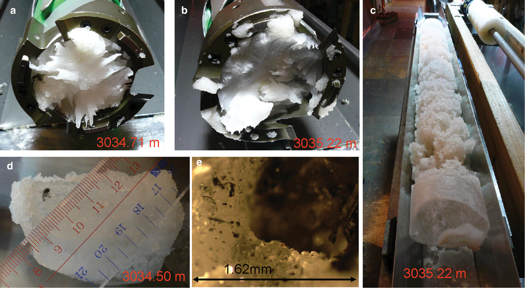
Fig. 1. Drilling of the deepest part of the ice sheet. Refreezing ice of subglacial water on cutter mounts at depths of (a) 3034.71 m and (b) 3035.22 m. (c) 7 cm long ice core and refrozen subglacial water chips on the top of core at a depth of 3035.22 m. Small particle (probably of bedrock origin) in the ice core at a depth of 3034.50 m. (d) Whole picture of the ice core with a particle. (e) Close-up of a part of the particle.
The improved deep drill
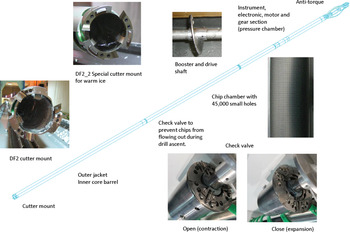
The JARE improved deep drill features (1) a simple design including an ice chip transport mechanism with an Archimedean pump and booster, (2) a chip chamber with a fine screen for stable cutting/screening and (3) check valves to prevent chips from flowing out during the drill ascent (Takahashi and others, Reference Takahashi2001).
Basic concept
The basic concept of the improved deep drill (DF2) is similar to the first JARE deep drill (hereinafter referred to as the DF1 drill; Fujii and others, Reference Fujii1999, Reference Fujii2001). In other words, the cuttings transport system is the same Archimedean pump system (a type of screw pump) as used in the DF1 drill. An Archimedean pump comprises a belt that is spirally wrapped around the surface of the core barrel. When this belt is rotated in the fluid, the spiral picks up the fluid and chips and acts as a pump or screw conveyor to move them upward. This simple mechanism has the advantages of stability and easy handling, which are the most advantageous features of the JARE drills.
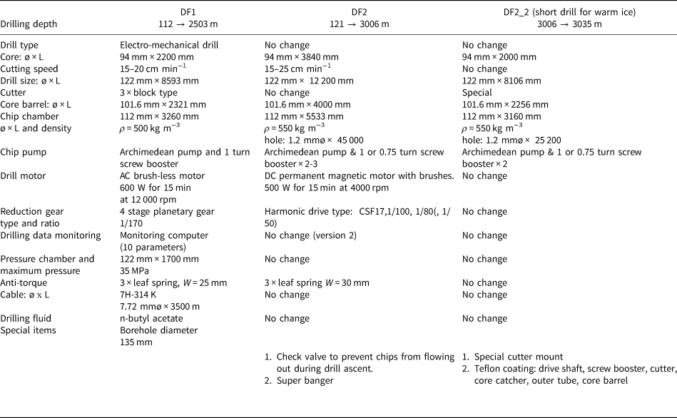
Table 1 summarizes the main characteristics of the DF1 and DF2 drills, as well as the DF2_2 drill fabricated for warm ice drilling in the deeper part of the ice sheet. Figure 2 shows the major improved parts of the DF2 drill. Ice cores with a diameter of 94 mm and a length of 3840 mm can be recovered during a single drilling operation. The deep drilling operations at Dome Fuji station are shown in Figure 3.
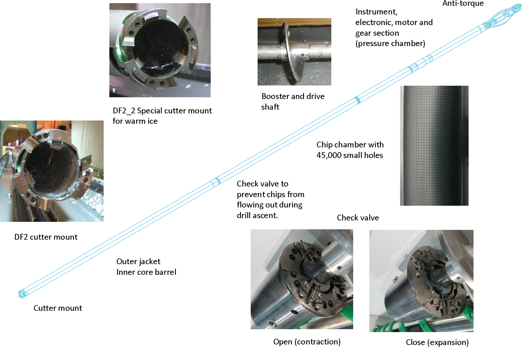
Fig. 2. DF2 drill cutaway mock-up showing major sections of the drill. Full length: 12.2 m; Diameter of pipe: 123 mm.
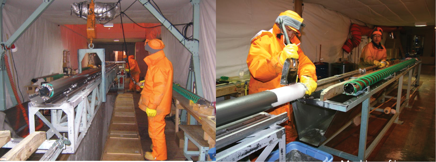
Fig. 3. Deep ice core drilling operation at Dome Fuji station.
Table 1. Specifications of the Japanese Antarctic Research Expedition (JARE) DF1 drill and the improved DF2 drills
Reduction in drilling operation time
Reducing the drilling operation time was the most important concept for designing the improved drill. The maximum length of each ice core is 3.84 m, which reduces the number of drilling operations and the total drilling time. However, a longer core barrel does not always mean that a longer core is obtained. Longer ice cores were made possible by smooth fluid circulation through a screen-type chip chamber with 45 000 small holes.
Reduced breakdown and maintenance with the improved drill
In addition to the extension of the core barrel length, the other major improvement was to the driving section, which consists of a drill motor and a reducer. Other improvements were antitorque features, electrical contacts, seals for the pressure chamber, a check valve to prevent chips from flowing out during drill ascent, super bangers for the stuck drill situations, a cutter mount, and cutters and core catchers with improved materials and shapes (Table 1). As a result of these improvements, both the breakdown rate and the required maintenance time were significantly reduced.
Analysis of deep drilling
Summary of drilling progress
The progress of deep drilling is shown in Table 2, beginning in 2001 when a pilot hole was drilled. As the drilling depth is based on the surface used for the DF1 drilling program, the DF2 drilling depth begins at −1.00 m. The number of drilling days shown in the table does not include the time required for reaming operations in 2001. From the first season to the third season of deep drilling, the average core length was 3.45 m. The drilling progressed very smoothly. In particular, since the maximum core length was 3.84 m, the recovery rate was 84% in the first season, 96% in the second season and 85% in the third season.
Table 2. Progress of deep ice core drilling. Summary of seasonal activity
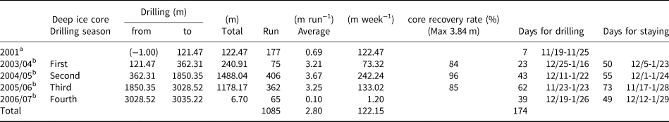
a Shallow drilling for pilot hole.
b Deep ice core drilling.
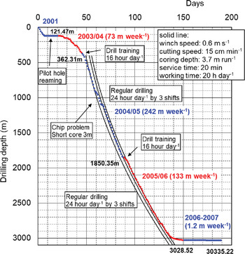
Ultimately, 1085 drilling runs were required to reach a depth of 3035 m. The average length of the ice cores was 2.80 m and the total number of drilling days was 174. The relationship between the number of drilling days and drilling depth is shown in Figure 4. The standard drilling parameters are shown in the upper right of Figure 4 and the drilling speeds calculated for these parameters are shown as solid lines in the same figure. These data indicate that almost perfect drilling without any major problems was achieved in the second and third seasons. Figure 5 shows the drilling length per day as a bar graph. From the second season onward, drilling was carried out throughout the day and the maximum daily core length exceeded 50 m. Although the daily drilling depth was limited by breakdowns and maintenance, we were able to drill ~30 m a day, even at depths exceeding 2000 m.
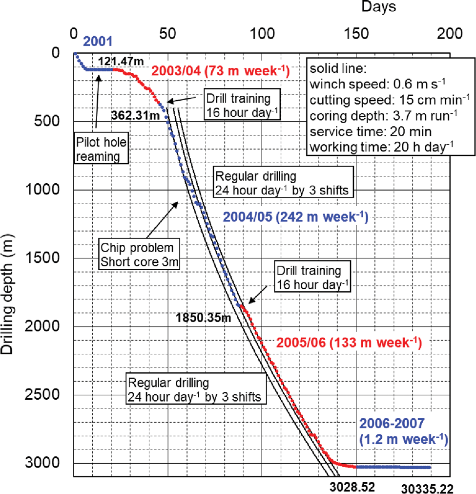
Fig. 4. Daily progress of deep ice core drilling from December 2001 to January 2007.
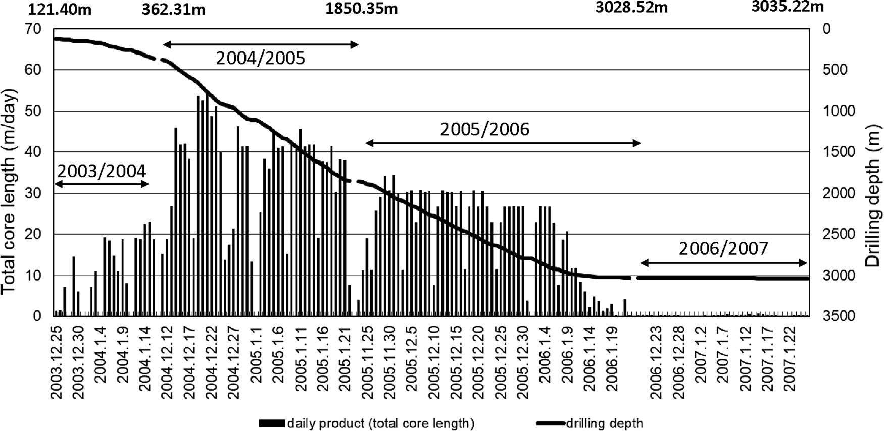
Fig. 5. Daily product of ice core from December 2003 to January 2007.
Drilling information
Selection of the cutter and shoe
Two main types of cutters, with rake angles of 35° and 40°, respectively, were used (Fig. 2). At depths above 1000 m, 35° cutters were used because the ice was very cold and hard. Meanwhile, at depths below 2400 m, when the ice became warmer and softer, 40° cutters were used. At depths between 1000 and 2400 m, both types of cutters were used. The shoes were prepared with a design pitch of 2–5 mm per revolution of the drill head. Because we wanted to make the ice chips larger to facilitate chip transportation and efficient storage in the chip chamber, we mainly used the 4 mm shoes, however, the cutting pitch was reduced according to the drilling conditions.
Selection of the reducer and drill speed
Harmonic drive reducers with reduction ratios of 1/50, 1/80 and 1/100 were prepared. When we started the deep drilling, a 1/50 reducer was used to increase the core barrel rotation speed to ~80 rpm with reference to the conditions of the shallow drilling at 0–200 m. However, a 1/50 reducer could not achieve sufficient torque to cut the cold and hard ice. Therefore, a 1/80 reducer was used for depths up to 2171 m and a 1/100 reducer was used for depths below 2171 m, where the drill motor rotation speed was increased, nearly to the rating of the drill motor.
Current and voltage of the drill motor
Figures 6a and b show the drill motor current and voltage during ice core drilling, respectively. The rated specifications of the drill motor were as follows: direct current of 200 V, power consumption of 500 W and rotation speed of 4000 rpm. In consideration of the allowable motor performance, an alarm was set at 3.7 A and the motor stop was set at 4.2 A. At depths of 150–700 m, the motor current increased monotonically, as shown in Figure 6a. This was because the hardness of the ice increased with depth due to the high pressure of air bubbles in the ice. Between 700 and 2171 m, the motor current fluctuated. In general, a cutter with a rake angle of 40° is more efficient than one with a rake angle of 35° and therefore the current of the drill motor is lower for the latter cutter. From 2171 to 2900 m, the motor current decreased because the harmonic reducer was changed from 1/80 to 1/100 and the ice became softer. At depths below 2900 m, the motor current increased again because of the increasing difficulty of ice chip transportation. Figure 6b shows the supply voltage from the surface to a depth of 1850 m and the voltage actually supplied to the motor at depths below 1850 m. The supply voltage increases monotonically with depth. Between depths of 500 and 2000 m, the core barrel rotation speed and motor current show some variation with no particular trend. The winch cable of the outer covering was used as a ground. When the cable was wound around the winch drum, the grounding of the cable was shorted. When the cable is extended, the cable resistance increases and the longer the cable, the greater the cable resistance. Therefore, it was necessary to increase the supply voltage with depth. At depths below 2200 m, the drill motor was run at 180–190 V, which is close to its rated torque.
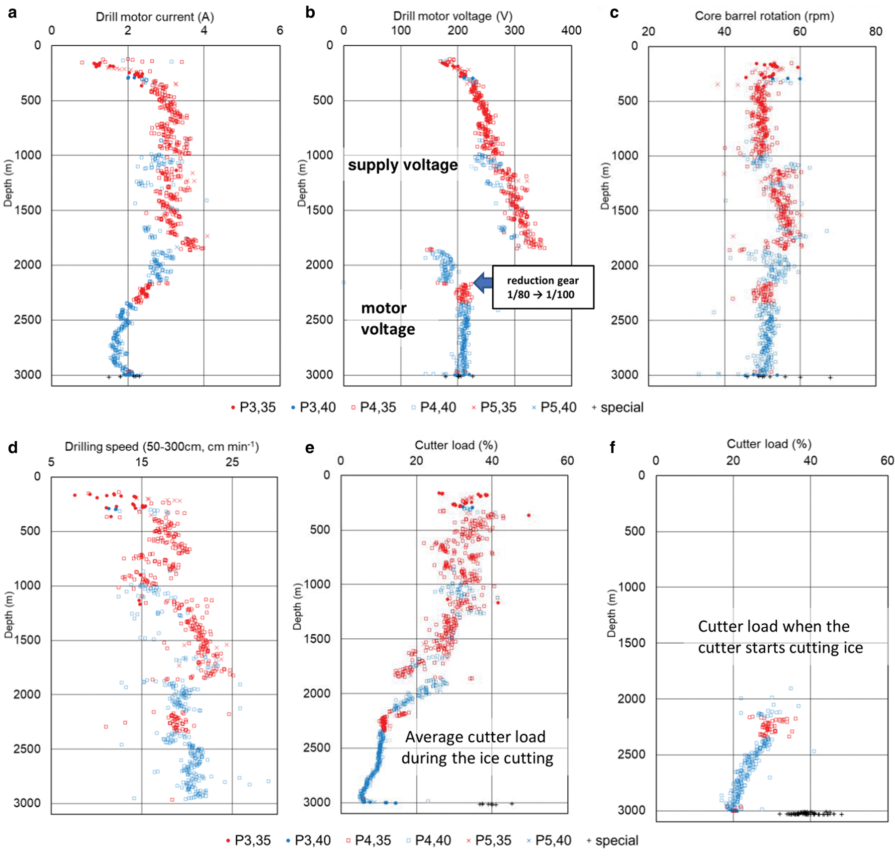
Fig. 6. (a) Average drill motor current during ice core cutting. (b) Drill motor voltage during ice core cutting. (c) Average core barrel rotation. (d) Average cutting speed. (e) Average cutter load during ice cutting. The cutter load is shown as a relative value to the total load. (To convert this to an absolute value of cutter load, it is necessary to multiply it by a drill load.) (f) Cutter load when the cutter starts cutting ice. Symbols and colors indicate the combination of cutter and shoe types. P3: shoe of 3 mm pitch design, P4: shoe of 4 mm pitch design, P5: shoe of 5 mm pitch design, 35: cutter with a rake angle of 35° (red), 40: cutter with a rake angle of 40° (blue), special: special cutter mount for warm ice (black).
Core barrel rotation speed
The core barrel rotation speeds with depth are shown in Figure 6c. Based on trial and error under different drilling conditions, the rotation speed of the core barrel was set at ~50–55 rpm. After reaching a depth of 1000 m, the rotation speed was increased, however, this did not affect the efficiency of drilling. After the reducer was changed from 1/80 to 1/100 at depths below 2171 m, the drilling speed was ~50 rpm with a motor rated at ~200 V.
Drilling speed
The ice core drilling speed at depths of 0.5–3.0 m for each run is shown in Figure 6d. The drilling speed was determined by the rotation speed of the core barrel, the cutting pitch and the winch feeding speed during drilling. At depths below 2500 m, the cutter load was small and ice core drilling was stable and synchronized with winch the fed cable during penetration. The time required for ice core drilling in each run was ~20–30 min.
Cutter load
The cutter load during ice cutting is shown in Figures 6e and f. By monitoring the change in the length of the spring that suspends the drill by the potentiometer, it is possible to determine the cutter load (contact pressure). Here, the cutter load is shown as a relative value to the total load. To convert this to an absolute value of the cutter load, it is necessary to multiply it by a drill load (~150 kg). To eliminate the tilt of the borehole by suspending the drill vertically, the contact pressure should be as low as possible. However, if it is too low, the cutter will not bite into the ice and it will slip. Figure 6e shows the average cutter load during ice cutting. As the ice temperature rises and the ice becomes softer, the cutter load decreases. Note that there is a gap at a depth of 1850 m, which may be due to a change in the zero level of the potentiometer (which measures the length of the spring). Figure 6f shows the cutter load when the cutter starts cutting ice. These values are greater than the cutter load during ice cutting.
Cutting pitch
The measured values of the cutting pitch are shown in Figure 7a. In the first year of deep drilling, design pitches between 3 mm (P3) and 5 mm (P5) were used to determine the optimum conditions for drilling. Finally, P4 was found to be the most suitable. At depths of up to 1500 m, the actual pitch varied from 3 to 4 mm, while below 1500 m in depth stable drilling was achieved with a pitch of almost 4 mm.
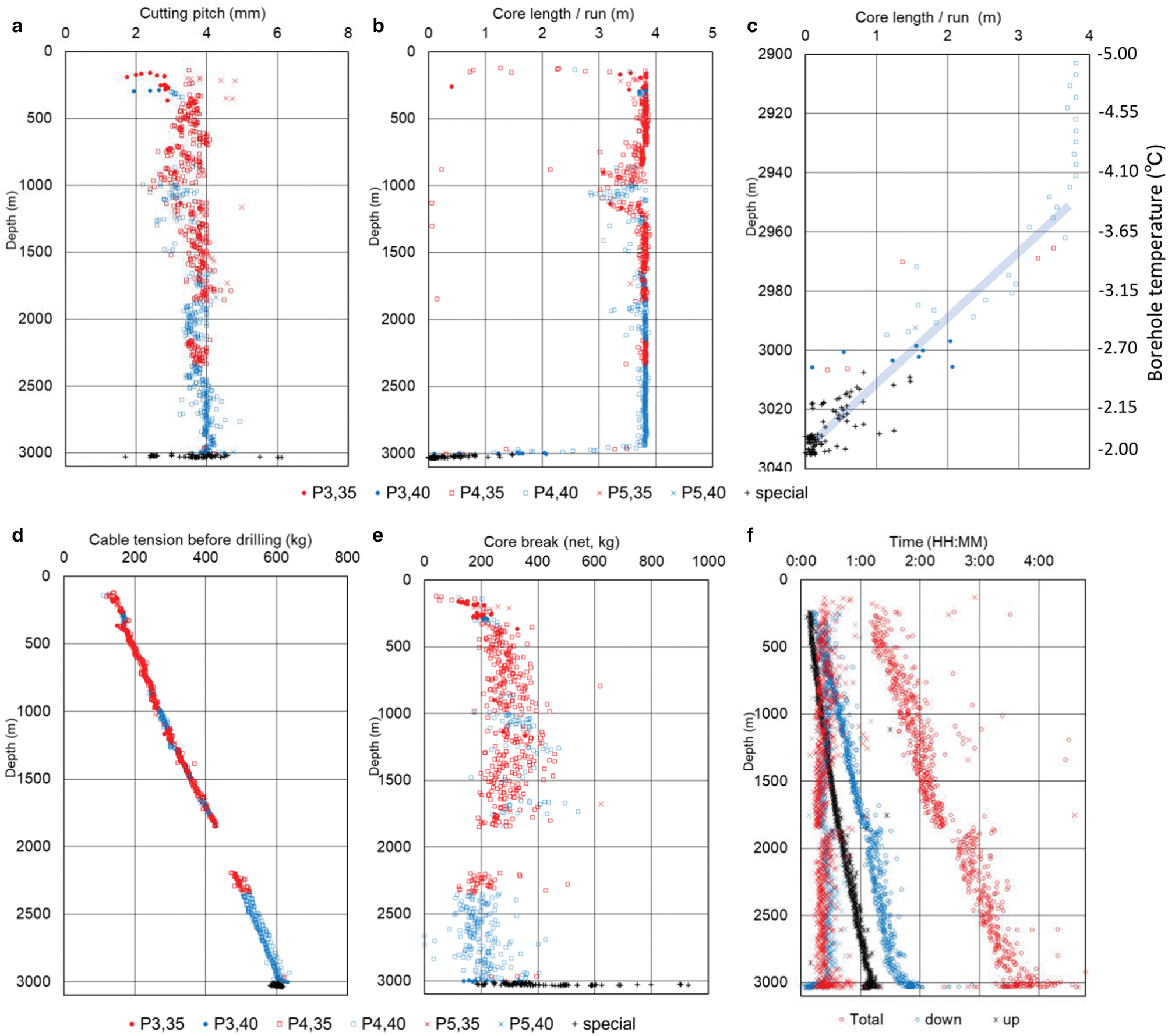
Fig. 7. (a) Measured cutting pitch during ice core drilling. (b) Core length per run. (c) Core length deeper than 2900 m. The fluid temperature in the borehole is also shown. (d) Cable tension before cutting. (e) Tension for net core break. The symbols and colors are the same as in Figure 5. (f) Working time per run. Total: total time for drilling operation; down: time to descend the drill from the surface to the borehole bottom; up: time to ascend the drill from the borehole bottom to the surface; cutting: ice core cutting time; surface: working time on the surface.
Core length per run
The core length per run is shown in Figure 7b. At depths of 800–1200 m, the ice chips did not smoothly enter the chip chamber as at depths below 800 m. Changing the type and mounting position of the booster, as well as the cutting pitch, did not significantly improve this problem. This depth range corresponds to the depth where air bubbles in the ice change to clathrates. This difference in the physical properties of the ice may have caused the difficulty of drilling. At depths below 2950 m, the warm ice temperatures make it difficult to transport the ice chips since they easily become consolidated during chip transport. Figure 7c shows an enlargement of a part of the depth deeper than 2900 m in Figure 7b. At depths >2950 m, the core length reduced linearly with increasing depth. Ice core drilling became challenging at depths >2950 m, where the ice temperature was higher than −4°C. Near the bottom of the ice sheet, the pressure-melting temperature reached −2°C, making it almost impossible to drill.
Cable tension
Figure 7d shows the change of cable tension just above the bottom of the borehole. This tension corresponds to the combined load of the drill and cable within the drill fluid. At the time of the core break, the tension to break the ice core is added to the cable tension.
The net tension of the core break is shown in Figure 7e. This is the tension required for the core break only. At depths of 500–1850 m, the core break tension was 200–400 kg and at depths below 2200 m, it was ~100–300 kg. As depths below 3000 m, the net core break tension was sometimes close to 1 ton because of the breaking of ice single-crystals as large as 1 m. Drill jammed at a depth of 3024 m. After 3 h and 30 min, by applying 1500 kg including the cable (net core break of 900 kg), the core was successfully cut; however, the ice core was deformed.
Remaining ice chips on top of the core
When the ice core is removed from the core barrel at the surface, there are sometimes ice chips on top of the core. However, it is preferable to have no ice chips being present because the maximum core length is shortened by the thickness of the chips cake. At depths above 3000 m, some chips remained on top of the core for no obvious reason. At depths below 3000 m, there was a large amount of chips on top of the core, probably due to the refreezing of subglacial water.
Drill descent time and descent speed
The drill was descended into the borehole almost in freefall. The cutter load was carefully monitored to determine if there was any slack in the cable. It took nearly 2 hours to descend the drill to a depth of 3000 m. The average drill descent speed ranged from 0.4 to 0.5 m s−1.
Drill ascent time and ascent speed
The drill ascent speed to the surface depends on the ability of the winch. The speed of the winch motor was adjusted while ensuring that the cable tension did not exceed 900 kg. As the diameter of the winch drum gradually increases during drill ascent, the drill ascent speed gradually increases at the same winch motor speed. The maximum drill ascent speed was set at 0.8–0.9 m s−1.
Surface work
The working time when a drill was at the surface was ~15–30 min. If the cutting chips fit uniformly into the chip chamber and the ice core was obtained as a coherent piece (i.e., without breaking), the surface work was completed in <15 min.
Total work time per run
Figure 7f summarizes the total work time per run. Drilling a core at a depth of 3000 m or more takes nearly 4 h. The factors affecting this time are as follows: time to descend the drill from the surface to the borehole bottom; ice core drilling time; time to ascend the drill from the borehole bottom to the surface; and time spent working at the surface. Each of these components is shown in Figure 7f.
Borehole condition
Figure 8a shows the 10 m average inclination of the borehole measured by an inclinometer installed in a drill or a borehole logging system. The borehole was found to be almost vertical to a depth of 2000 m, below which the inclination increased, peaking at 2370 m with a slope of 3.7° and reducing to an inclination of 3° by 2500 m. Below 2500 m, it showed a peak slope of 6° until 2860 m and then returned to a 5° slope at 3000 m. Inclination records of the DF1 borehole show similar changes in inclination to a depth of 2500 m. Depending on the structure of the ice sheet, drilling will proceed more easily in a particular direction.
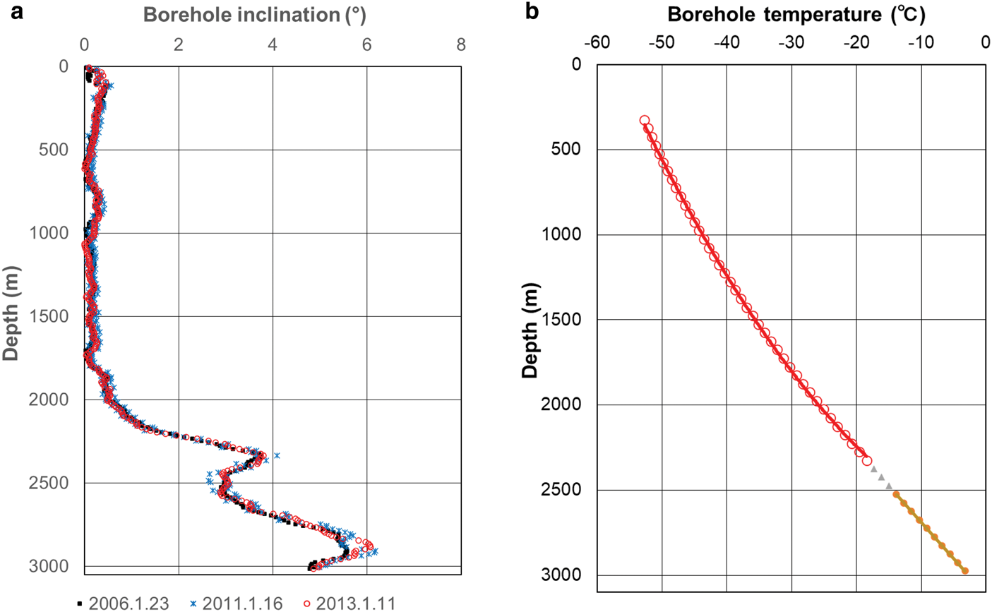
Fig. 8. (a) Borehole inclinations (10 m average) on 23 January 2006, 16 January 2011 and 11 January 2013. (b) Borehole temperature (50 m average) on 11 January 2013.
Figure 8b shows the 50 m average temperature of the borehole fluid measured with a logging system. The relationship between depth and temperature can be approximated by a quadratic equation for depths up to 2300 m and by a linear equation for depths beyond 2500 m. If y is the depth (m) and x is the borehole temperature (°C), the following approximations are obtained:
Ice chip recovery
Almost all ice chips generated during the ice core cutting were stored in a chip chamber. Therefore, only a few chips were left in the borehole fluid. The total weight of chips obtained through chip recovery operations was 110 kg. Figure 9 shows the estimated amount of chips remaining in the hole after each drilling run and the total amount of drill-recovered chips per run. The amount of chips recovered by the drill during ice core drilling was compared with the calculated amount of chips and the difference was small.
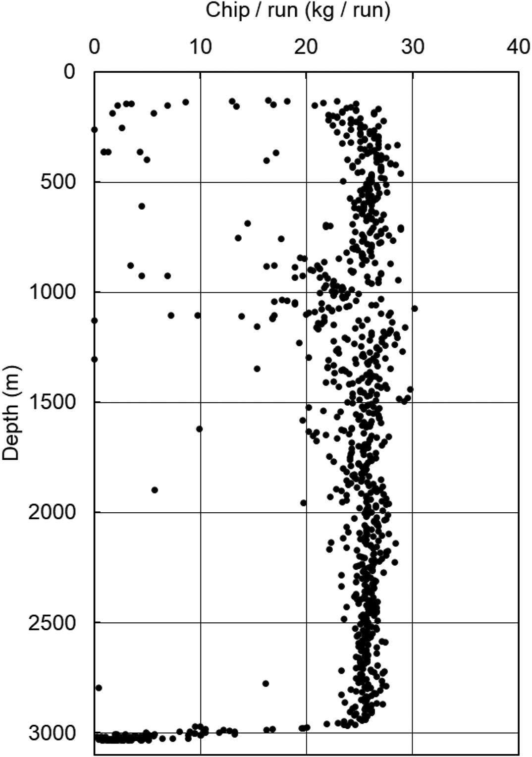
Fig. 9. The weight of chips per run.
The drilling fluid content in the drill-recovered chips after extraction was 15% for the first season, 10% for the second season and 5% for the third and fourth seasons. After the second season, the fluid content decreased. This was due to longer drilling intervals at deeper drilling depths, which allow for longer extraction time. On average, 25 kg of chips were stored inside the drill and recovered to the surface (Fig. 9). The amount of chips remaining in the borehole is within the range of the calculation error. However, at depths >3000 m, more chips were recovered than were produced by ice cutting. This was due to the leakage of subglacial water into the borehole and subsequent refreezing (Figure 1c).
Adding drilling fluid and recovering drilling fluid from chips and cable
Drilling fluid
The drilling fluid (butyl acetate) was added to the borehole in 200 L portions to maintain the level of the fluid at a depth of ~130 m from the surface. The fluid collected from cutting chips and cable at the surface was returned to the borehole. The total volume of fluid added was ~276 drums (55 280 L) and the total volume of fluid in the borehole at the end of the drilling operation was 41 560 L. That is, ~25% of the drilling fluid was lost.
Recovery of drilling fluid from chips and cable
The drilling fluid contained in ice chips was extracted and reused. During drill retrieval, the cable is pulled up to the surface with drilling fluid adhering to the surface of the cable. This drilling fluid drips from the sheave and around the winch. It also causes odor in the drilling site. Therefore, a blanket was wrapped around the cable at the drilling trench floor to stop fluid falling to the floor and winch and to return it to the borehole. A brush and drain were placed between the mast and winch to collect the fluid. When the drill was pulled up to the surface, the fluid adhering to the drill automatically poured into the drain of the drill pit leading to the borehole.
Monitoring of ice core drilling
Various parameters were monitored and recorded during ice core drilling. These parameters illustrated in Figure 10, include drilling depth (black), drill motor current (red), cutter load (green), core barrel rotation speed (blue), motor power consumption (purple) and ground supply voltage (brown).
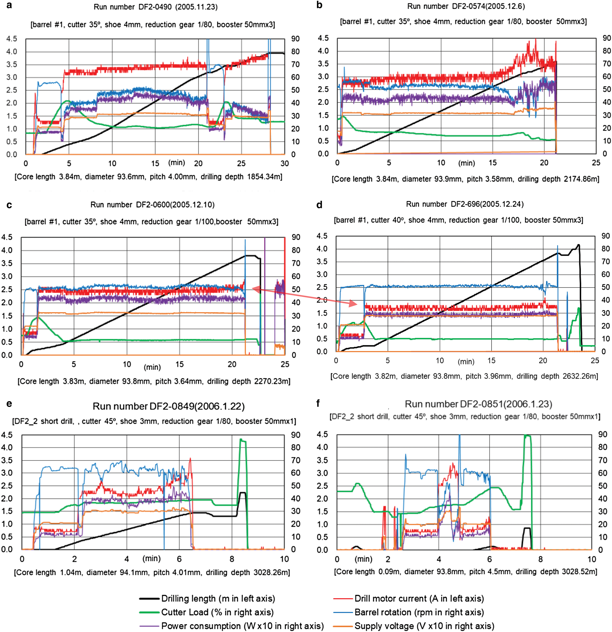
Fig. 10. Example of ice core drilling record. The time series of six items related to the drilling is shown. (a) First drilling of third season. (b) Drilling with an abnormally high drill motor current. (c) Cutter rake angle of 35°. (d) Cutter rake angle of 40°. (e) and (f) Short drill used for warm ice.
The procedure for ice core drilling is described as follows. Each drill run began in the same way: The drill was stopped at a distance of 5–10 cm above the bottom of the borehole. The drill motor was switched on and the core barrel rotation speed was set to 50–60 rpm. Next, the drill was slowly lowered. The cutter load gradually increases as the blade of the cutter lands on the ice and the cutter load decreases as ice cutting begins. Ice core cutting starts. At this time, the motor current rises and the barrel rotation speed decreases, so the supply voltage to the drill motor is adjusted. During ice core cutting, the cable-feeding speed is adjusted to keep the cutter load stable. If the settings are appropriate, there is no need to make any adjustments hereafter. As the cutting chips fill in the chip chamber and the space around the core barrel, the motor current gradually increases. The decision to stop drilling is made when the motor current exceeds 3 A, since this indicates that the chip chamber is almost full or when the motor current drops, as this indicates that the core barrel is full. When ice core cutting is complete, the drill motor is switched off and the drill is slowly raised until the cutter load returns to the initial value. The final depth is checked and the drill motor is briefly reversed to close the check valve. Then, the drill is pulled up at a high speed to cut the core and is allowed to rise. If core cutting is difficult, this is repeated several times.
First drill run of the third season
As an example of the drilling operation, details of the first ice core drilling run from the third season are shown in Figure 10a. Since it was the first run of the season, we were careful to set the initial core barrel rotation speed to 40 rpm. This was then increased to 50 rpm. The winch feeding speed was adjusted so that the cutter load was ~20%. After 21 min, the blade of the cutter slipped, possibly because the winch feeding was too slow. The motor current gradually increased and the rotation of the core barrel decreased, however, the drilling continued. Finally, when the core barrel was full of core, the cutter slipped again. The retrieved core length was 3.84 m.
Drilling with abnormally high drill motor current
Ice cutting with an abnormally high drill motor current is shown in Figure 10b. Ice core cutting progressed smoothly with a motor current of ~3 A. The increase of motor current after 15 min from the start of cutting was due to problems in the transportation and/or the complete filling of the chip chamber with cutting chips. The supply voltage to the motor was increased because the barrel rotation speed was reduced. Finally, the core barrel was completely filled with core, and the cutter slipped, so drilling was completed. The overall cutter load was low at ~15%. However, when the drill computer was inspected at the surface, it was found that part of the circuit had been burned because of the too high current. The retrieved core length was 3.84 m.
Difference between cutter rake angles of 35° and 40°
Ice cores drilled with different cutter rake angles are presented in Figures 10c and d. Figure 10c shows a core drilled with a rake angle of 35°, while Figure 10d depicts a core obtained with a rake angle of 40°. The rotational speed of the core barrel was 50 rpm and the cutter load was ~10%. For a rake angle of 35°, the drilling was efficient at 2.5 A and the power consumption was 450 W. With a rake angle of 40°, the drilling was efficient at 1.7 A and 300 W. However, the surface conditions of the ice cores were different with these different rake angles, being mirror-like at 35° and frosted at 40°.
The chips around the core barrel tend to fall off when the drill rises and chips spill near the bottom of the borehole. Therefore, the core barrel was rotated after the ice core cutting, as shown in Figure 10c. As shown in Figure 10d, after the ice core cutting was completed, the cutter load was increased by lowering the drill. This was because the final depth was defined as the depth with the same cutter load as at the beginning of the drilling.
Short drill for warm ice
The specifications of the short drill used for the warm ice are listed in Table 1. After the first bite of the cutter, the motor current gradually increased (Fig. 10e). Four minutes later, the current jumped to 3.5 A and drilling was terminated. The core cut was normal and a 104 cm long ice core was obtained.
In the last run of the third season, we were able to obtain a core as short as 9 cm, however, the drilling was terminated because the cutter kept slipping (Fig. 10f). Occasionally, the cutter bit the ice and then the current value would rise sharply before immediately falling again and the cutter would slip. This process was attempted several times, however, we decided to abandon and finish the drilling and the core was cut. Obstacles to chip transport and chip hardening/icing may prevent core drilling. The ice core cutting time was <1 min.
Conclusions
The improved JARE deep ice core drill has allowed for significant progress in the second deep ice coring project in terms of core length, time reduction due to faster drilling and stability. The main contributor to this achievement is the addition of a screen with 45 000 small holes to the chip storage chamber. This idea was also adopted for deep ice core drilling at NEEM, Greenland and the South Pole ice core project. The main features of the JARE deep drill are: (1) the core barrel (Archimedean pump); (2) several boosters attached to the shaft of the chip chamber; and (3) a screen consisting of 45 000 small holes in the chip chamber. It is hoped that further research will be conducted on the basis of this research and that deep ice core projects will evolve.
Supplementary material
The supplementary material for this article can be found at https://doi.org/10.1017/aog.2020.84.
Acknowledgements
Drilling development was carried out under the leadership of the Committee on Deep Ice Core Drilling of the second Dome Fuji Project. The state-of-the-art drill is a result of the excellent technology and ideas of the Institute of Low Temperature Science, Hokkaido University, Geo Tecs Co. Ltd, Kyushu Olympia Kogyo Co. Ltd, Geosystems Inc., Oh'TEC Electronics, Nihon Shinkan Co. Ltd., and Toyo Knife Co. Ltd. As for the development of deep ice core drilling, participation in international deep drilling projects such as NorthGRIP and NEEM in Greenland, drilling at EPICA-Dome and EPICA-Kornen in Antarctica, and drilling experiments with a drilling tower in cooperation with the Rikubetsu Technical Research Institute, Hokkaido, Japan, have formed the basis of deep drilling technology at Dome Fuji. The deep drilling at Dome Fuji was strongly supported by many members of the Japanese Antarctic Research Expedition, including inland transportation and base setting.
Author contributions
All authors contributed to drill development. The second Dome Fuji deep ice coring was mainly carried out by H. M., Y. T., K. S., M. M., T. Y., A. F. and H. M., A. T., Y. F. wrote most of the paper draft.


 Open access