


1 Introduction
The application of chirped-pulse amplification (CPA) in solid lasers has realized the output of lasers with femtosecond duration and petawatt-class power[Reference Strickland and Mourou1, Reference Mourou, Fisch, Malkin, Toroker, Khazanov, Sergeev, Tajima and Le Garrec2]. Interaction of such ultra-intense laser pulses with thin foils has generated protons up to 100 MeV and carbon ions close to 600 MeV (see Refs. [3–10]), which has potential applications in the fields of hadron therapy, fast-ignition laser fusion, isotope production, and proton radiography[11–14]. In particular, when the thicknesses of the foils are in the range of several nanometers to a few tens of nanometers, quasi-monoenergetic ions can be generated in the scheme of radiation pressure acceleration (RPA)[15–17]. When ultrathin targets are used, the damage caused by the prepulse energy should be avoided. For a high-power laser pulse with a contrast of 107–109 and intensity of ~1020 W/cm2, the prepulse intensity of amplified spontaneous emission (ASE) or prepulses is in the range of 1011–1013 W/cm2, which is high enough to damage many targets and significantly influence the acceleration process[18–20]. For the upcoming 10 PW class laser facilities such as ELI[Reference Balabanski, Popescu, Stutman, Tanaka, Tesileanu, Ursesc and Zamfir21, Reference Gales, Tanaka, Balabanski, Negoita and Zamfir22], the prepulse intensity will scale up with the increasing peak power. Hence, the choice of target material that can survive the prepulse energy would be a crucial issue for laser-driven ion acceleration.
Ultrathin free-standing foils made of different materials, such as metal, graphite, diamond-like carbon (DLC), and transparent polymers, have been employed as targets in laser ion acceleration experiments for years. Kim et al. reported the generation of 93 MeV protons by using 15 nm formvar, a kind of transparent polymer, as targets irradiated by a PW laser [3]. Prencipe et al. reviewed the ultrathin targets used for ion acceleration and the corresponding fabrication techniques, emphasizing that ultrahigh laser contrast is a pre-requisite for this application[Reference Prencipe, Fuchs, Pascarelli, Schumacher and Cowan23]. The contrast of the laser pulses in many cases imposes a substantial restriction on the choice of targets. Therefore, the laser-induced damage thresholds (LIDTs) of the ultrathin targets are essential parameters that should be learned before the acceleration experiments. In general, LIDTs of the ultrathin foils are considered the same as that of corresponding bulk materials. In fact, they could be significantly different. For nanometer-thin metal foils, their thicknesses are much smaller than their heat deposition depths. The mean energy density in the foils could be significantly higher than that in corresponding bulk materials. For ultrathin dielectric foils, the existence of massive surface defects induces surface states within the bandgap and intrinsic seed carriers, which will affect the ionization and laser energy transport. It is found that, owing to the existence of the surface deffects, the LIDTs of 5–40 nm DLC foils are significantly smaller than that of bulk DLC[Reference Wang, Ma, Bin, Alinger, Shou, Wang, Liu, Zhu, Cao, Mei, Wang, Lu, Lin, Zhao, Schreiber and Yan24]. In addition to DLC foils, systematic studies on the single-shot LIDTs of other types of free-standing ultrathin targets were still missing.
We present a study on the single-shot LIDTs of multi-type free-standing ultrathin foils for a laser pulse with wavelength of 800 nm and pulse durations from 50 fs to 200 ps. Widely used targets made of formvar, silicon nitride (SiN), aluminum (Al), amorphous carbon (a-C), and carbon nanotubes (CNTs) were tested. Our results show that the laser damage threshold fluences (DTFs) of all the ultrathin foils are significantly lower than that of corresponding bulk materials. Formvar and SiN foils have the highest DTF among the tested targets. Their DTFs scale up with the laser pulse duration. For Al, a-C, and CNT foils, the DTFs are weekly dependent on pulse duration in general. By comparing the damage intensity of the targets with the prepulse intensity of a laser system, the constraint of targets’ LIDTs on the laser contrast can be obtained in a simple way.
2 Experimental setup
The experiments were performed on 100s TW Ti:sapphire laser systems of CLAPA in Peking University and on ATLAS in Max-Planck-Institutfür Quantum Optik. Seed pulses from a Kerr-lens mode-locking oscillator were amplified in a linear regenerative amplifier followed by a booster amplifier. The laser pulses were focused onto the samples by an f/3.5 off-axis parabola (OAP) mirror, which was used to generate energetic ions or X-ray/γ-ray emission in other experiments[ Reference Shou, Wang, Wang, Liu, Cao, Mei, Geng, Zhu, Liao, Zhao, Zhu, Lin, Lu, Ma and Yan25]. The full width at half maximum (FWHM) diameter of the focal spot is 4.5 μm, which is measured by a microscopic imaging system equipped with a 12-bit charge-coupled device (CCD). The laser energy was controlled by using different neutral density optical filters before the compressor. All the filters were thinner than 2 mm, avoiding the effects of self-phase modulation and wavefront distortions. A pyroelectric detector PE50 (OPHIR) was used to measure the energy and calibrate the filters. The root mean square (RMS) energy stability of the laser system was typically less than 2%, and we report the average value here. The pulse duration, ranging from 50 fs to 5 ps, was adjusted by moving the diffraction grating in the compressor chamber and measured by a dispersion-minimized autocorrelator (Amplitude). Pulses with durations of 200 ps were obtained by bypassing the compressor.
The foils were positioned precisely at the focal spot controlled by a high-precision position system. After each shot, the foils were front illuminated by a collimated light source. A long working-distance microscope objective lens was driven in behind the foils to image the irradiated foils. The images were recorded by the CCD behind the lens with a high resolution[Reference Shou, Wang, Wang, Liu, Cao, Mei, Geng, Zhu, Liao, Zhao, Zhu, Lin, Lu, Ma and Yan25]. The damaged area of the foils is defined by the permanent holes induced by the laser pulses on the targets. The smallest damage spot we could resolve was approximately 0.5 μm. All the measurements were performed in vacuum environment with the pressure of 3×10⁻³ Pa.
3 Methods and results
The LIDTs of 50 nm formvar, SiN, Al, a-C foils, and 50 μm free-standing CNT foams were measured in the experiments. They were fabricated by the methods of spin-coating (formvar), plasma-enhanced chemical vapor deposition (SiN), thermal deposition (Al, a-C), and chemical vapor deposition (CNT), respectively[Reference Prencipe, Fuchs, Pascarelli, Schumacher and Cowan23, Reference Szeryop, Ma, Bothmann, Hahner, Haug, Hilz, Kreuzer, Lange, Seuferling, Speicher, stehr, Stork, Thirolf, Schreiber and Wirth26]. The CNT targets were used as near-critical-density targets in previous studies[Reference Henig, Steinke, Schnürer, Sokollik, Hörlein, Kiefer, Jung, Schreiber, Hegelich, Yan, Meyer-ter-Vehn, Tajima, Nickles, Sandner and Habs7, Reference Wagner, Deppert, Brabetz, Fiala, Kleinschmidt and Poth10]. Their average density here is 4.5 mg/cm3. The areal density of a 50 μm CNT target is equal to an 80 nm DLC target.
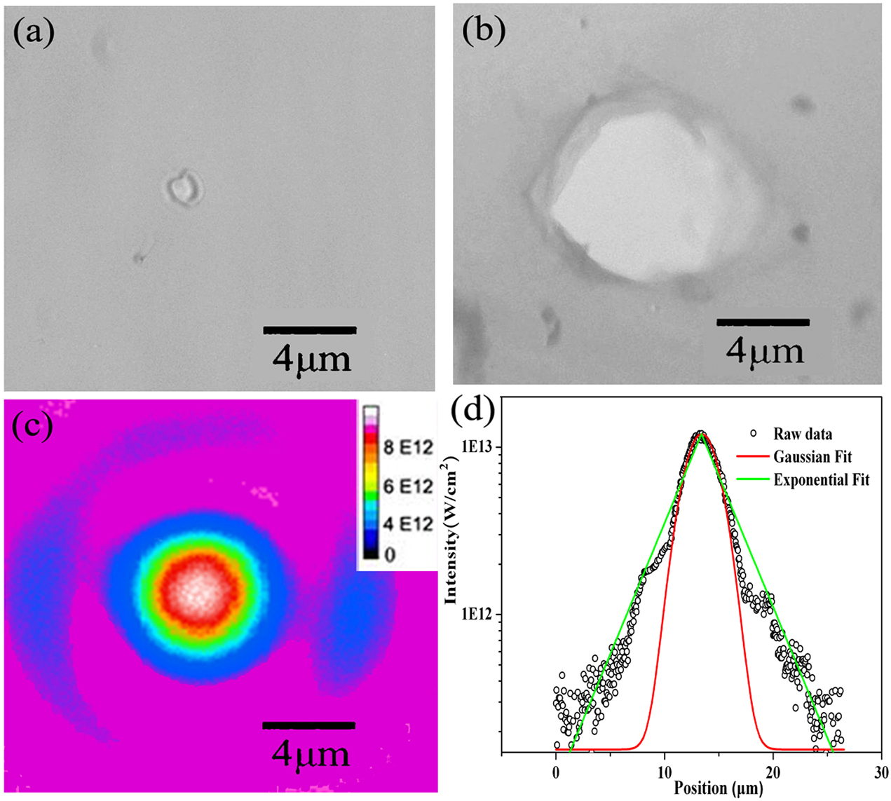
In the experiments, single-shot measurements of the LIDT were performed in order to avoid any incubation or fatigue effects induced by multiple pulses. Figures 1(a) and 1(b) show the damage morphology of a 40 nm formvar foil irradiated by a pulse with FWHM duration of 50 fs at the intensity of 6×10¹² W/cm2 and 1.1×10¹³ W/cm2, respectively. The intensity distribution around the focal spot of the laser is shown in Figure 1(c). The damaged areas of the targets are centered at the peak of the laser pulses, with shapes following the spatial distribution of the laser intensity. It indicates that the damage is intensity-determined. Collateral damage due to thermal diffusion is not dominant.

Figure 1 The damage morphologies of a formvar target under laser irradiation at the intensity of (a) 6×10¹² W/cm2 and (b) 1.1×10¹³ W/cm2. (c) The intensity distribution around the focal spot. (d) A line out of the laser intensity across the focal spot (scattered black circle), the corresponding Gaussian fit (red line), and the exponential fit (green line) of the raw data.
The LIDTs can be obtained by analyzing the damage morphologies at different laser intensity. Figure 2 shows the damage diameter of D with respect to the peak intensity of I. One can see the data can be fit by  $D\propto \ln I$ (see Ref. [Reference Wang, Ma, Bin, Alinger, Shou, Wang, Liu, Zhu, Cao, Mei, Wang, Lu, Lin, Zhao, Schreiber and Yan24]), different from the results of
  ${D}^2\propto \ln I$ when low-power lasers are employed[Reference Krüger and Kautek27, Reference Bonse, Wrobel, Krüger and Kautek28]. This is because, when the focal intensity is much higher than the damage threshold, the diameter of the damaged area is determined by the intensity far away from the focal spot. For 100s TW lasers, the intensity distribution 3DFWHM away from the focal spot typically has an exponential distribution as shown in Figure 1(d) due to the wavefront distortion instead of a Gaussian distribution. Such distortion will not be removed by adding neutral density filters. Thus, the intensity distribution around the focal spot is the same for attenuated beam. By extrapolating the data to
  $D=0$ in Figure 2, we obtain
  ${I}_{\rm th}$=4.5×10¹² W/cm2, which is the single-shot laser damage threshold intensity (DTI) for the 50 nm formvar target at τ=50 fs. Then, the corresponding single-shot DTF F th can be derived as
  ${F}_{\rm th}={I}_{\rm th}\times \tau =$0.18 J/cm2.

Figure 2 Diameter of the damaged area with respect to the laser intensity.
Using the same method, we measured the LIDTs of other ultrathin foils. Figure 3 shows the DTFs with respect to the pulse durations ranging from 50 fs to 200 ps. For a systematic comparison, the result of 40 nm DLC foils obtained in previous study is also included. In general, compared with the DTFs of micrometer-thick foils, the DTFs for these ultrathin foils are smaller by 1–2 orders (see Refs. [28–30]). DTFs of formvar and SiN foils are significantly higher than those of other foils, showing apparent dependence on  $\tau$.

Figure 3 Pulse duration dependence of DTF for formvar (bule diamonds), SiN (green triangles), DLC (black stars), Al (red crosses), a-C (purple squares), and CNT (orange circles).
4 Analysis of damage mechanisms of different targets
According to their conductivity, the targets in this study can be categorized into three categories: formvar and SiN are the insulators, DLC is a semiconductor, whereas Al, a-C, and CNTs are the conductors. For insulators and semiconductors, free electrons/holes are generated through multiphoton absorption and avalanche ionization. Irradiated by the femtosecond laser pulses, damage occurs when the density of free electrons reaches the critical density  ${n}_{\rm cr}$ (
 $=1.1\times {10}^{21}/\lambda^2\ {\mathrm{cm}}^{-3}$). The conductors have free electrons absorbing the laser energy. Damage occurs when the absorbed energy per atom exceeds the bonding energy. Next, we make the analysis of LIDTs results and discuss the damage mechanisms of different targets.
4.1 Formvar and SiN
As shown in Figure 3, DTFs of formvar are higher than that of SiN for all the pulse durations. The dependences of DTFs on the pulse durations for formvar and SiN foils are similar. The DTFs of both foils scale up with  ${\tau}^{1/2}$ (actual fit in our cases:
  ${\tau}^{0.51}$) for
  $\tau$>10 ps. When
  $\tau$<10 ps, the dependence deviates from this scaling.
For long pulses ( $\tau >10\ \hbox{ps}$), as discussed in the previous literature[31–36], the laser intensity is not high enough to initiate an avalanche ionization originating from seed electrons. The damage is due to the fracture or melting caused by the high laser fluence. The rate-limiting process for the rise of temperature is lattice thermal diffusion, and the DTF is proportional to
  ${\tau}^{1/2}$. For pulses shorter than 10 ps, the energy absorbed from the laser field cannot be transferred to the lattice as fast as it is deposited in the electrons. The rate equation of carriers[31–33] can be utilized to analyze the generation and evolution of the free electron density n(t) as follows:
 $$\begin{align}\frac{\hbox{d}n(t)}{\hbox{d}t}=\delta I(t)n(t)+P(I).\end{align}$$
 Here, δ is the avalanche coefficient.  $P(I)={\sigma}_k{\left(I/\mathit{\hbar \omega}\right)}^k{N}_s$ with k the multiphoton order,
  ${\sigma}_k$ the kth absorption cross-section and
  ${N}_s$ the atom density of the foil. If we completely separate the multiphoton and avalanche ionization processes, the DTF can be expressed as
  , where
  ${n}_{\rm cr} (\approx {10}^{21}\,{\rm cm}^{-3})$ is the critical electron density[Reference Stuart, Feit, Herman, Rubenchik, Shore and Perry33],
  ${n}_0$ is the density of the seed electrons for avalanche ionization resulting from multiphoton ionization or defects in the foil. If the number of seed electrons was independent of intensity, e.g., as a result of defects,
 ![]() would be independent of the pulse duration. In the cases of formvar and SiN foil,
would be independent of the pulse duration. In the cases of formvar and SiN foil, ![]() rapidly decreases with pulse duration, which indicates multiphoton ionization plays an important role in the ultrashort pulse limit. In fact, the initial electrons ionized by photons can be calculated as[Reference Stuart, Feit, Rubenchik, Shore and Perry32]
rapidly decreases with pulse duration, which indicates multiphoton ionization plays an important role in the ultrashort pulse limit. In fact, the initial electrons ionized by photons can be calculated as[Reference Stuart, Feit, Rubenchik, Shore and Perry32]
 $$\begin{align}{n}_0&=\int_{{-}\infty}^{{+}\infty}P(I) \hbox{d}t={N}_s\int_{{-}\infty}^{{+}\infty }{\sigma}_k{\left(I/\mathit{\hbar}\omega \right)}^k \hbox{d}t\notag\\&={\sigma}_k{N}_s{\left(I/\mathit{\hbar}\omega \right)}^k{\left(\pi /\ln 2\right)}^{1/2}\tau /k.\end{align}$$
 Set the smallest k to satisfy the equation ![]() , where
, where ![]() ,
,  ${\Delta }_{\rm formvar}=5.5\ \mathrm{eV}$ and
  ${\Delta }_{\rm SiN}=4.5\ \mathrm{eV}$ are the photon energy of the 800 nm laser, the band gap energies of formvar and SiN. We can get the corresponding
  $k$ to be 4 and 3, respectively. Thus, the multiphoton ionization rate scales with intensity as
  ${I}^4$ and
  ${I}^3$ for formvar and SiN. For the laser fluence
  and the Gaussian distribution in the time domain, the DTFs of SiN and formvar under the irradiation of ultrashort pulse are given by

and

One can find a deviation from  ${\tau}^{1/2}$ scaling by Equations (3) and (4). The dashed lines in Figure 3 show the simulated DTF for formvar and SiN by solving Equations (3) and (4). They indicate that the classical model can explain the experimental results.
4.2 DLC
The bandgap of DLC is 3.5 eV, which distinguishes it from formvar and SiN as a semiconductor. The measurement on DLC foils shows that their DTFs are weakly dependent on the pulse duration, which is quite different from formvar and SiN. For ultrathin DLC targets fabricated by cathodic arc deposition, a large number of defects and impurities result in high initial seed electron density (ISED)[37–39]. Owing to the high ISED, avalanche ionization can be easily triggered even without enough contribution from multiphoton ionization. As a result, the DTF is determined by  ${F}_{\rm th}\propto \ln \left(\frac{n_{\rm cr}}{n_0}\right)$, independent of the pulse duration.
4.3 Al, a-C, and CNT
For these three kinds of conductive materials, the values and the dependency on the pulse duration of DTF are similar. For simplicity, we choose Al foils for investigation. Laser energy deposition and transport inside the metal can be described by the two-temperature model[Reference Anisimov, Kapeliovich, Perel'man and Zh40, Reference Corkum, Brunel and Ssherman41]
 $$\begin{align}{C}_e\frac{\partial {T}_e}{\partial t}=\frac{\partial }{\partial x}\kappa \frac{\partial }{\partial x}{T}_e-{g}\left({T}_e-{T}_i\right)+A\left(x,t\right),\end{align}$$
and
 $$\begin{align}{C}_i\frac{\partial }{\partial t}{T}_i=g\left({T}_e-{T}_i\right).\end{align}$$
 Here, the electron heat capacity  ${C}_e$ is given by
  ${C}_e={C_e}^{\prime}\,{T}_e,$ with
  ${C_e}^{\prime }$ being a constant,
  $\kappa$ is the heat conductivity,
  ${T}_e$ and
  ${T}_i$ are the temperatures of the electrons and lattice, respectively,
  ${C}_i$ is the lattice heat capacity,
  $A\left(x,t\right)$ is the source term, and
  $g$ is the electron–photon coupling constant.
Assuming that heat is deposited into the electrons on the surface and neglecting the initial electron temperature, we have the heat deposition depth[Reference Corkum, Brunel and Ssherman41]
 $$\begin{align}{x}_R={\left(\frac{128}{\pi}\right)}^{1/8}{\left(\frac{\kappa_0^2{C}_i}{T_{\rm im}{{g}}^2{C_e}^{\prime }}\right)}^{1/4},\end{align}$$
where  ${T}_{\rm im}$ is the melting temperature. For Al,
  ${C}_i=2\times {10}^6\ \mathrm{J}\cdot {\mathrm{m}}^{-3}\cdot{\mathrm{K}}^{-1}$,
  ${C_e}^{\prime }=91.2\ \mathrm{J}\cdot {\mathrm{m}}^{-3}\cdot {\mathrm{K}}^{-2}$,
  ${T}_{\rm im}=933\ \mathrm{K}$,
  $g=2.45\times {10}^{17}\ \mathrm{W}\cdot {\mathrm{m}}^{-3}\cdot {\mathrm{K}}^{-1}$, and
  ${\kappa}_0=238\ \mathrm{W}/\left(\mathrm{m}\cdot \mathrm{K}\right)$ (see Ref. [Reference Lin, Zhigilei and Celli42]). The
  ${x}_R$ can be calculated to be 3.4 μm. This value is much larger than the thickness of the foils. Thus, if the pulse duration is shorter than the critical time
  ${\tau}_c$, the absorbed heat can be viewed as uniformly distributed on all the atoms in the foil, and the DFT is independent of the pulse duration. The critical time of
  ${\tau}_c$ can be estimated by assuming
  ${T}_e\,{=}\,{T}_i\,{=}\,T,\; {C}_e\,{\ll}\, {C}_i$ in Equations (5) and (6) (see Ref. [Reference Krüger and Kautek27]). It can be obtained that
 $$\begin{align}{C}_i\frac{\partial }{\partial t}T\approx \kappa \frac{\partial^2}{\partial {x}^2}T+A\left(x,t\right),\end{align}$$
and
 $$\begin{align}{\tau}_c=\frac{1}{2}{C}_i{x_R}^2/{\kappa}_0.\end{align}$$
From Equations (7) and (9), the critical time can be derived as
 $$\begin{align}{\tau}_c={\left(8/\pi \right)}^{1/4}{\left({C_i}^3/{C_e}^{\prime }{T}_{\rm im}\right)}^{1/2}/{g}.\end{align}$$
 For Al foils, the calculated  ${\tau}_c$ is 5.
 $6\ \mathrm{ps}$. This value is in good agreement with the experimental results that DFTs are independent on pulse durations for
  $\tau <10\kern0.5em \mathrm{ps}$. If
  $\tau$ is longer than
  ${\tau}_c,$ the diffusion of the lattice becomes dominated and DTF of the foils will scale as
  ${E}_{\mathrm{th}}\propto {\tau}^{1/2}$, which is similar to the case of an insulator.
5 Constraint of LIDTs on the laser contrast
In laser-plasma experiments, the targets can be damaged by optical energy before the main pulses, which is generally called prepulse energy. For ultraintense femtosecond lasers, there are mainly three sources of prepulse energy. The first is ASE due to amplifier gain and incomplete Pockels cell switching. It starts a few nanoseconds before the main pulse and exists as a continuous background. The second is the ultrashort pulses with durations similar to the main pulse. They originate from the multi-reflection of the mirrors or the regenerator. The third comes from the incomplete compression due to high-order effects and spectral clipping. It forms a pedestal with a duration of a few tens of picoseconds. For simplicity, here we call them ns-ASE, fs-prepulse, and ps-pedestal, respectively. Figure 4 shows the temporal profiles of three ultraintense pulses from the Shanghai Superintense Ultrafast Laser Facility (SULF) at Shanghai Zhangjiang Comprehensive National Science Center[Reference Zhang, Wu, Hu, Yang, Gui, Ji, Liu, Wang, Liu and Lu43], the CoReLS at Gwangju Insititute of Science and Technology (GIST)[Reference Sung, Lee, Yoo, Yoon, Lee, Yang, Son, Jang, Ku and Nam44], and the CLAPA facility at Peking University. They were all measured by third-order autocorrelators.

Figure 4 The temporal profiles of three ultraintense femtosecond laser pulses from the SULF, CoReLS, and CLAPA facilities, respectively.
Table 1 lists the contrast data obtained from Figure 4. The CoReLS laser has the best contrast due to the use of the cross-polarized wave (XPW) technique and the optical parametric amplification (OPA) front-end stages. By using the double-XPW technique, the CLAPA laser has as good ps-pedestal as the CoReLS, but higher ns-ASE (which may be due to limited measurement range). The SULF has the highest ps-pedestal.
Table 1 The contrast of SULF, CoReLS, and CLAPA lasers.

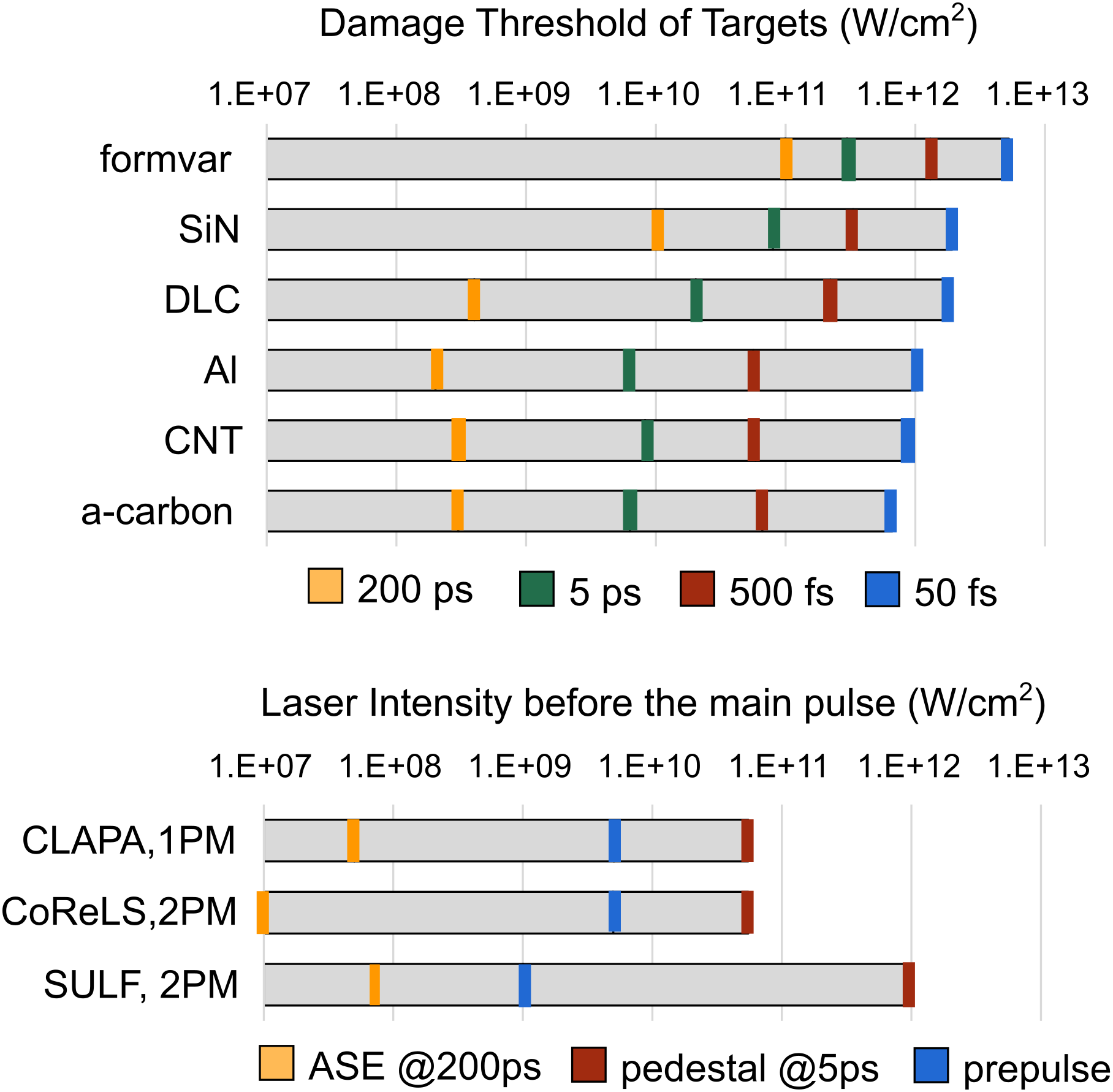
To investigate whether ultrathin targets can be safely used in the experiments performed in the previously described laser facilities, we assume the peak intensity in CoReLS, SULF, and CLAPA is 5×10²¹, 1×10²¹, and 5×10¹⁹ W/cm2, respectively, based on reported results[Reference Wang, Ma, Bin, Alinger, Shou, Wang, Liu, Zhu, Cao, Mei, Wang, Lu, Lin, Zhao, Schreiber and Yan24, Reference Kim, Pae, Choi, Lee, Kim, Singhal, Sung, Lee, Lee, Nickles, Jeong, Kim and Nan45, Reference Chu, Liang, Yu, Xu, Xu, Ma, Lu, Liu, Leng, Li and Xu46]. Figure 5 shows the DTIs of the six kinds of targets as histograms. One can easily see all the targets will be damaged by the fs-prepulses or ps-pedestal. In order to use ultrathin targets, additional contrast improvement techniques need to be applied. The most successful technique up to now, if not the only, is the plasma mirrors (PMs). A PM acts on the compressed pulse as a picosecond gated temporal switch and thus reflects only the ultrashort high-intensity pulse[Reference Vincenti, Monchoce, Kahaly, Bonnaud, Martin and Quere47], usually providing a contrast ratio improvement of the order of 102 (104) for a single (double) PM. When a single PM is applied, 20%–30% laser energy will be lost as the price.

Figure 5 Comparison between DTIs of the tested ultrathin foils and the prepulse intensity.
Figure 5 can be used to evaluate how many PMs need to be applied to avoid prepulse-induced damage and pre-expansion for a specific kind of ultrathin target. For example, by applying 1 PM to CLAPA, 2 PMs to CoReLS, and 2 PMs to SULF, the prepulse intensity will drop by more than 2, 4, and 4 orders, respectively. The corresponding prepulse intensity histograms are drawn below the DTI histograms in Figure 5. For a specific target, if its DTIs at 50 fs/500 fs/200 ps are higher than the fs-prepulse intensity, the ps-pedestal intensity at 5 ps, and the ns-ASE intensity at 200 ps, respectively, such a target would still be intact until 5 ps before the main pulse. One can easily make the judgment by comparing the bars with the same color in the two histograms. The conclusion is that all the ultrathin foils can be safely used in CLAPA with a single PM and the CoReLS with double PMs, but only formvar can be safely used in SULF even with double PMs. For all three lasers, the dominant constraint comes from the ps-pedestal intensity. When the ps-pedestal reaches the intensity of over 1012 W/cm2, shock with speed about 10 nm/ps will be launched first in the targets[Reference Wang, Shou, Wang, Liu, Li, Gong, Hu, Ma and Yan48]. Then the targets will be ionized by the fast-rising pedestal and start to expand. How such an expansion influences the ion acceleration depends on the thickness of the foil, the expansion speed, and the expansion time.
6 Conclusion
In conclusion, we have performed experimental studies on the single-shot optical damage threshold of multi-type ultrathin foils used for laser-driven ion acceleration by using laser pulses with durations from 50 fs to 200 ps. We found the damage thresholds of the free-standing ultrathin foils are significantly lower than those of corresponding bulk materials. Dielectric targets such as formvar and SiN have the highest DTF among all the tested targets. The DTFs of DLC, Al, amorphous carbon, and CNT targets are all below 0.1 J/cm2 with weak dependence on the pulse duration. The obtained damage thresholds are very valuable to help to judge whether a specific target can be safely used in experiments by comparing them with prepulse intensity of lasers in a simple diagram.
Acknowledgments
This work was supported by the National Grand Instrument Project (No. 2019YFF01014402), NSFC innovation group project (No. 11921006), National Natural Science Foundation of China (Nos. 11775010, 11535001, and 61631001), and State Key Laboratory Foundation of Laser Interaction with Matter (No. SKLLIM1806). The authors thank Dr. Jianhui Bin and Mr. Alinger Klaus for their help in the experiments.


 Open access