

Abstract
Light emission from inorganic crystals due to elastic loading, termed piezoluminescence or EML, is of great practical interest due to repeatability of emission. Two architectures demonstrated for utilization of EML are thin films and particulate composites, with the majority of recent literature focusing on the latter. Specifically, EML of doped zinc sulfide phosphor particles dispersed in polymer matrices has been recently demonstrated for a growing number of applications. This necessitates the need to understand the micromechanics of stress transfer within these composites for building accurate EML models as well as fatigue models to predict functional life estimates of the EML devices. Macroscale stress measurements can be combined with material properties through micromechanical models to estimate stress transfer to the particulate phase. Apart from the material properties of the matrix and particles, the bonding between the two phases also influences stress transfer significantly. The bonding at the interface is modeled through a CZM which provides a deterministic way to track interfacial damage due to fatigue. A bilinear CZM defines the undamaged stiffness of the interface ( and its resistance to damage (
 in two piecewise linear stages. In this paper, we utilize established micromechanical models to determine the stiffness of the undamaged interface
  between EML ZnS:Cu particles and PDMS matrix in the normal and tangential directions (
 and
and  ) with the help of experimentally determined mechanical and morphological properties of EML–PDMS composites.
  and
and  determined are then validated by comparing stress strain behavior of a finite element representative volume with experimental monotonic tensile test results to find good correlation.
Export citation and abstract BibTeX RIS
Nomenclature
| CZM | Cohesive zone model |
| DIC | Digital image correlation |
| EML | Elastico-mechanoluminescence |
| PDMS | Polydimethylsiloxane |
| RVE | Representative volume element |

| Opening displacement |

| Nominal opening displacement |

| Critical opening displacement |

| Undamaged stiffness of interface |

| Undamaged stiffness in normal direction |

| Undamaged stiffness in tangential direction |

| Rate of damage accumulation or softening of the interface |

| Volume fraction of the composite |

| Engineering strain |
| E | Young's modulus |

| Poisson's ratio |
| K | Bulk modulus |

| Shear modulus |

| Particle radius |

| Ratio of particle stress to matrix stress |
1. Introduction
Particulate polymer composites consist of organic or inorganic particulate fillers (carbon-black, silica, talc, metal particles, etc) dispersed in a polymeric matrix which behave isotropic at the macroscale. Addition of particulate phase is aimed at improving mechanical, thermal, electrical or other physical properties [1]. Mechanical strength and modulus of the composite are dependent on the matrix and particulate properties. The bonding between the two phases which can significantly affect composite mechanical behavior is generally assumed to be perfect and is ignored from the models. Interfacial bonding strength also affects stress transfer to the particulate phase significantly and demands attention especially if the particulate phase is 'smart' or 'active'.
Smart functionality such as piezoelectricity or magnetostriction can be achieved with smart material fillers as the particulate phase. Smart particulate composites offer considerable material selection flexibility, wider product design space, spatially continuous sensing and multifunctionality capabilities compared to conventional ceramic or single-crystal smart materials [2, 3]. A key drawback of smart composites is the low sensitivity arising from lack of long-range order which is indirectly due to the anisotropic smart behavior [4, 5]. Achieving long-range isotropy necessitates complications in fabrication, for example, poling of piezoelectric particulates simultaneously while curing matrix phase [6]. However, in the case of EML materials, light emission is observed when elastically straining the particles in any direction [7]. EML particulate composites do not require complicated fabrication and have been reported to show strong, repeatable luminescence visible in room-lit conditions. EML particulate composites have been gaining attention for light generation [8], structural health monitoring [9], stress visualization [10], pressure mapping, etc [11].
Operation of EML particulate composite devices involves repetitive mechanical actuation for continuous light generation or sensing. It has been reported that performance of ZnS:Cu EML composites declines over repetitive actuation [8, 9]. ZnS:Mn,Cu shows self-recovery behavior through which EML intensity is recovered with each actuation cycle [12]. Hence, decrease in input stimuli (stress) can be the only cause of performance decline with cycling. It is therefore hypothesized that damage accruing at the interface between the matrix and the EML particles can result in reduced stress transfer and subsequent reduction in emission intensity. Damage at interface also reduces overall stiffness of the composite, allowing for larger strains in the next actuation cycle. Larger strains damage interface further, which leads to reduced overall stiffness, reduced stress transfer and so on.
Modeling the interface damage in EML composites can validate performance decline and help arrive at lifetime estimates for these devices. It can help accurately estimate stress transferred to EML particles from the matrix thereby improving current EML mechanism models or aid in development of new ones. It can aid better matrix selection and identify possible surface treatments to improve stress transfer and subsequent EML emission. Overall, modeling interface damage in EML composites can contribute to improving the sensitivity, reliability and performance for all the developing applications.
Towards this goal, we adopt the CZM approach to describe the particle–matrix interface [13]. CZM defines the interface as a softening spring with a maximum initial stiffness in its undamaged state. The stiffness starts degrading beyond a nominal strain and goes to zero at a critical strain. A typical CZM, called bilinear CZM, is shown in figure 1. The undamaged phase when the interface has a maximum stiffness  is termed Stage-I. The superscript
  refers to the interface. The softening phase when damage starts accruing is called Stage-II. The rate of damage accumulation or rate of softening is defined by
  . The nominal opening displacement,
  , is generally very small compared to the critical opening displacement
  . Hence, the softening stiffness
  is more consequential than the undamaged stiffness
  towards estimating composite damage and health.

Figure 1. Bilinear CZM for EML–PDMS interface with initial stiffness  which degrades to
  due to damage.
Download figure:
Standard image High-resolution imageIn this paper, we focus on estimating the undamaged stiffness  of the EML particle–PDMS matrix interface. Stage-I behavior of the interface may be nonlinear and time dependent since the matrix and the composite show nonlinear time-dependent behavior. However, we assume that it can be described solely based on linear elasticity and predict the stiffness, since Stage-I nonlinearity may not play a critical role in the overall composite's health. We utilize the micromechanical model devised by Tan et al [14] to estimate
  in the direction normal the particle surface. Models by Nazarenko et al [15] and Hashin [16] are then compared to obtain the stiffness in the tangential direction. The models relate the mechanical properties of the individual phases and
  to the macroscopic composite moduli through small-strain linear elastic assumptions. In order to examine how far off the linearly elastic spring assumption is, we conduct simple 2D finite element method simulation and compare the results against experimental data. The comparison shows reasonable agreement despite all the assumptions made.
2. Experimental methods
Composite coupons of EML particles in PDMS elastomer matrix are fabricated as described in our previous work [17]. Dow Corning Sylgard 187 and Osram Sylvania GG45 and GG13 phosphors are used to fabricate the composite coupons. GG45 and GG13 are mixed in equal weight proportions. The weight ratio of EML particles to PDMS matrix is set to 2:1 and that of PDMS base to curing agent is 10:1. The master coupons are 40 mm long, 20 mm wide and 1 mm thick. 2 mm wide specimens are cut out from master coupons for tensile testing.
2.1. Particle size distribution and composite volume ratio estimation
An EML–PDMS composite coupon, made as mentioned above, is flash frozen by immersing in liquid N2 and then fractured into two pieces by bending. Scanning electron micrographs (SEM) of the fracture planes are captured (figure S2(available online at stacks.iop.org/SMS/30/015016/mmedia)). ImageJ software is used to calculate the total pixel area occupied by all particles in a region of interest [18]. The ratio of particle area to the total area of the region is computed as the volume fraction  of the composite. Particle size distribution is estimated from separate SEM images of GG45 and GG13 particles (figure S3). The major and minor diameters (d1, d2) of the particles in view are measured using ImageJ software. The particle diameter is calculated as
 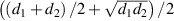 . The resulting size distribution for a mixture of GG45 and GG13 particles in equal parts by weight is shown in figure S4.
2.2. Composite mechanical characterization
Uniaxial tensile test is performed on PDMS elastomer and EML–PDMS composite specimens following ASTM-D412-16 standard for mechanical characterization [19]. Specimen dimensions recommended by the standard are scaled down by a factor of three to fit within the extension limits of current experimental setup. Rectangular specimens measuring 40 mm, 2 mm and 1 mm in length, width and thickness are used for tensile testing. Despite scaling down specimen dimensions, tests were performed at strain-rates close to 0.25 s−1 as specified in the ASTM standard.
Tensile testing is performed on a specially designed setup assembled on an optical microscope stage as shown in figure 2. X-directional rack and pinion drive of the microscope stage (Meiji Techno MA917R) is motorized by a servo motor. One end of the coupon is held by a grip connected to the motorized drive while other end is held by stationary grip connected to a MLP10 load cell from Transducer Techniques in series which measures the axial force. The objective, eye-piece and top–down LED housing of the microscope are removed for the tensile tests as shown in figure 2(a). This is done to accommodate a Windows Lifecam camera, which is placed vertically above the specimen with its plane of view parallel to the plane of loading. Applied strain is measured from videos of the specimens during the tensile test captured by the camera.

Figure 2. (a) Uniaxial tensile test setup on an optical microscope stage. (b) Schematic of setup instrumentation. (c) Camera view of specimen at zero-strain. (d) Camera view of specimen after failure.
Download figure:
Standard image High-resolution imageRed, green and blue (RGB) values-based edge detection is employed to compute longitudinal and lateral strains in every captured frame. The EML–PDMS composite specimens appear white in the grayscale footage, with RGB values above 200. Two markings, parallel to y-axis and along the edges of the grips, are made on the specimen with a fine-tip black Sharpie. The black markings have RGB values below 50 providing high contrast and easy detection against the white specimens. Transparent PDMS specimens required modifications for RGB-based edge detection. Two additional markings along the specimen edges were made and a white background is used to provide high contrast of markings for easy detection.
The average number of pixels within the two markings ( ) along the loading direction are measured in every frame for accurate longitudinal strain measurement. Similarly, the background is painted dark for maximum contrast with the specimen aiding accurate edge definition and width pixel (
 ) computation for lateral strain measurement. Each pixel measures 0.055 mm. The load cell measurements are time-synced with the video to map nominal stress to applied nominal strain. The frame right before application of longitudinal strain is picked as the reference frame.
  and
and  are measured as the length and width from reference frame. Nominal strains at nth frame are computed as
  ,
,  , and the Poisson function is calculated as
  .
.
All composite specimens are strained till failure and all PDMS specimens are strained to large strains (>0.3). Small-strain micromechanics models require elastic modulus (E) and Poisson's ratio  of both composite and PDMS matrix. E and
  are obtained from linear fits within 5% strain limits to the engineering stress–strain curves and the lateral strain to longitudinal strain curves respectively. Towards accurate modeling in finite element analysis (FEA), the non-linear behavior of PDMS is fit with a hyperelastic model using ABAQUS FEA software [20]. Stress relaxation test is also performed on PDMS specimens to obtain its viscoelastic Prony series, which is utilized in FEA to account for rate-dependent behavior. The second part of this paper will take the nonlinear behavior of the composite into consideration towards estimation of CZM damage characteristics. The composite will be modeled as a finite-strain material by utilizing the engineering stress–strain data obtained here.
2.3. Finite element model for validation
A 2D square RVE measuring 150  in length and width with 39 circular particles of varying diameter representing the size distribution is built in ABAQUS FEA software as shown in figure S5. The matrix is shown in blue has 7695 elements and particles in gray have 6463 elements. The number of particles was selected to achieve the volume fraction of the composite
  . A MATLAB code picks the centers of the particles within the RVE at random while satisfying constraints on minimum particle–particle and particle–boundary distances. The constraints avoid meshing difficulties. The first constraint also avoided the need to define particle–particle interaction properties. Top and bottom edges of the RVE were defined with periodic boundary conditions to ensure spatial repeatability.
All particles are defined as linear elastic material with Young's modulus and Poisson ratio of cubic-ZnS from published datasheets [21]. The particle–matrix interfaces are defined as cohesive surfaces with estimated stiffness  and no damage. Uniaxial tensile test data of pure PDMS specimens along with the estimated Poisson's ratio is fed to ABAQUS FEA to estimate the hyperelastic fit. The second order Ogden model was selected as it had minimum fit error and was stable for all strains.
The stress–strain response of PDMS matrix and EML–PMDS composite both show rate-dependency and the elastic modulus depends on the rate of applied strain. Hence, the rate-dependent viscoelastic behavior of the matrix is taken into consideration in the model for accurate representation and comparison of simulation results with experimental data. Towards this, Prony series fit of the PDMS modulus relaxation is utilized to describe matrix's viscoelastic behavior. Further, the RVE is strained at the same rate as the experimental tensile test, by utilizing the time-series data from experiments.
Monotonic strain loading applied in the x-direction as displacement boundary condition on the right edge while the left edge is constrained in the x-direction. Monotonic strain amplitude applied on the RVE is obtained from the uniaxial tensile test experiments. Two variants of the model are implemented, one with plane strain and another with plane stress formulation mesh elements (CPE3/4R and CPS3/4R, respectively), with all other the material properties, constraints and boundary conditions remaining identical. The two formulations are used to compare results from the 2D model with experimental data.
3. Results and discussions
3.1. Mechanical characterization
Tensile testing of pure PDMS and EML–PDMS composite specimens were performed to estimate elastic moduli and Poisson's ratios. Elastic modulus  is computed as the slope of a linear fit to experimental stress–strain curves up to 5% strain limit. Due to limitation on camera framerate, experimental data is captured roughly every 0.8% strain for a tensile loading performed at ASTM standard specified strain-rate. This results in only 5–7 data points within the 5% strain limit per loading curve. Hence, to improve accuracy of computed modulus and Poisson's ratio values, 23 pure PDMS specimens and 10 EML–PDMS composite specimens were tested. Figures 3(a) and (e) show the stress–strain curves for PDMS and EML–PDMS specimens respectively. Figures 3(b) and (f) show the variation of lateral strain to longitudinal strain for PDMS and EML–PDMS specimens respectively.

Figure 3. (a) Engineering stress strain curves (with second order Ogden fit from ABAQUS) and (b) variation of lateral strain with longitudinal strain for 23 pure PDMS specimens. (c) and (d) show same data within 5% strain limits. (e)–(h) show similar experimental data for 10 EML–PDMS composite specimens.
Download figure:
Standard image High-resolution imageSlope of the linear fits within 5% strain gives the elastic modulus  and Poisson's ratio
  of the composite to be 6.93 MPa and 0.348 respectively. Figures 3(c) and (d) give the elastic modulus
  and Poisson's ratio
  of the PDMS matrix to be 1.808 MPa and 0.423, respectively. Figure S1 shows the stress relaxation curves obtained for plain PDMS specimens along with the Prony series fit for modeling modulus relaxation.
3.2. Micromechanical model for interface CZM
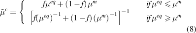
Mori–Tanaka based model detailed by Tan et al [14] is utilized to estimate the undamaged stiffness of the particle–matrix interface in the normal direction. The model links the undamaged stiffness of the interface to the composite bulk modulus considering the mechanical properties of the matrix and particle as well as the volume fraction and size distribution.
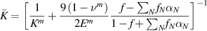
where E is the elastic modulus, K is the bulk modulus,  is the shear modulus,
  is the Poisson's ratio and f is the volume fraction of particles in the composite.
  is the radius and
  is volume fraction of the of Nth size of particles.
 is defined as the ratio of average stress in particle of Nth size to the average stress in matrix.
  is the undamaged stiffness of the particle–matrix interface in the normal direction. Superscripts m and p refer to matrix and particles respectively and the bar accent indicates composite properties.
  and
and  are obtained from figure 3, while
  are obtained from datasheets [21]. Bulk modulus and shear modulus are calculated as
 ![$K = \,E/\left[ {3\left( {1 - 2\nu } \right)} \right]$](https://content.cld.iop.org/journals/0964-1726/30/1/015016/revision3/smsabc6b6ieqn61.gif) and
and ![$\mu = \,E/\left[ {2\left( {1 + \nu } \right)} \right]$](https://content.cld.iop.org/journals/0964-1726/30/1/015016/revision3/smsabc6b6ieqn62.gif) respectively. All the computed parameters are tabulated in table 1. For these parameters, through equation (3), the undamaged interface stiffness in the normal direction
respectively. All the computed parameters are tabulated in table 1. For these parameters, through equation (3), the undamaged interface stiffness in the normal direction  is computed to be 20.55 MPa µm−1. From equation (3),
  and
and  corresponding to
  are 1.1995 and 0.5677, respectively.
Table 1. Material properties used for micromechanical models.
| Parameter | Unit | Composite | Matrix | Particles |
|---|---|---|---|---|
| Young's modulus E | MPa | 6.93 | 1.808 | 98 100 |
| Poisson's Ratio ν | — | 0.348 | 0.423 | 0.4 |
| Bulk modulus K | MPa | 7.5987 | 3.9134 | 163 500 |
Shear modulus 
| MPa | 2.5705 | 0.635 | 35 036 |
| Density ρ | G cc−1 | 2.0073 | 0.97 | 4.0856 |
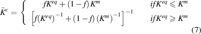
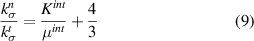
Energy equivalent inhomogeneity model proposed by Nazarenko et al [15] is utilized to obtain the shear or tangential stiffness of the particle–matrix interface ( . Specifically, the spring layer model for the interface of spherical particles is utilized. The bulk and shear moduli of an equivalent inhomogeneity incorporating particle and interfacial spring stiffness are given by the following equations for a zero-thickness interface.

Using method of conditional moments, Nazarenko et al [15] arrive at the following scalar expressions for effective bulk and shear moduli of the composite.
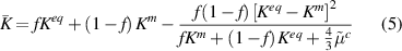
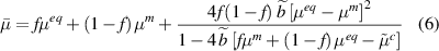
where
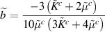
and  are as follows,
Utilizing the parameters in table 1 and interface stiffness in the normal direction  computed from equation (3), we can compute
  that gives
  from equation (6) equal to the experimentally measured shear modulus of the composite. Doing so, we obtain
  to be 88.18 MPa
  m−1. The corresponding composite bulk modulus predicted by equation (5) is 8.13 MPa which when compared to the experimentally measured composite bulk modulus of 7.5987 MPa corresponds to a 7% variation.
It is important to report that the interface stiffness values predicted by these models vary over large ranges as they are extremely sensitive to the Poisson's ratio measurements of the composite and the matrix. Variations in the order of 10−2 in Poisson's ratio can result in 1 order of magnitude variation in interface stiffness values. Hence, considerable number of experimental data sets were utilized to estimate Poisson's ratio of the EML composite and PDMS matrix.
However, an unavoidable consequence of experimental variability in Poisson's ratio measurements is the result that  is about four times larger than
  . Though the interface can be anisotropic, it is unlikely for the tangential stiffness to be higher than normal stiffness. Hashin [16] predicted that the normal stiffness will be substantially larger than the tangential stiffness, at least for the case of a thin interface (non-zero thickness). This result is for a single spherical inclusion in an infinite matrix with imperfect interfacial bonding which is a simpler problem than Nazarenko et al [15] as it does not take into consideration a composite with a distribution of particles with a certain volume fraction. But adopting Hashin's model [16] ensures the EML–PDMS interface is defined by parameters consistent with isotropic behavior. The tangential stiffness
  is derived by Hashin [16] to be a function of
  as follows.
The bulk and shear modulus of the interface are difficult to measure or predict. However, assuming the interface to be isotropic, we can estimate the ratio of the moduli in terms of Poisson's ratio. For isotropic materials, ![$K = \,E/\left[ {3\left( {1 - 2\nu } \right)} \right]$](https://content.cld.iop.org/journals/0964-1726/30/1/015016/revision3/smsabc6b6ieqn79.gif) and
and ![$\mu = \,E/\left[ {2\left( {1 + \nu } \right)} \right]$](https://content.cld.iop.org/journals/0964-1726/30/1/015016/revision3/smsabc6b6ieqn80.gif) . Hence,
. Hence,
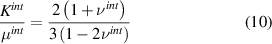
Estimating or measuring the Poisson's ratio of the interface  is also not feasible, but we can assume that it will be similar to the matrix and the particle Poisson's ratios. We therefore assume
 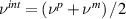 . From table 1,
  . Therefore, from equation (10),
 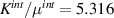 and
and  and for
 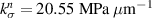 , we get
  . The two stiffness parameters defining the interface CZM (
 are fed into ABAQUS finite element software to define the cohesive behavior of the particle–matrix interface. Damage initiation and stabilization are not defined for the interface.
3.3. Finite element simulations
Monotonic strain loading is applied on the RVE in x-direction. Engineering stress is computed as the sum of reaction forces on the right edge nodes divided by the length of the right edge. Engineering stress strain curves obtained from plane strain and plane stress formulations are plotted along with the experimental tensile test data in figure 4.

Figure 4. Engineering stress–strain curves from monotonic loading of plane-strain and plane-stress FEA models plotted with experimental tensile test data for EML–PDMS composites from figure 3(g).
Download figure:
Standard image High-resolution imageIt can be seen that all the experimental stress strain curves lie within the plane strain and plane stress curves up to 5% engineering strain. Further, it is seen that the plane strain formulation matches the experimental data the best. It is important to note that the interface stiffnesses ( estimated from small strain assumption based theoretical models are able to characterize tensile behavior of the EML composites in the relatively small strain regime. Figure 5 shows the lateral strain variation with longitudinal strain. There is a reasonable correlation between experimental and numerical results here as well. Despite nonlinear behavior of PDMS matrix material, defining the undamaged interface spring by linear elasticity seems to work reasonably well as long as overall strain remains relatively small.

Figure 5. Lateral strain plotted against longitudinal strain from monotonic loading of plane-strain and plane-stress FEA models plotted with experimental tensile test data for EML–PDMS composites from figure 3(h).
Download figure:
Standard image High-resolution image
4. Conclusions
The need for estimating the interfacial properties of mechanoluminescent particulate composites is elaborated in this paper. The interface between EML particles and PDMS elastomer matrix is defined by a bilinear CZM. Bilinear CZM defines the interface as a softening spring with the spring stiffness degrading with damage beyond a nominal loading. In the first step towards obtaining the EML–PDMS interface CZM parameters, small-strain linear elasticity based micromechanical models have been employed to estimate the undamaged stiffness  of the interface in normal and tangential directions. The micromechanical models relate the macroscopic composite bulk and shear moduli to the normal and tangential undamaged interface stiffnesses respectively, through mechanical and morphological properties of the individual phases and the composite. Mori–Tanaka based model developed by Tan et al [14] gives normal undamaged interface stiffness
  to be 20.55 MPa
  m−1. Equivalent energy inhomogeneity model developed by Nazarenko et al [15] gives the tangential undamaged interface stiffness
  to be 88.18 MPa
  m−1 which is unrealistic compared to
  . Hence, Hashin's prediction [16] for a single inclusion with imperfect interface is utilized to compute
  to be 3.09 MPa
  m−1. The stiffness estimates are compared with a numerical simulation of a monotonic loading of a 2D RVE model. Experimental tensile testing data falls within the plane strain and plane stress bounds obtained from the numerical model validating the interface stiffness estimates. In subsequent work, the second stage of the CZM defining damage initiation and accumulation properties of the interface will be experimentally obtained, completing the CZM model for the EML–PDMS interface. This model can then be used to predict functional life of EML composites for light generation and structural sensing applications.
Acknowledgments
The authors (S K and V S) would like to thank NSF IUCRC—Smart Vehicle Concepts Center and Honda R&D Americas Inc. for the financial support. The authors would also like to thank Nano Systems Lab at the Ohio State University for SEM microscopy support.