Rotary Adsorption: Selective Recycling of CO2 in Combined Cycle Gas Turbine Power Plants
 Laura Herraiz
 Erika Palfi1
  Mathieu Lucquiaud
- 1School of Engineering, The University of Edinburgh, Edinburgh, United Kingdom
- 2Institute of Petroleum Engineering, Heriot-Watt University, Edinburgh, United Kingdom
A conceptual design assessment shows that the use of structured adsorbents in a regenerative adsorption wheel is technically feasible for the application of selective exhaust gas recirculation (SEGR) in combined cycle gas turbine (CCGT) power plants. As the adsorber rotates, CO2 is selectively transferred from a flue gas stream to an ambient air stream fed to the gas turbine compressor, increasing the CO2 concentration and reducing the flow rate of the fraction of the flue gases treated in a post-combustion CO2 capture system. It imposes an estimated pressure drop of 0.25 kPa, unlike a pressure drop of 10 kPa reported for selective CO2 membrane systems, preventing a significant derating of the gas turbine. An equilibrium model of a rotary adsorber with commercially available activated carbon evaluates the inventory of the adsorbent and sizes the wheel rotor. Two rotary wheels of 24 m diameter and 2 m length are required per gas turbine—heat recovery steam generator train to achieve an overall CO2 capture level of 90% in a CCGT power plant (ca. 820 MWe) with SEGR “in parallel” to the capture plant. Two to five rotary wheels are required for a configuration with SEGR “in series” to the capture plant. A reduction of 50% in the mass of the adsorbent would be possible with Zeolite 13X instead of activated carbon, yet the hydrophilicity of zeolites are detrimental to the capacity and upstream dehydration of the flue gases is required. A parametric analysis of the equilibrium properties provides guidelines for adsorbent development. It suggests the importance of balancing the affinity for CO2 to allow the regeneration of the adsorbent with air at near ambient pressure and temperature, to minimise the inventory of the adsorbent within practical limits. An adsorbent with a saturation capacity of 8 mol/kg, a heat of adsorption from 24 to 28 kJ/mol CO2 and a pre-exponential factor of the equilibrium constant from 2 × 10⁻⁶ to 9 × 10⁻⁶ kPa−1 would result in an inventory below 200 kg, i.e., approximately the limit for the use of a single rotary wheel system.
Introduction
Combined cycle gas turbine (CCGT) and open cycle gas turbine (OCGT) power plants provide dispatchable electricity, ensure security of supply and maintain affordability on the way to a sustainable low-carbon future. Alongside low-carbon technologies, CCGT power plants will continue to play an important role in a diversified electricity portfolio, yet natural gas-fired power plants still produce on average 350–400 gCO2/kWh, well above the levels required for deep decarbonisation of the electricity generation of 10 gCO2/kWh in the United Kingdom. There is a need to capture CO2 emissions from CCGT power plants to drastically decarbonise the electricity system and meet the net-zero greenhouse gas emissions targets by 2050 (Committee on Climate Change (CCC), 2019; European Commission, 2011; International Energy Agency, 2013).
Post-combustion CO2 capture (PCC) from the flue gas of a CCGT power plant raises particular challenges due to the relatively small CO2 concentration and the large volume of flue gases treated in the capture plant, which result in a large size of the absorber train and auxiliary equipment. In this context, the selective recycling of CO2, referred hereby as Selective Exhaust Gas Recirculation (SEGR), is an effective concept to increase the CO2 concentration and reduce the flow rate of the flue gas fed to the carbon capture plant. SEGR effectively intensifies the capture process to achieve cost reduction in the absorber train (Merkel et al., 2013; Diego et al., 2017; Herraiz et al., 2018). The United Kingdom Energy Technology Institute (ETI) reports that every 10% reduction in the capital cost of the capture plant reduces the electricity cost of CCGT with carbon capture and storage (CCS) by 1.5–2% for base load plants. These benefits become increasingly significant for low load factors operation, a likely outcome in electricity systems with increasing amount of variable renewable generation (ETI, 2016).
This work assess the technical and practical feasibility of rotary adsorption with structured adsorbents for the application of SEGR in CCGT power plants equipped with PCC systems. It constitutes a subsequent step to the evaluation of the performance of a CCGT power plant with SEGR conducted in (Herraiz et al., 2018), toward the development and demonstration of the theoretical proof of concept of SEGR through process simulations. For this purpose, a conceptual design assessment of a rotary adsorber is first conducted to evaluate the performance and to estimate the amount of solid material, the size of the wheel rotor and the number of rotary devices that would be required for two power plant configurations: a CCGT with SEGR in parallel and in series to the capture plant. This set the basis to identify the key operation parameters which are used to conduct a sensitivity analysis with the objective of minimising the solid inventory and the size the rotary wheel and, ultimately, providing guidelines for future adsorbent developers for the applications of SEGR.
Selective Exhaust Gas Recirculation: Background and Configurations
SEGR consists of selectively transferring CO2 from a flue gas stream into an air stream which enters the gas turbine compressor. Since other components in the flue gas, e.g. nitrogen and water vapor, are ideally not recirculated, a smaller amount of excess air is replaced, oxygen is diluted to a lesser extent and a higher CO2 concentration is possible in the flue gas, compared to that with “non-selective” Exhaust Gas Recirculation (EGR). SEGR, operated either in parallel or in series with a PCC system, allows concentrations above 14 %vol while maintaining an oxygen concentration in the combustor of approximately 19 %vol (Merkel et al., 2013; Herraiz et al., 2018), well above the 16 %vol limit reported in a GE F-class gas turbine engine to ensure flame stability and complete combustion (ElKady et al., 2009; Evulet et al., 2009).
The block flow diagrams for a CCGT power plant with SEGR in parallel and SEGR in series are illustrated in Figures 1A,B, respectively. Detailed process flow diagrams are presented in previous work by (Herraiz et al., 2018).
• SEGR in parallel consists of diverting a fraction of the exhaust of the heat recovery steam generator (HRSG) into a system transferring CO2 into the air stream of the gas turbine compressor. The selective CO2 transfer (SCT) system operates “in parallel” to the PCC plant.
• SEGR in series consists of a selective CO2 transfer (SCT) system operated downstream of, and “in series” to, the PCC plant.
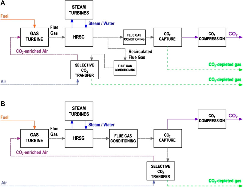
FIGURE 1. Block flow diagrams for a CCGT plant with PCC and with either (A) S-EGR in parallel or (B) S-EGR in series.
A technical assessment conducted by Herraiz et al. (2018) shows that the current class of gas turbine engine can operate with SEGR without a significant deviation in the compressor and the turbine performance from the design-point. By adequately controlling a low compressor inlet temperature, a CO2-enriched combustion air leads to a larger working fluid density and to a higher gas turbine exhaust temperature, which allows additional steam generation. This results in an increase in the net power output and the net thermal efficiency of ca. 43 MW and 0.90 percentage points for a CCGT with SEGR in parallel (820 MWe, 52.84 %LHV), and of ca. 18 MW and 0.53 percentage points for a CCGT with SEGR in series (795 MWe, 52.47 %LHV), compared with an air-based combustion CCGT power plant with PCC (777 MWe, 51.94 %LHV).
Adding SEGR to CCGT power plants would offer operation and cost benefits to any post-combustion CO2 capture process, yet these have to balance the capital and operation cost associated to the system for selective CO2 transfer. Process modeling by (Herraiz et al., 2018) quantitatively estimates reductions of up to 64% in the absorber packing volume and of ca. 7% in the specific reboiler duty for 30 wt% aqueous monoethanolamine scrubbing technology at 90% overall CO2 capture level, for configurations leading to 14 %vol CO2 in the exhaust flue gas.
In practice, the CO2 concentration in the exhaust flue gases would therefore be limited by the highest efficiency that can be achieved with the technologies used for CO2 capture and for selective CO2 transfer. In this paper, post-combustion CO2 capture (PCC) efficiency refers to the amount of CO2 removed from the flue gas in the capture plant relative to the total amount of CO2 in the flue gas entering the plant, as indicated in Eq. 1. Selective CO2 transfer (SCT) efficiency refers to the amount of CO2 removed from the flue gas and transferred into the air stream relative to the total amount of CO2 at the inlet of the CO2 transfer system, as indicated in Eq. 2. The overall CO2 capture level takes into account the amount of CO2 exiting the boundaries of the plant, and it is defined as the amount of CO2 captured for transport and storage/utilization relative to the amount of CO2 generated in the combustion of the natural gas, as indicated in Eq. 3.
The Use of Rotary Adsorption for Selective Exhaust Gas Recirculation
In principle, any technology relying on the CO2 partial pressure difference between a flue gas stream and an ambient air stream as the driving force for selectively transferring CO2 can potentially be used for the application of SEGR. There is therefore an opportunity for existing technologies to be adapted or for new technologies to be developed. Adsorption with CO2 selective porous materials in a rotary configuration is proposed in this article.
Rotary systems constitute a relatively simple configuration to perform cyclic adsorption/desorption processes with a homogeneous temperature distribution since the solid material is simultaneously regenerated and cooled down in contact with ambient air. The adsorption/desorption cycle occurs when the adsorbent rotates and is periodically exposed to the flue gas and the ambient air streams in opposite directions, i.e., counter current flow. CO2 is adsorbed on the solid surface as the adsorption wheel comes into contact with the flue gas, in the adsorption section, and it is desorbed as the adsorbent comes into contact with ambient air, in the regeneration (desorption) section. The contacting mode of the adsorption wheel is analogous to a cross-flow moving bed. A schematic diagram of the system is presented in Figure 2.
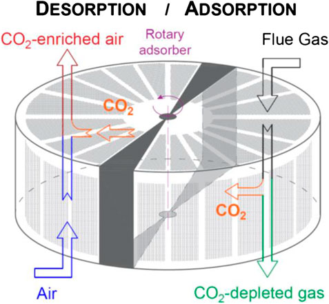
FIGURE 2. Schematic diagram of a rotary adsorbent for selective CO2 transfer.
Moreover the use of structured adsorbents in the wheel rotor, i.e. parallel channel monolithic or laminate structures with controllable shape, cell density and wall thickness, offer practical advantages due to their high void fraction, large geometric surface area and short diffusion length (Brandani et al., 2004; Rezaei et al., 2010). Unlike selective CO2 membranes widely proposed for SEGR applications, structured adsorbents impose little pressure drop on the gas flow and achieve maximum contact areas between the solid and the gas stream enhancing the mass transfer of the components to be removed from the gas stream. A low pressure drop through the CO2 transfer system is critical for SEGR, since a 10 kPa pressure drop expected for membranes results in a 15% derating of gas turbine power output (Herraiz et al., 2018). In contrast, the pressure drop with a structured adsorbent in a wheel is estimated to be 0.25 kPa, derating 0.3% of gas turbine power output. This is further discussed in Conceptual Design Assessment. These values do not include the additional pressure drop through ducts, which would be similar for both technologies.
Applications of Rotary Adsorption
Rotary adsorption is typically employed for air dehumidification systems (Kodama et al., 2001; Ge et al., 2008) and volatile organic compounds (VOCs) abatement systems (Yamauchi et al., 2007), where structured adsorbents are used in the form of adsorbent sheets or monoliths, and the regeneration of the solid material is performed by increasing the temperature.
In the context of CO2 capture from flue gases, adsorption separation processes typically use packed bed (Dantas et al., 2011; Delgado et al., 2011; Serna-Guerrero et al., 2010) or circulating fluidised bed columns (Veneman et al., 2012). Thermal swing adsorption of CO2 in an adsorbent wheel was first investigated by InvenTys (Boulet and Khiavi 2015). Experimental tests and process modeling is conducted within the scope of the “Next Generation CCS Technology” project (NGCT2, 2016), using InvenTys patented Veloxotherm™ technology (Inventys, 2016). A laboratory-scale prototype of a rotary adsorbent was designed and tested under the scope of “Adsorption Materials and Processes for carbon capture from Gas-fired power plants” project (AMPGas 2012), particularly focused on developing advance adsorbents capable to capture CO2 from diluted flue gases and optimising rapid thermal swing regeneration in a rotary adsorber (Gibson et al., 2016). The rotary wheel configuration offers the advantage of a rapid response to thermal swing using a hot stream of steam or air for regeneration (Boulet and Khiavi 2015).
The scale-up of this technology for SEGR applications is likely to be possible from a structural point of view. In large-scale industrial applications, rotary wheel equipment have been dimensioned, implemented and operated in heat transfer applications for large volume of flue gases typically generated in thermal power plants, e.g. regenerative rotary gas/gas heat exchangers (Kitto and Stultz, 1992; Howden Group, 2018).
Adsorbent Selection for Selective CO2 Transfer
For CO2 capture applications, adsorbent materials typically present strong physical or chemical interactions with CO2 molecules and, thus, the regeneration of the solid is conducted by decreasing the pressure, i.e. pressure/vacuum swing adsorption (PSA/VSA), or increasing the temperature, i.e. temperature swing adsorption (TSA) (Mangano et al., 2013; Abanades et al., 2015).
SEGR implies that the regeneration of the adsorbent is conducted with air at near ambient temperature and pressure so that a CO2-enriched air stream is recycled back to the gas turbine compressor. An important aspect is therefore balancing the affinity for CO2 and the energy requirements for regeneration (Ben-Mansour et al., 2016). Physical adsorption appears as an interesting option since a weak interaction requires reduced amount of energy for regeneration, compared to chemisorption that implies new covalent bonds between the sorbate and the sorbent. Although a weak adsorbent-adsorbate interaction is detrimental to the CO2/N2 selectivity (Dantas et al., 2011), the nitrogen partial pressure difference between a flue gas and an air stream is small and a low nitrogen transfer rate would be expected for SEGR applications.
Several types of adsorbent materials have been proposed for CO2 capture from diluted gas streams and extensive review work has been conducted by (Samanta et al., 2012; Hedin et al., 2013; Abanades et al., 2015; Ben-Mansour et al., 2016). Zeolites and activated carbon are initially considered in this work to investigate the concept of selective CO2 transfer, based on their large commercial availability and relatively low cost. A sensitivity analysis of key thermal and physical properties of adsorbent materials conducted in this paper will give insight into promising class of material and will provide guidelines for development of adsorbents for SEGR.
Zeolites present a moderate capacity for CO2 adsorption yet a low selectivity for CO2, which can be increased by the introduction of surface modifications or localised charges. Yet their main drawback is that they are hydrophilic adsorbents and water can displace adsorbed CO2, significantly reducing their actual adsorption capacity in the presence of moisture. Activated carbon however presents a high thermal stability and a low sensitivity to moisture due to the hydrophobic or non-polar nature (Marx et al., 2013; Xu et al., 2013).
Research on stable adsorbent materials under moisture conditions is being conducted along with options to remove the water from the flue gas. For instance, a “water guard” section, made of a suitable material that can be easily regenerated, e.g. alumina or silica gel, can be used in the adsorber column to prevent the water front from moving into the CO2 adsorption section of the hydrophilic adsorbent (Xu et al., 2013). A flue gas dehydration system can also be added (Hasan et al., 2012). It consists of a direct contact cooler followed by either compression and cooling, membrane separation or TEG (triethylene glycol) absorption, and can reduce the water content in the flue gas to 0.1 %vol from saturation conditions downstream of the direct contact cooler, yet further capital and running costs need to be considered.
Current Status of the Technologies Proposed for Selective Exhaust Gas Recirculation
The technology proposed for SEGR in recent work consists of membrane separation systems designed to recover and recycle CO2 from exhaust flue gases using ambient air as a sweep gas. A higher partial pressure gradient across the membrane unit enhances the CO2 transfer separation process, yet the optimal pressure ratio would result from a trade-off between the SCT efficiency and the capital and operational cost of the compression/vacuum equipment that drives system. A higher permeability at the expense of a lower CO2/N2 selectivity is acceptable for SEGR applications and, thus, it is possible to operate at a relatively low pressure difference between the feed stream and the sweep gas, i.e., pressure limited regime (Baker, 2004; Huang et al., 2014), compared to the pressure difference in membrane systems used for CO2 capture. The CO2 separation in the membrane is then driven by the CO2 partial pressure difference between the permeate and the retentate streams, and compression work is mainly required to overcome the pressure drop through the membrane unit, which results in a relatively small power consumption and size of the compression/vacuum system.
The membrane materials investigated for SEGR are CO2 selective polymeric membranes (Baker et al., 2011; Wijmans et al., 2012; Wijmans et al., 2012; Merkel et al., 2013; Diego et al., 2017; Darabkhani et al., 2018; Russo et al., 2018) and solvent supported membranes (Swisher and Bhown 2014; Voleno et al., 2014; Zhang et al., 2016). Merkel and co-workers report a good performance of a specifically developed membrane at laboratory scale, achieving high CO2 transfer efficiencies with a relatively low energy input for flue gas compression to overcome a pressure drop through the membrane system of ca. 100 mbar (Merkel et al., 2013). The effect of the feed pressure on the compressor power consumption has been investigated for a wide range of feed pressures from 25 mbar to 4 bar (Voleno et al., 2014; Diego et al., 2018; Russo et al., 2018). (Diego et al., 2018) reports a loss of ca. 1.3 percentage points in net thermal efficiency of a CCGT power plant for a pressure drop of 105 mbar. The pressure drop through the membranes is therefore a key design parameter which can constitute a limitation for the large scale implementation of membrane technologies.
Experimental work has been conducted in a pilot-scale membrane separation system using a dense polydimethylsiloxane (PDMS) membrane to recover and recycle CO2 from the exhaust stream of a 100 kW natural gas fired burner. Low SCT efficiencies below 10 and 40% are reported for a feed pressure of 1 and 2.4 bar, respectively (Darabkhani et al., 2018; Russo et al., 2018). Moreover, oxygen transfer from the air used as the sweep gas and the presence of water vapor from the combustion might compromise the CO2 separation in real systems. Further investigation is therefore needed to develop new membrane materials to explore the challenges of membrane applications under practical conditions (Diego et al., 2017).
Methodology
The conceptual design assessment of a rotary adsorber for selective CO2 transfer applications conducted in this work consists of two approaches:
• A bottom-up approach considers the best class commercially available adsorbent to conduct a preliminary design of the rotary wheel. This is performed by evaluating the amount of adsorbent, referred here as the inventory of the adsorbent, the dimension of the rotor wheel and the number of wheels that would be necessary to achieve a given CO2 transfer efficiency in each power plant configuration.
• A top-down approach starts with the size of a large rotary wheel to assess the adsorbent performance. A parametric study is conducted, focused on the parameters that have a large effect on the inventory of the solid material such as the parameter of the adsorption equilibrium isotherms and the inlet temperatures of the flue gas and the ambient air, with the objective of minimising the dimensions of the adsorbent wheel. The parametric analysis quantitatively provides the range of physical properties, namely maximum adsorption capacity, equilibrium constant and enthalpy of adsorption, resulting in minimum adsorbent mass requirements and practical rotary wheel dimensions. The ultimate purpose of this second approach is to provide guidelines for new materials development to match the criterion of practicality of rotary wheel systems.
The criterion of practical feasibility for the dimensions of the rotary wheel is based on an analogy with rotary wheel applications for gas/gas heat exchangers. The dimensions of the largest heat exchangers manufactured, implemented and commissioned in the power generation sector are taken as the maximum practical size (Hogg, 2015).
Mathematical Modeling of a Rotary Adsorber for SEGR
At the stage of concept development, the model of the selective CO2 transfer system considers mass transfer and thermodynamic equilibrium. An equilibrium model of the adsorption and desorption processes is developed in gPROMS Model Builder (PSE, 2019).
The system domain is discretized using a finite difference method with
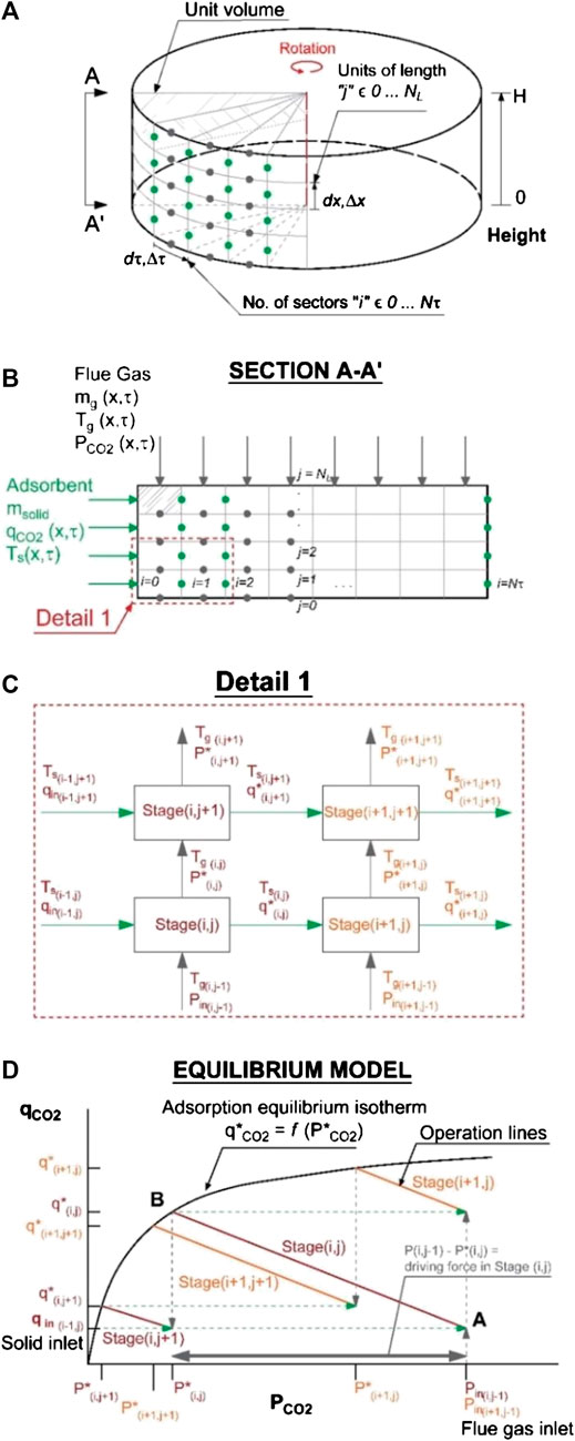
FIGURE 3. Performance model of the rotary adsorber showing (A) the division of the equilibrium model into cells, (B) the cross-flow arrangement, (C) the equilibrium stages, and (D) the operational lines and the equilibrium curve.
The CO2 partial pressure
Energy and Mass Balances
The mathematical model consists of a system of partial differential equations describing the mass and the energy balances in the rotary adsorber (Ruthven, 1984). The mass balance for each component in the gas phase that is adsorbed/desorbed on/from the solid surface is given by Eq. 4, where
The mass balance and the energy balance can be written in terms of the molar flow rate of the component k
A numerical solution discretises the system into equilibrium stages, as indicated in Eq. 8, where an incremental step in the axial direction
Equilibrium Conditions
Mass transfer and thermodynamic equilibrium are assumed in each stage. The gas/air and the solid leave each stage (i,j) at the same temperature as indicated in Eq. 16. The partial pressure of the adsorbate
Boundary Conditions
The inlet conditions are presented in Eqs 18–20. The molar flow rate, composition, temperature and pressure are defined for the flue gas at the top of the wheel
In an adsorption/desorption cycle, the amount of CO2 adsorbed and the solid temperature at the boundaries between the adsorption and the desorption sections, i.e., at
Properties of the Structured Adsorbent and the Rotor Wheel
The equilibrium model evaluates the minimum amount of adsorbent that is required to achieve a certain CO2 transfer efficiency for a given adsorbent material. The volume of the solid
The number of rotary devices
The largest weight of the rotating baskets containing the heating metal elements in the rotary heat exchangers is ca. 1,000 kg. Lager dimensions for the rotary absorber might be possible for SEGR applications due to the considerable smaller density of the adsorbent materials, ca. 1,200 kg/m3, compared to steel, ca. 8,000 kg/m3. Yet a structural analysis would have to be conducted.
The duration of the adsorption/desorption cycles is set by the rotation speed, while the relative residence time of the adsorbent in each adsorption and desorption section is set by the partition of the wheel, i.e. the fraction of the wheel dedicated for each process. A rotation speed of 1 rpm is considered here based on typical values for rotary heat exchangers of similar sizes which are comprised within 0.6 and 1.2 rpm (Hogg, 2015). The optimum rotation speed depends on the capacity and the kinetics. It defines the rate of solid supplied and is equivalent to the solvent flow rate in an amine-based process. One could therefore define an equivalent metric to the liquid/gas ratio of an absorber.
In future work, the selection of the length, the diameter and the rotation speed will be optimised to provide enough residence time and minimize the pressure drop. A rigorous model of the adsorbent wheel will be developed considering mass transfer limitations and diffusion in porous materials.
The power required for the rotation of the wheel is estimated to be of the order of 35 kW and most likely lower, based on a comparison with large scale rotary heat exchangers and internal communication with Howden’s engineers (Hogg, 2015).
Pressure Drop
The pressure drop through the structured adsorbent is calculated using the Hagen-Poiseuille equation shown in Eq. 29 for monolithic and laminated structures (Cybulski and Moulijn, 2005; Rezaei and Webley, 2009).
Adsorbent Selection
The selection of the adsorbent material is based on both general criteria that apply to any CO2 adsorption process from diluted sources and specific criteria for SEGR application. An important aspect of this application is that the regeneration is conducted with ambient air at near-ambient temperature and pressure, unlike in post-combustion CO2 capture applications where a temperature or a pressure swing is required.
The selection of the adsorbent material is based on both general criteria that apply to any CO2 adsorption process from diluted sources and specific criteria for SEGR application. An important aspect of this application is that the regeneration is conducted with ambient air at near-ambient temperature and pressure, unlike in post-combustion CO2 capture applications where a temperature or a pressure swing is required.
The single-site Langmuir isotherm extended to a multicomponent gas mixture (i.e. CO2, N2 and O2) is considered in this model. It is mathematically expressed in Eq. 30, where
The parameters
For each solid, the properties and the parameters of the extended Langmuir isotherm are presented in Table 1. Zeolite 13X presents a higher maximum adsorbed concentration and a higher equilibrium constant for N2 and O2, since it has a higher affinity and selectivity for CO2 compared to activated carbon.

TABLE 1. Properties of the solids and Extended Langmuir equation parameters.
The flue gas and air stream variables for the three configurations of a CCGT power plant with SEGR and PCC, required to conduct the conceptual design assessment of the adsorbent wheel, are presented in Table 2. The selective CO2 transfer efficiency and the post-combustion CO2 capture efficiency are selected in each configuration to achieve 90% overall CO2 capture level, as explained in (Herraiz et al., 2018).
• A CCGT plant with SEGR in parallel operating at 70% recirculation ratio, 97% SCT efficiency and 96% PCC efficiency.
• A CCGT with SEGR in series operating at 95% SCT efficiency and 31% PCC efficiency.
• A CCGT with SEGR in series operating at 90% SCT efficiency and 46% PCC efficiency.
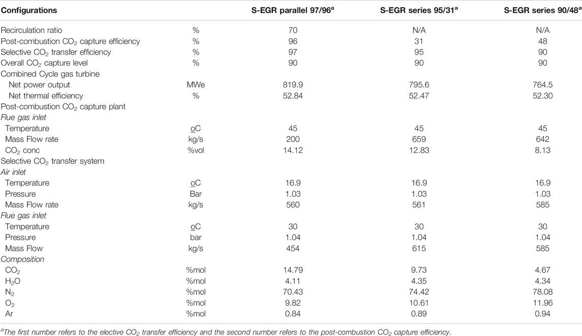
TABLE 2. Operation conditions and flue gas/air inlet streams variables at the selective CO2 transfer system
The CCGT power plant consists of two GE Class F gas turbines (GE9371FB) with the flue gas exiting into two HRSGs, which jointly supply steam to a subcritical triple pressure steam cycle. Two post-combustion capture units with primary amine based solvent technology are implemented at the tail-end, one per each GT-HRSG train.
In the configuration with SEGR in parallel, a fraction of the exhaust flue gas leaving the HRSG is diverted and sent to the rotary adsorber where CO2 is transferred into the ambient air stream entering the GT compressor. The non-diverted gas stream is treated in the PCC plant.
In the configuration with SEGR in series, the exhaust flue gas leaving the HRSG is first treated in the PCC plant where the CO2 is partially removed. The flue gas still contains a relatively high CO2 concentration and is then sent to the rotary adsorber where CO2 is transferred into the ambient air fed to the GT compressor.
Detailed process flow diagrams for both configurations are presented in previous work by (Herraiz et al., 2018). In both configurations, the flue gas entering the selective CO2 transfer system is cooled down to 30°C. It is the lowest temperature achievable in a direct contact cooler (DCC) or a water wash system using cooling water from a recirculating cooling system described in (Herraiz, 2016). A low temperature favors the thermodynamics of the adsorption process and thus enhances the adsorbent equilibrium capacity. It also reduces the water vapor content, since the condensed water drains out of the system, and minimises the sensible heat transfer rate to the air stream, which limits the temperature rise of the CO2-enriched air entering the compressor and prevents derating the gas turbine. The flue gas leaves the DCC saturated and the CO2 concentration and the water vapor content vary with the outlet temperature.
The sweep air stream is ambient air at ISO conditions, i.e. 15°C, 1.013 bar, 60% relative humidity, supplied by an air fan to overcome the pressure drop upstream of the gas turbine inlet. The rise in pressure implies an increase in the air temperature above ambient conditions. An important consideration is that the air flow rate is limited by the maximum volume of air swallowed by the compressor for a fixed geometry, as explained in (Herraiz et al., 2018).
Results and Discussion
Conceptual Design Assessment
To assess the technical and practical feasibility of using a rotary adsorber for SEGR, the following parameters are evaluated: the minimum amount of adsorbent, the volume of the structured adsorbent contained in the rotor and the number and of rotary wheel devices required to achieve a given CO2 transfer efficiency. As indicated in Adsorbent Selection, the dimensions of the largest size rotary heat exchanger commercially available, i.e., 24 m diameter and 2 m length, are considered here to size the adsorbent wheel.
Preliminary dimensions of the wheel are presented in Table 3 for each investigated configuration. For activated carbon, two rotary wheels are required per GT-HRSG train to achieve a SCT efficiency of 97% in a CCGT with SEGR in parallel at 70% recirculation ratio. Two rotary wheels are also required to achieve a SCT efficiency of 90% in a CCGT with SEGR in series, yet five wheels would be required to achieve a SCT efficiency of 95%. This indicates that, for SEGR in series, a significant increase in the inventory of the adsorbent is necessary to gain a marginal increase in the CO2 transfer efficiency due to the lower CO2 concentration (<10 %vol CO2) in the flue gas entering the adsorber wheel compared to that for SEGR in parallel of ca. 15 %vol CO2.
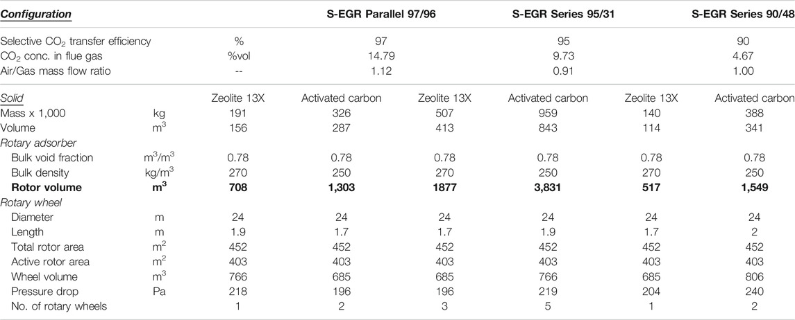
TABLE 3. Adsorbent requirements and preliminary dimensions of the rotary adsorber, per GT-HSRG train.
The amount of activated carbon is twice the amount of Zeolite 13X. Yet the hydrophilicity of zeolites is detrimental to the capacity and upstream dehydration of the flue gas stream would be required to reduce the water concentration from 4 %vol in a saturated flue gases at 30°C to around 0.1 %vol, with the associated increase in the capital and the operational costs.
The pressure drop through the structured adsorbent is ca. 0.25 kPa for a rotor of 2 m length and 200 m2 net flow area. An adsorbent wheel offers a significantly smaller pressure drop compared to a membrane system, with an expected pressure drop of ca. 10 kPa (Merkel et al., 2013; Diego et al., 2017).
Establishing an analogy with large-scale rotary gas/gas heat exchangers, a high pressure drop is estimated by Howden’s proprietary software of ca. 2.5 kPa through the wheel rotor (Herraiz et al., 2015). A smaller rotor diameter for the similar volumes of flue gases is preferred in heat transfer applications, since it results in higher interstitial fluid velocities of ca. 12–15 m/s and favors turbulent flow leading to higher pressure drops. Interstitial fluid velocities of ca. 3–3.5 m/s are estimated for the adsorbent wheels in this work.
In order to gain a better understanding of the performance of a rotary adsorber for the application of selective CO2 transfer, the CO2 partial pressure and the temperature profiles in the gas phase, i.e. flue gas and air streams, and the profiles of the CO2 adsorbed on the solid surface and the solid temperature are presented here for the configuration of a CCGT power plant with SEGR in parallel. Figure 4A illustrates the vertical sections considered to represent the profiles in the flue gas and the air streams, and Figure 4B illustrates the horizontal sections representing the profiles for a unit of volume of adsorbent contained in the rotor of the wheel.
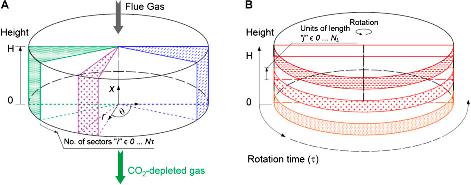
FIGURE 4. (A) Vertical sections, and (B) horizontal sections in the adsorbent wheel.
Profiles of CO2 Partial Pressure and Temperature in the Gas Phase
The CO2 partial pressure and the temperature profiles in the flue gas and in the air as a function of the height of the adsorbent rotor are presented in Figures 5 and 6 respectively, for different vertical sections.
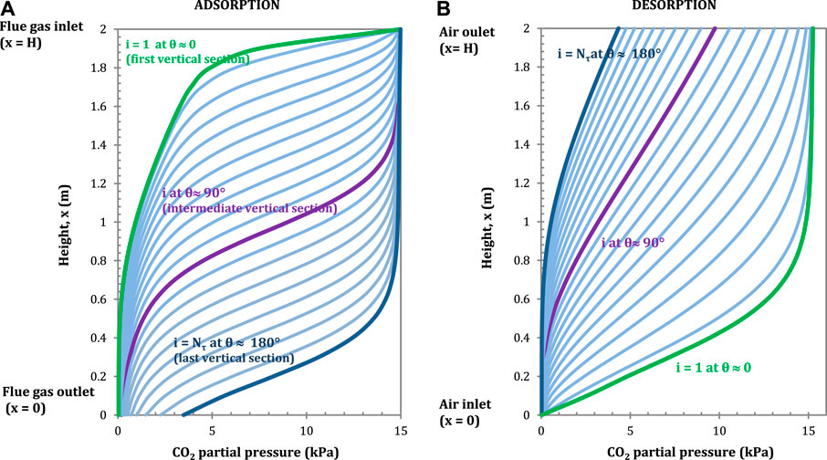
FIGURE 5. CO2 partial pressure profiles in the flue gas (A) (adsorption) and in the air, (B) (desorption) in longitudinal direction for each vertical section. Configuration: S-EGR in parallel at 70% recirculation ratio. Adsorbent: Activated Carbon.
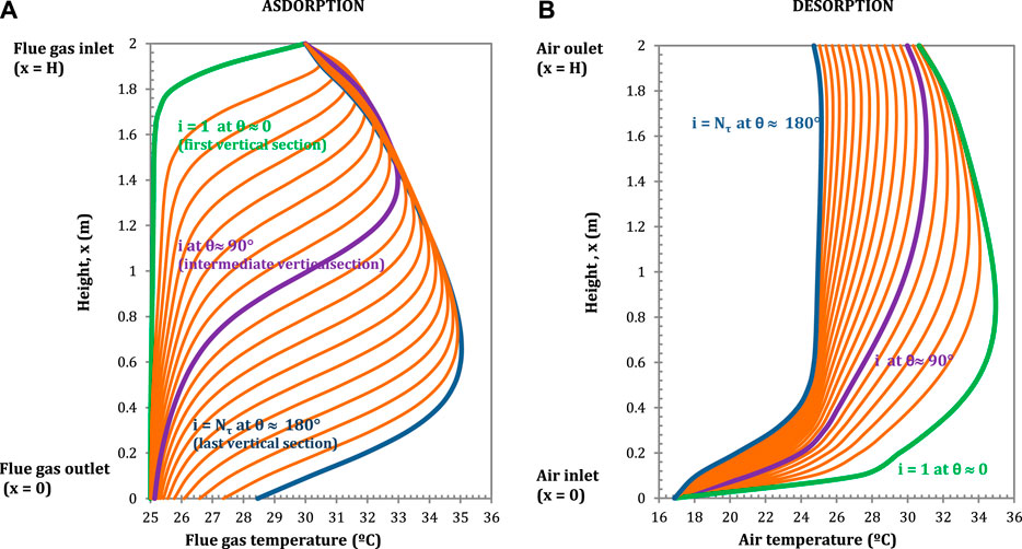
FIGURE 6. Temperature profiles in the flue gas (A) (adsorption) and in the air, (B) (desorption) in longitudinal direction for each vertical section. Configuration: S-EGR in parallel at 70% recirculation ratio. Adsorbent: Activated Carbon.
The highest CO2 adsorption rates correspond to the largest CO2 partial pressure gradients, i.e. the ratio of the marginal change of partial pressure of CO2 for a given change of adsorbent height
The largest partial pressure gradients correspond – counter intuitively – to nearly horizontal sections of the lines in Figure 5A. For example, there is a steep partial pressure gradient when the flue gas enters at the top of the rotor and the partial pressure is reduced from 15 kPa to nearly 4 kPa in a length of 0.2 m, as the flue gas flows from top to bottom.
Similarly, the CO2 partial pressure in the air increases rapidly when the air comes into contact with the solid containing a large amount of CO2 adsorbed in the first vertical section, as indicated by the green line (i = 1) in Figure 5A. The CO2 partial pressure gradient becomes less steep and gradually occurs closer to the air outlet, i.e. top end of the rotor, as the adsorbent rotates, as indicated by the blue line (i = Nτ) in Figure 5A.
The flue gas temperature profiles show a temperature drop when the gas comes into contact with the regenerated adsorbent, since the solid has been cooled down by the ambient air in the regeneration section. A temperature bulge occurs at the locations where the CO2 adsorption rates reach maximum due to the released heat of adsorption, as shown in Figure 6A. Similarly, the air temperature initially increases rapidly, as result of the sensible heat transfer from the solid to the air, and then moderately, due to the endothermic effect of CO2 desorption, as shown in Figure 6B. In the rotary adsorber, the solid acts as a heat storage medium transferring sensible heat from the flue gas into the air stream and, the overall effect is an increase in the air outlet temperature compared to the ambient air temperature. The implications on the power plant performance of the higher temperature of the CO2-enriched air entering the gas turbine compressor are discussed in (Herraiz et al., 2018).
Profiles of CO2 Adsorbed and Solid Temperature
The CO2 adsorbed and the solid temperature profiles in the angular direction are presented in Figures 7 and 8, respectively, for different horizontal sections. The total residence time is the period of an adsorption/desorption cycle and it is inversely proportional to the rotation speed. A rotation speed of 1 rpm is considered here, as explained in Adsorbent Selection.
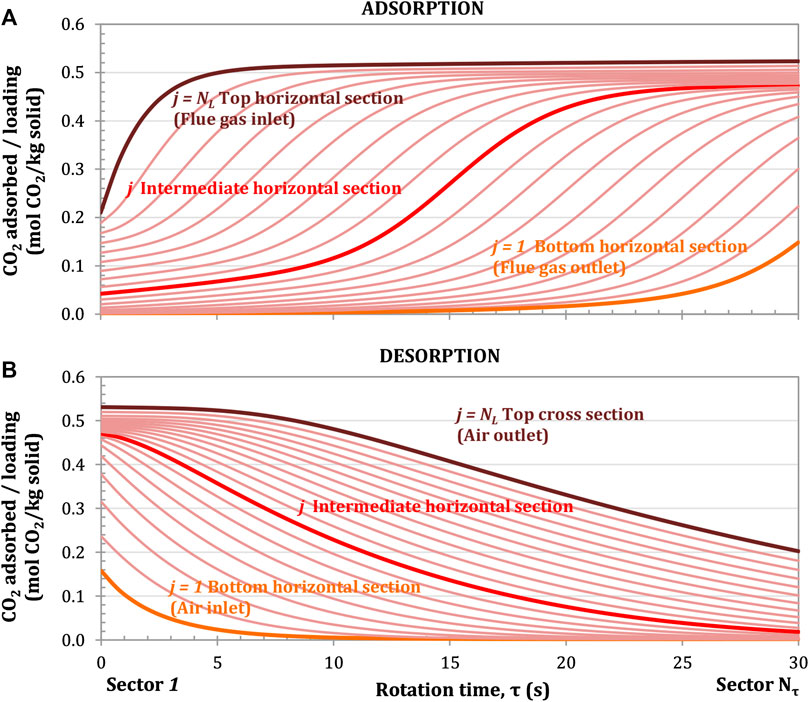
FIGURE 7. CO2 adsorption profile for the adsorption (A) and desorption (B) processes at different horizontal sections. Rotation speed of 1 rpm. Configuration: parallel S-EGR at 70% recirculation ratio. Adsorbent: Activated Carbon.
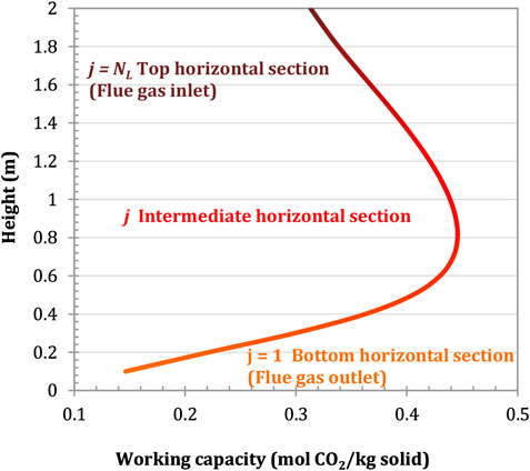
FIGURE 8. Solid temperature profile for the adsorption (A) and desorption (B) processes at different horizontal sections. Rotation speed of 1 rpm. Configuration: parallel S-EGR at 70% recirculation ratio. Adsorbent: Activated Carbon.
The amount of CO2 adsorbed on the solid surface increases as the adsorbent contained in a given unit of volume rotates and is exposed to a portion of the flue gas with an increasingly high CO2 partial pressure. The closest unit volume of adsorbent to the flue gas inlet, i.e. top cross section (j = NL), is fully loaded after 3–4 s due to the largest driving force for CO2 mass transfer, as indicated by the brown line in Figure 7A. The closest unit volume of adsorbent to the flue gas outlet, i.e. bottom cross section (j = 1), is partially loaded at the end of the 30 s adsorption period, as indicated by the orange line in Figure 7A.
For the top cross section closer to the flue gas inlet, the CO2 adsorption rate, i.e. the ratio of a marginal change of adsorbed CO2 for a given incremental step in the angular direction
Figure 7B shows that the adsorbent is not fully regenerated at the end of the cycle, e.g. 60 s for 1 rpm rotational speed, and enters again the adsorption section partially loaded. There is therefore a residual amount of adsorbed CO2 which enters the adsorption section. For instance, the top cross section leaves the desorption section with a loading of 0.2 mol/kg on the right hand side of Figure 7A. The vertically integrated adsorbent loading at the outlet of the desorption section corresponds to 14% of the maximum vertically integrated adsorbent loading achieved at the outlet of the adsorption section. It has to be noted that the model of the rotary adsorber operate at steady-state conditions and there is no accumulation of CO2 on the solid over the cycles, maintaining therefore the same adsorption capacity in each cycle.
The working capacity of the adsorbent is defined here as the difference between the amount of CO2 adsorbed on the solid surface at the beginning (
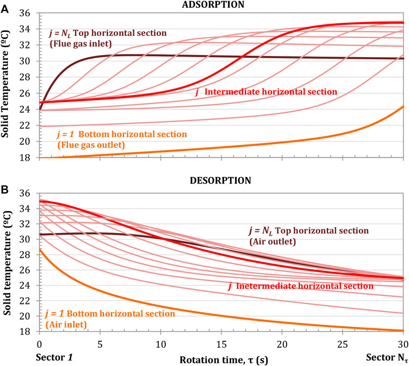
FIGURE 9. Cumulative working capacity of the adsorbent in the longitudinal direction. Configuration: parallel S-EGR at 70% recirculation ratio. Adsorbent: Activated Carbon.
The adsorbent temperature profiles during the adsorption/desorption cycle are illustrated in Figure 8. In the adsorption section, the adsorbent temperature increases due to the heat of adsorption released as the CO2 is adsorbed and the sensible heat transfer from the flue gas to the solid. The larger temperature gradients correspond to the locations where the CO2 adsorption rates are higher and the highest absolute temperatures are reached at the intermediate horizontal sections where the cumulative working capacity is the highest, as shown in Figure 8A. In the regeneration section, the solid temperature decreases due to the endothermic CO2 desorption process and the sensible heat transfer from the solid to the air, as shown in Figure 8B. This constitutes an advantage compared to fixed beds, where a rapid increase in temperature occurs in the adsorption front, decreasing the adsorption capacity.
Parametric Analysis of Solid Properties and Operating Conditions
The objective of the top-down approach is to identify classes of adsorbents optimal for the application of SEGR. The size of the largest commercially available rotary gas/gas heat exchanger is considered here to assess the solid performance. A parametric analysis is first conducted to quantitatively identify the optimal range of values for the parameters of the Langmuir adsorption model, i.e. the maximum adsorbed concentration, the pre-exponential factor of the equilibrium constant and the enthalpy of adsorption, which minimises the inventory of the adsorbent. It is assumed that the maximum adsorbed concentration (physical property) and the adsorption equilibrium (thermodynamic property) vary independently since the homogeneity of the surface and the probability of adsorption of the adsorbed molecules on the solid are independent of the surface coverage.
A sensitivity analysis of the amount of solid to the flue gas temperature and to the air temperature is also conducted here. The objective is to investigate the effect of a higher flue gas temperature downstream of the cooling system and the possible trade-offs of carrying out the adsorbent regeneration at a higher temperature. Carrying out the regeneration at a higher temperature would increase the working capacity, yet feeding a hotter air stream to the gas turbine compressor would result in derating of the gas turbine. This is possible to investigate using the integrated model developed in this work.
Results presented here correspond to a rotary adsorber with activated carbon for the configuration of a CCGT power plant with SEGR in parallel operating at 70% recirculation ratio.
Parametric Analysis to the Solid Properties
Maximum Adsorbed Concentration
In physical adsorption described by the Langmuir model, an increase in the maximum adsorbent concentration,
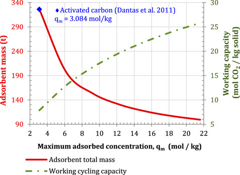
FIGURE 10. Sensitivity of adsorbent mass and working capacity to the maximum adsorbed. Configuration parallel S-EGR at 70% recirculation ratio, 97% selective CO2 transfer efficiency and 96% post-combustion CO2 capture efficiency.
Equilibrium constant and enthalpy of adsorption
The parametric analysis of the adsorbent mass to the pre-exponential factor of the equilibrium constant,
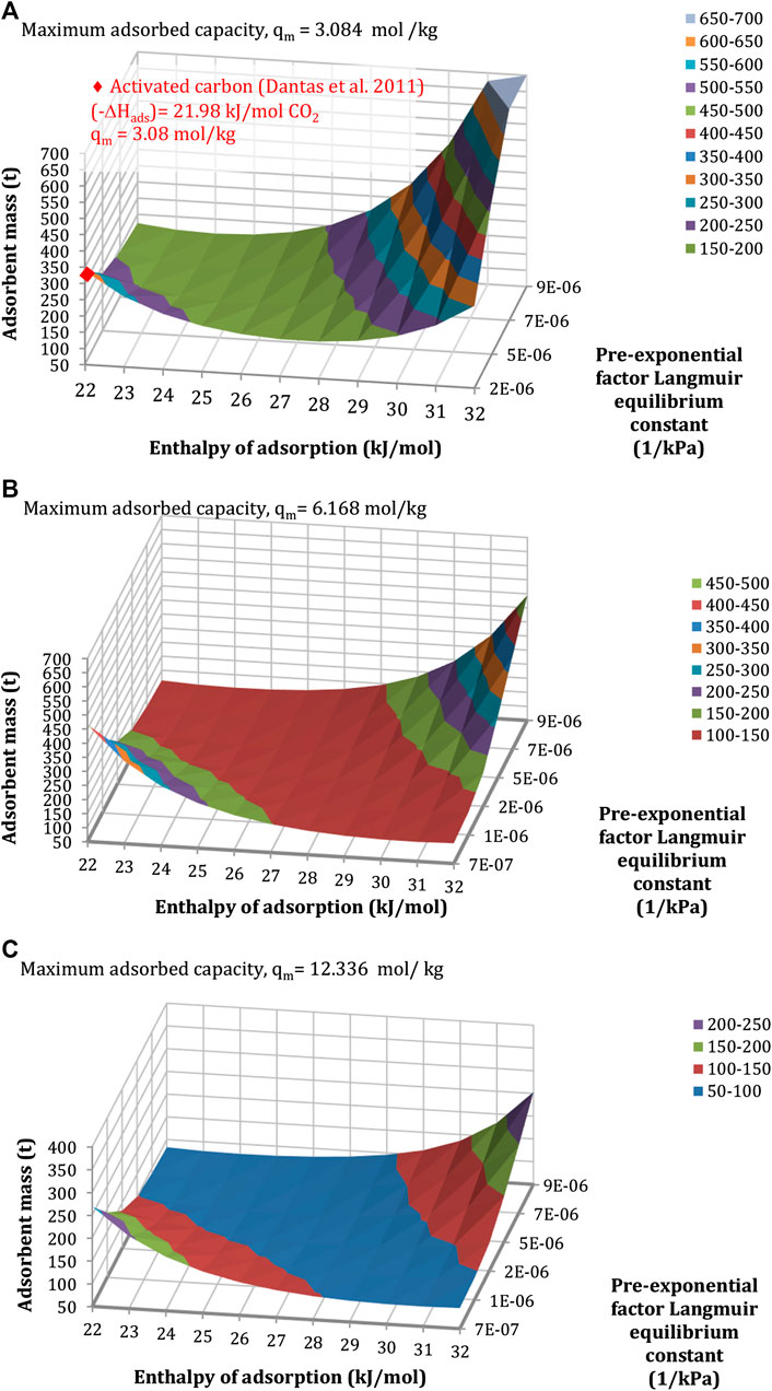
FIGURE 11. Sensitivity of the mass of the adsorbent to the enthalpy of adsorption and the pre-exponential factor of the equilibrium constant, for a maximum adsorbed capacity of (A) 3.08 mol/kg, (B) 6.17 mol/kg, and (C) 12.34 mol/kg. Configuration: S-EGR in parallel at 70% recirculation ratio, 97% selective CO2 transfer efficiency.
Results indicate that for a given maximum adsorbent concentration, there is a combination of values of the enthalpy of adsorption and the pre-exponential factor of the equilibrium constant which minimises the amount of adsorbent. A large value of the equilibrium constant, due to either a large pre-exponential factor or a large enthalpy of adsorption, indicates a strong affinity of the adsorbent for the CO2 molecules, which favours the CO2 adsorption, yet is detrimental for the CO2 desorption. It results in a reduction of the working capacity and an increase in the amount of solid required to achieve a given CO2 transfer efficiency. On the other side, a small equilibrium constant is detrimental for the CO2 adsorption, increasing the amount of solid required.
A solid inventory of approximately 200 kg would require only one rotary device, for the structural parameters indicated in Properties of the Structured Adsorbent and the Rotor Wheel. This corresponds to the pair of values within the blue, red, and purple regions in Figure 11. For instance, for a maximum adsorbed concentration of 3 mol/kg, an enthalpy of adsorption in the range of 24 and 28 kJ/mol and pre-exponential factors from 2·× 10-6 to 9·× 10-6 kPa−1 result in a solid material inventory below 200 kg. The heat of adsorption typically varies between 17 and 22 kJ/mol for activated carbon, and between 30 and 45 kJ/mol for zeolites and metal-organic-frameworks (Abanades et al., 2015; Mangano et al., 2013).
Parametric Analysis to the Operating Conditions
Air Inlet Temperature
The effect of increasing the temperature of the air used to regenerate the adsorbent on the inventory of the adsorbent is shown in Figure 12. This is possible, for instance, by using the available sensible heat in the flue gas leaving the HRSG in a rotary wheel gas/gas heat exchanger to increase the ambient air temperature. Figure 12A shows that a 10°C increase in the air temperature results in an increase in the amount of solid of approximately 5.5 tonnes. A pre-heated air does not favor the CO2 transfer process because the cooling capacity of the air decreases. Despite the fact that a higher temperature favors the CO2 desorption and the regeneration of the solid, the adsorbent enters the adsorption section at a higher temperature than that in the case with air at ambient conditions, as shown in Figure 12B, which is detrimental for the adsorption process. Moreover, the CO2-enriched air outlet temperature marginally increases by 2°C for the range of investigated air temperatures, from 17°C to 57°C, derating the gas turbine in approximately 2 MW, as explained in (Herraiz et al., 2018).
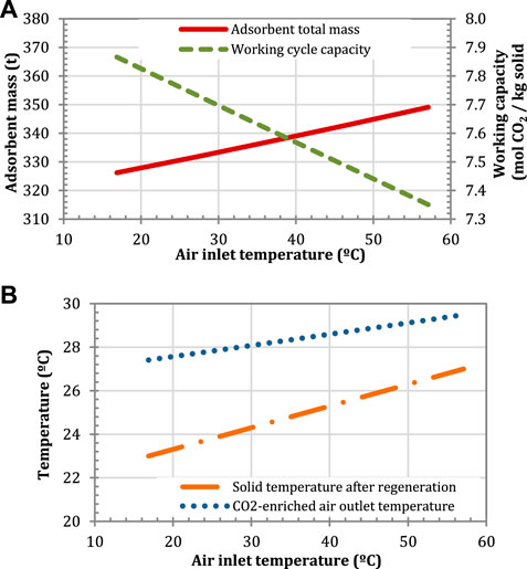
FIGURE 12. Effect of the air inlet temperature on (A) the adsorbent mass and the working capacity, and (B) on the CO2-enriched air and the solid temperatures. Configuration: S-EGR in parallel at 70% recirculation ratio.
The effect of a higher air temperature on the selective CO2 transfer efficiency is also investigated for a given amount of solid. As shown in Figure 13, an increase of 10°C results in a reduction of the selective CO2 transfer efficiency of 0.5 percentage points, which suggests that the efficiency of the process is insensitive to variations in ambient air conditions. The small effect of the ambient air temperature might however be due to the rapid heat transfer in the thermal equilibrium approach. Resistance to heat transfer will be investigated in future work.
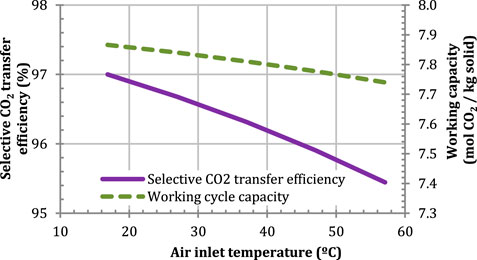
FIGURE 13. Effect of the air inlet temperature on the selective CO2 transfer for a given solid mass of 326.21 t. Configuration: parallel S-EGR at 70% recirculation ratio.
Flue Gas Inlet Temperature
A low flue gas inlet temperature thermodynamically enhances the CO2 adsorption. Although the effect on the amount of solid is marginal, a low temperature is required to minimise the heat transferred into the air stream, so that the temperature of the CO2-enriched air at the inlet of the gas turbine compressor is maintained as low as possible (Herraiz et al., 2018). The lowest possible temperature is however limited by the cooling system and the source of cooling water. The sensitivity analysis is illustrated in Figure 14.
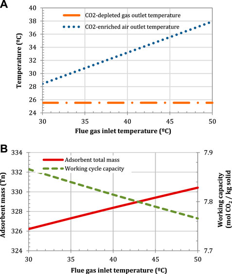
FIGURE 14. Effect of the flue gas inlet temperature on (A) the air and flue gas outlet temperatures, and (B) the adsorbent mass and the working capacity. Configuration: parallel S-EGR at 70% recirculation ratio.
Conclusion
This article investigates the concept of adsorption in a regenerative rotary wheel for the application of selective exhaust gas recirculation (SEGR) as a low-pressure alternative to CO2 selective membrane systems. A rotary adsorber of approximately 24 m diameter and 2 m length imposes an estimated pressure drop of 0.25 kPa, unlike a pressure drop of 10 kPa reported for selective CO2 membrane systems, preventing a significant derating of the gas turbine compressor.
At the stage of concept development, the equilibrium model of a rotary adsorber evaluates the minimum amount of solid and the preliminary dimensions of the wheel rotor, given the adsorption isotherms of CO2 and other gaseous components on commercially available adsorbents. It also estimates the thermo-physical properties for an ideal adsorbent that minimises the inventory of the solid material.
The conceptual design assessment shows that the use of structured adsorbents in a rotary wheel is technically feasible for selectively transferring CO2 from a flue gas stream into an air stream fed to the gas turbine compressor. Yet the development of new materials is necessary to minimise the mass of solid and, eventually, the size and number of rotary wheels within practical limits.
In a bottom-up approach, two commercially available adsorbent materials, activated carbon and Zeolite 13X, are considered to size the wheel rotor. At least two rotary wheels of approximately 24 m diameter and 2 m length, containing 330 t of a commercial activated carbon, are required per GT-HRSG train to achieve a 97% selective CO2 transfer efficiency for a CCGT power plant (ca. 820 MWe) with SEGR in parallel to the carbon capture system. Two rotary wheels, containing 380 t of activated carbon are also required per GT-HRSG train to achieve 90% selective CO2 transfer efficiency for a CCGT power plant (ca. 760 MWe) with SEGR in series to the carbon capture system. Both configurations operate at 90% overall CO2 capture level. For SEGR in series, the relatively small CO2 concentration in the flue gas entering the selective CO2 transfer system, compared to that for SEGR in parallel, results in a significant increase in the amount of solid for a small increase in CO2 transfer efficiency, i.e. 2.5 times more solid is required to gain 5% points in efficiency. A reduction of 50% in the mass of the adsorbent is possible with Zeolite 13X, yet the hydrophilicity is detrimental to the capacity and upstream dehydration is required, with the associated increase in the capital and operational costs. It is necessary that the presence of moisture in the flue gas does not affect the CO2 adsorption capacity of the adsorbent for a range of water concentration in the flue gas up to 10 %vol.
In a top-down approach, key parameters with a large effect on the inventory of the adsorbent, i.e. the parameters of the adsorption equilibrium isotherms and the flue gas and air inlet temperatures, are considered to conduct an optimization study aiming to minimise the dimensions of the SEGR system and provide guidelines for future adsorbents development. Increasing the maximum adsorbed concentration from 3 mol/kg, typically the capacity of activated carbon, to approximately 8 mol/kg significantly reduces the solid mass requirements. Any further increase then results in a marginal gain. A moderate affinity of the adsorbent for CO2 is also preferable to maximise the working capacity and minimise the inventory of the solid material. A heat of adsorption within a range from 24 to 28 kJ/mol CO2 and a pre-exponential factor of the equilibrium constant within a range from 2 × 10⁻⁶ to 9 × 10⁻⁶ kPa−1 would result in an adsorbent mass below 200 kg, i.e., approximately the limit for the use of only one rotary wheel. In comparison, the activated carbon considered as reference in this article has an enthalpy of adsorption of 22 kJ/molCO2 and pre-exponential factor of 2 × 10⁻⁶ kPa−1.
In future work, a rigorous model of the rotary adsorber, including adsorption kinetics, will be used to further investigate this concept and to optimise design and operation parameters, i.e., diameter and length of the rotor, rotation speed, cross section for adsorption and desorption.
Data Availability Statement
The datasets generated for this study are available on request to the corresponding author.
Author Contributions
LH and ML conceived the present idea. LH developed the model and performed the simulations and wrote the manuscript with support from EP, ESF, and ML. EP contributed to the final manuscript. ESF contributed to the development of the model, to the analysis and to the discussion of the results. ML contributed to the discussion of the results and supervised the project and the findings of this work. All authors provided critical feedback and helped shape the research, analysis and manuscript.
Funding
LH and EP are financially supported by the TECRON PhD project (DP/J50040/1), an ESPRC CASE Award funded by the School of Engineering at the University of Edinburgh and Howden Group (Glasgow, Scotland), and the TECC-GAS PhD project, an industrial doctorate funded by the Energy Technology Partnership and Howden Group (Glasgow, Scotland). ML is financially supported by a UK Royal Academy of Engineering Research Fellowship. The authors also gratefully acknowledge the support from the GAS-FACTS project (EP/J020788/1) and the SELECT project (EP/M001482/1), both funded by the UK Engineering and Physical Science Research Council (EPSRC).
Conflict of Interest
The authors declare that the research was conducted in the absence of any commercial or financial relationships that could be construed as a potential conflict of interest.
Supplementary Material
The Supplementary Material for this article can be found online at: https://www.frontiersin.org/articles/10.3389/fenrg.2020.482708/full#supplementary-material.
Nomenclature
Acronyms
ARD Average relative deviation
CCS Carbon capture and storage
DLN Dry low emissions
EGR Exhaust gas recirculation or “non-selective” exhaust gas recirculation
GT Gas turbine
GTCC Gas turbine combined cycle
HRSG Heat recovery steam generator
NGCC Natural gas combined cycle
PCC Post-combustion carbon capture
SEGR Selective exhaust gas recirculation
SCT Selective CO2 transfer
Symbols
Greek symbols
Subscripts
b bed or bulk
g Gas
i Stage in angular direction
in Inlet
j Stage in longitudinal/axial direction
k Component in the gas phase
out Outlet
p Particle
s Solid
Superscripts
* Equilibrium
References
Abanades, J. C., Arias, B., Lyngfelt, A., Mattisson, T., Wiley, D. E., Li, H., et al. (2015). Emerging CO2 capture systems. Int. J. Greenh. Gas Control 40, 126–166. doi:10.1016/j.ijggc.2015.04.018
AMPGas, . (2012). Adsorption Materials and Processes for carbon capture from Gas-fired power plants [WWW Document]. URL http://gow.epsrc.ac.uk/NGBOViewGranNext Generation CCS Technologyt.aspx?GrantRef=EP/J02077X/1 (accessed 2 2 16).
Bai, R.,, and Yang, R. T. (2001). A thermodynamically consistent Langmuir model for mixed gas adsorption. J. Colloid Interface Sci. 239, 296–302. doi:10.1006/jcis.2001.7563
Baker, R. W. (2004). Membrane technology and applications, 2nd Editio. ed, membrane technology and applications. Hoboken: John Wiley & Sons. doi:10.1016/S0376-7388(00)83139-7
Baker, R. W., Wijmans, J. G., Merkel, T. C., Haiqing, L., Daniels, R., and Thompson, S. (2011). Gas separation process using membranes with permeate sweep to remove CO2 from combustion gases. US Pat. 7964020B2.
Ben-Mansour, R., Habib, M. A., Bamidele, O. E., Basha, M., Qasem, N. A. A., Peedikakkal, A., et al. (2016). Carbon capture by physical adsorption: materials, experimental investigations and numerical modeling and simulations – a review. Appl. Energy 161, 225–255. doi:10.1016/j.apenergy.2015.10.011
Boulet, A.,, and Khiavi, S. (2015). Method of adsorptive gas separation using thermally conductive contactor structure/US 2015/0068397 A1. US 2015/0068397 A1.
Brandani, F., Rouse, a., Brandani, S., and Ruthven, D. M. (2004). Adsorption kinetics and dynamic behavior of a carbon monolith. Adsorption 10, 99–109. doi:10.1023/B:ADSO.0000039866.37214.6a
Cybulski, A.,, and Moulijn, J. A. (2005). Structured catalysts and reactors: Second edition, structured catalysts and reactors. doi:10.1201/9781420028003
Dantas, T. L. P., Luna, F. M. T., Silva, I. J., Torres, A. E. B., de Azevedo, D. C. S., Rodrigues, A. E., et al. (2011a). Modeling of the fixed - bed adsorption of carbon dioxide and a carbon dioxide - nitrogen mixture on zeolite 13X. Braz. J. Chem. Eng. 28, 533–544. doi:10.1590/S0104-66322011000300018
Dantas, Tirzhá. L. P., Luna, F. M. T., Silva, I. J., de Azevedo, D. C. S., Grande, C. A., Rodrigues, A. E., et al. (2011b). Carbon dioxide-nitrogen separation through adsorption on activated carbon in a fixed bed. Chem. Eng. J. 169, 11–19. doi:10.1016/j.cej.2010.08.026
Darabkhani, H. G., Jurado, N., Prpich, G., Oakey, J. E., Wagland, S. T., and Anthony, E. J. (2018). Design, process simulation and construction of a 100 kW pilot-scale CO2 membrane rig: improving in situ CO2 capture using selective exhaust gas recirculation (S-EGR). J. Nat. Gas Sci. Eng. 50, 128–138. doi:10.1016/j.jngse.2017.09.012
Delgado, J. A., Uguina, M. A., Sotelo, J. L., Águeda, V. I., Sanz, A., and Gómez, P. (2011). Numerical analysis of CO2 concentration and recovery from flue gas by a novel vacuum swing adsorption cycle. Comput. Chem. Eng. 35, 1010–1019. doi:10.1016/j.compchemeng.2010.07.026
Diego, M. E., Bellas, J. M., and Pourkashanian, M. (2018). Techno-economic analysis of a hybrid CO2 capture system for natural gas combined cycles with selective exhaust gas recirculation. Appl. Energy 215, 778–791. doi:10.1016/j.apenergy.2018.02.066
Diego, M. E., Bellas, J., and Pourkashanian, M. (2017). Process analysis of selective exhaust gas recirculation for CO2 capture in natural gas combined cycle power plants using amines. Proc. ASME Turbo Expo. 2017, June 26-30, 2017, Charlotte, NC, USA GT2017-643, 1–11.
ElKady, A. M., Evulet, A., Brand, A., Ursin, T. P., and Lynghjem, A. (2009). Application of exhaust gas recirculation in a DLN F-class combustion system for postcombustion carbon capture. J. Eng. Gas Turbines Power 131, 034505. doi:10.1115/1.2982158
ETI (Energy Technologies Institute). (2016). Reducing the cost of CCS developments in capture plant technology.
European Commission. (2011). A Roadmap for moving to a competitive low carbon economy in 2050. doi:10.1017/S001447970700590X
Evulet, A. T., ELKady, A. M., Branda, A. R., and Chinn, D. (2009). On the performance and operability of GE’s dry low NOx combustors utilizing exhaust gas recirculation for PostCombustion carbon capture. Energy Procedia 1, 3809–3816. doi:10.1016/j.egypro.2009.02.182
Ge, T. S., Li, Y., Wang, R. Z., and Dai, Y. J. 2008). A review of the mathematical models for predicting rotary desiccant wheel. Renew. Sustain. Energy Rev. 12, 1485–1528. doi:10.1016/j.rser.2007.01.012
Gibson, J. A. A., Mangano, E., Shiko, E., Greenaway, A. G., Gromov, A. V., Lozinska, M. M., et al. (2016). Adsorption materials and processes for carbon capture from gas- fired power Plants : AMPGas. doi:10.1021/acs.iecr.5b05015
Hasan, M. M. F., Baliban, R. C., Elia, J. A., and Floudas, C. A. (2012). Modeling, simulation, and optimization of postcombustion CO2 capture for variable feed concentration and flow rate. 2. Pressure swing adsorption and vacuum swing adsorption processes. Ind. Eng. Chem. Res. 51, 15665–15682. doi:10.1021/ie301572n
Hedin, N., Andersson, L., Bergstrom, L., and Yan, J. (2013). Adsorbents for the post-combustion capture of CO2 using rapid temperature swing or vacuum swing adsorption. Appl. Energy 104, 418–433. doi:10.1016/j.apenergy.2012.11.034
Herraiz, L., Hogg, D., Cooper, J., Gibbins, J., and Lucquiaud, M. (2015). Reducing water usage with rotary regenerative gas/gas heat exchangers in natural gas- fi red power plants with post-combustion carbon capture. Energy 90, 1994–2005. doi:10.1016/j.energy.2015.07.032
Herraiz, L., Sánchez Fernández, E., Palfi, E., and Lucquiaud, M. (2018). Selective exhaust gas recirculation in combined cycle gas turbine power plants with post-combustion CO2 capture. Int. J. Greenh. Gas Control 71, 303–321. doi:10.1016/j.ijggc.2018.01.017
Herraiz, L. (2016). Selective exhaust gas recirculation in combined cycle gas turbine power plants with post-combustion carbon capture. Edinburgh: The University of Edinburgh.
Hogg, D. (2015). Email from Dougal Hogg, Deputy Chief Engineer - Heater Technology at Howden Group - Howden, on 29th October 2015.
Howden Group. (2018). OEM of regenerative rotary gas/gas heat exchangers Glasgow. Edinburgh: The University of Edinburgh.
Huang, Y., Merkel, T. C., and Baker, R. W. (2014). Pressure ratio and its impact on membrane gas separation processes. J. Membr. Sci. 463, 33–40. doi:10.1016/j.memsci.2014.03.016
International Energy Agency. (2013). Technology roadmap—carbon capture and storage, technology roadmap carbon capture and storage. doi:10.1007/SpringerReference_7300
Kitto, J. B., and Stultz, S. C. (1992). Steam, its generation and use, 41st Ed. ed. London: The Babcock and Wilcox Company.
Kodama, A., Hirayama, T., Goto, M., Hirose, T., and Critoph, R. E. (2001). The use of psychrometric charts for the optimisation of a thermal swing desiccant wheel. Appl. Therm. Eng. 21, 1657–1674. doi:10.1016/S1359-4311(01)00032-1
Mangano, E., Brandani, S., Ferrari, M. C., Ahn, H., Friedrich, D., Lozinska, M. L., et al. (2013). Efficient and rapid screening of novel adsorbents for carbon capture in the UK IGSCC project. Energy Procedia 37, 40–47. doi:10.1016/j.egypro.2013.05.083
Marx, D., Joss, L., Hefti, M., Pini, R., and Mazzotti, M. (2013). The role of water in adsorption-based CO2 capture systems. Energy Procedia 37, 107–114. doi:10.1016/j.egypro.2013.05.090
Merkel, T. C., Wei, X., He, Z., White, L. S., Wijmans, J. G., and Baker, R. W. (2013). Selective exhaust gas recycle with membranes for CO2 capture from Natural gas combined cycle power plants. Ind. Eng. Chem. Res. 52, 1150–1159. doi:10.1021/ie302110z
NGCT2. (2016). NGCT2 [WWW Document]. URL http://www.eti.co.uk/project/ccs-next-generation-gas-capture-technology/
PSE. (2019). gPROMS ModelBuilder/gCCS, Process System Enterprise [WWW Document]. http://www.psenterprise.com/modelbuilder.html (Accessed 1 1 18).
Rezaei, F., Mosca, A., Webley, P., Hedlund, J., and Xiao, P. (2010). Comparison of traditional and structured adsorbents for CO2 separation by vacuum-swing adsorption. Ind. Eng. Chem. Res. 49, 4832–4841. doi:10.1021/ie9016545
Rezaei, F.,, and Webley, P. (2009). Optimum structured adsorbents for gas separation processes. Chem. Eng. Sci. 64, 5182–5191. doi:10.1016/j.ces.2009.08.029
Russo, G., Prpich, G., Anthony, E. J., Montagnaro, F., Jurado, N., Di Lorenzo, G., et al. (2018). Selective-exhaust gas recirculation for CO2 capture using membrane technology. J. Membr. Sci. 549, 649–659. doi:10.1016/j.memsci.2017.10.052
Ruthven, D. M. (1984). Principles of adsorption and adsorption processes, illustrate. Hoboken: John Wile & Sons.
Samanta, A., Zhao, A., Shimizu, G. K. H., Sarkar, P., and Gupta, R. (2012). Post-combustion CO2 capture using solid sorbents: a review. Ind. Eng. Chem. Res. 51, 1438–1463. doi:10.1021/ie200686q
Serna-Guerrero, R., Belmabkhout, Y., and Sayari, A. (2010). Modeling CO2 adsorption on amine-functionalized mesoporous silica: 1. A semi-empirical equilibrium model. Chem. Eng. J. 161, 173–181. doi:10.1016/j.cej.2010.04.024
Son, K. N., Cmarik, G. E., Knox, J. C., Weibel, J. A., and Garimella, S. V. (2018). Measurement and prediction of the heat of adsorption and equilibrium concentration of CO2 on zeolite 13X. J. Chem. Eng. Data 63, 1663–1674. doi:10.1021/acs.jced.8b00019
Sorrels, J. L., Randall, D. D., Schaffner, K. S., and Fry, C. R. (2019). Economic and cost analysis for air pollution regulations. Chapter 2: Selective Catalytic Reduction. London: U.S Environmetal Prot. Agency. doi:10.1016/j.fertnstert.2015.01.016
Swisher, J. A.,, and Bhown, A. S. (2014). Analysis and optimal design of membrane-based CO 2 capture processes for coal and natural gas-derived flue gas. Energy Procedia 63, 225–234. doi:10.1016/j.egypro.2014.11.024
Veneman, R., Li, Z. S., Hogendoorn, J. a., Kersten, S. R. a., and Brilman, D. W. F. (2012). Continuous CO2 capture in a circulating fluidized bed using supported amine sorbents. Chem. Eng. J. 207–208, 18–26. doi:10.1016/j.cej.2012.06.100
Voleno, A., Romano, M. C., Turi, D. M., Chiesa, P., Ho, M. T., and Wiley, D. E. (2014). Post-combustion CO2 capture from natural gas combined cycles by solvent supported membranes. Energy Procedia 63, 7389–7397. doi:10.1016/j.egypro.2014.11.775
Wijmans, J. G., Merkel, T. C., and Baker, R. W. (2012). Gas separation process using membranes with permeate sweep to remove CO2 from gaseous fuel combustion exhaust. US Pat. 8177885B2.
Wijmans, J. G., Merkel, T. C., and Baker, R. W. (2011). Process for separating Carbon Dioxide from flue gas using parallel carbon dioxide capture and sweep-based membrane separation steps. US Pat. 80257515B2. doi:10.1021/ja8090388.RaZuvaev
Xiao, P., Zhang, J., Webley, P., Li, G., Singh, R., and Todd, R. (2008). Capture of CO2 from flue gas streams with zeolite 13X by vacuum-pressure swing adsorption. Adsorption 14, 575–582. doi:10.1007/s10450-008-9128-7
Xu, D., Xiao, P., Zhang, J., Li, G., Xiao, G., Webley, P. a., et al. (2013). Effects of water vapour on CO2 capture with vacuum swing adsorption using activated carbon. Chem. Eng. J. 230, 64–72. doi:10.1016/j.cej.2013.06.080
Yamauchi, H., Kodama, A., Hirose, T., Okano, H., and Yamada, K. I. (2007). Performance of VOC abatement by thermal swing honeycomb rotor adsorbers. Ind. Eng. Chem. Res. 46, 4316–4322. doi:10.1021/ie061184e
Keywords: selective exhaust gas recirculation, rotary wheel, selective CO2 transfer, combined cycle gas turbine, rotary adsorption, post-combustion carbon capture
Citation: Herraiz L, Palfi E, Sánchez Fernández E and Lucquiaud M (2020) Rotary Adsorption: Selective Recycling of CO2 in Combined Cycle Gas Turbine Power Plants. Front. Energy Res. 8:482708. doi: 10.3389/fenrg.2020.482708
Received: 03 July 2019; Accepted: 20 October 2020;
Published: 11 December 2020.
Edited by:
Fateme Rezaei, Missouri University of Science and Technology, United StatesReviewed by:
Harshul Thakkar, Missouri University of Science and Technology, United StatesHla Tun, Texas Tech University, United States
Copyright © 2020 Herraiz, Palfi, Sanchez Fernandez and Lucquiaud. This is an open-access article distributed under the terms of the Creative Commons Attribution License (CC BY). The use, distribution or reproduction in other forums is permitted, provided the original author(s) and the copyright owner(s) are credited and that the original publication in this journal is cited, in accordance with accepted academic practice. No use, distribution or reproduction is permitted which does not comply with these terms.
*Correspondence: Laura Herraiz, l.herraiz@ed.ac.uk