Transient Pressure Analysis of Inclined Well in Continuous Triple-Porosity Reservoirs With Dual-Permeability Behavior
 Sheng-Zhi Qi
 Xiao-Hua Tan1,3*
  Zhan Meng
- 1State Key Laboratory of Oil and Gas Reservoir Geology and Exploitation, Southwest Petroleum University, Chengdu, China
- 2Energy Engineering College, Longdong Uniersity, Qingyang, China
- 3Key Laboratory of Seepage and Rock Mechanics of Oil and Gas Wells in Shanxi Province, Xian, China
- 4Shuguang Oil Production Plant of Liaohe Oilfield, Panjin, China
Inclined wells has recently been adopted to develop fractured-vuggy carbonate hydrocarbon reservoirs (FVCHRs) composed by matrix, fracture and vug system. Therefore, it is significant for us to describe pressure transient of inclined well for FVCHRs. In this paper, it is assumed that vug and fracture system connect with wellbore, and inter-porosity flow from vug to fracture system appears. Therefore, the pressure transient responses model of inclined well with triple-porosity dual-permeability behavior was built. The model is solved by employing Laplace integral transform and finite cosine Fourier transform. Real-domain solution of the model is obtained by Stehfest inversion algorithm. On the basis model of the published paper, the solution of the simplified model of this paper was validated with horizontal and vertical well of FVCHRs with triple-porosity dual-permeability behavior, and results reach a good agreement. Type curve, according to pressure derivative curve characteristic, can be divided into eight flow regimes, which includes wellbore storage, skin reflect, early vertical radial flow, top and bottom boundary reflection, linear flow, inter-porosity flow from vug to fracture, inter-porosity from matrix to vug and fracture and pseudo-radial flow regimes. The influence of some vital parameters (inclination angle, inter-porosity flow coefficient, well length and permeability ratio etc.) on dimensionless pressure and its derivative curves are discussed in detail. The presented model can be used to understand pressure transient response characteristic of inclined wells in FVCHRs with dual-permeability behavior.
Introduction
Since the 1960s, numerous scholars mainly studied the flow characteristic of the fluid in naturally fractured reservoirs by the method of the pressure transient analysis (Warren and Root, 1963; Pruess and Narasimhan, 1985; Kuchuk and Biryukov, 2014; Kui et al., 2017; Tan et al., 2018; Yin, 2018; Song et al., 2019; Pang et al., 2020; Tontiwachwuthikul et al., 2020; Wang et al., 2020). Since a large number of the fractured-vuggy carbonate hydrocarbon reservoirs (FVCHRs) were found around the world, most of scholars have focused on studies of FVCHRs to understand flow characteristic of the fluid in the FVCHRs (Abadassah and Ershaghi, 1986; Liu et al., 2003; Sun et al., 2018). Compared with naturally fractured reservoirs, the complex structures of the FVCHRs posed significant research challenges towards scholars and scientists about pressure transient response of the FVCHRs. Therefore, the mathematic model descripting flow process of the fluid in FVCHRs is established to evaluate the properties and pressure transient characteristics of this type reservoirs.
During the last 20 years, pressure transient analysis is used widely to obtain some vital parameters of reservoirs. With the help of these parameters, reservoir engineers can evaluate oil and gas reservoirs effectively and develop a reasonable development plan for the FVCHRs. The source function method plays a vital role in the process of well test model solution. Gringarten and Ramey (1973) first put forward the real-domain point source analytical solution under the conditions of the different outer boundary. On the basis of the real-domain point source solution, Ozkan and Raghavan (1991; 2004) applied Green’s function theory to expand the point source to the Laplace domain and the corresponding calculation method is given.
Most of the world’s giant oil ans gas produce from naturally fractured and vuggy carbonate reserviors with complex pore system. Vug porosity is common pore system in FVCHRs, and the size of the vug have an imoprtant influence on pressure and production performance. The FVCHRs can be subdivided into triple-continuum medium model and discontinuous medium according to the size of the vug. For the research of the pressure and production of triple-continuum medium model, Abadassah and Ershaghi (1986) first presented triple-porosity single-permeability well-test mathematical model for vertical well, and semi-log and log-log curves were drawn to analysis flow characteristic of the triple-continuum medium. Camacho-Velázquez et al. (2005) established and solved mathematical model of triple-porosity dual-permeability of the vertical well, which assumed that fluid of the natural fracture and vuggy porosity flow into wellbore directly, and the characteristic of pressure transient and decline curve are analyzed. Wu et al. (2004; 2011) solved a triple-continuum pressure transient model of the multi-phase fluid by employing analytical and numerical method. Corbett et al. (2010) studied on fractured carbonate rocks by adopting the numerical well test, and summarized that numerical well testing has its limitations. Guo et al. (2012) established a triple-porosity single-permeability flow mathematical model of the horizontal well in a triple-continuum FVCHRs under different boundary condition, and standard pressure and its derivative log–log curves were drawn. Nie et al. (2012) presented pressure response mathematical model of the horizontal well in coal seam. Pressure and its derivative response curves are drawn in log-log plot, and influence of some vital parameters on type curves were analyzed. Jia et al. (2013) studied on flow issues of a porous–vuggy carbonate reservoir without fracture system. It is assumed that vug system is spherical and pressure distribute symmetrically. Corresponding mathematical model was established and solved by employing Laplace transform. Wang et al. (2018) developed a pressure transient mathematical model of acid fracturing wells in FVCHRs. Therefore, a composite system is considered, the inner region is made up with finite number of artificial fractures and wormholes, and the outer region is made up triple-porosity medium. Wang et al. (2014) derived well test mathematical model of hydraulic fractured well in FVCHRs by point sink integral method. This model assumed that fluid of matrix and natural fractures system flow into wormholes directly. The existence of large-scale cavities will have a noticeable influence on the transient pressure behavior. For the research of the pressure and production of discontinuous medium model, Gao et al. (2016) and Xing et al. (2018) presented a flow mathematical model, it is assumed that well is drilled through large-scale cavities and fluid flow into a filled cavity. Wellbore storage and skin factor were considered in their model. Du et al. (2019) presented an analytical well test model of fractured vuggy carbonate reservoirs. Pressure difference between the wellbore and large vug was considered in their model.
Because the reservoir geological condition becomes more and more complex, the technology of inclined wells has recently been adopted to solve the problem of onshore oil and gas reservoirs extraction. To estimate pressure transient behavior of inclined well, many scholars established pressure response mathematical model of inclined well. Cinco-Ley et al. (1975; 2007) presented an analytical solution of inclined well in real domain and shown the existence of the pseudo-radial flow period at large time values. Yildiz and Ozkan (Yildiz and Ozkan, 1999; Ozkan et al., 1999; Ozkan and Raghavan, 2000) studied transient pressure behavior and rate distributions of slanted well and perforated wells. Corresponding calculation method of slanted and perforated wells was shown to improve the computational efficiency and increase the accuracy. Feng and Liu (2015) established a well test mathematical model of inclined well with an impermeable fault by employing point source theory. Dong et al. (2018) presented a skin factor model of partially penetrated directionally-drilled wells in anisotropic reservoirs to study the stimulation effect of slanted.
This paper summarizes the published literature about well test model of the FVCHRs and slanted well, absorbs their highlights and studies on pressure transient behavior of the inclined well in FVCHRs. Therefore, the objective of this paper is to establish and solve well test mathematical model of inclined well in FVCHRs with triple-porosity dual-permeability behavior by employing Laplace transform and finite cosine Fourier transform. The fluid of natural fractures and vug system can flow into wellbore directly. Inter-porosity flows from matrix system to both natural fracture and vug system, and inter-porosity flow from vug system to a natural fracture system were also considered in this paper. Pressure and its derivative type curves under condition of constant production by adopting the Stehfest numerical inversion are drawn. Influence of some vital parameters on type curves are discussed in detail.
Physical Modeling and Assumptions
The fractured-vuggy carbonate reservoirs in Tahe oilfield of China is an example, reservoir is composed of vug, natural fracture and matrix systems (Figure 1). The fluid of the fractures and vug system flow into the inclined wellbore directly. There is an inclined well in top and bottom closed boundary in FVCHRs. The length of the well is denoted by
(1) The production of the inclined well is denoted by
(2) The rock and fluid are slightly compressible, and the fluid flowing in the fractures and reservoirs is isothermal seepage.
(3) The inclined well is assumed to be penetrated fully or partially, and formation thickness and well length meet the relationships:
(4) The fluid in the natural fracture and vug system can flow into the inclined well and inter-porosity flow from vug system to a natural fracture system were considered. The fluid in the matrix system flow into inclined wellbore through vug and fracture system (see Figure 3A).
(5) The permeability of the matrix system is
(6) The original formation pressure of the matrix, fracture and vug system is equal to initial pressure
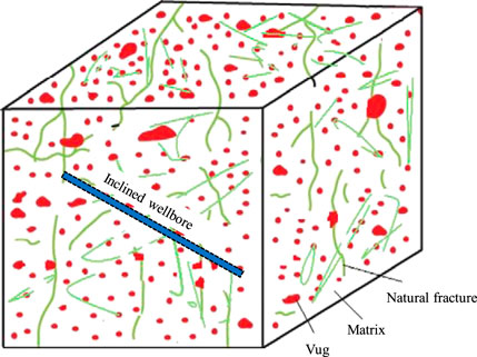
FIGURE 1. Fractured-vuggy carbonate reservoirs scheme (Modified after Nie et al., 2012).
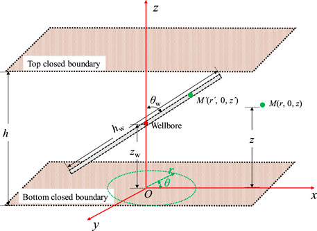
FIGURE 2. The scheme of an inclined well (Modified after Dong et al., 2018).
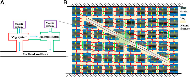
FIGURE 3. Flow scheme of FVCHRs with triple-porosity dual-permeability behavior.
Mathematical Modeling
Based on the scheme of an inclined well as shown in Figure 2, the mathematical model of the inclined well is established in FVCHRs. In order to help reader to understand coordinate system as shown in Figure 2, three different views of an inclined well in top and bottom closed boundary are given in Figure 4.
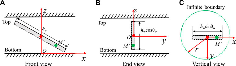
FIGURE 4. Three different view in Figure 2 (Modified after Nie et al., 2012). (A) Comparison with Guo et al.’ result. (B) Comparison with Camacho-Velázquez et al. result.
According to the state equation, the motion equation and the continuity equation, the differential equation of matrix, vug and natural fracture systems is established in FVCHRs (Camacho-Velázquez et al., 2005). Inclined well could be regarded as a line source in 3D space. Therefore, to obtain solutions for inclined well, we must establish a 3D point source model. Then we can get a surface source solution through point source integral method.
(1) The two-dimensional seepage differential equation of natural fracture system can be described as:
(2) The two -dimensional seepage differential equation of vug system can be described as:
(3) The seepage differential equation of matrix system can be described as:
(4) Initial condition can be described as:
(5) Inner condition boundary can be described as:
(6) Outer condition boundary can be described as:
where:
For convenience of derivation, the relevant dimensionless variables are defined in Table 1: Laplace transformation with respect to
where:
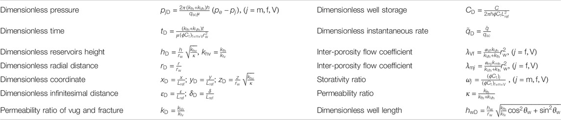
TABLE 1. Dimensionless variables definition.
According to the dimensionless definition, the dimensionless forms of the differential equation and boundary conditions can be given by:
where:
By employing the finite cosine Fourier transform with respect to
where:
By solving Eq. 10, the general point source solution for the top and bottom closed boundary, constant production and infinite lateral boundary FVCHRs with triple-porosity dual-permeability behavior can be obtained through Laplace transform and Fourier transform methods (Liu et al., 2019; Wang et al., 2019; Xue et al., 2019):
where:
It is useful to express the Eq. 12 in polar coordinates, let the polar coordinates of the points
where:
Although Gringarten et al. (1974) pointed out that the wellbore pressure of horizontal well and infinite conductivity hydraulic fractured well can be calculate by an equivalent-pressure point
In order to enhance calculation speed of the inclined well, Ozkan and Raghavan (2000) provides an efficient algorithm to compute transient pressure responses of inclined wells in Laplace domain. The principle of convolution can be used to obtain solution with the effects of wellbore storage and skin factor, which could be given by
where:
The solution of inclined well in real domain for FVCHRs with triple-porosity dual-permeability behavior is obtained by employing Stehfest (1970) numerical inversion algorithm. Dimensionless pressure and its derivative type curves are drawn analyzed.
Model Verification
Compared with vertical wells and horizontal wells, wellbore pressure solution of the inclined well is more universal, so our work expands analytical solution of vertical well and horizontal well in FVCHRs with triple-porosity dual-permeability behavior. However, in order to verify the correctness of our model and solution, the simplified model of this paper is compared with analytical solution of horizontal well for FVCHRs with triple-porosity dual-permeability behavior (Guo et al., 2012) and vertical well for FVCHRs with triple-porosity dual-permeability behavior (Camacho-Velázquez et al., 2005).
Guo et al. (2012) established the mathematical model of the horizontal well under condition of different outer boundary in FVCHRs with triple-porosity dual-permeability behavior. What is different with our model is that they assumed that fluid of the naturally fractured and the matrix system are directly flow into the wellbore, inter-porosity flow from matrix to fracture and inter-porosity flow from vug to matrix and fracture is considered. In order to make verification result reliable, if parameters
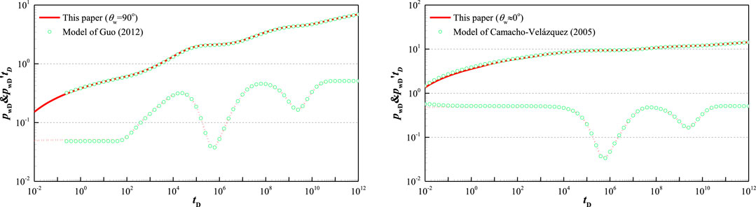
FIGURE 5. Comparison with Guo et al. (2012) and Camacho-Velázquez et al. (2005) models (
Camacho-Velázquez et al. (2005) established the mathematical model of the vertical well in FVCHRs with triple-porosity dual-permeability behavior. It is assumed that fluid of the fracture and the vug system are directly flow into the wellbore. Inter-porosity flow from vug to fracture and inter-porosity flow from matrix to vug and fracture is considered, which is same with our assumption. If inclination angle of wellbore is less than 5° and well is penetrated fully, we can think that our model is equal to vertical well. Other common parameters are same and their values are:
By comparing with horizontal and vertical well in FVCHRs with triple-porosity dual-permeability behavior, the results reached a good agreement, which verifies the correctness of our model and solution.
Type Curve and Sensitivity of Parameters
Type Curve
Figure 6 shows type curves of dimensionless pressure and its derivative of inclined well with dual-permeability behavior. According to the characteristic of the dimensionless pressure derivative curve, the type curve of inclined well can be divided into eight flow regimes for FVCHRs with triple-porosity dual-permeability behavior, which mainly includes well storage regime, skin effect regime, early vertical radial flow regime (Figure 7A), top and bottom boundary reflection (Figure 7B), linear flow regime (Figure 7C), inter-porosity flow and pseudo-radial flow regime (Figure 7D).
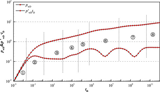
FIGURE 6. Pressure transient type curve of inclined well in FVCHRs with triple-porosity dual-permeability behavior (
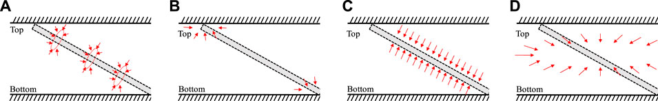
FIGURE 7. Main regime flow schemes for inclined well.
Regime①: Wellbore storage regime. During the pure wellbore storage, pressure and its derivative curves coincide and is a unit-slope straight line.
Regime②: Skin effect regime. Due to consideration of skin, pressure derivative curve looks like a “hump.”
Regime③: Early vertical radial flow regime. Pressure derivative curve is a constant value horizontal line in log-log plot (Figure 7A).
Regime④: Top and bottom boundary reflection regime. Pressure derivative curve take on a small step in log-log plot. However, this stage may disappear because of change of the length of wellbore and inclination angle of wellbore (Figure 7B).
Regime⑤: Linear flow regime. Pressure derivative curve is 1/2-slope straight line in log-log plot. Shorter well length lead to disappearance of 1/2-slope straight line (Figure 7C).
Regime⑥: Inter-porosity flow from vug to fracture. Because vug permeability is better than matrix permeability, inter-porosity flow from vug to fracture appear firstly. The curve of pressure derivative is V-shaped.
Regime⑦: Inter-porosity flow from matrix to vug and fracture. The curve of pressure derivative is V-shaped, which is controlled by parameters ωm and ωv.
Regime⑧: Pseudo-radial flow regime. Inter-porosity flows have already finished and the curve of pressure derivative is a 0.5-value horizontal line in log-log plot (Figure 7D).
Sensitivity of Parameters
Figure 8 shows type curve affected by length of inclined well in FVCHRs with triple-porosity dual-permeability behavior. Because short inclined well length can decrease contract area between reservoirs and wellbore, the short inclined well length can increase pressure loss that fluid flows into wellbore. Therefore, short inclined well length can lead to high position of pressure curve in the whole flow regime in log-log plot and make top and bottom boundary reflection regime disappear and spherical flow characteristic more obvious in pressure derivative curve.
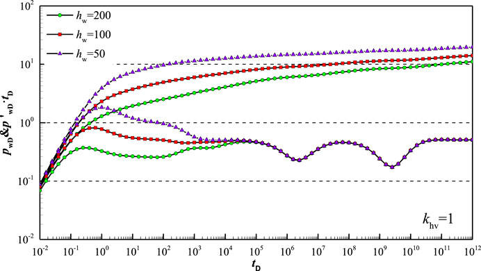
FIGURE 8. Type curve affected by length of inclined well
Figure 9 shows type curve affected by inclination angle in FVCHRs with triple-porosity dual-permeability behavior. It is assumed that length of inclined well keep constant when inclination angle changes. The large inclination angle change can only lead to disappearance of the top and bottom boundary reflection regime of pressure derivative curve without consideration of anisotropy (Figure 9A). However, if the inclined well is penetrated fully, inclination angle has a more effect on pressure and its derivative curves than inclined well penetrated partly. With the increasing of inclination angle length of inclined well become length, which leads to low position of pressure curve in whole regime and low position of pressure derivative curve during early vertical radial flow regime (Figure 9B).
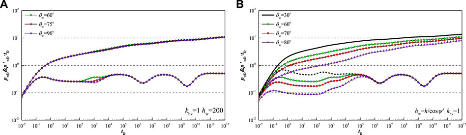
FIGURE 9. Type curve affected by inclination angle of well
Figure 10 shows type curve affected by vug storativity ratio in FVCHRs with triple-porosity dual-permeability behavior. According the flow model shown Figure 3A, fluid of the vug system do not flow into fracture, but also flow into wellbore directly. Therefore, as shown in Figure 10, small vug storativity ratio can make the second V-shaped of the pressure derivative curve become more and more deep while the first V-shaped become more and more shallow.
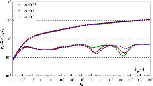
FIGURE 10. Type curve affected by parameter
Figure 11 shows type curve affected by fracture storativity ratio in FVCHRs with triple-porosity dual-permeability behavior. According the flow model shown Figure 3A, fluid of fracture system only flow into wellbore directly. Therefore, as is shown in Figure 11, fracture storativity ratio has an influence on the first V-shaped. The first V-shaped become more and more deeply with the decrease of fracture storativity ratio. The position of pressure curve become higher during vertical radial flow regime and top and bottom boundary reflection regime.
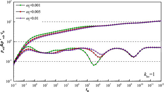
FIGURE 11. Type curve affected by parameter
Figure 12 shows type curve affected by inter-porosity flow coefficient
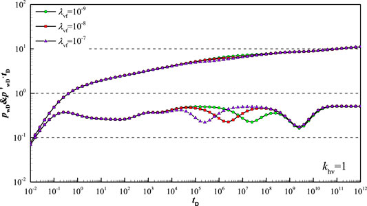
FIGURE 12. Type curve affected by parameter
Figure 13 shows type curve affected by inter-porosity flow coefficient
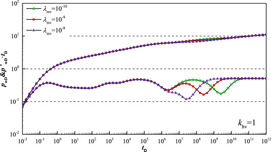
FIGURE 13. Type curve affected by parameter
Figure 14 shows type curve affected by inter-porosity flow coefficient
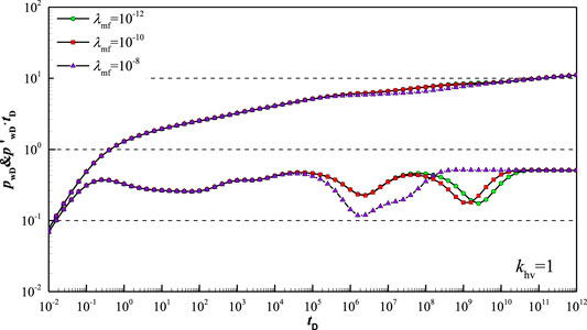
FIGURE 14. Type curve affected by parameter
Figure 15 shows type curve affected by permeability ratio
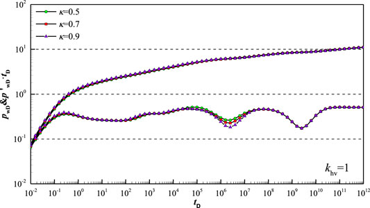
FIGURE 15. Type curve affected by parameter
Figure 16 shows type curve affected by permeability ratio
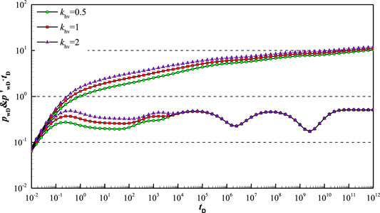
FIGURE 16. Type curve affected by parameter
Conclusion
It is assumed that fluid of vug system and fracture system flows into incline wellbore directly, and inter-porosity flow from vug system to fracture system and inter-porosity flow from matrix system to vug and fracture system is considered. Pressure transient mathematical model of inclined well is established and solved by employing Laplace transform and finite cosine Fourier transform for FVCHRs with triple-porosity dual-permeability behavior. The following conclusions can be drawn:
(1) A new analytical model was established to analysis pressure transient behavior of inclined well in FVCHRs with triple-porosity dual-permeability behavior.
(2) The model was validated by comparing our simplified model with model of horizontal well and vertical well of FVCHRs with triple-porosity dual-permeability behavior. Result reach a good agreement.
(3) Eight flow regimes, according to the characteristic of pressure derivative curve, can be recognized, and flow characteristic of each flow regime was described in detail.
(4) The effect of some vital parameters (such as well length, well inclination angle and permeability ratio, etc.) on pressure and its derivative curves are analyzed.
Data Availability Statement
The raw data supporting the conclusions of this article will be made available by the authors, without undue reservation.
Author Contributions
XL and ZM designed the research; SQ and XT built the model; SQ and YX analyzed and simulated experimental data; ZM, TD and SQ were in charge of revision and writing.
Funding
This article was supported by the National Natural Science Foundation of China (51704246) and Sichuan Science and Technology Project (18SYXHZ0090).
Conflict of Interest
The authors declare that the research was conducted in the absence of any commercial or financial relationships that could be construed as a potential conflict of interest.
References
Abadassah, D., and Ershaghi, I. (1986). Triple-porosity systems for representing naturally fractured reservoirs. SPE Form. Eval. 1 (2), 113–127. doi:10.2118/13409-pa
Camacho-Velázquez, R., Vásquez-Cruz, M, Castrejón-Aivar, R., and Arana-Ortiz, V. (2005). Pressure-transient and decline-curve behavior in naturally fractured vuggy carbonate reservoirs. SPE Reservoir Eval. Eng. 8 (2), 95–111. doi:10.2118/77689-pa
Cinco-Ley, H., Miller, F. G., and Ramey, H. J. (1975). Unsteady-State pressure distribution created by a directionally drilled well. J. Petrol. Technol. 27, 1392–1400. doi:10.2118/5131-PA
Cinco-Ley, H., Ramey, H. J., and Miller, F. (2007). “Pseudo-skin factors for partially-penetrating directionally-drilled wells,” in Fall meeting of the society of petroleum engineers of AIME, Dallas, TX, 28 September–1 October. doi:10.2523/5589-ms
Corbett, P. W.M., Geiger, S., Borges, L., Garayev, M., Gonzalez, J. G., and Valdez, C. (2010). “Limitations in numerical well rest modelling of fractured carbonate rocks.” in 72nd European association of geoscientists and engineers conference and exhibition 2010: a new Spring for geoscience, Barcelona, Spain, 14–17 June, 1135–1145. doi:10.2523/130252-ms
Dong, W., Wang, X., and Wang, J. (2018). A new skin factor model for partially penetrated directionally-drilled wells in anisotropic reservoirs. J. Petrol. Sci. Eng. 161, 334–348. doi:10.1016/j.petrol.2017.11.062
Du, X., Lu, Z, Li, D, Xu, Y, Li, P, and Lu, D (2019). A novel analytical well test model for fractured vuggy carbonate reservoirs considering the coupling between oil flow and wave propagation. J. Petrol. Sci. Eng. 173, 447–461. doi:10.1016/j.petrol.2018.09.077
Feng, G. Q., and Liu, Q.-G. (2015). Pressure transient behavior of a slanted well with an impermeable fault. J. Hydrodyn. 26 (6), 980–985. doi:10.1016/S1001-6058(14)60108-6
Gao, B., Huang, X., Yao, J., Lv, X., and Wu, Y. (2016). Pressure transient analysis of a well penetrating a filled cavity in naturally fractured carbonate reservoirs. J. Petrol. Sci. Eng. 145, 392–403. doi:10.1016/j.petrol.2016.05.037
Gringarten, A. C., and Ramey, H. J. (1973). Use of source and green’S functions in solving unsteady-flow problems in reservoirs. Soc. Pet. Eng. AIME J. 13 (5), 285–296. doi:10.2118/3818-PA
Gringarten, A. C., Ramey, H. J., and Raghavan, R. (1974). Unsteady-state pressure distributions created by a well with a single infinite-conductivity vertical fracture. Soc. Pet. Eng. AIME J. 14 (4), 347–360. doi:10.2118/4051-pa
Guo, J. C., Nie, R. S., and Jia, Y. L. (2012). Dual permeability flow behavior for modeling horizontal well production in fractured-vuggy carbonate reservoirs. J. Hydrol. 464–465, 281–293. doi:10.1016/j.jhydrol.2012.07.021
Jia, Y. L., Fan, X. Y., Nie, R. S., Huang, Q. H., and Jia, Y. L. (2013). Flow modeling of well test analysis for porous-vuggy carbonate reservoirs. Transp. Porous Media 97 (2), 253–279. doi:10.1007/s11242-012-0121-y
Kuchuk, F., and Biryukov, D. (2014). Pressure-transient behavior of continuously and discretely fractured reservoirs. SPE Reservoir Eval. Eng. 17 (1), 82–97. doi:10.2118/158096-PA
Kui, M. Q., Tan, X. H., Li, X. P., and Cai, J. (2017). Analysis on unsteady flow for power-law fluids in dual fractal media. J. Porous Media 20 (12), 1071–1086. doi:10.1615/JPorMedia.v20.i12.20
Liu, J., Bodvarsson, G. S., and Wu, Y. S. (2003). Analysis of flow behavior in fractured lithophysal reservoirs. J. Contam. Hydrol. 62–63, 189–211. doi:10.1016/S0169-7722(02)00169-9
Liu, Q., Xu, Y., Peng, X., Liu, Y., and Qi, S. (2019). Pressure transient analysis for multi-wing fractured wells in dual-permeability hydrocarbon reservoirs. J. Petrol. Sci. Eng. 180, 278–288. doi:10.1016/j.petrol.2019.05.013
Nie, R. S., Meng, Y. F., Guo, J. C., and Jia, Y. L. (2012). Modeling transient flow behavior of a horizontal well in a coal seam. Int. J. Coal Geol. 92, 54–68. doi:10.1016/j.coal.2011.12.005
Ozkan, E., and Raghavan, R. (1991). New solutions for well-test-analysis problems. Part 2. Computational considerations and applications. SPE Form. Eval. 6 (3), 369–378. doi:10.2118/18616-PA
Ozkan, E., and Raghavan, R. (2000). A computationally efficient, transient-pressure solution for inclined wells. SPE Reservoir Eval. Eng. 3 (5), 414–425. doi:10.2118/66206-PA
Ozkan, E., and Raghavan, R. (2004). New solutions for well-test-analysis problems: Part 1-Analytical Considerations (includes associated papers 28666 and 29213). SPE Form. Evaluation. 6 (03), 359–368. doi:10.2118/18615-PA
Ozkan, E., Yildiz, T., and Raghavan, R. (1999). “Pressure-transient analysis of perforated slant and horizontal wells,” in SPE Annual Technical Conference and Exhibition, Houston, TX, October 3–6, 1999.
Pang, Y., Hu, X, Wang, S, Chen, S., Soliman, M. Y., and Deng, H. (2020). Characterization of adsorption isotherm and density profile in cylindrical nanopores: modeling and measurement. Chem. Eng. J. 396, 125212. doi:10.1016/j.cej.2020.125212
Pruess, K., and Narasimhan, T. N. (1985). Practical method for modeling fluid and heat flow in fractured porous media. Soc. Petrol. Eng. J. 25 (1), 14–26. doi:10.2118/10509-pa
Raghavan, R, and Ozkan, E. (2017). A method for computing unsteady flows in porous media. Oxon, UK: Routledge. doi:10.1201/9781315136387
Song, F., Bo, L., Zhang, S., and Sun, Y. (2019). Nonlinear flow in low permeability reservoirs: modelling and experimental verification. Adv. Geo-Energy Res. 3, 76–81. doi:10.26804/ager.2019.01.06
Stehfest, H. (1970). Algorithm 368: numerical inversion of Laplace transforms [D5]. Commun. ACM 13 (1), 47–49.
Sun, Q., Zhang, N., Mohamed, F., and Wang, Y. (2018). Structural regeneration of fracture-vug network in naturally fractured vuggy reservoirs. J. Petrol. Sci. Eng. 165, 28–41. doi:10.1016/j.petrol.2017.11.030
Tan, X. H., Jiang, L., Li, X. P., Zhang, B. J., and Li, X. C. (2018). Flow model of a multi-stage hydraulic fractured horizontal well based on tree-shaped fractal fracture networks. J. Petrol. Sci. Eng. 169, 494–503. doi:10.1016/j.petrol.2018.06.008
Tontiwachwuthikul, P., Chan, C. W., Zeng, F., Liang, Z., Sema, T., and Chao, M. (Forthcoming 2020). Recent progress and new developments of applications of artificial intelligence (AI), knowledge-based systems (KBS), and machine learning (ML) in the petroleum industry. Petroleum. doi:10.1016/j.petlm.2020.08.001
Van Everdingen, A. F., and Hurst, W. (1949). The application of the Laplace transformation to flow problems in reservoirs. J. Petrol. Technol. 1 (12), 305–324. doi:10.2118/949305-g
Wang, L., Cheng, D., Xiang, L., Chen, X., and Xia, Z. (2019). Pressure transient analysis for asymmetrically fractured wells in dual-permeability organic compound reservoir of hydrogen and carbon. Int. J. Hydrog. Energy 44 (11), 5254–5261. doi:10.1016/j.ijhydene.2018.08.082
Wang, L., Wang, X., Luo, E., and Wang, J. (2014). Analytical modeling of flow behavior for wormholes in naturally fractured–vuggy porous media. Transp. Porous Media 105 (3), 539–558. doi:10.1007/s11242-014-0383-7
Wang, M., Fan, Z., Dong, X., Song, H., Zhao, W., and Xu, G (2018). Analysis of flow behavior for acid fracturing wells in fractured-vuggy carbonate reservoirs. Math. Probl. Eng. 2018 (PT. 3), 6431910. doi:10.1155/2018/6431910
Wang, Q., Yang, S., Glover, P. W. J., Lorinczi, P., Qian, K., and Wang, L. (2020). Effect of pore-throat microstructures on formation damage during miscible CO2 flooding of tight sandstone reservoirs. Energy Fuels 34 (4), 4338–4352. doi:10.1021/acs.energyfuels.0c00158.
Warren, J.E., and Root, P. J. (1963). The behavior of naturally fractured reservoirs. Soc. Petrol. Eng. J. 3 (3), 245–255. doi:10.2118/426-pa
Wu, Y. S., Liu, H. H., and Bodvarsson, G. S. (2004). A triple-continuum approach for modeling flow and transport processes in fractured rock. J. Contam. Hydrol. 73 (1–4), 145–179. doi:10.1016/j.jconhyd.2004.01.002
Wu, Y. S., Yuan, D., Kang, Z., and Fakcharoenphol, P. (2011). A multiple-continuum model for simulating single-phase and multiphase flow in naturally fractured vuggy reservoirs. J. Petrol. Sci. Eng. 78 (1), 13–22. doi:10.1016/j.petrol.2011.05.004
Xing, C., Yin, H., Liu, K., Li, X, and Fu, J. (2018). Well test analysis for fractured and vuggy carbonate reservoirs of well drilling in large scale cave. Energies 11 (1), 1–15. doi:10.3390/en11010080
Xue, L., Chen, X., and Wang, L. (2019). Pressure transient analysis for fluid flow through horizontal fractures in shallow organic compound reservoir of hydrogen and carbon. Int. J. Hydrog. Energy 44 (11), 5245–5253. doi:10.1016/j.ijhydene.2018.08.084
Yildiz, T., and Ozkan, E. (1999). Pressure-transient analysis for perforated wells. SPE J. 4. doi:10.2118/56878-PA
Keywords: inclined well, fractured-vuggy carbonate hydrocarbon reservoirs, triple-porosity dual-permeability, inter-porosity flow, pressure transient
Citation: Qi S-Z, Tan X-H, Li X-P, Meng Z, Xu Y-J and Tang D (2020) Transient Pressure Analysis of Inclined Well in Continuous Triple-Porosity Reservoirs With Dual-Permeability Behavior. Front. Energy Res. 8:601082. doi: 10.3389/fenrg.2020.601082
Received: 31 August 2020; Accepted: 02 October 2020;
Published: 01 December 2020.
Edited by:
Kaiqiang Zhang, Imperial College London, United KingdomCopyright © 2020 Qi, Tan, Li, Meng, Xu and Tang. This is an open-access article distributed under the terms of the Creative Commons Attribution License (CC BY). The use, distribution or reproduction in other forums is permitted, provided the original author(s) and the copyright owner(s) are credited and that the original publication in this journal is cited, in accordance with accepted academic practice. No use, distribution or reproduction is permitted which does not comply with these terms.
*Correspondence: Sheng-Zhi Qi, ctfy742@163.com; Xiao-Hua Tan, xiaohua-tan@163.com