Article

Effect of the Substrate Biasing on the Structure and Properties of Tantalum Coatings Deposited Using HiPIMS in Deep Oscillations Magnetron Sputtering Mode

1
Department of Mechanical Engineering, CEMMPRE, University of Coimbra, Rua Luis Reis Santos, 3030-788 Coimbra, Portugal
2
LED&Mat-IPN, Laboratório de Ensaios Desgaste e Materiais, Instituto Pedro Nunes, Rua Pedro Nunes, 3030-199 Coimbra, Portugal
*
Author to whom correspondence should be addressed.
Metals 2020, 10(12), 1618; https://doi.org/10.3390/met10121618
Submission received: 10 November 2020 / Revised: 28 November 2020 / Accepted: 28 November 2020 / Published: 1 December 2020

Abstract

:
The influence of energetic ion bombardment on the properties of tantalum coatings was studied. To achieve such energetic ion bombardment during the deposition process of tantalum coatings, a combination of deep oscillation magnetron sputtering (DOMS), an ionized physical vapour deposition technique, with substrate biasing was used. The substrate biasing was varied between 0 and −120 V. In this work, the structure (XRD), microstructure (SEM), surface morphology (AFM) and hardness, and Young’s modulus (nanoindentation) of the coatings were characterized. The results show with the use of such conditions it was possible to deposit a pure α-Ta (the most desired at industrial level) with improved mechanical properties (hardness equal to 22.4 GPa and Young’s modulus equal to 235 GPa). The roughness of the Ta coatings decreases up to values of about 1 nm with an increase of substrate biasing. It was possible to deposit very dense Ta coatings with 2 µm of thickness. Therefore, these results are significantly different than in previous works, offering Ta coatings with a combination of very interesting properties.

1. Introduction

As refractory metal tantalum with its unique characteristics and attractive properties has been widely used in wear protection and high temperature applications, e.g., jet engines, gun bore protection and nuclear reactors [1,2,3,4,5,6]. Ta material presents two distinctive crystallographic phases, on one hand, a stable bcc α-phase and, on the other hand, a metastable tetragonal β-phase. From the two, the α-phase Ta is the most desired at industrial level due to its toughness and ductility. The β-phase Ta is hard and brittle which may compromise the use of Ta material in many applications. Typically, bulk tantalum metal has the α-phase structure, however, both single and mixed phases of α-phase structure and β-phase structure develops in coatings [1]. Based on the state of the art, different parameters can be tuned in order to avoid the β-phase Ta growth, e.g., substrate material, energetic ion bombardment, substrate temperature, or sputtering gas [7,8,9,10,11]. Among the different parameters, it was observed that the use of energetic ion bombardment during the coating growth played an important role in the structure and properties of the produced Ta coatings [7]. These Ta coatings are widely produced by direct current magnetron sputtering (DCMS), however, the ionization degree of the sputtered material is very low (around 1% to 3%) in this technique, and therefore the only method to reach such high energetic ion bombardment during film growth is by using a substrate biasing. Recently, the development of new magnetron sputtering deposition techniques which allow to generate highly ionized fluxes of sputtered material brought an increased control over the energetic ion bombardment during coating deposition. High-power impulse magnetron sputtering (HiPIMS) [12,13,14,15], and modulated pulsed power magnetron sputtering (MPPMS) [16,17,18] are two of these recent developments. The deposition of Ta coatings by these techniques is already well established. Alami et al. pointed out the capabilities of HiPIMS in the production of α-phase Ta due to its additional control over the energetic ion bombardment [19]. Likewise, Lin et al. proved the influence of the energetic ion bombardment of MPPMS on the structure of Ta coatings [20]. Recently, a new variant of the HiPIMS process was developed called deep oscillation magnetron sputtering (DOMS) [21,22,23,24,25]. This deposition process uses a series of short pulses that form a macropulse. These short pulses reach a very high voltage (even higher than typical voltages achieved in HiPIMS and MPPMS process) and then decay, reaching zero. Detailed description of the macropulse configuration in DOMS is provided elsewhere [21]. So, it is expected that the combination of superior energetic ion bombardment in DOMS with the use of substrate biasing (key parameter in Ta production) can be utilized to improve the structure and properties of tantalum coatings. In this work, a group of tantalum coatings were deposited by DOMS with increasing substrate biasing. The structure, morphology, and mechanical properties of tantalum coatings were characterized.

2. Materials and Methods

Tantalum coatings were deposited on Si (100) substrates using a DOMS power supply (HiPIMS Cyprium ™plasma generator, Zpulser Inc., Mansfield, MA, USA). Figure 1 displays a typical DOMS discharge voltage and current used in this work.
Prior to all depositions the substrates were ultrasonically cleaned in a sequence of acetone and ethanol solutions baths, for 15 min each. They were then placed in the deposition chamber, made from a high grade stainless steel with 400 mm × 400 mm × 400 mm dimensions. The substrate-to-target was kept at 80 mm and substrate rotation was equal to 23.5 rpm for all depositions. The used target consisted in a square shape 99.95% purity Ta target with dimensions of 150 mm × 150 mm and 10 mm of thickness. A base pressure lower than 3 × 10⁻⁴ Pa was achieved before all depositions. The working pressure was kept at 0.7 Pa by maintaining the constant flow rate of the sputter gas at 15 SCCM (Ar-99.999%). The deposition time was changed in order to achieve 2 µm of coating thickness. In all depositions, the voltage on-time (ton), oscillation period (T), and pulse duration (D) were equal to 6 μs, 50 μs, and 1250 μs, respectively. On the other hand, the pulse frequency (F) was automatically adjusted by the DOMS power supply in order to keep a constant average power fixed at 1.2 kW. The peak power (Pp) is defined as the product Vp × Ip. The substrate biasing was varied between 0 and −120 V. The main DOMS deposition parameters are compiled in Table 1.
The morphology and thickness of the Ta coatings were studied by scanning electron microscopy (SEM) using a Quanta 400FEG ESEM (Waltham, Massachusetts, MA, USA). The present SEM images obtained for the cross-section and surface area in this work were obtained with a 2 kV beam. The deposition rate was calculated by dividing the coating thickness (measured by SEM) by the deposition time. The crystal structure of Ta coatings was investigated by X-ray diffraction (XRD) using a PANalytical X’Pert PRO MPD (Malvern, UK) with Cu Kα radiation (45 kV and 40 mA) with a parallel beam in θ–2θ geometry. The incident beam optics consisted of a hybrid monochromator (with a Cu W/Si mirror and a double crystal Ge (220)). A parallel plate collimator (0.7°) and Soller slits (0.004°) were attached on the path of the diffracted beam. A PIXcel detector in receiving slit mode was used for X-ray collection. The coating topography and surface roughness were observed by atomic force microscopy (AFM) using a Bruker Innova equipment (Billerica, Massachusetts, MA, USA) in contact mode on a surface area of 2 × 2 μm2. The hardness of the coatings was measured by nano-indentation using a Micro Materials Nano Tester (Wrexham, UK) with a Berkovich diamond indenter. The hardness was assessed from the load–displacement curve using the depth sensing method. Hardness measurements were done with 10 mN loads in order to ensure an indentation depth less than 10% of the coating´s thickness. 20 hardness measurements were performed on each sample.

3. Results

The deposition rate decreases with increasing substrate biasing (Figure 2). This effect occurs due to the re-sputtering of the deposited Ta atoms, a direct consequence of the bombardment of the growing coating with metal ions and the discharge gas. This effect increases with the bias voltage value.
The X-ray diffraction patterns (between 30° and 45°) of the Ta coatings deposited by DOMS with different bias voltage values are shown in Figure 3. In addition, the β (200) at 2θ = 33.69° (ICCD card 00-025-1280) and α (110) at 2θ = 38.47° (ICCD card 00-004-0788) are presented in Figure 3. The application of a substrate biasing results in the deposition of α-Ta coatings with [110] preferential orientation instead of the biphasic coating obtained without substrate biasing. The diffraction peaks corresponding to the α-Ta phase are shifted to smaller diffraction angles in relation to the standard material, which is most probably due to the formation of compression stresses in the coatings. However, the position of the peaks does not vary with the application of different bias voltage values. All Ta coatings deposited with substrate biasing show only the peak (110) of α-Ta, contrary to what was observed by Ren et al. [26]. The additional bombardment caused by applying a substrate biasing refutes the role of the substrate, contrary to the hypothesis of Feinstein et al. about favouring β-Ta nucleation in Si substrates [27], as well as the hypothesis developed by Catania et al. β phase deposition for bias voltage values below −100 V [28,29].
The cross-section and surface morphology of Ta films as a function of the substrate biasing can be seen in Figure 4. The Ta coating deposited without substrate biasing presents two different types of fracture, the upper part of the coating exhibits a ductile fracture while the lower part (close to the substrate) exhibits a brittle fracture. Myers et al. detected a similar result and attributed these different fractures types to the existence of different tantalum phases [30]. This is in agreement with the X-ray diffractions which revealed a mixed phase structure. The Ta coatings deposited with substrate biasing have a denser interlayer at its bottom, similar to what was observed for the Ta film deposited without biasing. However, the interlayer thickness is much thinner in the Ta coatings deposited with substrate biasing. As mention before, this interlayer was associated with the deposition of the β-Ta phase. However, this phase was not detected in the deposited films with substrate biasing (Figure 3). The cross-section SEM images of the deposited Ta coatings present an evident evolution of the coating microstructure with the application of a substrate biasing. Although is still observe some traces of columns in the cross-section for the coating with a substrate biasing of −120 V, it has a much more compact and denser microstructure when compared to the other Ta coatings. With the exception of this coating, which is on the threshold between Zone 2 and Zone T, all the other Ta coatings correspond to Zone 2 in the SZD diagram proposed by André Anders [31]. A similar evolution in coating microstructure was observed by Lin et al. [20]. The increase of the bias voltage also changes the surface morphology. With the increase of the bias voltage value, the tightly packed granular structures give rise to the formation of filamentary structures embedded in a homogeneous matrix, as observed by Ren et al. [26] in deposited Ta coatings with higher bias voltages than those used in this work. Although the amount of filamentary structures increases with the substrate biasing, their dimensions decrease in such a way that they are no longer seen on the surface of the deposited coating with the highest bias voltage value (−120 V). Although the formation of filamentary structures is mentioned in some works in the literature, associated with the application of a substrate biasing during depositions [26,32], a satisfactory explanation for its formation has not yet been found.
The images of the surface of the Ta coatings obtained by AFM (Figure 5) confirm the evolution of the surface morphology with the application of a substrate biasing. The Ta coatings deposited with substrate biasing have a coarser surface associated with the formation of filamentary structures, although these are not clearly visible in the images. However, the roughness of the Ta coatings decreases (Figure 6), up to values of about 1 nm with an increase of substrate biasing.
The hardness and the Young’s modulus of the Ta coatings are presented in Figure 7. Typically, the α-Ta has hardness = 8–12 GPa and Young’s modulus = 203−219 GPa and the β-Ta has hardness = 18–20 GPa Young’s modulus = 215−243 GPa [30,33]. Both the hardness and the Young’s modulus of the Ta coatings are not significantly altered with the application of a substrate biasing up to −80 V. These coatings have a hardness of about 12 GPa, similar to that obtained in the deposited coating without substrate biasing. As in the case of this last coating, the hardness values are higher than those published in the literature for α-Ta, so one would expect the presence of β-Ta. However, this last phase was not detected by XRD analyses. The Ta coating deposited at a bias voltage of −120 V has the highest hardness (22.4 GPa) and Young’s modulus (235 GPa) value. This result could be due to the higher energy of the ions that bombard the substrate during the growth of the coating, giving rise to a coating with a more compact microstructure as seen in Figure 4. However, in this case, the increased substrate biasing should translate into a gradual increase in the hardness and Young’s modulus of the coatings and does not explain the sudden increase in these properties observed at −120 V as seen in Figure 7. The hardness of the deposited Ta coating with −120 V is similar to the hardness reported in the literature for the bulk β-Ta material, so the higher hardness value could correspond to the deposition of this phase in higher quantity when compared to the other deposited Ta coating. However, again, β-Ta deposition is not detected by XRD analyses.

4. Conclusions

In general, the use of a substrate biasing induces a significantly different growth mode for the Ta coatings when compared to the Ta coating deposited by DOMS without substrate biasing. This deposition mode results in the formation of filamentary structures embedded in a more homogeneous matrix. The deposition rate of Ta coatings deposited by DOMS decreases with increasing bias voltage value due to the re-sputtering of Ta atoms during film growth. The Ta coating deposited without substrate biasing has a biphasic structure of α-Ta + β-Ta. The X-ray diffractograms of the Ta coatings deposited by DOMS with substrate biasing show only the (110) diffraction peak of the α-Ta despite its mechanical properties indicating the deposition of the much harder β-Ta phase. In particular, the coating deposited with the highest bias voltage has a much higher hardness than the others and is similar to that of the bulk β-Ta material. Regardless of the deposition conditions, both phases of Ta always have a complete preferential orientation ([110] for α-Ta and [200] for β-Ta). The surface roughness decreases with increasing substrate biasing. Therefore, the combination of superior energetic ion bombardment in DOMS with the use of substrate biasing resulted in the production of the α-phase Ta (the most desired at industrial level) with improved mechanical properties (hardness equal to 22.4 GPa and Young’s modulus equal to 235 GPa).

Author Contributions

Conceptualization, J.O.; methodology, F.F.; validation, J.O. and F.F.; formal analysis, F.F.; investigation, F.F.; resources, A.C. writing—original draft preparation, F.F.; writing—review and editing, F.F.; project administration, J.O.; funding acquisition, A.C. All authors have read and agreed to the published version of the manuscript.

Funding

This research is sponsored by FEDER funds through the program COMPETE and by national funds through FCT, under the projects UIDB/00285/2020, HardRings (AAC n.°02/SAICT/2017, projeto n.°29122).

Conflicts of Interest

The authors declare no conflict of interest.

References

  1. Lee, S.; Doxbeck, M.; Mueller, J.; Cipollo, M.; Cote, P. Texture, structure and phase transformation in sputter beta tantalum coating. Surf. Coat. Technol. 2004, 177, 44–51. [Google Scholar] [CrossRef] [Green Version]
  2. Niu, Y.; Chen, M.; Wang, J.; Yang, L.; Guo, C.; Zhu, S.; Wang, F. Preparation and thermal shock performance of thick α-Ta coatings by direct current magnetron sputtering (DCMS). Surf. Coat. Technol. 2017, 321, 19–25. [Google Scholar] [CrossRef]
  3. Shiri, S.; Zhang, C.; Odeshi, A.; Yang, Q. Growth and characterization of tantalum multilayer thin films on CoCrMo alloy for orthopedic implant applications. Thin Solid Films 2018, 645, 405–408. [Google Scholar] [CrossRef]
  4. Matson, D.W.; McClanahan, E.D.; Lee, S.L.; Windover, D. Properties of thick sputtered Ta used for protective gun tube coatings. Surf. Coat. Technol. 2001, 146, 344–350. [Google Scholar] [CrossRef]
  5. Hee, A.C.; Jamali, S.S.; Bendavid, A.; Martin, P.J.; Kong, C.; Zhao, Y. Corrosion behaviour and adhesion properties of sputtered tantalum coating on Ti6Al4V substrate. Surf. Coat. Technol. 2016, 307, 666–675. [Google Scholar] [CrossRef]
  6. Yang, S.; Yang, F.; Chen, M.; Niu, Y.; Zhu, S.; Wang, F. Effect of Nitrogen Doping on Microstructure and Wear Resistance of Tantalum Coatings Deposited by Direct Current Magnetron Sputtering. Acta Metall. Sin. 2018, 55, 308–316. [Google Scholar]
  7. Ino, K.; Shinohara, T.; Ushiki, T.; Ohmi, T. Ion energy, ion flux, and ion species effects on crystallographic and electrical properties of sputter-deposited Ta thin films. J. Vac. Sci. Technol. A Vac. Surf. Films 1997, 15, 2627–2635. [Google Scholar] [CrossRef]
  8. Ellis, E.A.; Chmielus, M.; Baker, S.P. Effect of sputter pressure on Ta thin films: Beta phase formation, texture, and stresses. Acta Mater. 2018, 150, 317–326. [Google Scholar] [CrossRef]
  9. Colin, J.J.; Abadias, G.; Michel, A.; Jaouen, C. On the origin of the metastable β-Ta phase stabilization in tantalum sputtered thin films. Acta Mater. 2017, 126, 481–493. [Google Scholar] [CrossRef]
  10. Ellis, E.A.; Chmielus, M.; Han, S.; Baker, S.P. Effect of sputter pressure on microstructure and properties of β-Ta thin films. Acta Mater. 2020, 183, 504–513. [Google Scholar] [CrossRef]
  11. Hallmann, L.; Ulmer, P. Effect of sputtering parameters and substrate composition on the structure of tantalum thin films. Appl. Surf. Sci. 2013, 282, 1–6. [Google Scholar] [CrossRef]
  12. Ehiasarian, A.; New, R.; Münz, W.-D.; Hultman, L.; Helmersson, U.; Kouznetsov, V. Influence of high power densities on the composition of pulsed magnetron plasmas. Vacuum 2002, 65, 147–154. [Google Scholar] [CrossRef]
  13. Helmersson, U.; Lattemann, M.; Bohlmark, J.; Ehiasarian, A.P.; Gudmundsson, J.T. Ionized physical vapor deposition (IPVD): A review of technology and applications. Thin Solid Films 2006, 513, 1–24. [Google Scholar] [CrossRef] [Green Version]
  14. Kouznetsov, V.; Macak, K.; Schneider, J.M.; Helmersson, U.; Petrov, I. A novel pulsed magnetron sputter technique utilizing very high target power densities. Surf. Coat. Technol. 1999, 122, 290–293. [Google Scholar] [CrossRef]
  15. Lundin, D.; Sarakinos, K. An introduction to thin film processing using high-power impulse magnetron sputtering. J. Mater. Res. 2012, 27, 780–792. [Google Scholar] [CrossRef] [Green Version]
  16. Lin, J.; Moore, J.J.; Sproul, W.D.; Mishra, B.; Wu, Z. Modulated pulse power sputtered chromium coatings. Thin Solid Films 2009, 518, 1566–1570. [Google Scholar] [CrossRef]
  17. Lin, J.; Moore, J.; Sproul, W.; Mishra, B.; Rees, J.; Wu, Z.; Chistyakov, R.; Abraham, B. Ion energy and mass distributions of the plasma during modulated pulse power magnetron sputtering. Surf. Coat. Technol. 2009, 203, 3676–3685. [Google Scholar] [CrossRef]
  18. Lin, J.; Sproul, W.D.; Moore, J.J.; Wu, Z.; Lee, S.; Chistyakov, R.; Abraham, B. Recent advances in modulated pulsed power magnetron sputtering for surface engineering. Jom 2011, 63, 48–58. [Google Scholar] [CrossRef]
  19. Alami, J.; Eklund, P.; Andersson, J.M.; Lattemann, M.; Wallin, E.; Bohlmark, J.; Persson, P.; Helmersson, U. Phase tailoring of Ta thin films by highly ionized pulsed magnetron sputtering. Thin Solid Films 2007, 515, 3434–3438. [Google Scholar] [CrossRef] [Green Version]
  20. Lin, J.; Moore, J.J.; Sproul, W.D.; Lee, S.L.; Wang, J. Effect of negative substrate bias on the structure and properties of Ta coatings deposited using modulated pulse power magnetron sputtering. IEEE Trans. Plasma Sci. 2010, 38, 3071–3078. [Google Scholar] [CrossRef]
  21. Ferreira, F.; Serra, R.; Oliveira, J.; Cavaleiro, A. Effect of peak target power on the properties of Cr thin films sputtered by HiPIMS in deep oscillation magnetron sputtering (DOMS) mode. Surf. Coat. Technol. 2014, 258, 249–256. [Google Scholar] [CrossRef]
  22. Ferreira, F.; Oliveira, J.; Cavaleiro, A. CrN thin films deposited by HiPIMS in DOMS mode. Surf. Coat. Technol. 2016, 291, 365–375. [Google Scholar] [CrossRef]
  23. Lin, J.; Sproul, W.D. Structure and properties of Cr2O3 coatings deposited using DCMS, PDCMS, and DOMS. Surf. Coat. Technol. 2015, 276, 70–76. [Google Scholar] [CrossRef]
  24. Lin, J.; Wang, B.; Sproul, W.D.; Ou, Y.; Dahan, I. Anatase and rutile TiO2 films deposited by arc-free deep oscillation magnetron sputtering. J. Phys. D Appl. Phys. 2013, 46, 084008. [Google Scholar] [CrossRef]
  25. Oliveira, J.; Fernandes, F.; Ferreira, F.; Cavaleiro, A. Tailoring the nanostructure of Ti–Si–N thin films by HiPIMS in deep oscillation magnetron sputtering (DOMS) mode. Surf. Coat. Technol. 2015, 264, 140–149. [Google Scholar] [CrossRef]
  26. Ren, H.; Sosnowski, M. Tantalum thin films deposited by ion assisted magnetron sputtering. Thin Solid Films 2008, 516, 1898–1905. [Google Scholar] [CrossRef]
  27. Feinstein, L.; Huttemann, R. Factors controlling the structure of sputtered Ta films. Thin Solid Films 1973, 16, 129–145. [Google Scholar] [CrossRef]
  28. Catania, P.; Roy, R.A.; Cuomo, J.J. Phase formation and microstructure changes in tantalum thin films induced by bias sputtering. J. Appl. Phys. 1993, 74, 1008–1014. [Google Scholar] [CrossRef]
  29. Roy, R.; Catania, P.; Saenger, K.; Cuomo, J.; Lossy, R. Role of energetic atoms and ions in Ta films grown by different physical vapor deposition methods. J. Vac. Sci. Technol. B Microelectron. Nanometer Struct. Process. Meas. Phenom. 1993, 11, 1921–1927. [Google Scholar] [CrossRef]
  30. Myers, S.; Lin, J.; Souza, R.M.; Sproul, W.D.; Moore, J.J. The β to α phase transition of tantalum coatings deposited by modulated pulsed power magnetron sputtering. Surf. Coat. Technol. 2013, 214, 38–45. [Google Scholar] [CrossRef]
  31. Anders, A. A structure zone diagram including plasma-based deposition and ion etching. Thin Solid Films 2010, 518, 4087–4090. [Google Scholar] [CrossRef] [Green Version]
  32. Navid, A.; Hodge, A. Controllable residual stresses in sputtered nanostructured alpha-tantalum. Scr. Mater. 2010, 63, 867–870. [Google Scholar] [CrossRef]
  33. Shiri, S.; Odeshi, A.; Chen, N.; Feng, R.; Sutarto, R.; Yang, Q. FCC tantalum thin films deposited by magnetron sputtering. Surf. Coat. Technol. 2019, 358, 942–946. [Google Scholar] [CrossRef]
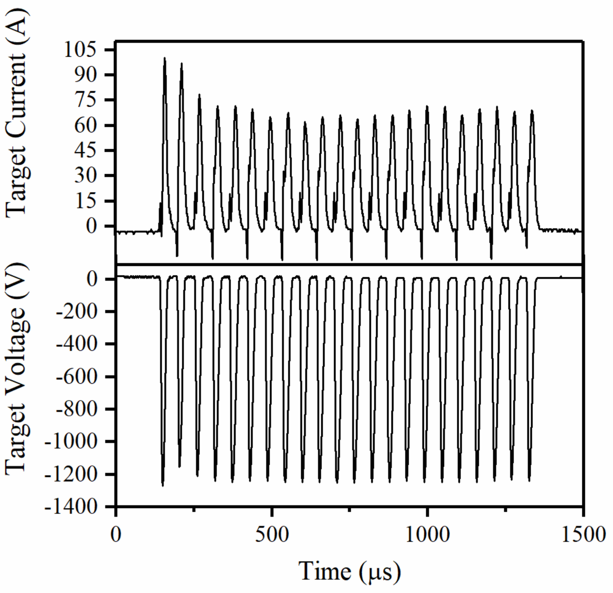
Figure 1. The target voltage and current oscillation waveforms measured during the Ta coating depositions.
Metals 10 01618 g001
Figure 2. Deposition rate and thickness of the Ta films deposited by DOMS as a function of the bias voltage.
Metals 10 01618 g002
Figure 3. X-ray diffraction patterns of the Ta films prepared by DOMS with the increase of substrate bias. On the right of the figure is inserted the signal intensity.
Metals 10 01618 g003
Figure 4. SEM cross-section and surface micrographs of the Ta coatings deposited by DOMS with a substrate biasing of: (a,b) 0 V; (c,d) −30 V; (e,f) −50 V; (g,h) −80 V; (i,j) −120 V.
Metals 10 01618 g004
Figure 5. AFM analyses of the Ta coatings deposited by DOMS with a substrate biasing of: (a) 0 V; (b) −30 V; (c) −50 V; (d) −80 V; (e) −120 V.
Metals 10 01618 g005
Figure 6. Surface roughness of the Ta coatings deposited by DOMS with different bias voltage.
Metals 10 01618 g006
Figure 7. Hardness and Young’s modulus of the Ta films deposited by DOMS with different bias voltage.
Metals 10 01618 g007
Table 1. Deposition conditions used to deposit tantalum thin films by deep oscillation magnetron sputtering (DOMS).
DCint
(V)
Vp
(V)
Ip
(A)
Pp
(kW)
Fi
(Hz)
Bias
(V)
Dep. Time
(min)
4001296101131120-115
1298100130121−30115
1285103132123−50125
1290100129119−80125
1296100130120−120144
Publisher’s Note: MDPI stays neutral with regard to jurisdictional claims in published maps and institutional affiliations.

