Anatomy and Ultrastructure of the Cyprid Temporary Adhesive System in Two Species of Acorn Barnacle


1
School of Natural and Environmental Sciences, Newcastle University, Newcastle upon Tyne, Newcastle NE1 7RU, UK
2
School of Life Sciences, University of Essex, Colchester CO4 3SQ, UK
*
Author to whom correspondence should be addressed.
J. Mar. Sci. Eng. 2020, 8(12), 968; https://doi.org/10.3390/jmse8120968
Submission received: 30 October 2020
/
Revised: 20 November 2020
/
Accepted: 24 November 2020
/
Published: 27 November 2020
(This article belongs to the Special Issue Larval Settlement on Marine Surfaces: The Role of Physico-Chemical Interactions)
Abstract
:Acorn barnacles are sessile as adults and select their settlement site as a cypris larva. Cyprids are well adapted to exploring surfaces in dynamic environments, using a temporary adhesive secreted from the antennules to adhere during this process. The temporary adhesive and the secretory structures are poorly characterized. This study used serial block-face scanning electron microscopy and three-dimensional modelling to elucidate the anatomy related to temporary adhesion. The temporary adhesive glands of two acorn barnacle species, Balanus amphitrite and Megabalanus coccopoma, were located in the proximal region of the first antennular segment, contrary to previous descriptions that placed them in the more distal second segment. The temporary adhesive systems of these acorn barnacles are therefore similar to that described for the stalked barnacle, Octolasmis angulata, although not identical. Knowledge of the true location of the temporary adhesive glands will underpin future studies of the production, composition and secretion of the adhesive.
1. Introduction
Barnacle cypris larvae use a proteinaceous adhesive secreted from their paired antennules to temporarily attach to the substratum, allowing them to effectively explore dynamic environments [1,2]. This adhesive is secreted via pores on the third antennular segment and contains the settlement-inducing protein complex (SIPC), or an analogue [3]. Temporarily adhered cyprids detach via mechanical forces, twisting their antennule and leaving behind a “footprint” of adhesive material [2,4,5,6,7]. Neither the temporary adhesive nor the structures related to its synthesis and secretion have been fully characterised in acorn barnacles.
The temporary adhesive system is distinct from the permanent adhesive used by the cyprid at the point of fixation. The morphology of the cyprid permanent adhesive system has been well characterised [8,9,10], although only basic compositional data have been obtained. The permanent adhesive is produced and stored in a pair of glands situated behind the compound eyes, with each gland serving a single antennule. When secreted, the cement is transported to the attachment disc by a single duct, which radiates at the surface to numerous pores, spreading it over a wider area.
Details regarding the composition and morphology of the temporary adhesive system are equally scant. The first description of the temporary adhesive system and its associated structures was provided by Nott and Foster [11] for Semibalanus balanoides; a boreo-arctic, intertidal, acorn barnacle (Cirripedia, Balanomorpha). They noted that the distal region of the second antennular segment contained numerous unicellular glands, arranged around the circumference of the appendage, and postulated that these may be responsible for producing the temporary adhesive [11].
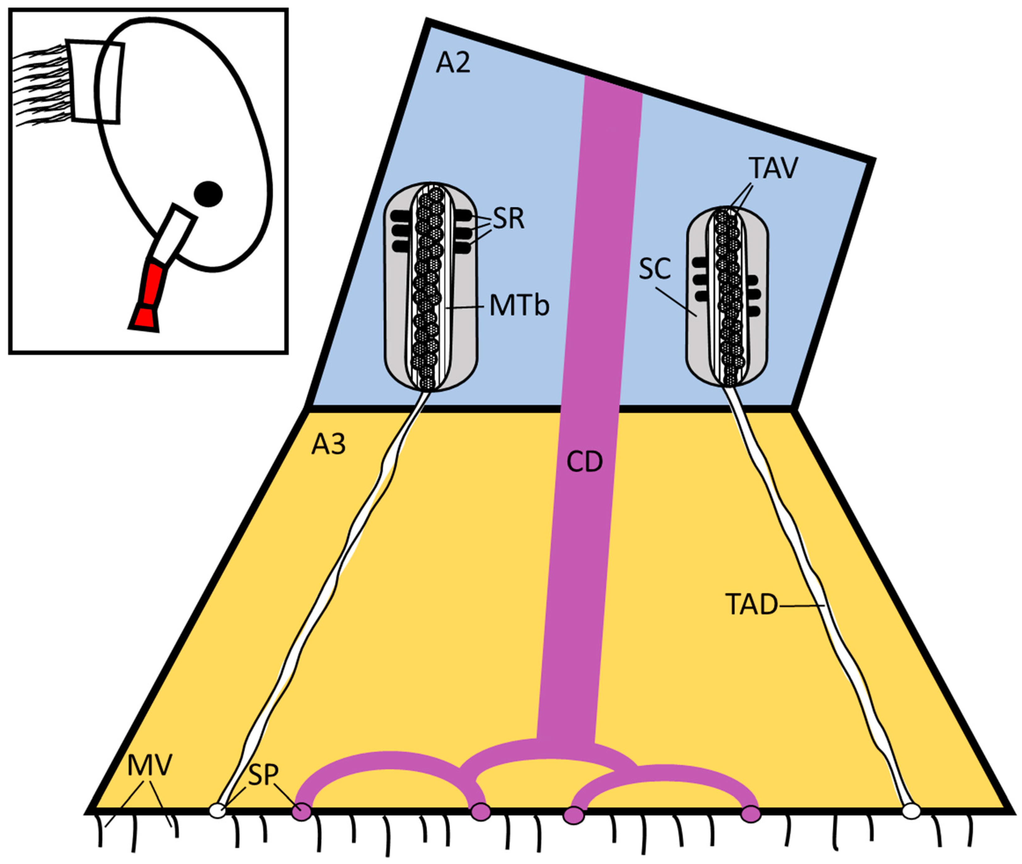
These putative glands extended into ducts that fed into pores on the surface of the third antennular segment (the attachment disc, Figure 1). Supporting rod structures and a sheath cell encapsulated the ducts in places, while the interior of the gland contained the adhesive material packed within vesicles, and numerous microtubules oriented longitudinally (Figure 1). However, these putative glands were only 1–2 µm in diameter and did not appear to contain any of the cellular structures related to protein synthesis or vesicular packaging.
A more recent study on the epibiotic stalked barnacle Octolasmis angulata [12] provided evidence of different anatomy. While many aspects of the descriptions of the two species were similar, a major difference was that the temporary adhesive glands of O. angulata were located in the anterior mantle of the cyprid behind the compound eyes, rather than in the antennules. The glands (~20 × 25 µm) comprised large, multicellular secretory cells, which contained vesicles. Ducts from the glands extended down the length of the antennules, through which the putative adhesive-containing vesicles were transported to the surface of each attachment disc [12].
As proposed by Yap et al. [12] it is conceivable that the “glands” described by Nott and Foster [11] for S. balanoides corresponded to the unicellular gland extensions observed in the distal second and third antennular segments of O. angulata. There is, therefore, the possibility that the anatomies of the adhesive systems of the two species are comparable. Certainty over the location of the adhesive glands in acorn barnacles is essential if molecular (e.g., in situ hybridisation) and immunohistochemical techniques are to be successfully applied in studies of adhesive composition.
To address this question, the present study used serial block face-scanning electron microscopy (SBF-SEM) to obtain a comprehensive series of images of the antennule, and to track the temporary adhesive system on its route from the disc surface back to to the glands. In addition, the image series allowed for three-dimensional reconstruction and modelling of the cyprid anatomy in the Microscopy Image Browser (MIB) [13]. Using these techniques, this study explored the temporary adhesive system of two acorn barnacle species, Balanus amphitrite (= Amphibalanus amphitrite) and Megabalanus coccopoma, in order to provide a basis for future investigations into the composition and secretion of the adhesive material.
2. Materials and Methods
2.1. Organism Acquisition
The cypris larvae of two species, Balanus amphitrite and Megabalanus coccopoma, were prepared for SBF-SEM. Larval production required the culturing of adult populations.
Adult broodstock of B. amphitrite was obtained from Duke University Marine Laboratory (DUML), Beaufort, North Carolina (USA). Adults were maintained in ~33 ppt artificial seawater (ASW, Tropic Marin) at 28 °C with aeration. Barnacles were fed daily with freshly hatched Artemia sp. (Varicon Aqua Solutions Ltd., Worcester, UK) nauplii supplemented with the diatoms Tetraselmis suecica and Isochrysis galbana algae at weekends. The water was also changed, and the barnacles cleaned daily.
Hatching and release of B. amphitrite nauplii were stimulated by removing the adults from water overnight and reintroducing water the following morning. They were kept in the dark, with a single source of illumination to attract the released nauplii. The nauplii were periodically collected by pipette and pooled in beakers containing T. suecica. When their number was sufficient, the nauplii were added to aerated buckets of artificial seawater at a density of no greater than 1000 larvae per litre and cultured at 28 °C on a 16 h:8 h L:D cycle. The nauplii were fed 50 mL per liter of culture of T. suecica (~1.3 × 10⁶ cells mL−1) and I. galbana (5 × 10⁶ cells mL−1) in a 3:1 ratio initially and after three days. The nauplii developed to the cyprid stage in five to six days under these conditions. Cyprids were collected from cultures by filtration with a 250 μm mesh, then transferred to dishes of ASW for storage at 4 °C until required.
Adult broodstock of M. coccopoma was also acquired from DUML and maintained as described for B. amphitrite. For the collection of larvae, buckets containing the adult M. coccopoma were checked each morning for the presence of nauplii. Nauplii were collected and cultured in the same manner as B. amphitrite. The nauplii developed to the cyprid stage in seven to eight days under these conditions. The larvae were filtered from the cultures and returned to clean buckets with fresh ASW and algal feed after four or five days. Cyprids were extracted from cultures by filtration with a 250 μm mesh. Cyprids retained on the mesh were transferred to dishes containing ASW and stored at 4 °C until required.
2.2. Sample Preparation
Cyprids of each species, (B. amphitrite, n = 6; M. coccopoma, n = 2) were fixed overnight in 2% glutaraldehyde (Agar Scientific) in 0.1 M sodium cacodylate buffer. Once fixed, the samples were processed using a heavy metal staining protocol adapted from Deerinck et al. [14]. Samples were incubated in a series of heavy metal solutions, rinsing three times for five minutes each in distilled water between steps: 3% potassium ferrocyanide in 2% osmium tetroxide for one hour, 10% thiocarbohydrazide for 20 min, 2% osmium tetroxide for 30 min, 1% uranyl acetate overnight at 4 °C, and finally lead aspartate solution (0.02 M lead nitrate in 0.03 M in aspartic acid, pH 5.5) for 30 min at 60 °C. The samples were then dehydrated through a graded series of acetone to 100% and then impregnated with increasing concentrations of Taab 812 hard resin, with three changes of 100% resin. The samples were embedded in 100% resin and left to polymerise at 60 °C for a minimum of 36 h.
The resin blocks were trimmed to approximately 0.75 mm by 0.5 mm and glued onto an aluminium pin. To reduce sample charging within the SEM, the block was painted with silver glue and sputter-coated with a 5 nm layer of gold using a Polaron SEM coating unit.
2.3. Serial Block Face-Scanning Electron Microscopy
The pin was placed into a Zeiss Sigma SEM incorporating the Gatan 3view system with DMGMS3 software, which allows sectioning of the block in situ and the collection of a series of images in the z-direction. Multiple regions of interest were imaged at variable magnification, pixel scan, section thickness and pixel resolution depending on the species (Table 1).
In the resulting z-stacks, the areas of interest were identified and segmented manually using Microscopy Image Browser (MIB, University of Helsinki) [13]. The segmentations were imported into Amira (FEI) for the construction of the 3-D models. The B. amphitrite antennule and M. coccopoma third antennular segment overlay models used 3090 and 114 sections, respectively.
3. Results
3.1. Balanus amphitrite
Cyprids of B. amphitrite were serially sectioned in the transverse plane. This orientation allowed for the best opportunity to identify the temporary adhesive ducts and track them through the antennule from the gland to the disc. However, the orientation of mounting and curvature of the antennules resulted in some sections being taken at an oblique angle. The temporary adhesive gland (one of a pair) was located in the proximal region of the first antennular segment and can be observed in Figure 2a,b.
The gland was formed of a cluster of 10–15 cells. The gland and component cells were roughly spherocylindrical in shape. The gland was ~40 µm, by 10 µm overall, while individual cells were 8–12 µm by 4–5 µm. Therefore only a few cells sat in parallel. A summary of the dimensions of key structures is presented in Table 2.
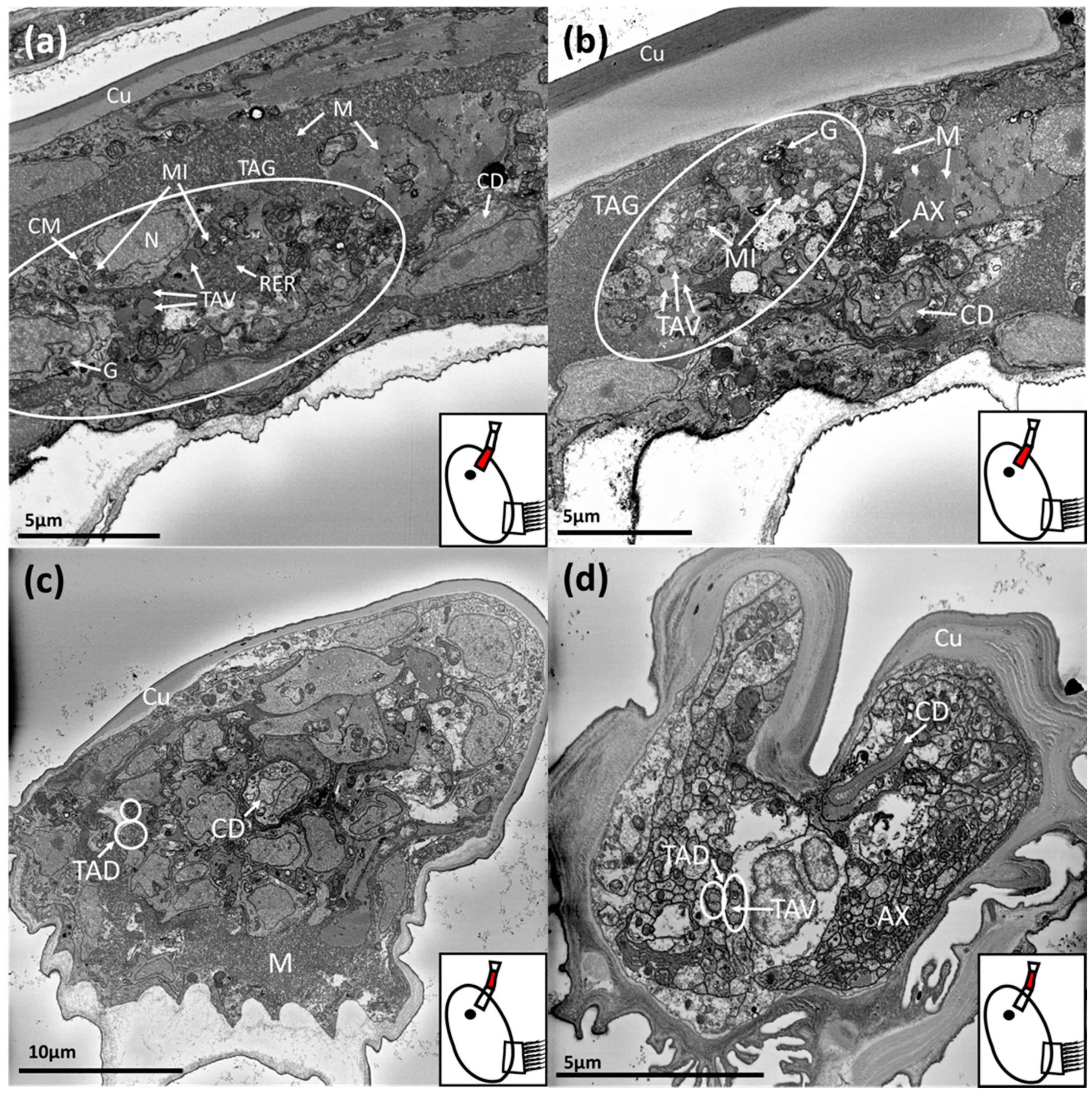
The components for protein production and packaging were present in the gland cells (Figure 2a,b). Rough endoplasmic reticulum and Golgi bodies were clearly visible, along with mitochondria. In a number of these cells, newly formed vesicles (50–200 nm) could be observed prior to their transportation down the antennule (Figure 2a,b). While the contents of the vesicles were homogenous in appearance, their size was more variable compared to those observed distally in the first and second antennular segments (Figure 2c,d). Much of the proximal first antennular segment was filled with muscle tissue, in various orientations, and the temporary adhesive gland was surrounded by muscle. The cement duct was also evident in this region and was distinct from the temporary adhesive gland as it proceeded proximally into the cephalon where the cement gland was located (Figure 2a,b). Finally, the bundled axons comprising the antennular nerve were observed, which would eventually connect with the antennular soma cluster and brain if followed proximally (Figure 2b).
Proceeding distally down the first antennular segment, the temporary adhesive gland cells transitioned into narrow ducts. The morphology of the temporary adhesive ducts remained relatively constant through the first and second antennular segments (Figure 2c,d). The temporary adhesive ducts did occasionally vary in width, however, depending on the number of vesicles contained within. For the individual illustrated, the ducts contained few vesicles for much of their length and remained narrow as a result (Figure 2c,d). The cement duct remained similar in size but became flattened as it approached the junction of the second and third antennular segments (Figure 2c,d). The axons of the antennular nerve followed a similar path through these segments, remaining clustered (Figure 2d).
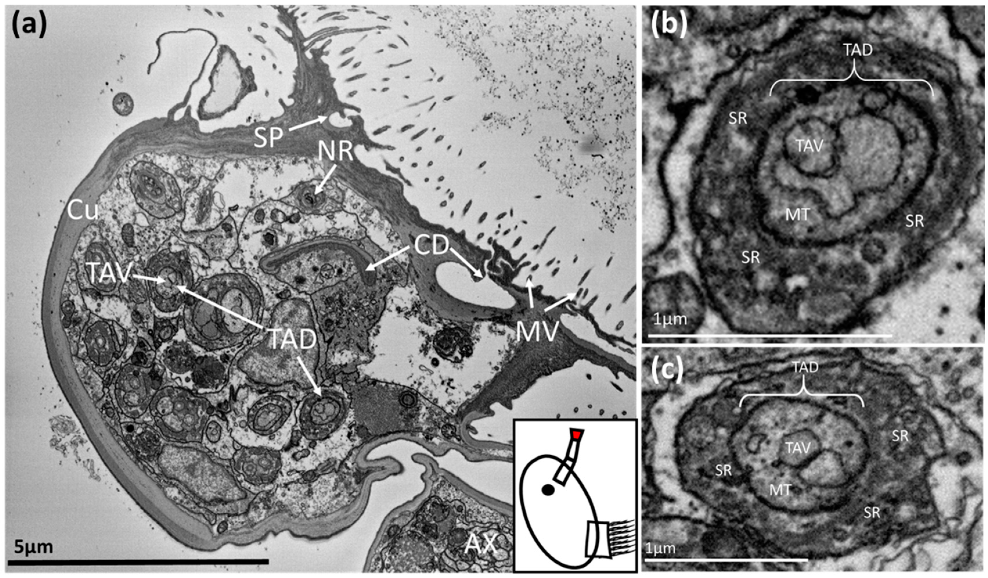
The ducts then entered the third antennular segment, or attachment disc. Here the temporary adhesive ducts expanded noticeably, becoming larger spherocylindrical structures ~1–1.5 µm in diameter with two distinct regions (Figure 3). The inner region seemed to be the transporting duct and contained numerous homogenous vesicles, each ~200 nm in diameter. These vesicles were surrounded by numerous peripheral microtubules (Figure 3b,c). The outer section was identifiable by the presence of supporting rods (Figure 3b,c). The ducts and associated elements did not appear to contain any of the cellular components required to produce and package the temporary adhesive. The number of ducts correlated with the number of cells in the temporary adhesive gland. Towards the disc surface, secretory ducts lost the supporting outer section (Figure 3a) and the secretory pores for both the temporary adhesive and cement duct could be seen terminating among the microvilli that cover the surface of the attachment disc (Figure 3a).
The cement duct remained flattened as it extended into the third antennular segment. As the specimen in Figure 1 had not begun the process of permanent adhesion, the duct was empty and appeared to have narrowed to a slit of ~3 x < 0.5 µm. Presumably, this slit would stretch and open during secretion of the permanent cement (Figure 3a). At the disc surface, this singular permanent cement duct diverged into many smaller channels to dispense the adhesive over a larger area.
Finally, the axons comprising the antennular nerve connected to neurones serving sensilla on the third and fourth antennular segments (Figure 3a).
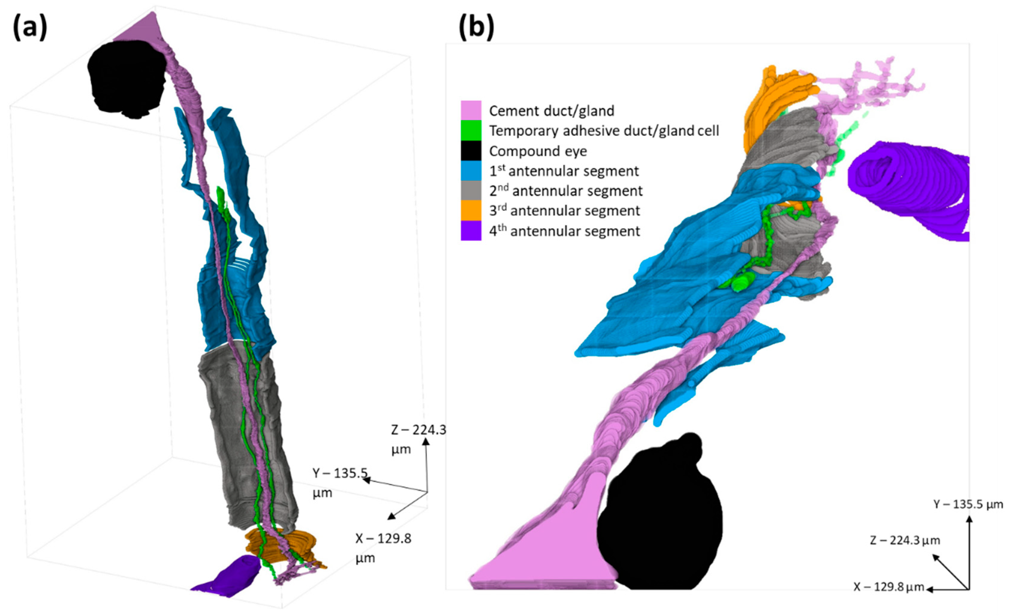
The two-dimensional images (Figure 2 and Figure 3) allowed for detailed ultrastructural observation of sections of the cyprid adhesive systems. However, the morphology of the complete system is not easy to visualise from two-dimensional sections alone. To this end, a three-dimensional reconstruction of the systems described for B. amphitrite was produced (Figure 4). Here the division of the singular cement duct into the smaller channels across the disc surface was visible, as was the position of the cement gland behind the eye. Also modelled were two of the 10–15 temporary adhesive ducts, which led back to the temporary adhesive gland in the proximal first segment, where the widening and elongation of the cells could be seen.
3.2. Megabalanus coccopoma
It seemed likely that the adhesive systems of B. amphitrite and M. coccopoma would be similar, however confirmation of the new observations in a second acorn barnacle species was nevertheless important. Since the temporary adhesive gland of B. amphitrite had already been located, the sectioning of M. coccopoma cyprids was changed from transverse to longitudinal to observe the structures from an alternate angle.
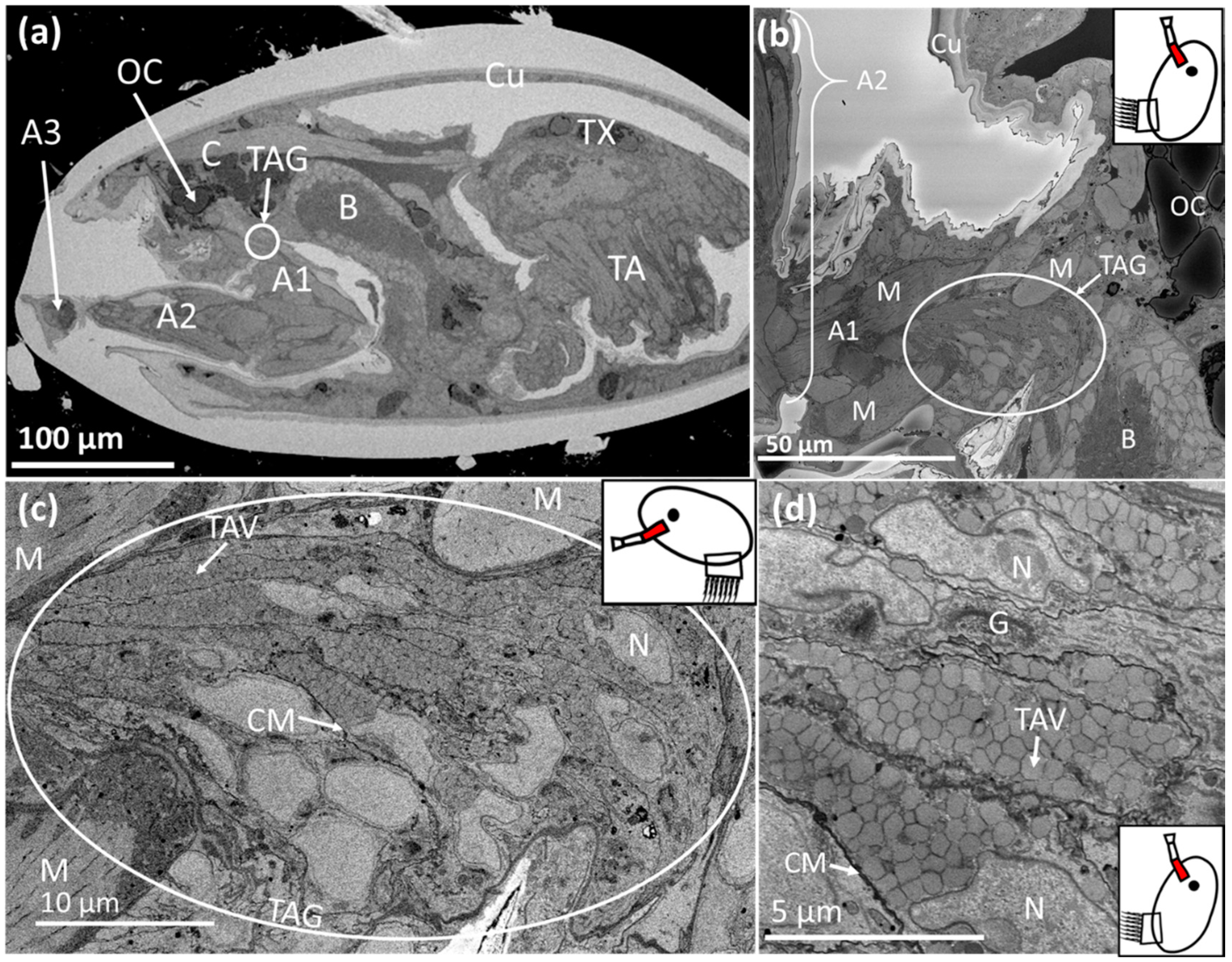
The initial longitudinal sections revealed the core structures, namely the antennule, the brain and oil cells within the anterior cephalon, and the thoracic appendages within the thorax (Figure 5a). The temporary adhesive gland was not visible in the initial imaging, however, deeper sectioning revealed its location to be consistent with that of B. amphitrite, in the proximal region of the first antennular segment (Figure 5a,b).
The temporary adhesive gland was approximately 25 × 50 µm, roughly prolate spheroid in shape and comprised of ~12 elongated cells surrounded by muscle (Figure 5b,c). A summary of the dimensions of key structures is presented in Table 2. A closer view of the gland revealed the cells to be full of homogenous vesicles of 300–400 nm in diameter (Figure 5c,d). These cells were up to 5 µm wide depending on vesicular content and 20–25 µm long. Additionally, the gland cells contained nuclei, rough endoplasmic reticulum and Golgi apparatus; the cellular structures necessary for protein production and vesicular packaging (Figure 5d). The vesicles near the Golgi apparatus were smaller and sparsely distributed, in addition to being situated on the right of the images, furthest from the antennule and transporting ducts (Figure 5c,d).
As was the case in B. amphitrite, the gland cells of M. coccopoma transitioned into ducts as they proceeded distally, narrowing to ~0.5–1 µm (Figure 6a). The duct diameter appeared to be correlated with the abundance of vesicles, with fewer vesicles resulting in a narrower duct. Other than this, the morphology of the ducts remained constant through the first and second antennular segments (Figure 6a).
Once the temporary adhesive ducts reached the third antennular segment, they expanded into larger, spherocylindrical structures on the periphery of the disc close to the surface (Figure 6b). These structures were over 1.5 µm in diameter and formed of two major sections, the vesicle-filled duct at the centre, and the supporting sheath around the outside (Figure 6b). In addition, these structures numbered approximately 12; as for the gland cells (Figure 6b,c). The temporary adhesive ducts were filled with the homogenous vesicles originally observed within the temporary adhesive gland cells. However, no vesicles were present between the spherocylindrical structures and the disc surface, where the ducts narrow and feed into secretory pores (Figure 6b). In contrast to the peripheral, singular, temporary adhesive ducts, the cement duct split into multiple sub-channels and opened out into the centre of the disc (Figure 6b).
Reconstructing the temporary adhesive ducts using three-dimensional modelling reveals that the “collecting structures” occurred in parallel pairs and were peripheral to the cement duct (Figure 6b). Unlike in B. amphitrite, the ducts took a circular route immediately following the putative collecting structures (Figure 6c) and surrounding muscle tissue.
4. Discussion
This study provides new evidence for the location of the temporary adhesive glands in acorn barnacle species and gives greater insight into the temporary adhesive system. Contrary to the findings of Nott and Foster [11], the temporary adhesive glands of Balanus amphitrite and Megabalanus coccopoma were not situated in the second antennular segment, but in the first (Figure 2a,b, Figure 4, Figure 5b and Figure 7). Instead, the ultrastructure of the acorn barnacles appeared more consistent with that of the stalked barnacle Octolasmis angulata [12], though there were some key differences.
The temporary adhesive glands of B. amphitrite and M. coccopoma possessed similar morphology and location. The glands were located in the proximal region of the first antennular segment (Figure 2a,b and Figure 5b). Each gland is comprised of ~10–15 elongated cells filled with homogenous vesicles containing the packaged temporary adhesive, and the organelles needed for protein synthesis and secretion (Figure 2a,b and Figure 5c,d). Smaller vesicles were observed in the glands of both species, situated in the vicinity of Golgi apparatus. These vesicles may have been undergoing the process of aggregation, coalescence and condensation described by Yap et al. [12]. In M. coccopoma, these smaller and more sparsely distributed vesicles were located at the furthest possible point from the ducts leading to the antennule, indicating an organisation of the cells within the gland to produce and transport the adhesive in a single direction (Figure 5c,d). The glands were roughly spherocylindrical or prolate spheroid in shape, with the overall size correlated to the size of the cyprid of each species (Table 2). However, the glands did not appear to have the morphology of a typical “exocrine gland”, as each cell fed a single duct, and these ducts did not combine or diverge as they extended towards the third antennular segment [15,16,17,18]. As Yap et al. [12] described in the temporary adhesive system of the stalked barnacle, Octolasmis angulata, the ducts that carry the temporary adhesive to the disc surface are simply extensions of the gland cells themselves. In both cases, the glands were surrounded by muscle tissue in various orientations. Antennule locomotion is likely the primary function of these muscles, as described by Lagersson and Høeg [19], however, contraction of these muscles may apply pressure to the gland and aid in the secretion of the adhesive [12].
Following synthesis and vesicular packaging in the temporary adhesive gland, the vesicles containing the proteinaceous adhesive were transported to the third antennular segment via narrow ducts (Figure 2c,d and Figure 6a). Like the gland cells, the diameter of the ducts and the abundance of vesicles were correlated to the size of the cyprid species (Table 2). These vesicles were homogenous in electron density and shape, suggesting that unlike the permanent cement, the temporary adhesive is a single component, or a mixture of components, secreted as a singular phase.
Close to the surface of the disc, the ducts widened into a spherocylindrical shape, gaining a supportive outer sheath filled with rod-like structures (Figure 3a–c and Figure 6b). These structures were similar to those previously described by Nott and Foster [11], which were interpreted as unicellular glands and the origin of the temporary adhesive. As their ultrastructural descriptions are in close accord with this study, it is proposed that these duct expansions are “collecting structures” for on-demand secretion. The same interpretation was made by Yap et al. [12] for O. angulata. In addition, these “collecting structures” appeared to be arranged in parallel pairs, peripheral to the central cement duct. The reason for this is unknown (Figure 3a and Figure 6b). The abundance of these “collecting structures” was consistent with the number of cells observed in the temporary adhesive gland, further indicating that the ducts did not diverge. Finally, between the “collecting structures” and the secretory pores on the disc surface, the ducts lost the outer sheath, contained no vesicles and did not branch (Figure 3a and Figure 6b). Interestingly, 3-D modelling of the ducts revealed that those of M. coccopoma encircled a region of muscle tissue in the centre of the third antennular segment, while those of B. amphitrite did not, suggesting potential species-specific differences (Figure 4a,b and Figure 6c). Whether this muscle is simply related to articulation of the third and fourth antennular segments, or functions to aid secretion of the temporary adhesive, is unknown.
Although similar in many respects, there are notable differences in the temporary adhesive system in the two acorn barnacle species compared to that of the stalked barnacle O. angulata [12]. Primarily, the glands were observed in the proximal region of the 1st antennular segment in the acorn barnacles, as opposed to behind the eye in O. angulata. Secondly, no merging or diverging of the temporary adhesive ducts was observed in the acorn barnacles, while in the stalked barnacle some was described (Figure 4a,b). Finally, Yap et al. [12] observed no difference in the content of the glands in relation to cyprid age, implying that production is constitutive throughout the cyprid stage. Cyprids of different ages were not compared here, however, the gland and ducts of the B. amphitrite specimens contained considerably fewer vesicles than the M. coccopoma specimens, implying either a species-specific difference or that unknown factors can influence temporary adhesive production. It is possible that these differences are attributed to the distance in the evolutionary relationships between stalked and acorn barnacles [20,21].
In conclusion, this study has corrected a decades-old description of the location and structure of the temporary adhesive glands in acorn barnacle cyprids. Furthermore, variations were identified between individuals of the acorn barnacles studied here and the prior observations for O. angulata. The importance of these apparent variations will only be determined by further investigation of the ultrastructure of these, and a broader spectrum of barnacle species. Such information would allow for improved future studies of the temporary adhesive systems of barnacle larvae, via both morphology, as some aspects remain unclear still, and molecular biology, as isolation of the gland, will allow for the easier characterisation of the still-unidentified temporary adhesive protein(s).
Author Contributions
Conceptualization, J.J.R., N.A., and A.S.C. Methodology; software; validation.; formal analysis; investigation; resources; data curation; writing—original draft preparation.; visualization; project administration; J.J.R. Writing—review and editing; supervision; funding acquisition, A.S.C. and N.A. All authors have read and agreed to the published version of the manuscript.
Funding
Funded in part by US Office of Naval Research award N00014-16-1-3125 (A.S.C. and N.A.).
Acknowledgments
Thanks to the Newcastle University Electron Microscopy Research Services team for assisting with imaging.
Conflicts of Interest
The authors declare no conflict of interest. The funders had no role in the design of the study; in the collection, analyses, or interpretation of data; in the writing of the manuscript, or in the decision to publish the results.
References
- Crisp, D.J. Settlement responses in marine organisms. In Adaptations to Environment: Essays on the Physiology of Marine Animals; Newell, R.C., Ed.; Butterworths: London, UK, 1976; pp. 83–124. [Google Scholar]
- Walker, G.; Yule, A. Temporary adhesion of the barnacle cyprid: The existence of an antennular adhesive secretion. J. Mar. Biol. Assoc. UK 1984, 64, 679–686. [Google Scholar] [CrossRef]
- Dreanno, C.; Kirby, R.R.; Clare, A.S. Smelly feet are not always a bad thing: The relationship between cyprid footprint protein and the barnacle settlement pheromone. Biol. Lett. 2006, 2, 423–425. [Google Scholar] [CrossRef] [PubMed]
- Phang, I.Y.; Aldred, N.; Clare, A.S.; Vancso, G.J. Towards a nanomechanical basis for temporary adhesion in barnacle cyprids (Semibalanus balanoides). J. R. Soc. Interface 2008, 5, 397–402. [Google Scholar] [CrossRef] [PubMed] [Green Version]
- Phang, I.Y.; Aldred, N.; Ling, X.Y.; Huskens, J.; Clare, A.S.; Vancso, G.J. Atomic force microscopy of the morphology and mechanical behaviour of barnacle cyprid footprint proteins at the nanoscale. J. R. Soc. Interface 2010, 7, 285–296. [Google Scholar] [CrossRef] [PubMed] [Green Version]
- Aldred, N.; Høeg, J.T.; Maruzzo, D.; Clare, A.S. Analysis of the behaviours mediating barnacle cyprid reversible adhesion. PLoS ONE 2013, 8, e68085. [Google Scholar] [CrossRef] [PubMed] [Green Version]
- Guo, S.; Puniredd, S.R.; Jańczewski, D.; Lee, S.S.C.; Teo, S.L.M.; He, T.; Zhu, X.; Vancso, G.J. Barnacle larvae exploring surfaces with variable hydrophilicity: Influence of morphology and adhesion of “footprint” proteins by AFM. ACS Appl. Mater. Interfaces 2014, 6, 13667–13676. [Google Scholar] [CrossRef] [PubMed]
- Walker, G. A study of the cement apparatus of the cypris larva of the barnacle Balanus balanoides. Mar. Biol. 1971, 9, 205–212. [Google Scholar] [CrossRef]
- Okano, K.E.; Shimizu, K.A.; Satuito, C.; Fusetani, N.O. Visualization of cement exocytosis in the cypris cement gland of the barnacle Megabalanus rosa. J. Exp. Biol. 1996, 199, 2131–2137. [Google Scholar] [PubMed]
- Ödling, K.; Albertsson, C.; Russell, J.T.; Mårtensson, L.G. An in vivo study of exocytosis of cement proteins from barnacle Balanus improvisus (D.) cyprid larva. J. Exp. Biol. 2006, 209, 956–964. [Google Scholar] [CrossRef] [PubMed] [Green Version]
- Nott, J.A.; Foster, B.A. On the structure of the antennular attachment organ of the cypris larvae of Balanus balanoides (L.). Philos. Trans. R. Soc. B 1969, 256, 115–134. [Google Scholar]
- Yap, F.C.; Wong, W.L.; Maule, A.G.; Brennan, G.P.; Chong, V.C.; Lim, L.H.S. First evidence for temporary and permanent adhesive systems in the stalked barnacle cyprid, Octolasmis angulata. Sci. Rep. 2017, 7, 44980. [Google Scholar] [CrossRef] [PubMed] [Green Version]
- Belevich, I.; Joensuu, M.; Kumar, D.; Vihinen, H.; Jokitalo, E. Microscopy image browser: A platform for segmentation and analysis of multidimensional datasets. PLoS Biol. 2016, 14, e1002340. [Google Scholar] [CrossRef] [PubMed]
- Deerinck, T.J.; Bushong, E.A.; Lev-Ram, V.; Shu, X.; Tsien, R.Y.; Ellisman, M.H. Enhancing serial block-face scanning electron microscopy to enable high resolution 3-D nanohistology of cells and tissues. Microsc. Microanal. 2010, 16, 1138–1139. [Google Scholar] [CrossRef] [Green Version]
- Noirot, C.; Quennedey, A. Fine structure of insect epidermal glands. Annu. Rev. Entomol. 1974, 19, 61–80. [Google Scholar] [CrossRef]
- Talbot, P.; Demers, D. Tegumental glands of Crustacea. In Crustacean Integument. Morphology and Biochemistry Boca Raton; Horst, M.N., Freeman, J.A., Eds.; CRC Press: Boca Raton, FL, USA, 1993; pp. 151–191. [Google Scholar]
- Quennedey, A. Insect epidermal gland cells: Ultrastructure and morphogenesis. In Microscopic Anatomy of Invertebrates; Harrison, F., Locke, M., Eds.; Wiley-Liss: Hoboken, NJ, USA, 1998; pp. 177–207. [Google Scholar]
- Freeman, S.C.; Malik, A.; Basit, H. Physiology, Exocrine Gland; StatPearls Publishing: Treasure Island, FL, USA, 2020; StatPearls [Internet]; (Updated 24 August 2020). Available online: https://www.ncbi.nlm.nih.gov/books/NBK542322/ (accessed on 25 November 2020).
- Lagersson, N.; Høeg, J. Settlement behavior and antennulary biomechanics in cypris larvae of Balanus amphitrite (Crustacea: Thecostraca: Cirripedia). Mar. Biol. 2002, 141, 513–526. [Google Scholar]
- Pérez-Losada, M.; Høeg, J.T.; Crandall, K.A. Unravelling the evolutionary radiation of the thoracican barnacles using molecular and morphological evidence: A comparison of several divergence time estimation approaches. Syst. Biol. 2004, 53, 278–298. [Google Scholar] [CrossRef] [PubMed]
- Ewers-Saucedo, C.; Owen, C.L.; Pérez-Losada, M.; Høeg, J.T.; Glenner, H.; Chan, B.; Crandall, K.A. Towards a barnacle tree of life: Integrating diverse phylogenetic efforts into a comprehensive hypothesis of thecostracan evolution. Peer J. 2019, 7, e7387. [Google Scholar] [CrossRef] [PubMed]
Figure 1.
Schematic diagram of the temporary adhesive system located in the distal second antennular segment as proposed by Nott and Foster [11]. Not to scale. The region detailed in the schematic is highlighted in red on the inset. A2 = second antennular segment, A3 = third antennular segment (attachment disc), CD = cement duct, TAV = temporary adhesive vesicle, TAD = temporary adhesive duct, SR = supporting rod, MTb = microtubules, SP = secretory pores, SC = sheath cell, MV = microvilli.

Figure 2.
SBF-SEM images of a Balanus amphitrite cyprid temporary adhesive gland and ducts. The region where the image was captured is highlighted in red on the schematic inset: (a,b) = proximal first antennular segment, (c) = proximal second antennular segment, (d) = distal second antennular segment. TAG = temporary adhesive gland, TAV = temporary adhesive vesicle, TAD = temporary adhesive duct, N = nucleus, MI = mitochondria, G = Golgi body, AX = axons, CM = cell membrane, RER = rough endoplasmic reticulum, M = muscle, CD = cement duct, Cu = cuticle.

Figure 3.
SBF-SEM image of a Balanus amphitrite cyprid: (a) = third antennular segment, (b,c) = temporary adhesive ducts within the third antennular segment. The region where the image was captured is highlighted in red on the schematic inset. TAD = temporary adhesive duct, TAV = temporary adhesive vesicle, SP = secretory pore, CD = cement duct, NR = neurone, AX = axon, MT = microtubules, SR = supporting rods, MV = microvilli.

Figure 4.
3-D models of B. amphitrite antennule and adhesive systems, reconstructed from an SBF-SEM series. (a) = lateral view, (b) = dorsal view. The antennular segments were left open to allow viewing of the interior. Lilac = cement duct/gland, green = temporary adhesive duct/gland cell, black = compound eye, blue = 1st antennular segment, grey = 2nd antennular segment, yellow = 3rd antennular segment, purple = 4th antennular segment.

Figure 5.
SBF-SEM images of Megabalanus coccopoma: (a) = cyprid, (b) = cyprid anterior mantle, (c) = temporary adhesive gland, (d) = temporary adhesive gland cells. The region where the image was captured is highlighted in red on the schematic inset. C = cephalon, TAG = temporary adhesive gland, TAV = temporary adhesive vesicle, OC = oil cell, A1 = first antennular segment, A2 = second antennular segment, A3 = third antennular segment (attachment disc), Cu = cuticle, TX = thorax, TA = thoracic appendages, M = muscle, B = brain. CM = cell membrane, N = nucleus, G = Golgi body, RER = rough endoplasmic reticulum.

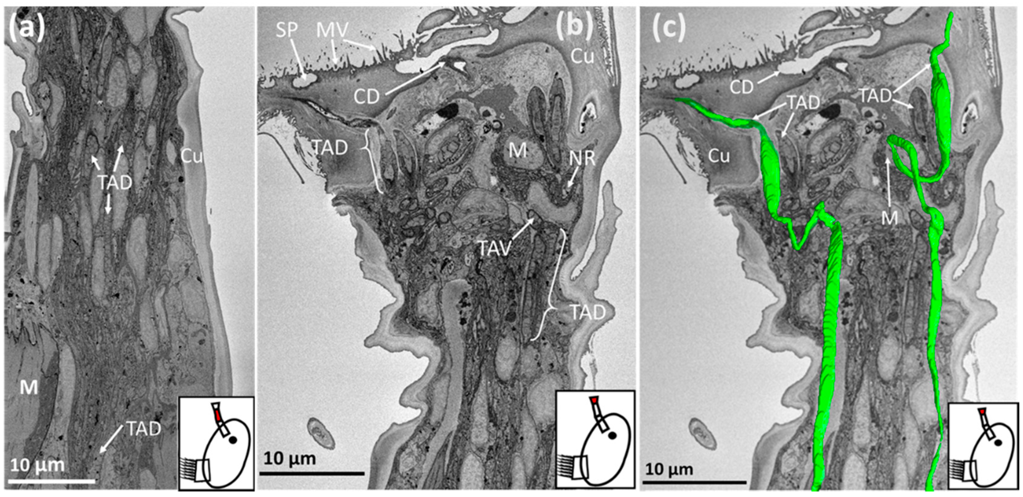
Figure 6.
SBF-SEM images of Megabalanus coccopoma: (a) = second antennular segment, (b) = third antennular segment., (c) = third antennular segment overlaid with a 3-D model of temporary adhesive ducts (green). The region where the image was captured is highlighted in red on the schematic inset. TAD = temporary adhesive duct, TAV = temporary adhesive vesicle, M = muscle, SP = secretory pore, MV = microvilli, CD = cement duct, Cu = cuticle, NR = neurone.

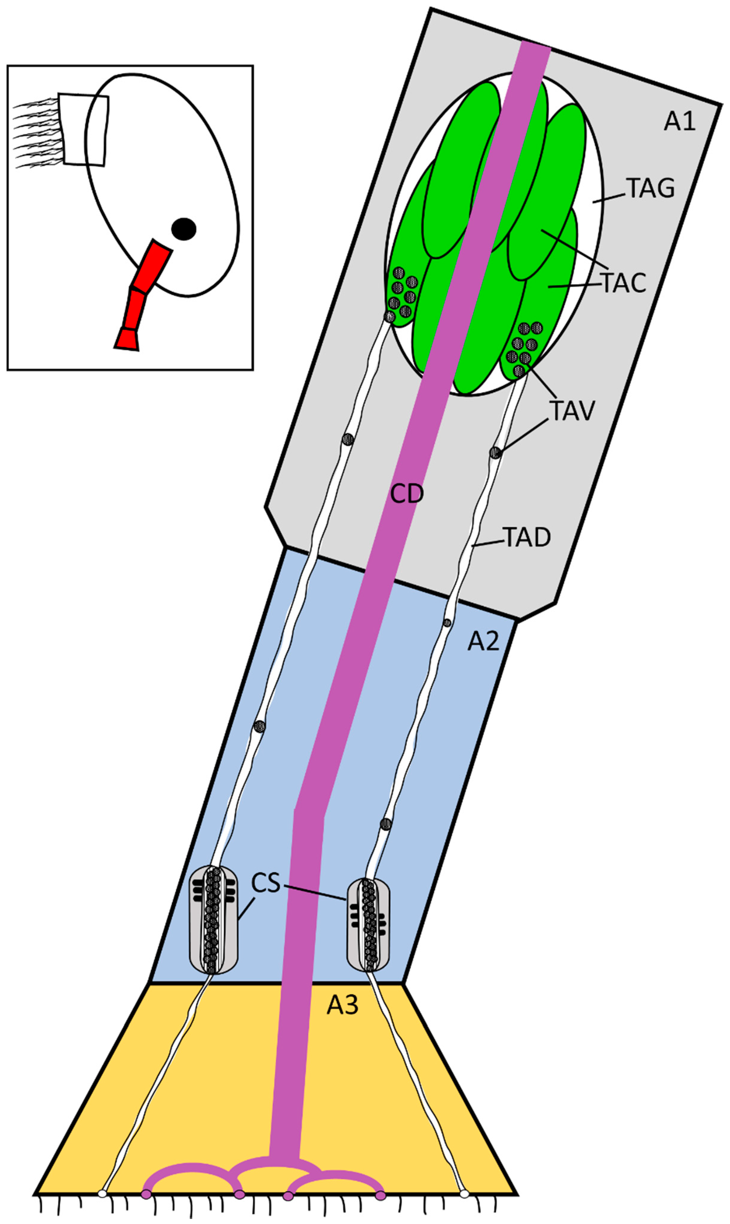
Figure 7.
Updated schematic diagram (Figure 1) of the temporary adhesive system, with the gland located in the proximal first antennular segment. Not to scale. The temporary adhesive gland contains numerous cells for the synthesis and packing of the temporary adhesive and each cell feeds one duct. The region detailed in the schematic is highlighted in red on the inset. A1 = first antennular segment, A2 = second antennular segment, A3 = third antennular segment (attachment disc), CD = cement duct, TAG = temporary adhesive gland, TAC = temporary adhesive gland cell, TAV = temporary adhesive vesicle, TAD = temporary adhesive duct, CS = putative collecting structures, previously proposed to be the temporary adhesive gland by Nott and Foster [11].


Table 1.
Details on the parameters selected for image capture using the Gatan 3view system. “Series” refers to the z-stack of images collected and compiled for three-dimensional model reconstruction, while “Stills” are the images collected for two-dimensional presentation.
Table 1.
Details on the parameters selected for image capture using the Gatan 3view system. “Series” refers to the z-stack of images collected and compiled for three-dimensional model reconstruction, while “Stills” are the images collected for two-dimensional presentation.
| Species | Magnification | Pixel Time | Section Thickness | Pixel Resolution |
|---|---|---|---|---|
| Balanus amphitrite | Series: 1290–1880× Stills: 898–4000× as required | Series: 20 µs Stills: 20 µs | Series: 100 nm Stills: 100 nm | Series: 20 nm, 2000 × 2000–3500 × 3500 Stills: 10 nm 4000 × 4000 |
| Megabalanus coccopoma | Series: 646× Stills: 157–6700× as required | Series: 20 µs Stills: 20 µs | Series: 100 nm Stills: 100 nm | Series: 25 nm, 3000 × 3000 Stills: 5.6 nm–478.5 nm, 2000 × 2000 |
Table 2.
Summary of the dimensions of the cyprid species imaged, and the key structures of their temporary adhesive systems (± standard deviation). TAV = temporary adhesive vesicle, TAD = temporary adhesive duct, TAG = temporary adhesive gland, A1 = first antennular segment, A2, second antennular segment, A3 = third antennular segment.
| Species | TAV Diameter | TAD Diameter | TAG Cells | TAG | Cyprid Length | A1 Length | A2 Length | A3 Diameter |
|---|---|---|---|---|---|---|---|---|
| Balanus amphitrite | ~250 nm (±89) | ~0.5 µm (±0.11) | ~4.5 × 4.5 × 10 µm | ~10 × 10 × 40 µm | ~400 µm | ~90 µm | ~80 µm | ~20 µm |
| Megabalanus coccopoma | ~400 nm (±104) | ~0.8 µm (±0.26) | ~5 × 5 × 25 µm | ~25 × 25 × 50 µm | ~500 µm | ~150 µm | ~140 µm | ~35 µm |
Publisher’s Note: MDPI stays neutral with regard to jurisdictional claims in published maps and institutional affiliations. |
© 2020 by the authors. Licensee MDPI, Basel, Switzerland. This article is an open access article distributed under the terms and conditions of the Creative Commons Attribution (CC BY) license (http://creativecommons.org/licenses/by/4.0/).
Share and Cite
MDPI and ACS Style
Raine, J.J.; Aldred, N.; Clare, A.S. Anatomy and Ultrastructure of the Cyprid Temporary Adhesive System in Two Species of Acorn Barnacle. J. Mar. Sci. Eng. 2020, 8, 968. https://doi.org/10.3390/jmse8120968
AMA Style
Raine JJ, Aldred N, Clare AS. Anatomy and Ultrastructure of the Cyprid Temporary Adhesive System in Two Species of Acorn Barnacle. Journal of Marine Science and Engineering. 2020; 8(12):968. https://doi.org/10.3390/jmse8120968
Chicago/Turabian StyleRaine, Joshua J., Nick Aldred, and Anthony S. Clare. 2020. "Anatomy and Ultrastructure of the Cyprid Temporary Adhesive System in Two Species of Acorn Barnacle" Journal of Marine Science and Engineering 8, no. 12: 968. https://doi.org/10.3390/jmse8120968
Note that from the first issue of 2016, this journal uses article numbers instead of page numbers. See further details here.