Categorization and Characterization of Time Domain CMOS Temperature Sensors


Division of Electronics and Electrical Engineering, Dongguk University, Seoul 04620, Korea
Sensors 2020, 20(22), 6700; https://doi.org/10.3390/s20226700
Submission received: 2 November 2020
/
Revised: 19 November 2020
/
Accepted: 22 November 2020
/
Published: 23 November 2020
(This article belongs to the Section Nanosensors)
Abstract
:Time domain complementary metal-oxide-semiconductor (CMOS) temperature sensors estimate the temperature of a sensory device by measuring the frequency, period and/or delay time instead of the voltage and/or current signals that have been traditionally measured for a long time. In this paper, the time domain CMOS temperature sensors are categorized into twelve types by using the temperature estimation function which is newly defined as the ratio of two measured time domain signals. The categorized time domain CMOS temperature sensors, which have been published in literature, show different characteristics respectively in terms of temperature conversion rate, die area, process variation compensation, temperature error, power supply voltage sensitivity and so on. Based on their characteristics, we can choose the most appropriate one from twelve types to satisfy a given specification.
1. Introduction
Temperature sensors have been widely used for thermal monitoring in various applications such as military, aerospace, scientific research, industry, agriculture, medicine, transportation and so on. Specifically, the thermal management of processors and memories, the ambient temperature monitoring for smart greenhouses, the human body temperature tracking for medical purposes and so on are the representative examples of temperature sensor applications.
The most popular temperature sensors used today are the thermocouple, resistive temperature device (RTD), thermistor and integrated silicon-based sensors. Among them, the last one is known to have the relatively narrow measurement range of −55 °C to 150 °C and the relatively low measurement accuracy of ±1 °C compared to the others. However, it is attractive in that it can be easily integrated on the same silicon with the target system, it is not expensive, and it has the relatively fast conversion rate [1].
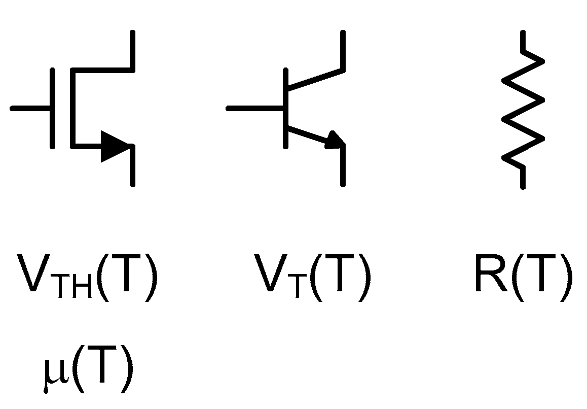
Temperature can be estimated by measuring the voltage and/or current signals of a sensory device of which certain characteristic varies depending on the temperature. For integrated circuits, sensory devices mean a complementary metal-oxide-semiconductor (CMOS) transistor, a bipolar junction transistor (BJT) transistor and a kind of passive resistor as shown in Figure 1. For example, a CMOS transistor has the threshold voltage, VTH(T), and the mobility, μ(T), which change depending on the temperature and a BJT transistor has the thermal voltage, VT(T), which also changes with the temperature. Passive resistors also have the temperature dependent resistance, R(T). So, we can measure the temperature indirectly through the voltage and/or current signals of a sensory device.
Measuring something is to represent it by using a ratio of two quantities. Length is represented by the ratio of the distance between two endpoints and the unit reference like 1 mm or 1 μm and weight is represented by the ratio of the mass and the unit reference like 1 g or 1 mg. However, since temperature cannot be directly measured by the integrated circuits, we should instead measure the temperature dependent voltage and/or current signals and represent it by using the ratio of the measured quantities [2,3,4,5,6,7,8,9,10,11,12,13,14,15,16,17]. This ratio is later converted to the temperature in the unit of °C or ºF.
As the CMOS process scales down and the supply voltage shrinks, the recent trend is to prefer the time domain signals such as the frequency, period and delay time to the voltage and current signals [18,19,20,21,22,23,24,25,26,27,28,29,30,31,32]. So, the time domain CMOS temperature sensors are holding more attraction than the traditional CMOS temperature sensors based on the voltage and/or current signals.
Therefore, this review paper discusses on the categorization and characterization of the time domain CMOS temperature sensors. In Section 2, the temperature estimation function is defined as the ratio of two measured time domain signals and by using the defined temperature estimation function it is shown that all the time domain CMOS temperature sensors can be categorized into twelve types. In Section 3, the temperature estimation functions of the previously published time domain CMOS temperature sensors in literature are derived and by using the derived temperature estimation functions it is shown that they have different characteristics respectively in terms of temperature conversion rate, die area, process variation compensation, temperature error, power supply voltage sensitivity and so on. Finally, the summary and discussion are given in Section 4 and the conclusion is given in Section 5.
2. Categorization
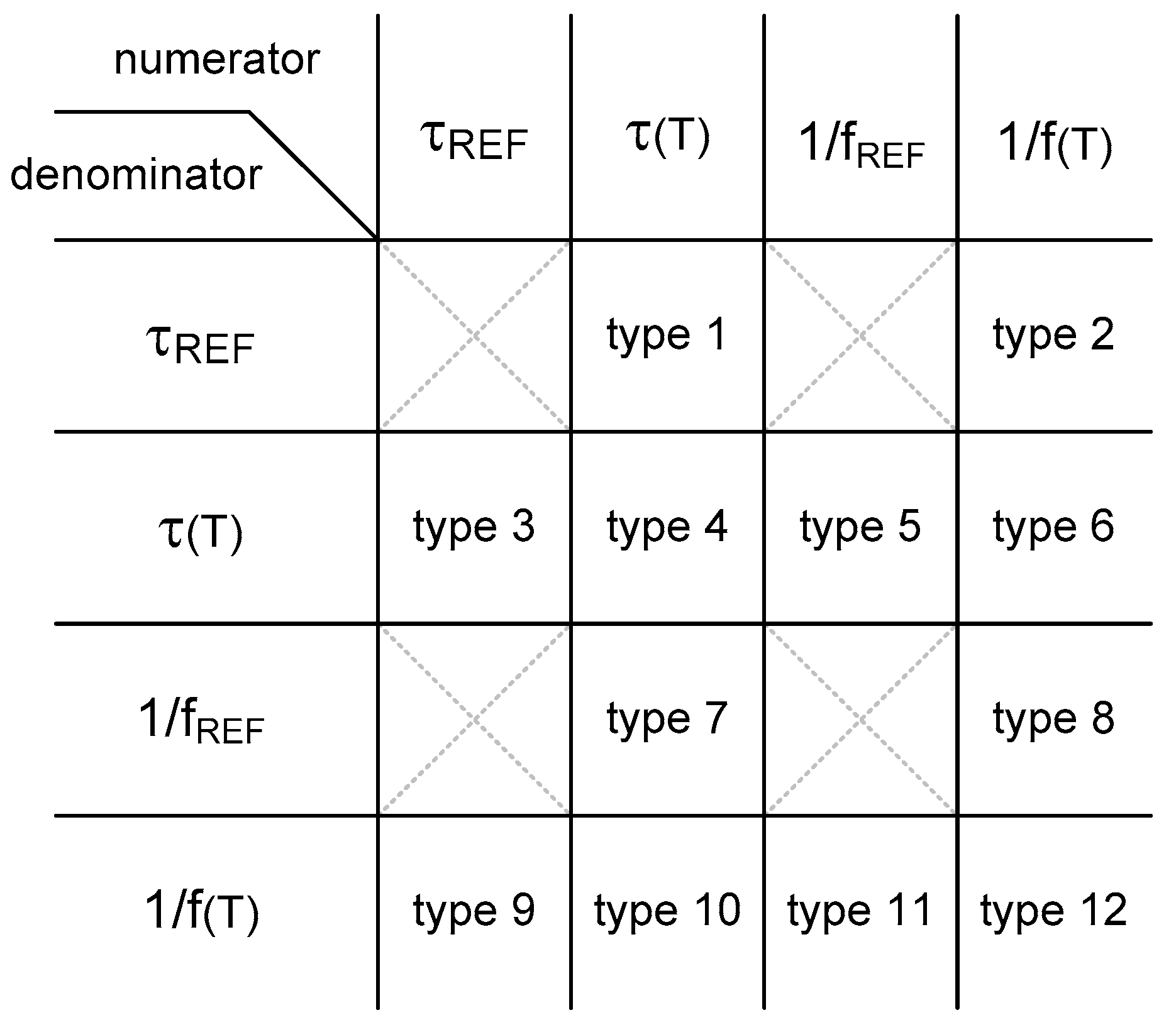
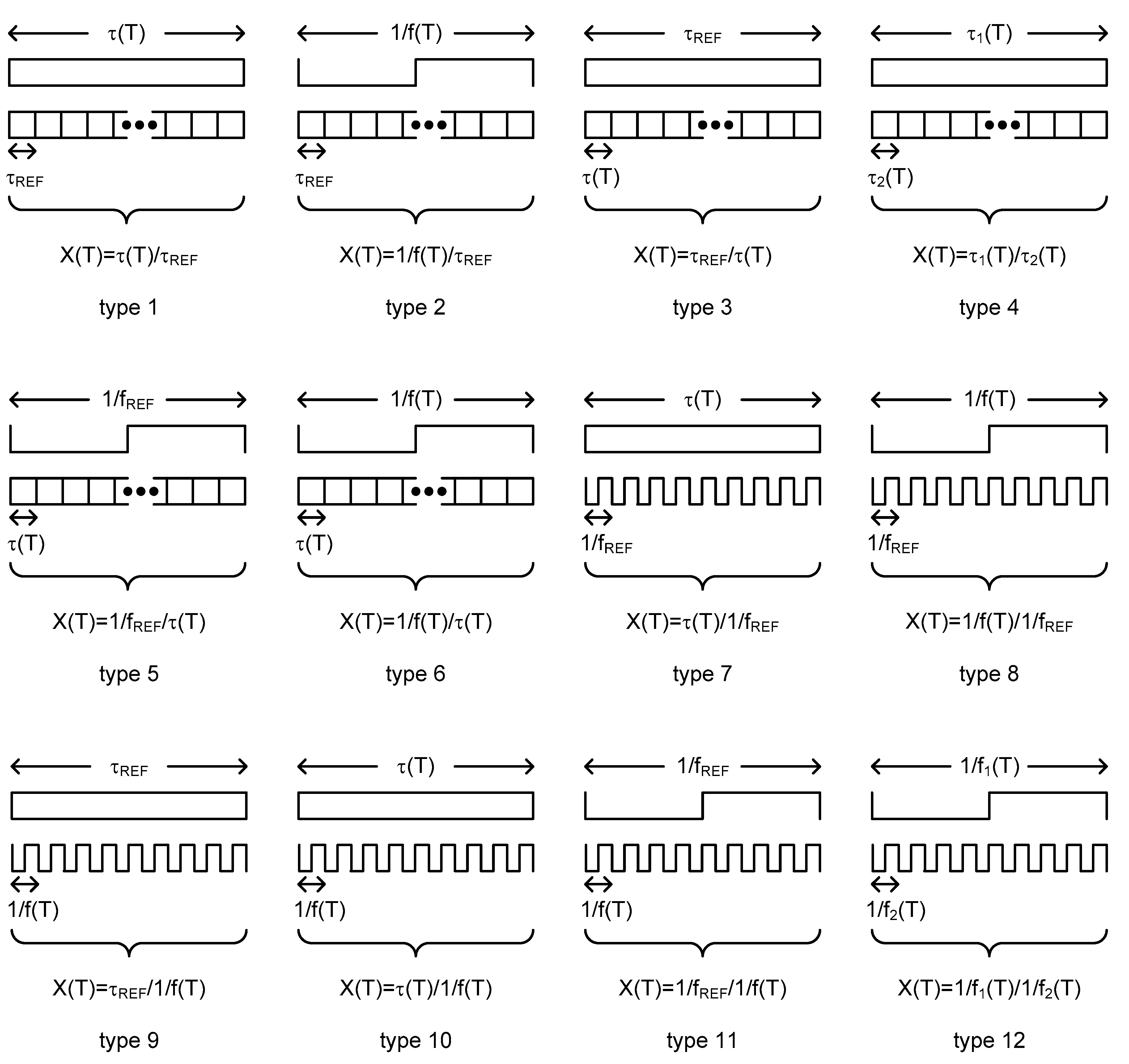
To categorize the time domain CMOS temperature sensors, I define the temperature estimation function as the ratio of two measured time domain signals in this paper. The time domain CMOS temperature sensors can be categorized on the basis of the types of the temperature estimation functions. The time domain signals, which are generally used in time domain CMOS temperature sensors, are the frequency, period and delay time. Among them, since the frequency is the reciprocal of the period, we can consider the period and the delay time as the representative time domain signals. The period is related to an oscillator or a clock signal applied externally and the delay time is related to a delay cell or a delay line. If we denote the temperature dependent period and the temperature independent period as 1/f(T) and 1/fREF, respectively, the temperature dependent delay time and the temperature independent delay time can also be denoted as τ(T) and τREF, respectively. Therefore, from these 4 kinds of time domain signals, we can obtain overall 16 types of temperature estimation functions as summarized in Figure 2. However, if we exclude the 4 types of temperature estimation functions which are not dependent of the temperature at all, there exist only 12 types of temperature estimation functions. I have named them one by one as type 1, type 2, …, type 12 and drawn their conceptual diagrams for intuitive understanding in Figure 3. Here, X(T) is the temperature estimation function.
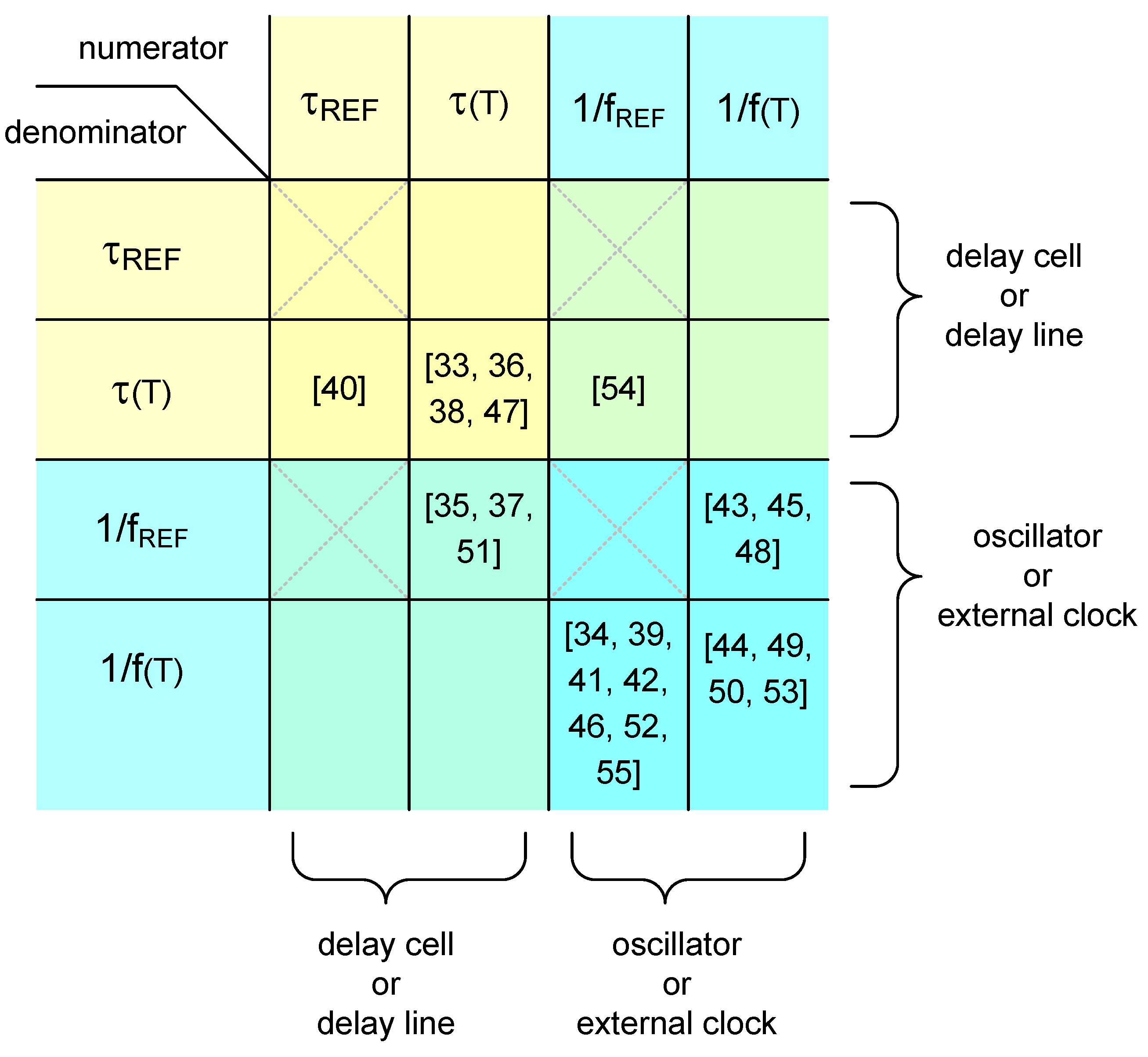
According to my survey, a few tens of papers on time domain CMOS temperature sensors have been published since 2005 [33,34,35,36,37,38,39,40,41,42,43,44,45,46,47,48,49,50,51,52,53,54,55]. They can all be categorized on the basis of their temperature estimation functions. As shown in Figure 4, there are the types which have been adopted preferably and the other types which have never been adopted until now. In the following section, the temperature estimation functions are derived for the previously published time domain CMOS temperature sensors which were categorized into each type. And, by using the derived temperature estimation function, it is shown that the time domain CMOS temperature sensors have different characteristics in terms of temperature conversion rate, die area, process variation compensation, temperature error, power supply voltage sensitivity and so on.
3. Characterization
The previously published time domain CMOS temperature sensors in literature [33,34,35,36,37,38,39,40,41,42,43,44,45,46,47,48,49,50,51,52,53,54,55] can be categorized into one of the types 3, 4, 5, 7, 8, 11 and 12, respectively, as shown in Figure 4. In this section, their temperature estimation functions, X(T), are derived first and then characterized as follows.
3.1. Type 3
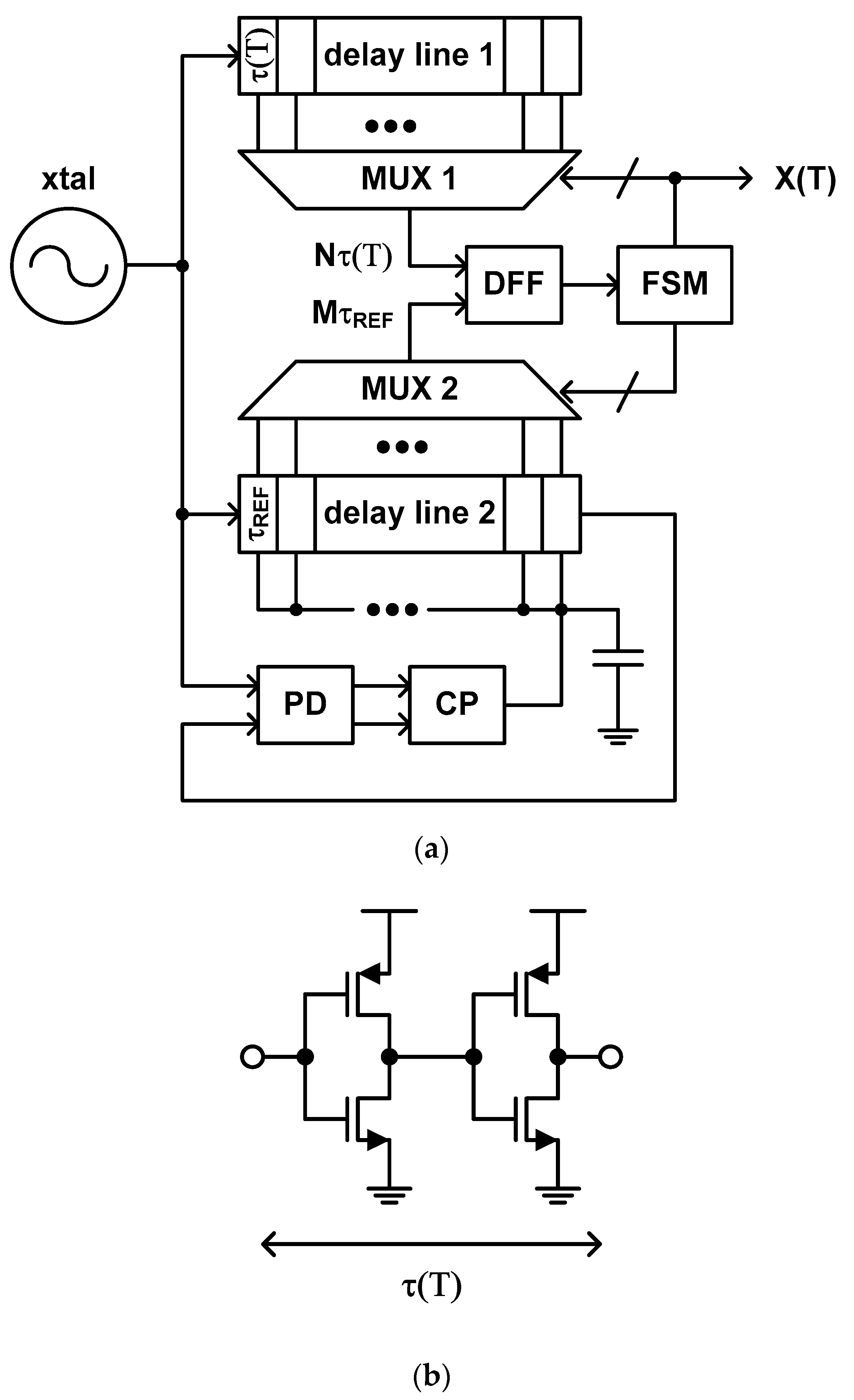
The temperature estimation function of this type of time domain CMOS temperature sensor is defined as the ratio of the temperature independent delay time and the temperature dependent delay time. As shown in Figure 5a, the temperature sensor, which was proposed by D. Ha et al. in 2012, has two delay lines, one of which generates the temperature dependent delay time and the other generates the temperature independent delay time by synchronizing its delay time to the clock period of a temperature stable crystal oscillator applied externally with the help of a delay locked loop (DLL) which consists of a phase detector (PD), a charge pump (CP) and a loop filter in addition to the second delay line [40].
Since a CMOS inverter is used as a delay cell of the delay line as shown in Figure 5b, the delay time of each delay cell may be expressed as
under the normal DC bias condition where W and L are the channel width and length, CL is the load capacitance, COX is the gate oxide capacitance per unit area and VDD is the power supply voltage [56,57]. From (1), the temperature estimation function can be obtained as
where M is a digital value determined during one-point calibration at a certain calibration temperature, TC, to let where NC is the predetermined reference digital value of the multiplexer (MUX) 1 pairing with TC. In this architecture, N is finally determined by the finite state machine (FSM) after the D flipflop (DFF) compares two clock signals from MUX1 and MUX2 and decides which one is faster than the other repeatedly.
To digitize the temperature estimation function, this temperature sensor utilizes many number of fine delay cells instead of a binary counter. Since this structure does not need to wait too long time for the binary counter to finish its counting operation, it can obtain high temperature resolution as well as fast conversation rate at the same time. However, it has to occupy large die area because many number of fine delay cells are required to achieve high temperature resolution. Moreover, the inevitable mismatches between the fine delay cells distributed over large die area cannot help but worsen the temperature error even if we pay careful attention to the layout. Consequently, this temperature sensor [40] shows the relatively fast conversion rate of 5 k samples/s, the relatively large temperature error of −4.0 °C to +4.0 °C over the temperature range from 0 °C to 100 °C, and the relatively large die area of 0.12 mm2.
If we go along with the authors that μ(T) is much more effective than VTH(T) in (1) so that the temperature estimation function of (2) is almost not affected by VTH(T), the Equation (2) can be approximated to (3) because μ(T) is generally represented as (4) with a negative fitting coefficient of α [40,58,59,60,61,62,63]. Thus, one-point calibration can be used for process variation compensation.
However, since (3) is still not a linear function but an exponential function with respect to T, this temperature sensor is in need of additional digital post processing block for nonlinear-to-linear mapping to minimize the temperature error. Lastly, as the temperature estimation function of (2) is a function of not only μ(T) and VTH(T) but also VDD, this temperature sensor is necessarily sensitive to the power supply variation. Thus, this temperature sensor should be implemented along with an additional integrated voltage regulator [64,65,66,67,68,69,70,71,72,73,74,75] for constant VDD. The measured VDD sensitivity is as large as 1.6 °C/mV with no voltage regulator.
3.2. Type 4
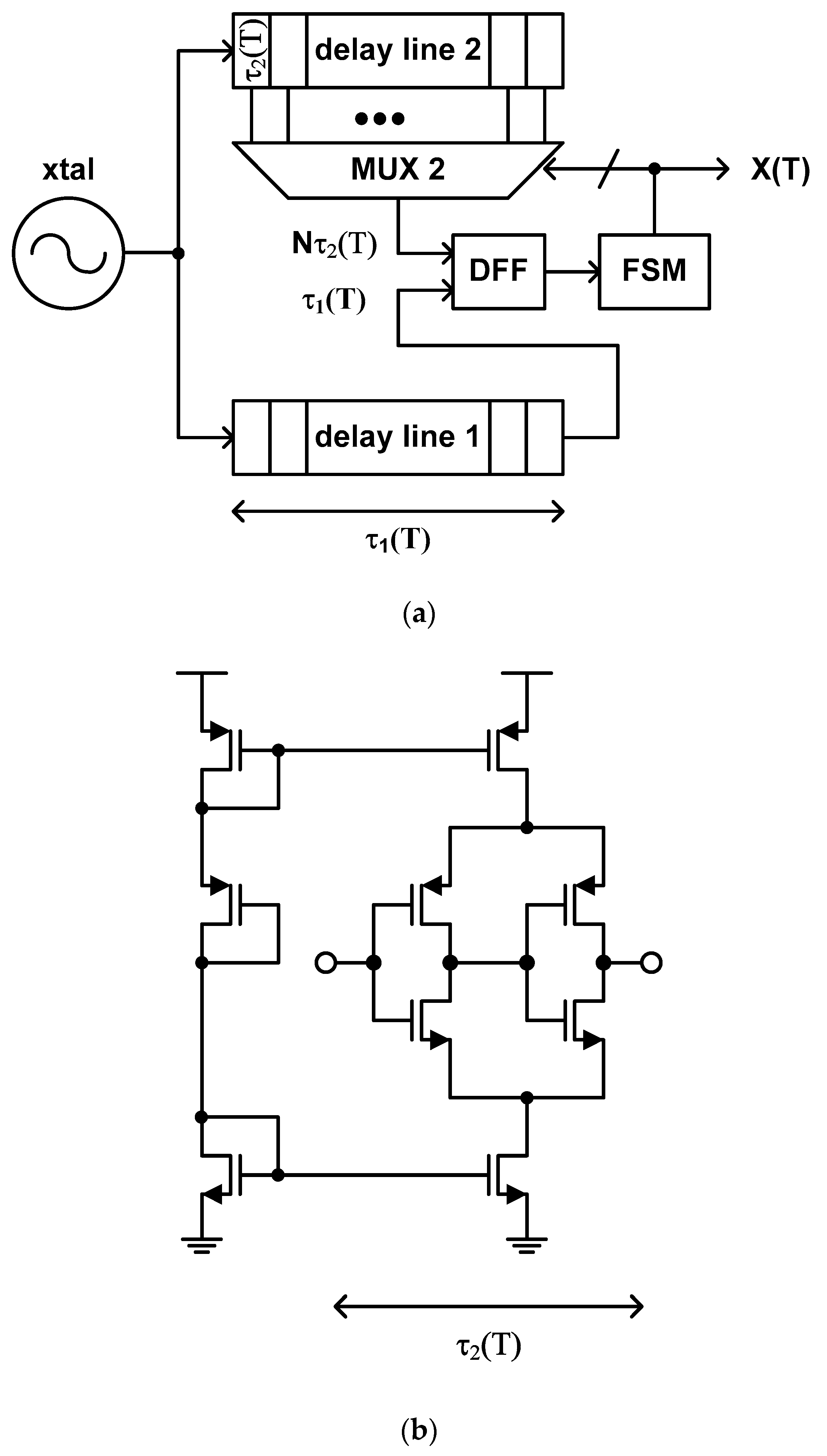
The temperature estimation function of this type of time domain CMOS temperature sensor is defined as the ratio of two different temperature dependent delay times. The typical structure of this type of temperature sensor, which was proposed by P. Chen et al. in 2010 [38], includes two delay lines, of which delay times vary in a different way from each other with respect to temperature, and a successive approximation register (SAR) control logic [76,77,78,79,80,81,82,83,84,85,86,87] implemented as an FSM. For example, if one of these delay lines is composed of the general inverter type delay cells of Figure 5b, then the other is composed of the delay cells shown in Figure 6b which are less sensitive to temperature [33,38].
Thus, the temperature estimation function can be represented as
where a and b are the coefficients. If we accept the authors’ assertion that the order of the delay time, τ2(T), of the delay cell of Figure 6b with respect to temperature can be made exactly 1 less than that of the delay time, τ1(T), of the delay cell of Figure 5b, the temperature estimation function of (5) may become a linear equation of T and the coefficient, b, will be 0 exactly. If this is true, it is very lucky and one-point calibration may be enough for process variation compensation because we just need to determine the value of a in (5). However, since the orders of τ1(T) and τ2(T) cannot be controlled accurately, the temperature estimation function actually becomes a bit different from the linear equation of T and the coefficient, b, also cannot be zero. Thus, we should necessarily carry out two-point calibration for process variation compensation for this type of temperature sensor. The second delay line of this temperature sensor mainly functions like the digital post processing block which was used for nonlinear-to-linear mapping to reduce the temperature error of the type 3 temperature sensor.
Like the type 3, this type of temperature sensor has also a large number of delay cells instead of a binary counter to obtain a fine temperature resolution. Thus, it has fast temperature conversion rate at the cost of large die area. Of course, since it does not require a DLL anymore, we can save a small portion of active die area compared to type 3. The mismatch problem between fine delay cells distributed over large die area still exists. In [38], the implemented time domain CMOS temperature sensor shows the temperature resolution of 0.1 °C, the temperature error of −0.4 °C to +0.6 °C over the temperature range from 0 °C to 90 °C, and the very large die area of 0.6 mm2. Because the delay time of the CMOS inverter delay cell is a function of VDD as shown in (1), this type of temperature sensor is also very sensitive to VDD variation.
3.3. Type 5
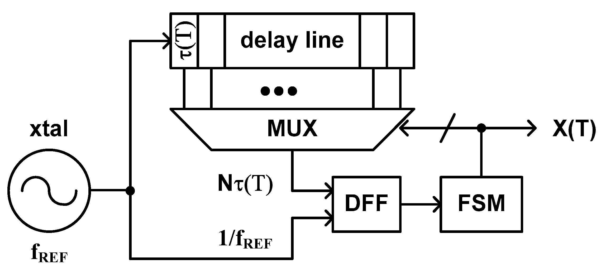
This type of time domain CMOS temperature sensor was proposed by Z. Xu et al. in 2020 [54]. The architecture of this temperature sensor consists of a delay line, of which delay time is dependent of temperature, and a SAR control logic as shown in Figure 7. The DFF and the SAR control logic determine the number of fine delay cells, which the clock signal coming from a crystal oscillator should go through within the delay line, to make the period of the clock signal, 1/fREF, be equal to the delay time of the selected delay line, N × τ(T). Thus, the temperature estimation function of this type of temperature sensor is represented as follows.
Compared to the previous type 3 and 4, this type of temperature sensor has the merit of requiring only one delay line inside. Although it still needs a large number of fine delay cells for high temperature resolution, it is true that one delay line occupies less die area than two delay lines do. This temperature sensor has fast conversion rate because it utilizes a SAR based delay line instead of a binary counter, but the temperature error is still vulnerable to the mismatch between fine delay cells distributed over large die area. The temperature error of this type of temperature sensor depends on how symmetrically and uniformly we can layout the fine delay cells and how accurately and carefully we can trim the layout of each fine delay cell through iterative post layout simulations. Additionally, since the temperature estimation function is inversely proportional to τ(T) as shown in (6), we can reduce the temperature error by adopting a specially designed delay cell which can linearize 1/τ(T) as much as possible. From (6), we can see that two-point calibration is necessary to determine the coefficients, a and b, of the temperature estimation function for process variation compensation.
The temperature sensor which was implemented in [54] shows the temperature error of −1.6 °C to +0.6 °C over the temperature range from 0 °C to 100 °C, the temperature resolution of 0.49 °C, and the relatively fast conversion rate of 25 ksamples/s. The active die area is as large as 0.432 mm2. Since the VDD sensitivity of this temperature sensor depends on the structure of the delay cell, if the inverter type delay cell of Figure 5b is used, the temperature sensor cannot help but has poor VDD sensitivity. Thus, we generally need an additional voltage regulator to keep VDD as constant as possible.
3.4. Type 7
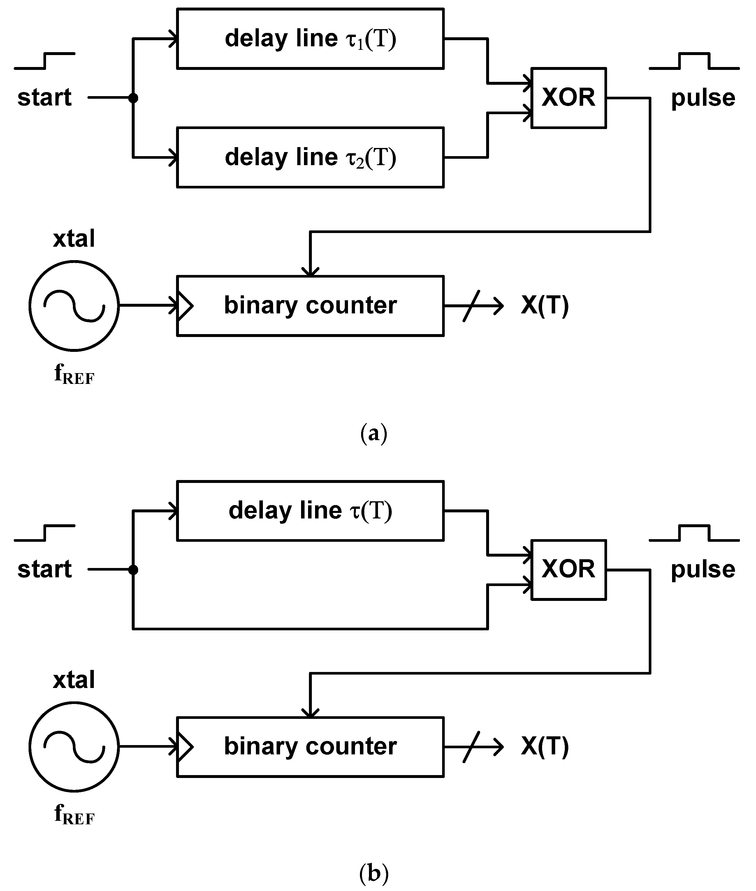
As M. K. Law et el. have proposed in 2009 and 2010, this type of time domain CMOS temperature sensor can be implemented by using two delay lines and a binary counter as shown in Figure 8a [35,37]. If two delay lines are designed to have different delay times with respect to temperature, i.e., one of which has a positive temperature coefficient and the other has a negative temperature coefficient, we can obtain a pulse signal of which pulse width equals to the difference of their delay times at the output node of the XOR gate. Then, the temperature estimation function of this type of temperature sensor is defined as the ratio of the difference between the delay times of two delay lines and the period of the temperature independent clock signal applied from an external crystal oscillator as follows.
If we decide to use only a single delay line to simplify the architecture, we can do it by applying the delayed start signal with the original start signal as the dual inputs of the XOR gate as shown in Figure 8b. Then, a pulse signal, of which pulse width equals to the delay time of the delay line, is generated at the output node of the XOR gate [51]. In this case, the temperature estimation function is defined as the ratio of the delay time of a single delay line and the period of the temperature independent clock signal applied from a crystal oscillator.
Since this type of temperature sensor utilizes a binary counter for digitizing the temperature modulated pulse width rather than the delay line which includes a large number of fine delay cells like type 3, 4 and 5, it has a merit of occupying relatively small die area and can have a fine temperature resolution at the cost of relatively slow conversion rate. Consequently, the temperature sensor implemented in [37] has the relatively small die area of 0.0416 mm2, the temperature resolution of 0.14 °C to 0.21 °C and the relatively slow conversion rate of 333 samples/s. Over the temperature range from −10 °C to +30 °C, it shows the temperature error of −0.8 °C to +1.0 °C.
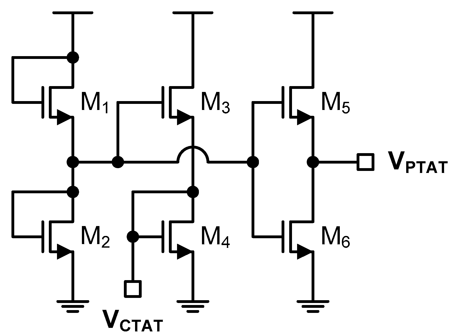
In Figure 8, the delay lines can be implemented in various ways. One of them is to use a proportional to the absolute temperature (PTAT) and a complementary to the absolute temperature (CTAT) signals [88,89,90,91,92,93,94]. If the PTAT and CTAT voltages are generated by the NMOS transistors operating in the subthreshold region as shown in Figure 9, the PTAT and CTAT voltages can be represented as follows.
where
and G(⋅) is the Lambert-W function [37]. If the PTAT and CTAT voltages are converted to the PTAT and CTAT currents like I1(T) = VPTAT(T)/R and I2(T) = VCTAT(T)/R and the delay times of the delay lines are determined as τ1(T) = C × VDD/2I1(T) and τ2(T) = C × VDD/2I2(T), respectively, as analyzed in [37], the temperature estimation function can be represented as follows.
Since we should determine the coefficients, a and b, of (12), for process variation compensation, two-point calibration should be carried out before temperature measurement. Lastly, if the temperature estimation function depends on VDD as shown in (12), the temperature sensor may have the huge temperature error due to VDD variation so that we need an additional voltage regulator to provide the constant supply voltage.
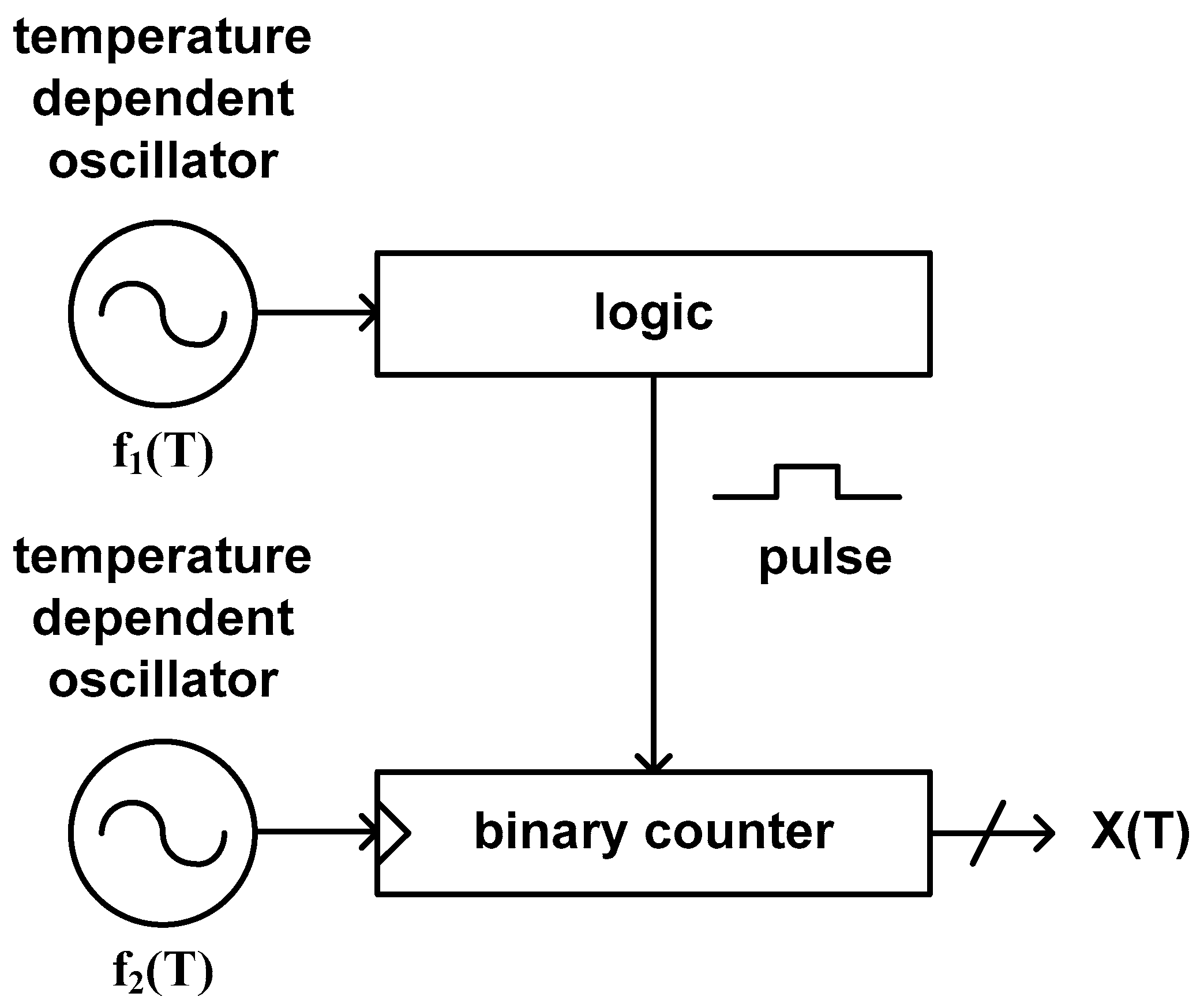
3.5. Type 8
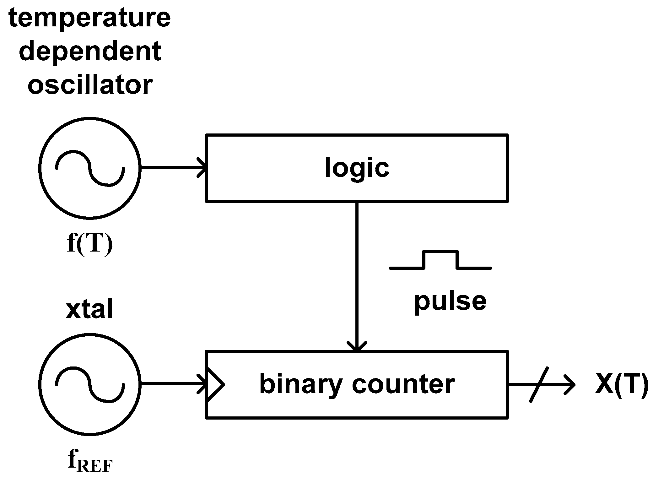
As shown in Figure 10, this type of time domain CMOS temperature sensor consists of a temperature dependent oscillator, a digital logic generating a pulse signal of which pulse width is proportional to the clock period of the temperature dependent oscillator and a binary counter. The digital logic can be implemented by using another binary counter [43], an XNOR gate with additional clock signal [45,48] or in other ways. This type of temperature sensor estimates the temperature by counting the number of the temperature independent clock period of a crystal oscillator during the pulse width which is linear with the clock period of the temperature dependent oscillator. Thus, the temperature estimation function is defined as the ratio of the clock period of the temperature dependent oscillator and the clock period of the temperature stable crystal oscillator.
Since this type of temperature sensor utilizes a simple digital logic instead of the delay lines of type 7 to generate the temperature modulated pulse width, it has a merit of occupying very small die area. At the same time, since it utilizes a binary counter to digitize the temperature modulated pulse width, it can achieve relatively fine temperature resolution at the price of relatively slow conversion rate. Therefore, this type of temperature sensor implemented in [43] occupies the relatively small die area of 0.07 mm2, the fine temperature resolution of 0.045 °C and the relatively slow conversion rate of 10 samples/s. Over the temperature range from −40 °C to +120 °C, it shows the temperature error of −1.2 °C to +0.2 °C.
If a CMOS inverter is used as a delay cell of the temperature dependent oscillator in this architecture, the delay time of the delay cell can be represented by (1) and the clock period of this oscillator will be also linear with the delay time of (1). Consequently, the temperature estimation function of (13) can be approximated to aT + b, so that we need to carry out two-point calibration for process variation compensation. Furthermore, because the delay time of (1) is dependent of VDD, the clock period of the temperature dependent oscillator which is composed of the CMOS inverter delay cells is also dependent of VDD. So we should add a voltage regulator to reduce the supply voltage variation in this case.
3.6. Type 11
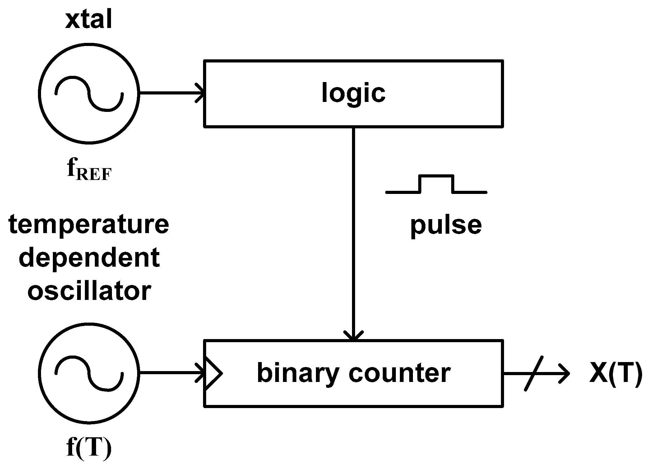
This type of time domain CMOS temperature sensor is based on an architecture similar to but a little bit different from type 8. It is because the temperature estimation function of this type is an inverse ratio of that of type 8 as can be seen in (14). Figure 11 shows the architecture of the time domain CMOS temperature sensor published by Y.-S. Lin et al. in 2008 [34]. This architecture was also used by S. Jeong et al. and Z. Tang et al. in 2014 [46] and 2020 [55], respectively. This temperature sensor estimates temperature by counting the number of clock signals generated from the temperature dependent oscillator during the pulse width which is proportional to the temperature independent reference clock period applied from a crystal oscillator.
Since this type of temperature sensor utilizes a digital logic, a binary counter and an integrated oscillator instead of a delay line to digitize the temperature estimation function, it can be implemented within a very small die area. However, as it counts the number of clock signals by using a binary counter, it should endure a low conversion rate to obtain a fine temperature resolution. In [46], the implemented temperature sensor occupies the relatively small die area of 0.09 mm2, the low conversion rate of 33 samples/s and the temperature resolution of 0.3 °C. Over the temperature range from 0 °C to 100 °C, it shows the temperature error of −1.4 °C to +1.5 °C. Specially, in this paper, for the purpose of obtaining VDD insensitive temperature characteristic, an NMOS transistor operating in the subthreshold region was used as a sensing element. Because the current equation of the NMOS transistor in the subthreshold region is almost independent of VDD, this temperature sensor shows the relatively small temperature error of −3.15 °C to +2.5 °C against the supply voltage variation from 1.0 V to 1.4 V.
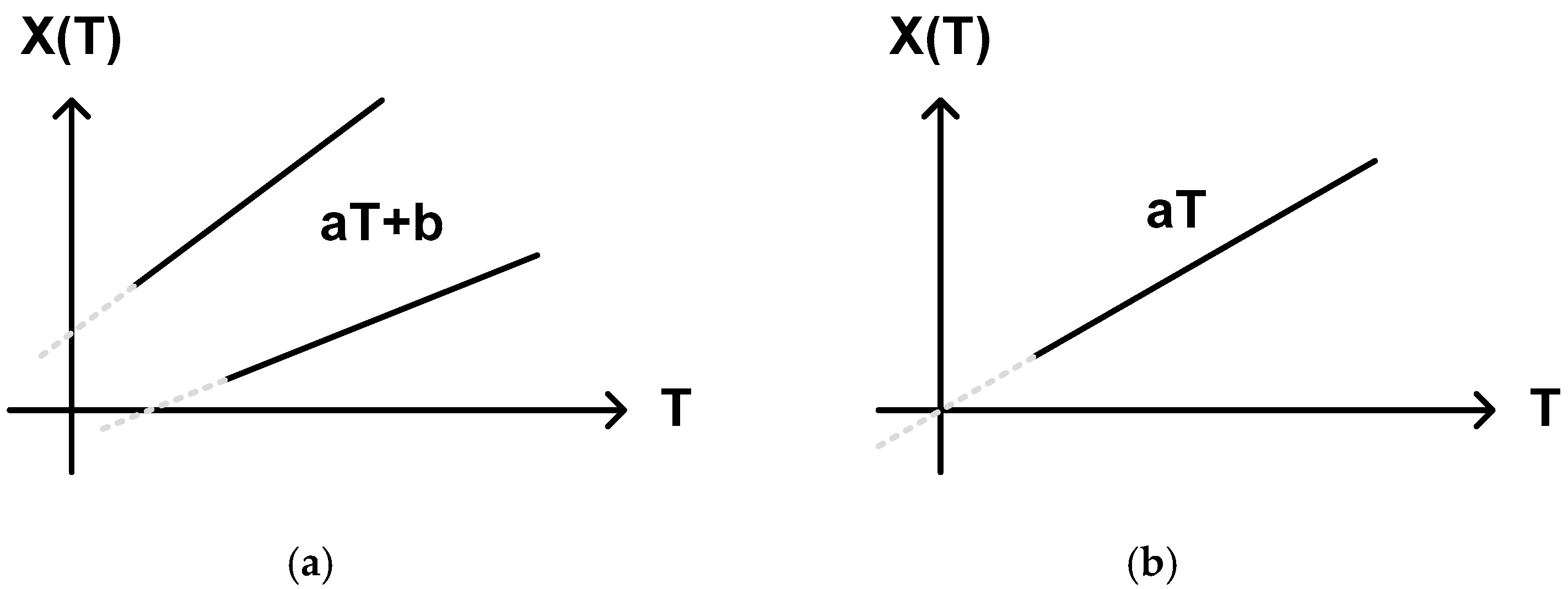
Whether we choose one-point calibration method or two-point calibration method for process variation compensation depends on the sensing element. As far as the sensing element has a good temperature linearity, the temperature estimation function can be represented by a linear function of the temperature. However, if the temperature characteristic of the adopted sensing element does not perfectly cross the zero point, the temperature estimation function may be approximated to a linear function with two coefficients like aT + b as shown in Figure 12a rather than a linear function with one coefficient like aT as shown in Figure 12b. In most of the cases, we should carry out two-point calibration to find out these coefficients, a and b.
3.7. Type 12
Contrary to the previously discussed type 8 and 11, this type of temperature sensor has the temperature estimation function defined as the ratio of two different clock periods of the integrated temperature dependent oscillators. Figure 13 shows the architecture of the type 12 time domain CMOS temperature sensor implemented in [50,53]. This temperature sensor estimates temperature by counting the number of clock signals generated from the second integrated temperature dependent oscillator during the pulse width which is proportional to the clock period of the first integrated temperature dependent oscillator.
This type of temperature sensor has a few advantages compared with the previous type 8 and 11 temperature sensors. First, an integrated oscillator consumes less power than a crystal oscillator and we can even further reduce the power consumption of the integrated oscillator by utilizing a sleep mode. Second, while an off-chip crystal oscillator is physically huge, an integrated oscillator occupies less die area. So, we can reduce the form factor of the temperature sensor. Third, if we use two integrated oscillators which have similar VDD sensitivities, this type of temperature sensor can be designed to be VDD insensitive by canceling out the effects of VDD variations from two integrated oscillators. Consequently, the implemented temperature sensor in [53] occupies the small die area of 0.074 mm2, the temperature resolution of 0.145 °C and the very low conversion rate of 1.2 samples/s. Over the temperature range from −20 °C to 80 °C, it shows the temperature error of −0.9 °C to 1.2 °C. At the same time, it has the VDD sensitivity of as low as 3.8 °C/V when the supply voltage varies from 0.7 V to 1.5 V. For process variation compensation, this temperature sensor requires two-point calibration.
3.8. Other Types
In addition to the types 3, 4, 5, 7, 8, 11 and 12, there are the other types 1, 2, 6, 9 and 10 which have not yet been published in literature until now as shown in Figure 4. The type 1 has the temperature estimation function defined as the ratio of a temperature dependent delay time and a temperature independent delay time and the type 2 has the temperature estimation function defined as the ratio of a temperature dependent period and a temperature independent delay time. Meanwhile, the type 6 temperature estimation function is defined as the ratio of a temperature dependent period and a temperature dependent delay time and the type 9 temperature estimation function is defined as the ratio of a temperature independent delay time and a temperature dependent period. Lastly, the type 10 temperature estimation function is defined as the ratio of a temperature dependent delay time and a temperature dependent period.
Since the temperature estimation function of the type 1 is the reciprocal of that of the type 3 as shown in Figure 4, these two types of temperature sensors can be implemented in the similar architecture. Also, since the temperature estimation functions of the type 2 and 9 are reciprocal to each other, these types of temperature sensors may commonly consist of a DLL based delay line for generating a temperature independent delay time and an integrated oscillator for generating a temperature dependent period. Similarly, since the temperature estimation functions of the types 6 and 10 are reciprocal to each other, they may commonly consist of a delay line for generating a temperature dependent delay time and an integrated oscillator for generating a temperature dependent period. That is, the temperature sensors of the types 2, 6, 9 and 10 require both of a delay line and an oscillator at the same time which considerably complicates the architecture of the time domain CMOS temperature sensor. It seems therefore these types of temperature sensors have not yet been published in literature. Of course, if we can find some ideas to reduce the design complexity of the architecture and some appropriate applications, these types of temperature sensors may be also implemented and utilized in the near future.
4. Discussion
Table 1 summarizes the performances of the time domain CMOS temperature sensors referred in this paper.
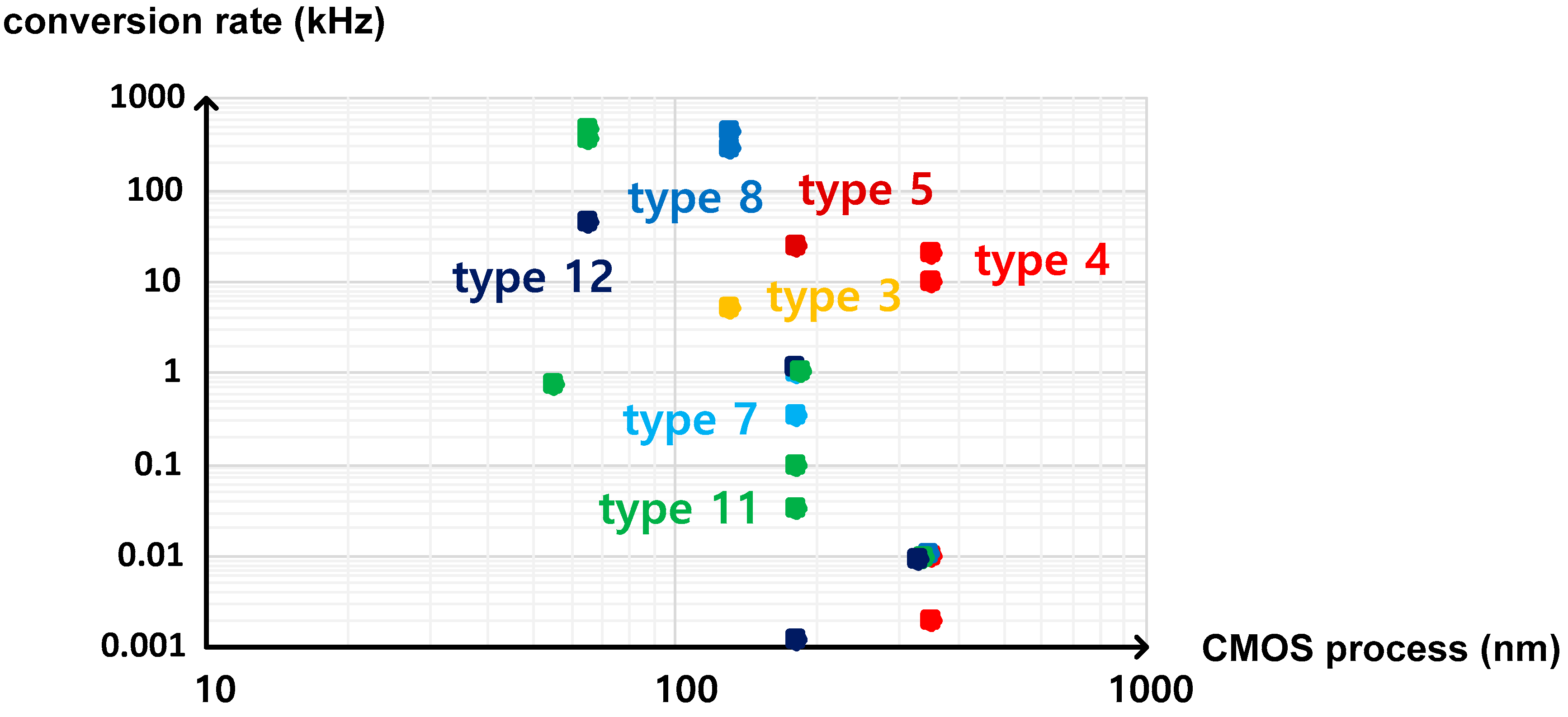
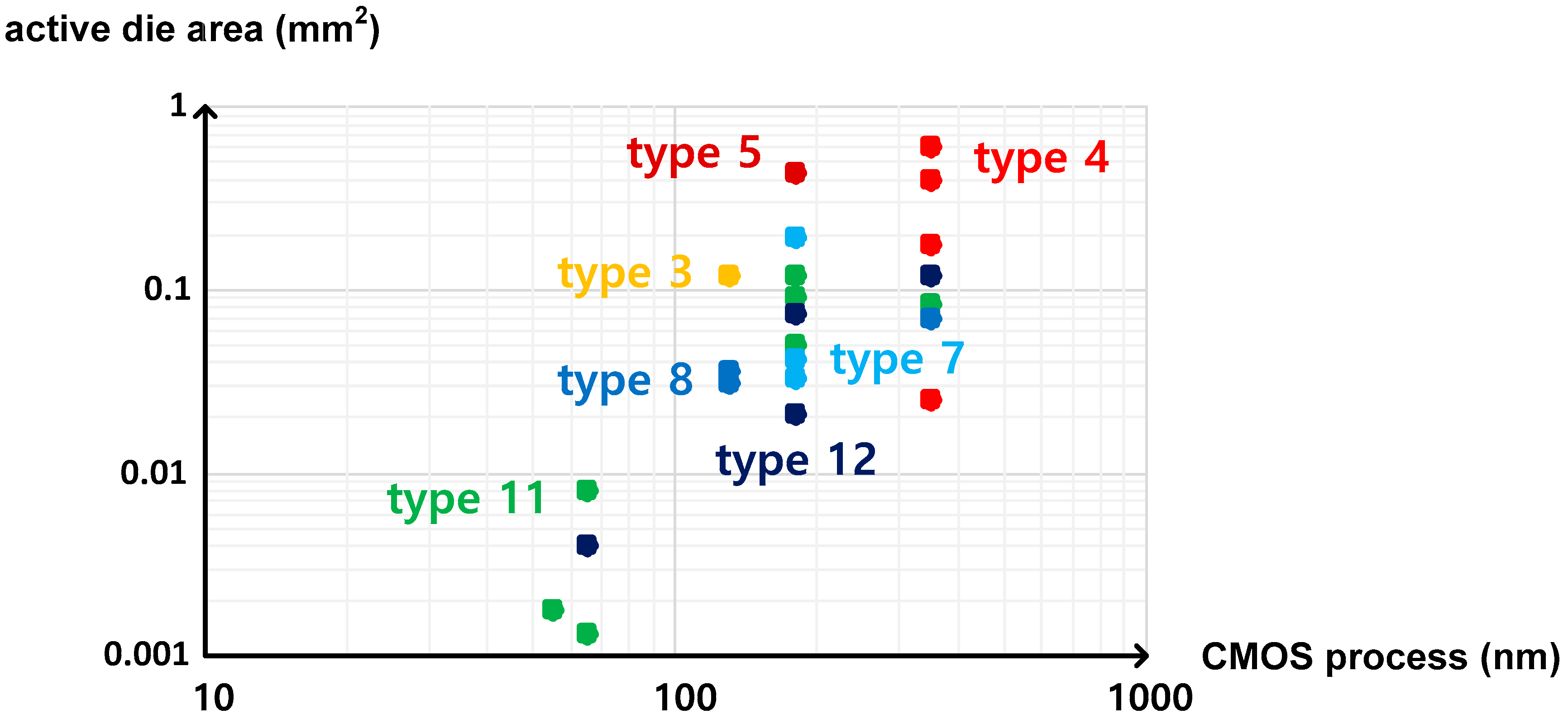
These temperature sensors, which were categorized into twelve types on the basis of the temperature estimation function in this paper, have the distinct characteristics as follows. First, if the temperature estimation function has τ(T) or τREF in the denominator, the temperature conversion rate is relatively fast, but the active die area is relatively large. Second, if the temperature estimation function has 1/f(T) or 1/fREF(T) in the denominator, the temperature conversion rate is relatively slow, but the active die area is relatively small. Figure 14 and Figure 15 show the temperature conversion rate and the active die area of the time domain CMOS temperature sensors summarized in Table 1 versus the CMOS process used for implementation. As shown in the figures, the temperature sensors of type 3, 4 and 5 have the faster temperature conversion rate and the larger die area than those of type 7, 8, 11 and 12 in general if they are implemented by using the CMOS processes with the same minimum channel length.
Additionally, if the temperature estimation function has 1/f(T) at least in one of the numerator and the denominator, the temperature sensor requires additional initialization time for an integrated oscillator to stabilize its oscillation frequency. Thus, the type 8, 11 and 12 temperature sensors are not adequate for the low power temperature monitoring systems if they turn on and off the system power for energy efficiency and do not provide enough time for the initialization of the integrated oscillator. In that case, the oscillator should be turned on all times whether it is used or not.
Finally, as the temperature estimation function is approximated to aT + b in most of the cases, the process variation compensation should be done by two-point calibration. Especially only when the temperature estimation function is approximated to aT with b = 0, one-point calibration can be used. The temperature error is directly related to the temperature characteristic of a sensing element and the temperature estimation function of a temperature sensor. If the temperature estimation function has τ(T) or τREF in the denominator, the temperature error arising from the mismatch between a large number of fine delay cells distributed over large die area may be added. The supply voltage sensitivity tends to become large if a CMOS inverter type delay cell is used in the delay line or the oscillator. For obtaining low VDD sensitivity, we can put τ(T) and/or 1/f(T) with almost same VDD sensitivities in the numerator and the denominator of the temperature estimation function like type 4 and 12 temperature sensors to cancel out the effects of VDD variations. Or, we can also make the temperature sensor less sensitive to VDD variation by adopting a CMOS transistor operating in the subthreshold region because the subthreshold current of the CMOS transistor is independent of VDD. Otherwise, we should always implement a voltage regulator additionally to suppress VDD variations in the temperature monitoring systems.
5. Conclusions
In this review paper, the time domain CMOS temperature sensors have been categorized into twelve types on the basis of their temperature estimation functions. The temperature estimation function is defined as the ratio of two measured time domain signals which are selected from a temperature independent delay time, a temperature dependent delay time, a temperature independent period and a temperature dependent period. The categorized temperature sensors have been discussed in terms of temperature conversion rate, die area, process variation compensation, temperature error, power supply voltage sensitivity and so on. Based on their characteristics, we can choose the most appropriate one from twelve types to satisfy a given specification.
Funding
This research was supported by Basic Science Research Program through the National Research Foundation of Korea (NRF) funded by the Ministry of Education (NRF-2017R1D1A1B03028325).
Acknowledgments
The author would like to thank IC Design Education Center (IDEC), Daejeon, South Korea, for supporting EDA tools.
Conflicts of Interest
The author declares no conflict of interest.
References
- Microchip Technology Inc. Temperature Sensing Technologies. AN679. 1998. Available online: http://ww1.microchip.com/downloads/en/Appnotes/00679a.pdf (accessed on 23 November 2020).
- Pu, X.; Ash, M.; Nagaraj, K.; Park, J.; Vu, S.; Kimelman, P.; Haye, S.D.L. An embedded 65nm CMOS remote temperature sensor with digital beta correction and series resistance cancellation achieving an inaccuracy of 0.4 °C (3σ) from −40 °C to 130 °C. IEEE J. Solid-State Circuits 2015, 50, 2127–2137. [Google Scholar] [CrossRef]
- Oshita, T.; Shor, J.; Duarte, D.E.; Kornfeld, A.; Zilberman, D. Compact BJT-based thermal sensor for processor applications in a 14 nm tri-gate CMOS process. IEEE J. Solid-State Circuits 2015, 50, 799–807. [Google Scholar] [CrossRef]
- Park, H.; Kim, J. A 0.8-V resistor-based temperature sensor in 65-nm CMOS with supply sensitivity of 0.28 °C/V. IEEE J. Solid-State Circuits 2018, 53, 906–912. [Google Scholar] [CrossRef]
- Weng, C.-H.; Wu, C.-K.; Lin, T.-H. A CMOS thermistor-embedded continuous-time delta-sigma temperature sensor with a resolution FoM of 0.65 pJ °C2. IEEE J. Solid-State Circuits 2015, 50, 2491–2500. [Google Scholar] [CrossRef]
- Wu, C.-K.; Chan, W.-S.; Lin, T.-H. A 80 kS/s 36 µW resistor-based temperature sensor using BGR-free SAR ADC with a unevenly-weighted resistor string in 0.18 µm CMOS. In Digest of Technical Papers of the 2011 Symposium on VLSI Circuits; IEEE: Piscataway, NJ, USA, 2011; pp. 222–223. [Google Scholar]
- Yousefzadeh, B.; Shalmany, S.H.; Makinwa, K.A.A. A BJT-based temperature-to-digital converter with ±60 mK (3σ) inaccuracy from −55 °C to +125 °C in 0.16-µm CMOS. IEEE J. Solid-State Circuits 2017, 52, 1044–1052. [Google Scholar] [CrossRef]
- Xu, K.; Huang, L.; Zhang, Z.; Zhao, J.; Zhang, Z.; Snyman, L.W.; Swart, J.W. Light emission from a poly-silicon device with carrier injection engineering. Mater. Sci. Eng. B 2018, 231, 28–31. [Google Scholar] [CrossRef]
- Sebastiano, F.; Breems, L.J.; Makinwa, K.A.A.; Drago, S.; Leenaerts, D.M.W.; Nauta, B. A 1.2-V 10-µW NPN-based temperature sensor in 65-nm CMOS with an inaccuracy of 0.2 °C (3σ) from −70 °C to 125 °C. IEEE J. Solid-State Circuits 2010, 45, 2591–2601. [Google Scholar] [CrossRef] [Green Version]
- Lakdawala, H.; Li, Y.W.; Raychowdhury, A.; Taylor, G.; Soumyanath, K. A 1.05 V 1.6 mW, 0.45 °C 3σ resolution ∑Δ based temperature sensor with parasitic resistance compensation in 32nm digital CMOS process. IEEE J. Solid-State Circuits 2009, 44, 3621–3630. [Google Scholar] [CrossRef]
- Pertijs, M.A.P.; Niederkorn, A.; Ma, X.; McKillop, B.; Bakker, A.; Huijsing, J.H. A CMOS smart temperature sensor with a 3σ inaccuracy of ±0.5 °C from −50 °C to 120 °C. IEEE J. Solid-State Circuits 2005, 40, 454–461. [Google Scholar] [CrossRef]
- Quay, R.; Moglestue, C.; Palankovski, V.; Selberherr, S. A temperature dependent model for the saturation velocity in semiconductor materials. Mater. Sci. Semicond. Proc. 2000, 3, 149–155. [Google Scholar] [CrossRef]
- Pertjis, M.A.P.; Makinwa, K.A.A.; Huijsing, A. A CMOS smart temperature sensor with a 3σ inaccuracy of ±0.1 °C from −55 °C to 125 °C. IEEE J. Solid-State Circuits 2005, 40, 2805–2815. [Google Scholar]
- Souri, K.; Chae, Y.; Makinwa, K.A.A. A CMOS temperature sensor with a voltage-calibrated inaccuracy of ±0.15 °C (3σ) from −55 °C to 125 °C. IEEE J. Solid-State Circuits 2013, 48, 292–301. [Google Scholar] [CrossRef] [Green Version]
- Tuthill, M. A switched-current switched-capacitor temperature sensor in 0.6-µm CMOS. IEEE J. Solid-State Circuits 1998, 33, 1117–1122. [Google Scholar] [CrossRef]
- Souri, K.; Makinwa, K.A.A. A 0.12 mm2 7.4 µW micropower temperature sensor with an inaccuracy of ±0.2 °C (3σ) from −30 °C to 125 °C. IEEE J. Solid-State Circuits 2011, 46, 1693–1700. [Google Scholar] [CrossRef]
- Xie, S.; Theuwissen, J.P. On-chip smart temperature sensors for dark current compensation in CMOS image sensors. IEEE Sens. J. 2019, 19, 7849–7860. [Google Scholar] [CrossRef]
- Li, J.; Pan, J.; Zhang, Y. Automatic calibration method of channel mismatches for wideband TI-ADC system. Electronics 2019, 8, 56. [Google Scholar] [CrossRef] [Green Version]
- Zhang, M.; Wang, H.; Qin, H.; Zhao, W.; Liu, Y. Phase difference measurement method based on progressive phase shift. Electronics 2018, 7, 86. [Google Scholar] [CrossRef] [Green Version]
- Fordymacka, A.; O’Connell, I. A 0.01-mm2 0.83-V input range SAR-based bridge-to-digital converter. IEEE Solid-State Circuits Lett. 2020, 3, 330–333. [Google Scholar] [CrossRef]
- Buhr, S.; Xu, X.; Kreibig, M.; Matthus, C.D.; Ellinger, F. Low power analogue equalizer with adaptive digital tuning for fast ethernet. IET Circuits Devices Syst. 2020, 5, 600–610. [Google Scholar] [CrossRef]
- Kim, J.; Kim, Y.-H.; Kim, K.; Yu, W.; Cho, S. A hybrid-domain two-step time-to-digital converter using a switch-based time-to-voltage converter and SAR ADC. IEEE Trans. Circuits Syst. II 2015, 62, 631–635. [Google Scholar] [CrossRef]
- Perrott, M.H.; Salvia, J.C.; Lee, F.S.; Partridge, A.; Mukherjee, S.; Arft, C.; Kim, J.; Arumugam, N.; Gupta, P.; Tabatabaei, S.; et al. A temperature-to-digital converter for a MEMS-based programmable oscillator with <±0.5-ppm frequency stability and <1-ps integrated jitter. IEEE J. Solid-State Circuits 2013, 48, 276–291. [Google Scholar]
- Pan, S.; Luo, Y.; Shalmany, S.H.; Makinwa, K.A.A. A resistor-based temperature sensor with a 0.13 pJ·K2 resolution FoM. IEEE J. Solid-State Circuits 2018, 53, 164–173. [Google Scholar] [CrossRef] [Green Version]
- Choi, W.; Lee, Y.; Kim, S.; Lee, S.; Jang, J.; Chun, J.; Makinwa, K.A.A.; Chae, Y. A compact resistor-based CMOS temperature sensor with an inaccuracy of 0.12 °C (3σ) and a resolution FoM of 0.43 pJ·K2 in 65-nm CMOS. IEEE J. Solid-State Circuits 2018, 53, 3356–3367. [Google Scholar] [CrossRef]
- Tang, X.; Pun, K.-P.; Ng, W.-T. A 0.9 V 5 kS/s resistor-based time-domain temperature sensor in 90nm CMOS with calibrated inaccuracy of −0.6 °C/0.8 °C from −40 °C to 125 °C. In Proceedings of the 2013 IEEE Asian Solid-State Circuits Conference, Singapore, 11–13 November 2013; pp. 169–172. [Google Scholar]
- Park, S.; Byun, S. A 0.026 mm2 time domain CMOS temperature sensor with simple current source. Micromachines 2020, 11, 899. [Google Scholar] [CrossRef]
- Angevare, J.; Pedala, L.; Sonmez, U.; Sebastiano, F.; Makinwa, K.A.A. A 2800-µm2 thermal-diffusivity temperature sensor with VCO-based readout in 160-nm CMOS. In Proceedings of the 2015 IEEE Asian Solid-State Circuits Conference, Xiamen, China, 9–11 November 2015; pp. 12–14. [Google Scholar]
- Shor, J.S.; Luria, K. Miniaturized BJT-based thermal sensor for microprocessors in 32-nm and 22-nm technologies. IEEE J. Solid-State Circuits 2013, 48, 2860–2867. [Google Scholar] [CrossRef]
- Islam, A.K.M.M.; Shiomi, J.; Ishihara, T.; Onodera, H. Wide-supply-range all-digital leakage variation sensor for on-chip process and temperature monitoring. IEEE J. Solid-State Circuits 2015, 50, 2475–2490. [Google Scholar] [CrossRef] [Green Version]
- Ituero, P.; Lopez-Vallejo, M.; Lopez-Barrio, C. A 0.0016 mm2 0.64nJ leakage-based CMOS temperature sensor. Sensors 2013, 13, 12648–12662. [Google Scholar] [CrossRef] [Green Version]
- Tang, Z.; Tan, N.N.; Shi, Z.; Yu, X.-P. A 1.2 V self-referenced temperature sensor with a time-domain readout and a two-step improvement on output dynamic range. IEEE Sens. J. 2018, 18, 1849–1858. [Google Scholar] [CrossRef]
- Chen, P.; Chen, C.-C.; Tsai, C.-C.; Lu, W.-F. A time-to-digital-converter-based CMOS smart temperature sensor. IEEE J. Solid-State Circuits 2005, 40, 1642–1648. [Google Scholar] [CrossRef]
- Lin, Y.-S.; Sylvester, D.; Blaauw, D. An ultra low power 1 V, 220 nW temperature sensor for passive wireless applications. In Proceedings of the 2008 IEEE Custom Integrated Circuits Conference, San Jose, CA, USA, 21–24 September 2008; pp. 507–510. [Google Scholar]
- Law, M.-K.; Bermak, A. A 405-nW CMOS Temperature Sensor Based on Linear MOS Operation. IEEE Trans. Circuits Syst. II Express Briefs 2009, 56, 891–895. [Google Scholar] [CrossRef] [Green Version]
- Chen, P.; Chen, T.-K.; Wang, Y.-S.; Chen, C.-C. A time-domain sub-micro watt temperature sensor with digital set-point programming. IEEE Sens. J. 2009, 9, 1639–1646. [Google Scholar] [CrossRef]
- Law, M.-K.; Bermak, A.; Luong, H.C. A sub-µW embedded CMOS temperature sensor for RFID food monitoring application. IEEE J. Solid-State Circuits 2010, 45, 1246–1255. [Google Scholar] [CrossRef]
- Chen, P.; Chen, C.-C.; Peng, Y.-H.; Wang, K.-M.; Wang, Y.-S. A time-domain SAR smart temperature sensor with curvature compensation and a 3σ inaccuracy of −0.4 °C~+0.6 °C over a 0 °C to 90 °C range. IEEE J. Solid-State Circuits 2010, 45, 600–609. [Google Scholar] [CrossRef]
- Vaz, A.; Ubarretxena, A.; Zalbide, I.; Pardo, D.; Solar, H.; Garcia-Alonso, A.; Berenguer, R. Full Passive UHF Tag With a Temperature Sensor Suitable for Human Body Temperature Monitoring. IEEE Trans. Circuits Syst. II Express Briefs 2010, 57, 95–99. [Google Scholar] [CrossRef]
- Ha, D.; Woo, K.; Meninger, S.; Xanthopoulos, T.; Crain, E.; Ham, N. Time-Domain CMOS Temperature Sensors With Dual Delay-Locked Loops for Microprocessor Thermal Monitoring. IEEE Trans. Large Scale Integr. (VLSI) Syst. 2011, 20, 1590–1601. [Google Scholar] [CrossRef]
- Hwang, S.; Koo, J.; Kim, K.; Lee, H.; Kim, C. A 0.008 mm2 500 μW 469kS/s frequency-to-digital converter based CMOS temperature sensor with process variation compensation. IEEE Trans. Circuits Syst. 2013, 60, 2241–2248. [Google Scholar] [CrossRef]
- Kim, K.; Lee, H.; Kim, C. 366-kS/s 1.09-nJ 0.0013-mm2 frequency-to-digital converter based CMOS temperature sensor utilizing multiphase clock. IEEE Trans. Large Scale Integr. (VLSI) Syst. 2013, 21, 1950–1954. [Google Scholar] [CrossRef]
- Chen, C.-C.; Chen, H.-W. A linearization time-domain CMOS smart temperature sensor using a curvature compensation oscillator. Sensors 2013, 13, 11439–11452. [Google Scholar] [CrossRef]
- Chen, C.-C.; Lin, S.-H. A time-domain CMOS oscillator-based thermostat with digital set-point programming. Sensors 2013, 13, 1679–1691. [Google Scholar] [CrossRef]
- An, Y.-J.; Ryu, K.; Jung, D.-H.; Woo, S.-H.; Jung, S.-O. An energy efficient time-domain temperature sensor for low-power on-chip thermal management. IEEE Sens. J. 2014, 14, 104–110. [Google Scholar] [CrossRef]
- Jeong, S.; Foo, Z.; Lee, Y.; Sim, J.-Y.; Blaauw, D.; Sylvester, D. A Fully-Integrated 71 nW CMOS Temperature Sensor for Low Power Wireless Sensor Nodes. IEEE J. Solid-State Circuits 2014, 49, 1682–1693. [Google Scholar] [CrossRef]
- Chen, C.-C.; Chen, H.-W. A low-cost CMOS smart temperature sensor using a thermal-sensing and pulse-shrinking delay line. IEEE Sens. J. 2014, 14, 278–284. [Google Scholar] [CrossRef]
- An, Y.-J.; Jung, D.-H.; Ryu, K.; Woo, S.-H.; Jung, S.-O. An energy-efficient all-digital time-domain-based CMOS temperature sensor for SoC thermal management. IEEE Trans. Large Scale Integr. (VLSI) Syst. 2015, 23, 1508–1517. [Google Scholar] [CrossRef]
- Deng, F.; He, Y.; Li, B.; Zhang, L.; Wu, X.; Fu, Z.; Zuo, L. Design of an embedded CMOS temperature sensor for passive RFIC tag chips. Sensors 2015, 15, 11442–11453. [Google Scholar] [CrossRef] [PubMed]
- Anand, T.; Makinwa, K.A.A.; Hanumolu, P.K. A VCO Based Highly Digital Temperature Sensor With 0.034 °C/mV Supply Sensitivity. IEEE J. Solid-State Circuits 2016, 51, 2651–2663. [Google Scholar] [CrossRef]
- Tran, T.-H.; Peng, H.-W.; Chao, P.C.-P.; Hsieh, J.-W. A log-ppm digitally controlled crystal oscillator compensated by a new 0.19-mm2 time-domain temperature sensor. IEEE Sens. J. 2017, 17, 51–62. [Google Scholar] [CrossRef]
- Huang, Q.; Joo, H.; Kim, J.; Zhan, C.; Burm, J. An energy-efficient frequency-domain CMOS temperature sensor with switched vernier time-to-digital conversion. IEEE Sens. J. 2017, 17, 3001–3011. [Google Scholar] [CrossRef]
- Someya, T.; Islam, A.M.; Sakurai, T.; Takamiya, M. An 11-nW CMOS Temperature-to-Digital Converter Utilizing Sub-Threshold Current at Sub-Thermal Drain Voltage. IEEE J. Solid-State Circuits 2019, 54, 613–622. [Google Scholar] [CrossRef]
- Xu, Z.; Byun, S. A poly resistor based time domain CMOS temperature sensor with 9b SAR and fine delay line. Sensors 2020, 20, 2053. [Google Scholar] [CrossRef] [Green Version]
- Tang, Z.; Fang, Y.; Shi, Z.; Yu, X.-P.; Tan, N.N.; Pan, W. A 1770-µm2 leakage-based digital temperature sensor with supply sensitivity suppression in 55-nm CMOS. IEEE J. Solid-State Circuits 2020, 55, 781–793. [Google Scholar] [CrossRef]
- Demassa, T.; Ciccone, Z. Digital Integrated Circuits; Wiley: New York, NY, USA, 1996. [Google Scholar]
- Xu, K. Integrated silicon directly modulated light source using p-well in standard CMOS technology. IEEE Sens. J. 2016, 16, 6184–6191. [Google Scholar] [CrossRef]
- Baker, R.J.; Li, H.W.; Boycee, D.E. CMOS Circuit Design, Layout, and Simulation; IEEE Press: Piscataway, NJ, USA, 1998. [Google Scholar]
- Laker, K.R.; Sansen, W.M.C. Design of Analog Integrated Circuits and Systems; McGraw-Hill: New York, NY, USA, 1994. [Google Scholar]
- Tsividis, Y.P. Operation and Modeling of the MOS Transistor; McGraw-Hill: New York, NY, USA, 1987. [Google Scholar]
- Razavi, B. Design of Analog CMOS Integrated Circuits; McGraw-Hill: New York, NY, USA, 2017. [Google Scholar]
- Filanovsky, I.M.; Allam, A. Mutual compensation of mobility and threshold voltage temperature effects with applications in CMOS circuits. IEEE Trans. Circuits Syst. I Fundam. Theory Appl. 2001, 48, 876–884. [Google Scholar] [CrossRef]
- Filanovsky, I.M. Voltage reference using mutual compensation of mobility and threshold voltage temperature effects. In Proceedings of the 2000 IEEE International Symposium on Circuits and Systems, Geneva, Switzerland, 28–31 May 2000; pp. 197–200. [Google Scholar]
- Perez-Bailon, J.; Marguez, A.; Calvo, B.; Medrano, N. A 0.18 µm CMOS LDO regulator for an on-chip sensor array impedance measurement system. Sensors 2018, 18, 1405. [Google Scholar] [CrossRef] [PubMed] [Green Version]
- Choe, Y.-J.; Nam, H.; Park, J.-D. A low-dropout regulator with PSRR enhancement through feed-forward ripple cancellation technique in 65nm CMOS process. Electronics 2020, 9, 146. [Google Scholar] [CrossRef] [Green Version]
- Zhang, H.; Wan, P.; Geng, J.; Liu, Z.; Chen, Z. A fast transient response digital LDO with a TDC-based signal converter. Electronics 2020, 9, 132. [Google Scholar] [CrossRef] [Green Version]
- Yu, Y.; Yuan, J.; Qiao, S.; Hei, Y. A fast-transient all-digital LDO with adaptive clock technique. Electronics 2019, 8, 1422. [Google Scholar] [CrossRef] [Green Version]
- Lee, J.-Y.; Kim, G.-S.; Oh, K.-I.; Baek, D. Fully integrated low-ripple switched-capacitor DC-DC converter with parallel low-dropout regulator. Electronics 2019, 8, 98. [Google Scholar] [CrossRef] [Green Version]
- Ma, X.; Lu, Y.; Li, Q.; Ki, W.-H.; Martins, R.P. An NMOS digital LDO with NAND-based analog-assisted loop in 28 nm CMOS. IEEE Trans. Circuits Syst. I Regul. Pap. 2020, 67, 4041–4052. [Google Scholar] [CrossRef]
- Yuan, Z.; Fan, S.; Yuan, C.; Geng, L. A 100 MHz, 0.8-to-1.1 V, 170 mA digital LDO with 8-cycles mean settling time and 9-bit regulating resolution in 180nm CMOS. IEEE Trans. Circuits Syst. II Express Briefs 2020, 67, 1664–1668. [Google Scholar] [CrossRef]
- Zhou, D.; Jiang, J.; Liu, Q.; Soenen, E.G.; Kinyua, M.; Silva-Martinez, J. A 245mA digitally assisted dual-loop low-dropout regulator. IEEE J. Solid-State Circuits 2020, 55, 2140–2150. [Google Scholar] [CrossRef]
- Joshi, K.; Manandhar, S.; Bakkaloglu, B. A 5.6 µA wide bandwidth, high power supply rejection linear low-dropout regulator with 68dB of PSR up to 2MHz. IEEE J. Solid-State Circuits 2020, 55, 2151–2160. [Google Scholar] [CrossRef]
- Huang, M.; Lu, Y.; Martins, R.P. An analog-proportional digital-integral multiloop digital LDO with PSR improvement and LCO reduction. IEEE J. Solid-State Circuits 2020, 55, 1637–1650. [Google Scholar] [CrossRef]
- Ahmed, K.Z.; Krishnamurthy, H.K.; Augustine, C.; Liu, X.; Weng, S.; Ravichandran, K.; Tschanz, J.W.; De, V. A variation-adaptive integrated computational digital LDO in 22nm CMOS with fast transient response. IEEE J. Solid-State Circuits 2020, 55, 977–987. [Google Scholar] [CrossRef]
- Oh, J.; Park, J.-E.; Jeong, D.-K. A highly synthesizable 0.5-to-1.0 V digital low-dropout regulator with adaptive clocking and incremental regulation scheme. IEEE Trans. Circuits Syst. II Express Briefs 2020, 67, 2174–2178. [Google Scholar] [CrossRef]
- Verma, D.; Shehzad, K.; Khan, D.; Kim, S.J.; Pu, Y.G.; Yoo, S.-S.; Hwang, K.C.; Yang, Y.; Lee, K.-Y. A design of low-power 10-bit 1MS/s asynchronous SAR ADC for DSRC application. Electronics 2020, 9, 1100. [Google Scholar] [CrossRef]
- Li, J.; Guo, X.; Luan, J.; Wu, D.; Zhou, L.; Wu, N.; Huang, Y.; Jia, H.; Zheng, X.; Wu, J.; et al. A 1GS/s 12-bit pipelined/SAR hybrid ADC in 40nm CMOS technology. Electronics 2020, 9, 375. [Google Scholar] [CrossRef] [Green Version]
- Wang, D.; Zhu, X.; Guo, X.; Luan, J.; Zhou, L.; Wu, D.; Liu, H.; Wu, J.; Liu, X. A 2.6GS/s 8-bit time-interleaved SAR ADC in 55nm CMOS technology. Electronics 2019, 8, 305. [Google Scholar] [CrossRef] [Green Version]
- Ju, H.; Lee, M. A 13-bit 3 MS/s asynchronous SAR ADC with a passive resistor based loop delay circuit. Electronics 2019, 8, 262. [Google Scholar] [CrossRef] [Green Version]
- Seong, K.; Jung, D.-K.; Yoon, D.-H.; Han, J.-S.; Kim, J.-E.; Kim, T.T.-H.; Lee, W.; Baek, K.-H. Time-interleaved SAR ADC with background time-skew calibration for UWB wireless communication in IoT systems. Sensors 2020, 20, 2430. [Google Scholar] [CrossRef] [Green Version]
- Ro, D.; Min, C.; Kang, M.; Chang, I.J.; Lee, H.-M. A radiation-hardened SAR ADC with delay-based dual feedback flip-flops for sensor readout systems. Sensors 2020, 20, 171. [Google Scholar] [CrossRef] [Green Version]
- Lee, J.-H.; Park, D.; Cho, W.; Phan, H.N.; Nguyen, C.L.; Lee, J.-W. A 1.15 µW 200kS/s 10-b monotonic SAR ADC using dual on-chip calibrations and accuracy enhancement techniques. Sensors 2018, 18, 3486. [Google Scholar] [CrossRef] [PubMed] [Green Version]
- Seo, M.-J.; Kin, D.-H.; Kim, Y.-D.; Kim, J.-P.; Ryu, S.-T. A single-supply CDAC-based buffer-embedding SAR ADC with skip-reset scheme having inherent chopping capability. IEEE J. Solid-State Circuits 2020, 55, 2660–2669. [Google Scholar] [CrossRef]
- Ramkaj, A.T.; Ramos, J.C.P.; Pelgrom, M.J.M.; Steyaert, M.S.J.; Verhelst, M.; Tavernier, F. A 5 GS/s 158.6 mW 9.4 ENOB passive-sampling time-interleaved three-stage pipelined-SAR ADC with analog-digital corrections in 28 nm CMOS. IEEE J. Solid-State Circuits 2020, 55, 1553–1564. [Google Scholar]
- Jiang, W.; Zhu, Y.; Zhang, M.; Chan, C.-H.; Martins, R.P. A temperature-stabilized single-channel 1GS/s 60dB SNDR SAR-assisted pipelined ADC with dynamic Gm-R-based amplifier. IEEE J. Solid-State Circuits 2020, 55, 322–332. [Google Scholar] [CrossRef]
- Elshater, A.; Venkatachala, P.K.; Lee, C.Y.; Muhlestein, J.; Leuenberger, S.; Sobue, K.; Hamashita, J.; Moon, U.-K. A 10mW 16-b 15MS/s two-step SAR ADC with 95dB DR using dual-deadzone ring amplifier. IEEE J. Solid-State Circuits 2019, 54, 3410–3420. [Google Scholar] [CrossRef]
- Choo, K.D.; Xu, L.; Kim, Y.; Seol, J.-H.; Wu, X.; Sylvester, D.; Blaauw, D. Energy-efficient motion-triggered IoT CMOS image sensor with capacitor array-assisted charge-injection SAR ADC. IEEE J. Solid-State Circuits 2019, 54, 2921–2931. [Google Scholar] [CrossRef]
- Yang, W.; Jiang, H.; Wang, Z. A 0.0014 mm2 150nW CMOS temperature sensor with nonlinearity characterization and calibration for the −60 to +40 °C measurement range. Sensors 2019, 19, 1777. [Google Scholar] [CrossRef] [Green Version]
- Chouhan, S.S.; Halonen, K. A 40nW CMOS-based temperature sensor with calibration free inaccuracy within ±0.6 °C. Electronics 2019, 8, 1275. [Google Scholar] [CrossRef] [Green Version]
- Kim, M.; Cho, S. A 0.0082 mm2 192nW single BJT branch bandgap reference in 0.18 µm CMOS. IEEE Solid-State Circuits Lett. 2020, 3, 426–429. [Google Scholar] [CrossRef]
- Wang, S.; Mok, P.K.T. An 8nW resistor-less bandgap reference based on a single-branch floating PTAT voltage. IEEE Solid-State Circuits Lett. 2020, 3, 74–77. [Google Scholar] [CrossRef]
- U, C.-W.; Zeng, W.-L.; Law, M.-K.; Lam, C.-S.; Martins, R.P. A 0.5 V supply, 36 nW bandgap reference with 42 ppm/°C average temperature coefficient within −40 °C to 120 °C. IEEE Trans. Circuits Syst. I Regul. Pap. 2020, 67, 3656–3669. [Google Scholar] [CrossRef]
- Wang, L.; Zhan, C. A 0.7 V 28 nW CMOS subthreshold voltage and current reference in one simple circuit. IEEE Trans. Circuits Syst. I Regul. Pap. 2019, 66, 3457–3466. [Google Scholar] [CrossRef]
- Amaravati, A.; Dave, M.; Baghini, M.S.; Sharma, D.K. 800 nA process and voltage invariant 106 dB PSRR PTAT current reference. IEEE Trans. Circuits Syst. II Express Briefs 2013, 60, 577–581. [Google Scholar] [CrossRef]
Figure 1.
Sensory devices.

Figure 2.
Categorization based on the temperature estimation function.

Figure 3.
Conceptual diagrams of each type.

Figure 4.
Categorization of the time domain CMOS temperature sensors previously published in literature.
Figure 4.
Categorization of the time domain CMOS temperature sensors previously published in literature.

Figure 5.
(a) Architecture of the type 3 time domain CMOS temperature sensor and (b) the inverter delay cell.
Figure 5.
(a) Architecture of the type 3 time domain CMOS temperature sensor and (b) the inverter delay cell.

Figure 6.
(a) Typical structure of the type 4 temperature sensor and (b) the inverter delay cell which is relatively insensitive to temperature.
Figure 6.
(a) Typical structure of the type 4 temperature sensor and (b) the inverter delay cell which is relatively insensitive to temperature.

Figure 7.
The architecture of the type 5 time domain CMOS temperature sensor.

Figure 8.
The architectures of the type 7 time domain CMOS temperature sensor containing (a) two delay lines and (b) a single delay line.
Figure 8.
The architectures of the type 7 time domain CMOS temperature sensor containing (a) two delay lines and (b) a single delay line.

Figure 9.
PTAT and CTAT voltage generation circuit operating in the subthreshold region.

Figure 10.
The architecture of the type 8 time domain CMOS temperature sensor.

Figure 11.
The architecture of the type 11 time domain CMOS temperature sensor.

Figure 12.
Temperature estimation functions approximated to (a) aT + b and (b) aT, respectively.

Figure 13.
The architecture of the type 12 time domain CMOS temperature sensor.

Figure 14.
Temperature conversion rate of each type of temperature sensors versus the minimum channel length of the CMOS processes.
Figure 14.
Temperature conversion rate of each type of temperature sensors versus the minimum channel length of the CMOS processes.

Figure 15.
Active die area of each type of temperature sensors versus the minimum channel length of the CMOS processes.
Figure 15.
Active die area of each type of temperature sensors versus the minimum channel length of the CMOS processes.


Table 1.
Performance summary.
| Reference | Type | CMOS Technology | Die Area | Conversion Rate | Temperature Range | Resolution | Temperature Error | VDD Sensitivity |
|---|---|---|---|---|---|---|---|---|
| [40] | 3 | 0.13 μm | 0.12 mm2 | 5 kHz | 0~100 °C | 0.78 °C | −4.0~4.0 °C | 1600 °C/V |
| [33] | 4 | 0.35 μm | 0.175 mm2 | 10 kHz | 0~100 °C | 0.16 °C | −0.7~0.9 °C | NA |
| [36] | 4 | 0.35 μm | 0.4 mm2 | 20 Hz | −40~80 °C | 0.5 °C | −0.8~0.8 °C | 0.12 °C/V |
| [38] | 4 | 0.35 μm | 0.6 mm2 | 2 Hz | 0~90 °C | 0.09 °C | −0.4~0.6 °C | 33 °C/V |
| [47] | 4 | 0.35 μm | 0.025 mm2 | 10 Hz | 0~100 °C | 0.2 °C | −0.8~1.0 °C | NA |
| [54] | 5 | 0.18 μm | 0.432 mm2 | 25 kHz | 0~100 °C | 0.49 °C | −1.6~0.6 °C | 85 °C/V |
| [35] | 7 | 0.18 μm | 0.0324 mm2 | 1 kHz | 0~100 °C | 0.3 °C | −0.8~1.0 °C | 8 °C/V |
| [37] | 7 | 0.18 μm | 0.0416 mm2 | 333 Hz | −10~30 °C | 0.21 °C | −0.8~1.0 °C | NA |
| [51] | 7 | 0.18 μm | 0.19 mm2 | 1 kHz | −40~85 °C | 0.18 °C | −1.0~1.0 °C | NA |
| [43] | 8 | 0.35 μm | 0.07 mm2 | 10 Hz | −40~120 °C | 0.045 °C | −1.2~0.2 °C | NA |
| [45] | 8 | 0.13 μm | 0.031 mm2 | 430 kHz | 20~120 °C | 0.595 °C | −0.63~1.04 °C | 430 °C/V |
| [48] | 8 | 0.13 μm | 0.036 mm2 | 293 kHz | 20~120 °C | 0.72 °C | −2.40~2.16 °C | NA |
| [34] | 11 | 0.18 μm | 0.05 mm2 | 100 Hz | 0~100 °C | 0.3 °C | −1.6~3.0 °C | NA |
| [39] | 11 | 0.35 μm | 0.084 mm2 | 10 Hz | 35~45 °C | 0.035 °C | −0.1~0.1 °C | NA |
| [41] | 11 | 65 nm | 0.008 mm2 | 469 kHz | 0~100 °C | 0.18 °C | −1.5~1.5 °C | NA |
| [42] | 11 | 65 nm | 0.0013 mm2 | 366 kHz | −40~110 °C | 0.34 °C | −2.9~2.7 °C | NA |
| [46] | 11 | 0.18 μm | 0.09 mm2 | 33 Hz | 0~100 °C | 0.3 °C | −1.4~1.5 °C | 15.75 °C/V |
| [52] | 11 | 0.18 μm | 0.118 mm2 | 1 kHz | −20~120 °C | 0.048 °C | −2.0~2.0 °C | NA |
| [55] | 11 | 55 nm | 0.00177 mm2 | 763 Hz | −40~125 °C | 0.016 °C | −0.7~0.7 °C | 5.76 °C/V |
| [44] | 12 | 0.35 μm | 0.12 mm2 | 10 Hz | 0~90 °C | 0.05 °C | −0.6~0.6 °C | NA |
| [49] | 12 | 0.18 μm | 0.021 mm2 | 1 kHz | −30~70 °C | 0.15 °C | −0.7~0.6 °C | NA |
| [50] | 12 | 65 nm | 0.004 mm2 | 45.5 kHz | 0~100 °C | 0.3 °C | −0.9~0.9 °C | 34 °C/V |
| [53] | 12 | 0.18 μm | 0.074 mm2 | 1.2 Hz | −20~80 °C | 0.145 °C | −0.9~1.2 °C | 3.8 °C/V |
Publisher’s Note: MDPI stays neutral with regard to jurisdictional claims in published maps and institutional affiliations. |
© 2020 by the author. Licensee MDPI, Basel, Switzerland. This article is an open access article distributed under the terms and conditions of the Creative Commons Attribution (CC BY) license (http://creativecommons.org/licenses/by/4.0/).
Share and Cite
MDPI and ACS Style
Byun, S. Categorization and Characterization of Time Domain CMOS Temperature Sensors. Sensors 2020, 20, 6700. https://doi.org/10.3390/s20226700
AMA Style
Byun S. Categorization and Characterization of Time Domain CMOS Temperature Sensors. Sensors. 2020; 20(22):6700. https://doi.org/10.3390/s20226700
Chicago/Turabian StyleByun, Sangjin. 2020. "Categorization and Characterization of Time Domain CMOS Temperature Sensors" Sensors 20, no. 22: 6700. https://doi.org/10.3390/s20226700
Note that from the first issue of 2016, this journal uses article numbers instead of page numbers. See further details here.