An Incremental Cohesive Law for Delamination Under a Mixed Mode Loading
 Man Zhu1,2
  Larissa Gorbatikh
 Stepan V. Lomov
- 1 State Key Laboratory of Mechanics and Control of Mechanical Structures, Nanjing University of Aeronautics and Astronautics, Nanjing, China
- 2 Department of Materials Engineering, KU Leuven, Leuven, Belgium
- 3 Center for Design, Manufacturing and Materials, Skolkovo Institute of Science and Technology, Moscow, Russia
Cohesive zone models rely on the formulation of a cohesive constitutive law. The latter describes the relation between displacement and traction in a cohesive element at an integration point. Cohesive constitutive laws in the presence of opening and shearing modes are less studied in comparison with those formulated for a single mode, particularly when the mode mixity changes. The mode mixity at an integration point is determined by the load history at the point. In this study, a formulation of the cohesive constitutive law is proposed for a mixed mode loading condition with the ability to deal with the variation in mode mixity. The proposed law is constructed incrementally and takes into account the load history. The validation is performed by simulating delamination in carbon fiber/epoxy composites in the mixed-mode bending test that is commonly used to characterize the inter-laminar fracture toughness. Although the mode mixity is fixed in this test at the specimen level, it varies locally at the element level. Cohesive constitutive laws proposed in the literature predict macroscopic delamination behavior that is dependent on the strength of the interface, while, according to the analysis of linear elastic fracture mechanics, the dependence is expected to be only on the fracture toughness. Predictions with the current formulation, where the cohesive law is updated incrementally, show low sensitivity to the interface strength. The structural response simulated with it had a good agreement with the analytical solution of linear elastic fracture mechanics.
Introduction
Laminated materials can experience de-cohesion or delamination under different loading conditions, from simple single mode to more complex mixed mode conditions. The mixed mode conditions, where both normal and shear tractions act on the inter-laminar interface, are, for example, present in structures that are curved, like flanges of the ribs in aircraft wings (Gözlüklü and Coker, 2012; Gozluklu et al., 2015). The mixed mode can also develop in plane structures subjected to simple loading conditions after the onset of delamination, like in the case of laminated plates subjected to compression after impact (González et al., 2012). Modeling tools facilitate design of reliable structures.
Cohesive zone models (CZMs) have successfully proven their efficiency in modeling interface behavior in laminated materials including fibre-reinforced composites (Alfano and Crisfield, 2001; Borg et al., 2002; Turon et al., 2006; Joki et al., 2016; Jensen et al., 2019; Liu et al., 2019). The concept of CZMs was originally proposed by Barenblatt (Barenblatt, 1959; Barenblatt, 1962) and Dugdale (Dugdale, 1960) as an approach to depicting crack formation and development. In CZMs, cohesive elements are placed in the potential crack path, and the propagation of a crack is described by the behavior of the integration points in cohesive elements. In CZMs, the damage status of the integration points develops in a progressive way controlled by a cohesive constitutive law. This cohesive constitutive law is formulated as a relationship between the traction and the displacement jump caused by normal and shear tractions acting at the interface. An accurate cohesive constitutive law is essential for simulating delamination behavior correctly. Cohesive laws for single modes (i.e., pure mode I and pure mode II) have been studied extensively with many formulations available. Modeling of delamination under a mixed-mode condition is still an active research subject. In some studies it is proposed to treat the mixed mode as a special case of single modes and to formulate their cohesive laws in the way it is done for single modes. An additional precondition is often assumed that the mode mixity should be fixed during the whole loading history. However the fixed mode mixity is hardly ensured in practical situations. Even if the mode mixity is considered to be fixed at the macro-scale, it may vary locally, like in the mixed-mode bending (MMB) test which is designed to characterize inter-laminar fracture toughness of the composite at a fixed mode mixity at macro-scale (ASTM D6671, 2013). Moreover, whether the constant mode mixity at the macro-scale can be ensured in MMB test has been questioned in the literature (Bennati et al., 2013a; Bennati et al., 2013b). Detailed simulations of the MMB test have also shown that the mode mixity varies at different integration points of cohesive elements and that even at the same integration point the mode mixity changes as the test progresses (Turon et al., 2010; Harper et al., 2012; De Moura et al., 2016). Therefore, the question rises “How to include variations in mode mixity into the cohesive constitutive law?”.
In the state-of-the-art simulations (Turon et al., 2006; Turon et al., 2010; Turon et al., 2018; Jensen et al., 2019), a popular way to consider the variable mode mixity is based on a set of pre-defined values of mode mixities. Firstly, different cohesive constitutive laws are defined for these fixed mode mixities. Then, during the loading history each integration point is checked for its mode mixity and once the latter is changed the cohesive law acting there is revised to account for the new mode mixity. By using this methodology, a strong assumption is made, namely that the damage evolution at the integration point under variable mode mixity is the same as the one with a fixed mode mixity. This means the effect of the loading history is not considered.
Another issue with the mixed-mode simulation by using existing cohesive constitutive laws is that the force-displacement relation in the MMB test at macro-scale depends on the inter-laminar strength of cohesive elements. This conflicts with the linear elastic fracture mechanics (LEFM) analysis according to which delamination is only controlled by the fracture toughness of the interface. Indeed, let us take a look at an analytical expression of the force-displacement relation in the MMB test (as shown in Figure 1) (ASTM D6671, 2013):
where U lever and P lever are the applied displacement on MMB specimen and corresponding reaction force; c and L are the geometry parameters of the test set-up; b and h are the width and thickness of the specimen; a is the crack length; E 11, E 22, and G 13 are the longitudinal Young’s modulus, transverse Young’s modulus and shearing modulus of the composite laminates, respectively; G c is the fracture toughness of the inter-laminar interface. From Eqs 1–3, it can be seen that once the test set-up and specimen geometry are fixed, the structural response of the specimen is only determined by the inter-laminar fracture toughness and has no dependency on the inter-laminar strength. However, this is not the case when the MMB test was simulated with the existing mixed-mode cohesive constitutive law (Turon et al., 2010; Harper et al., 2012). More specifically, different load-displacement relations were obtained for different values of the inter-laminar strength in cohesive elements. The application of this model relies on the selection of a specific value of the inter-laminar strength.
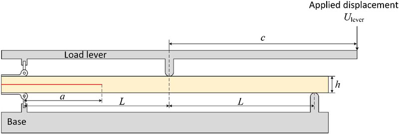
FIGURE 1. Apparatus of the MMB test.
To get rid of this inter-laminar strength dependency, Turon et al. revised their original cohesive constitutive law twice (Turon et al., 2010; Turon et al., 2018), which is one of the mostly used CZMs for simulating delamination in composite structures. In their first update (Turon et al., 2010), a relationship between the pure mode I and mode II inter-laminar strength was given:
where
where K I, K II and K m are the stiffness used in the cohesive law for pure mode I, mode II and mixed-mode with a mode mixity of B, respectively (see details of the cohesive law definition in the next section). With this modified formulation of the cohesive constitutive law, the dependence of the macro-scale response on the inter-laminar strength can be eliminated but only during the delamination propagation after the peak load. The peak load is still affected by the inter-laminar strength, which is against the conclusion of the study of Lu et al. (2019). Lu et al. systematically analyzed the effect of inter-laminar strength on the delamination behavior, and it was found that in the presence of a stress concentration, such as a pre-delamination, the structural response is strength independent including both peak load and the response in the propagation part.
In this paper, a new formulation of a cohesive constitutive law is proposed for simulating delamination with variable mode mixity. The constitutive law is constructed incrementally based on the deformation, traction and mode mixity at the integration point obtained from the previous simulation step. In this way the effect of loading history is included in the cohesive law. For simplicity, the formulation of the proposed cohesive constitutive law is firstly explained for a pure mode condition in Bi-Linear Cohesive Constitutive Law in the Case of a Single Mode, and then extended to the variable mode mixity cases in Cohesive Constitutive Law for Variable Mode Mixity. The developed cohesive constitutive law is validated by simulating MMB test, and the results are shown in Results of FEM Validation and Discussion. Discussions about the mixed-mode constitutive law is also presented in the same section. Finally, Conclusions and Outlook summarizes conclusions and highlights of this study.
Bi-Linear Cohesive Constitutive Law in the Case of a Single Mode
A classical bilinear cohesive law is adopted in this study. It has been utilized many times in the literature both for the simulation of static and fatigue delamination due to its simplicity in implementation (Alfano and Crisfield, 2001; Turon et al., 2006; Kawashita and Hallett, 2012; Nojavan et al., 2016). The bilinear cohesive law developed by Turon (Turon et al., 2006) is widely used for modeling delamination in composite structures, and serves as basis in this study.
In the three-dimensional formulation, the displacement jump δ i and traction σ i of the integration point in cohesive element have three components, one indicating opening deformation and the other two describing shearing deformation. However, in the simulation of a pure mode, only one component of the displacement jump is non-zero and the cohesive law can be simplified to the relation between two scalars: displacement jump and traction for the relevant mode. The bilinear cohesive relation between the jump and the traction consists of two sections: an initial linearly elastic response, which is followed by linear softening. Figure 2A gives a sketch of the bilinear cohesive law. The integration point behaves linearly-elastically with the initial stiffness, K 0, until the initial displacement δ 0 is reached, after which the interface traction σ decreases as the displacement jump increases. The initial displacement, δ 0, is the displacement jump corresponding to the inter-laminar strength of the integration points in cohesive element σ 0: δ 0 = σ 0/K 0. A damage variable, d 0, is defined as the degradation of the initial stiffness, K = (1 − d 0) K 0. The integration point becomes traction free, when displacement jump reaches the critical value δ f .
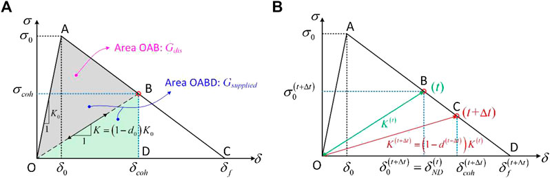
FIGURE 2. Sketch of the bilinear cohesive law: (A) damage variable d 0; (B) incremental type damage variable d (t+Δt).
The traction at the integration point σ coh can be determined as a function of the displacement jump, δ coh, and damage variable, d 0:
The damage variable, d 0, is equal to zero in the elastic region OA, and increases from zero at point A to unity at point C in the softening region AC:
The area under the traction-displacement jump curve (i.e., area OAC in Figure 2A) equals G c , which is the critical energy release rate of the integration point. G c is also interpreted as the inter-laminar fracture toughness. The displacement at which the element becomes traction free (sometimes referred as failure displacement) can be calculated as follows:
The strain energy release rate (SERR), which has been supplied to the cohesive element up to the moment when the displacement jump reaches the value of
The energy dissipated due to accumulated damage, G
dis, is represented by area OAB in Figure 2A. It is the amount of energy that cannot be recovered after unloading:
Based on the traditional bilinear constitutive law, we propose an incremental type of damage variable d
(t+Δt), which describes reduction of stiffness K
(t) to K
(t
+Δt) (Figure 2B). In the following analysis, the superscripts (t) and (t+Δt) indicate the variables that are obtained at time t and t+Δt, respectively. The definition of the incremental type of damage variable allows the cohesive constitutive law to be updated in an incremental way which will be beneficial to the simulation of the case with a variable mode mixity. At simulation time t, the residual stiffness of the cohesive element is K
(t), as simulation time (deformation) progresses the integration point behaves following the constitutive curve O-B-D, as shown in Figure 2B. No reduction of K
(t) happens until the displacement reaches
Here we define a parameter, “no-damage displacement” at time t,
where d
(t) is the damage accumulated between time t − Δt and t;
The initial value of initial displacement at t = 0,
The incremental damage variable, d, stiffness, K, and traction, σ, at time t + Δt can finally be updated as:
With the definition of the incremental type damage variable, the update of constitutive curve is conducted in an incremental way: it is only determined by the constitutive curve at the last simulation step, and the effect of history loading is included.
COHESIVE CONSTITUTIVE LAW FOR VARIABLE MODE MIXITY
In the simulation of mixed-mode delamination, the displacement jump and traction cannot be treated as scalars, and therefore the displacement jump and traction in the cohesive constitutive equation are considered as vectors with three components. With the definition of incremental damage variable, the constitutive equation for a three-dimensional cohesive element can be expressed as follows:
Where subscript i and j denote the mode of deformation: i, j = 1-opening mode (Mode I), i, j = 2-shearing mode (Mode II) and i, j = 3-shearing mode (Mode III); δ
j
(j = 1, 2, 3) is the displacement jump for the corresponding modes; σ
i
(i = 1, 2, 3) is the corresponding traction in each single mode;
With the three-dimensional constitutive law, the mixed-mode deformation can be considered, as a mixture of deformations under different (pure) modes. The isotropic properties are assumed for shear modes (i.e., the plane of Mode II and III), and a displacement jump in general shear mode is defined as the resultant of the two shearing displacement jump:
The corresponding resultant shear traction is calculated as:
An equivalent mixed-mode displacement jump is then defined as the resultant of opening and shearing displacement jump:
The mode mixity B is defined as the ratio of supplied SERR in shear mode to the total supplied SERR:
where
Different from the one-dimensional constitutive law for pure mode simulation, under the mixed-mode load condition, the constitutive law is three-dimensional as shown in Figure 3A by the black curve. It can be decomposed into two independent constitutive curves, representing the cohesive behavior under mode I and the resultant behavior under shear modes, respectively, as shown in Figure 3 by the red and green curves. The subscripts 1, s, and m in Figure 3 represent mode I, general shear mode and mixed-mode, respectively.
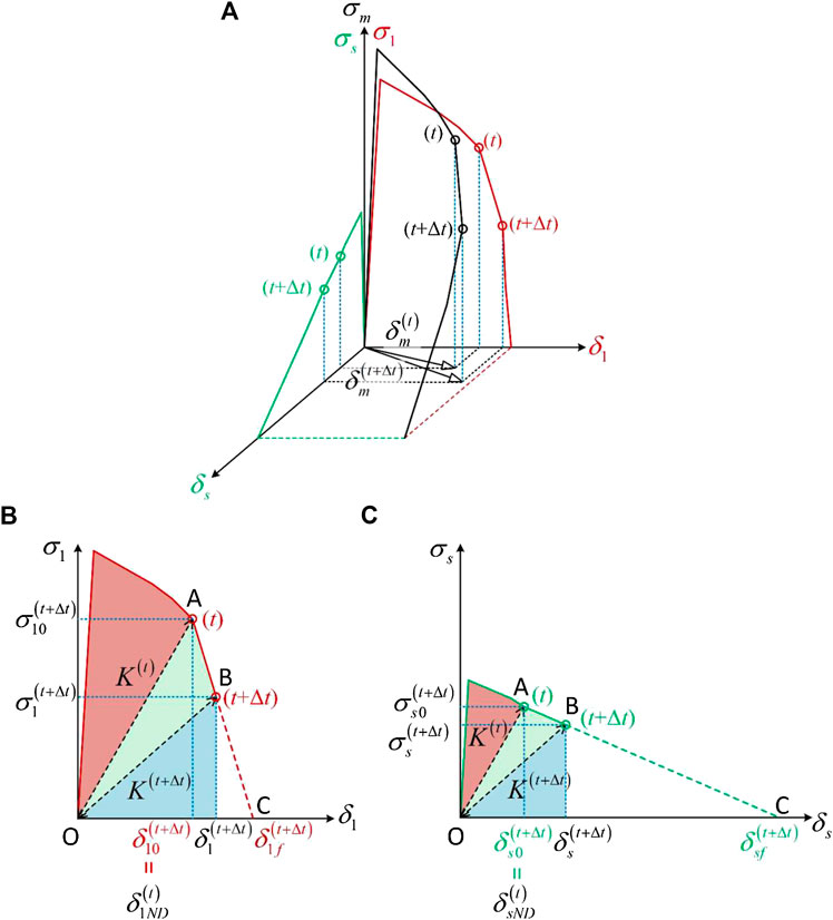
FIGURE 3. Mixed-mode constitutive curve: (A) constitutive curves in the mixed-mode space; (B) decomposition of mixed-mode constitutive curve on the mode I plane; (C) decomposition of the mixed-mode constitutive curve on the shear mode plane.
The development of the cohesive law in the mixed-mode space relies on the cohesive behavior in mode I and the resultant shear mode behavior. Figures 3B,C depicts the decomposed constitutive laws. The areas of the red regions in Figures 3B,C are the dissipated SERR at time t in mode I,
At simulation time t + Δt the displacement jump and traction are updated based on the cohesive law, and the new dissipated SERR is calculated as the green area in Figures 3B,C, and therefore the dissipated SERR at t + Δt is updated as:
The supplied SERR at time t + Δt is equal to the dissipated SERR at time t + Δt plus the area of blue region in Figures 3B,C:
The mode mixity at time t + Δt is then determined by Eq. 18. For the mixed-mode cases with only mode I and mode II deformation, the critical SERR or fracture toughness under such a mode mixity can be obtained by applying B-K criterion (Benzeggagh and Kenane, 1996):
where G c_I and G c_II are the fracture toughness for pure mode I and mode II, and η is a fitting parameter fitted from the experimental results. The validation case in this study is a MMB test, where only the mixture of mode I and II is considered, and therefore the use of B-K criterion is feasible. For those interested to use the proposed mixed-mode cohesive constitutive law to the mixture of all three modes, a different criterion for calculating the fracture toughness may be needed or validation of the B-K criterion first.
The cohesive constitutive law for each single mode should be updated based on the latest mode mixity, i.e., B (t+Δt). However, the determination of B (t+Δt) depends on the updated cohesive law, as described by Eqs 18–21. To avoid the complicated iteration, the mode mixity at time t, B (t), is used as the value of B (t+Δt) for updating the constitutive law at time t + Δt, with an assumption that the mode mixity B doesn’t change significantly if the time increment Δt is small. The updated value of B (t+Δt) is then used to obtain the cohesive law for the next simulation step from time t + Δt to time t + Δt + Δt′. The feasibility of this assumption will be discussed in the next section.
The cohesive law at time t + Δt depends on three variables: the initial stiffness, K
(t), initial displacement,
The displacement for the traction free condition is determined by the residual SERR
The ratio of the critical SERR for the shear modes to the (mixed-mode) fracture toughness also satisfies the definition of mode mixity, which should be identical to the value calculated in Eq. 18:
Substituting Eq. 25 into Eq. 24, the displacements at zero tractions for the opening and shear modes can be obtained as follows:
Once the cohesive law on a single plane is determined, the cohesive law in the mixed-mode space (as shown in Figure 3A) can be updated. The mixed-mode initial displacement and failure displacement are calculated as the resultant of the ones under a single mode, namely
Besides the stiffness tensor, K
ij
, defined by cohesive constitutive law in Eq. 14, a tangent tensor,
where
Substituting Eq. 28 into Eq. 27, the tangent tensor is calculated as:
Results of FEM Validation and Discussion
The developed formulation of the mixed-mode cohesive constitutive law is tested by simulating mixed-mode delamination in fibre-reinforced composites. The incremental mixed-mode cohesive law was implemented into the cohesive element as a user-defined material (UMAT) subroutine in FE software Abaqus Implicit. In the simulation, 8-node solid element C3D8I was chosen for modeling composite plies and 8-node cohesive element COH3D8 was applied to the inter-laminar interface. The cohesive elements have a zero thickness.
FEM Model Description
The MMB test defined in ASTM D6671 (ASTM D6671, 2013) is frequently used to characterize the mixed-mode delamination behavior, as shown in Figure 1. The MMB test set-up is designed such as to combine Mode I and II loadings. The supplied SERR at the crack tip can be calculated as (Reeder and REWS, 1990):
where G I and G II are the Mode I and II components of SERR; G m is the total mixed-mode SERR; P lever is the applied load at the end of the load lever; a is the crack length; b and h are the specimen width and half thickness, L is the half span length, and c is the lever length, χ is the crack length correction parameter calculated by Eq. 3, and E 1f is the bending modulus of the composite:
where C is the compliance obtained from the load displacement curve. The mode mixity B at the specimen level is then calculated as B = G II/G m .
The displacement applied at the end of the specimen U end, in the middle point U mid and at the end of the load lever U lever satisfy the following relation (Camanho et al., 2003):
The model to simulate the MMB test is shown in Figure 4. To simplify the simulation, the displacement is applied at three positions respectively, instead of simulating the load lever explicitly. A constraint equation is defined to meet the boundary condition defined by Eq. 32, which can be viewed as the application of a virtual load lever.
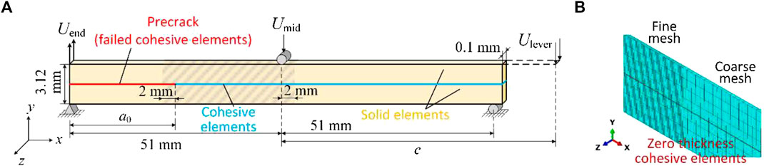
FIGURE 4. Modeling MMB specimen in FEM: (A) geometry of the model and boundary conditions; (B) zoom-in view of the mesh.
The same geometry of MMB specimen simulated by Turon et al. (2018) is used in this study. It is 102.0 mm long and 3.12 mm thick with a precrack placed at the middle plane. The material properties of the laminate are listed in Table 1.
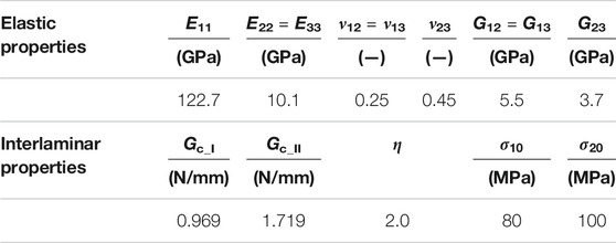
TABLE 1. Material properties of AS4/PEEK UD laminates (Turon et al., 2010).
The details of the geometry model and applied boundary conditions are illustrated in Figure 4. A layer of cohesive elements with damage variable d = 1 are placed at the position of the pre-crack to simulate the traction free surface, which cannot hold tension or shear but compression to prevent the penetration between the upper and lower arms. The potential path for the delamination propagation is simulated as one layer of cohesive elements with the incremental cohesive constitutive law proposed in Cohesive Constitutive Law for Variable Mode Mixity and the input parameters of the law are reported in Table 1. The upper and lower arms of MMB specimen were simulated by solid elements. To accelerate the simulation, only one element is placed along the width direction of the specimen, i.e., z direction in Figure 4, and the width of the model was equal to the element width 0.1 mm. A state of generalized plane strain was assumed in the width direction: the front and back edges of the model were kept parallel during the deformation. This assumption means that the displacement δ z is constant throughout the x-y plane of the model. A fine mesh along the x direction, was set at the end of the pre-crack and beginning of the potential delamination path, depicted as gray zone in Figure 4. The preliminary mesh sensitivity study shows that the simulation result is not sensitive to the mesh size when it is smaller than 0.05 mm. Therefore, a value of 0.05 was chosen as the refined mesh size. Coarse mesh was used in the other parts, where the element length was 0.2 mm. Four layers of solid elements were placed along the thickness direction, i.e., y direction, on the upper and lower arms respectively.
The MMB test with a mode mixity B at the specimen level equal to 20%, 50% and 80% are simulated. According to 30 and 31a, the corresponding pre-crack length a 0 and lever length c are listed in Table 2. The displacement is applied at the end of the load lever U lever, and the reaction force obtained at the same position is recorded.
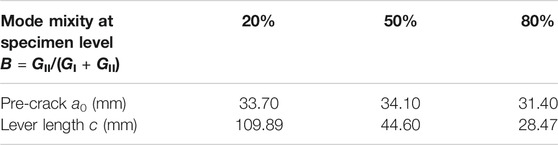
TABLE 2. Geometry parameters of MMB tests.

TABLE 3. Four sets of values for the interlaminar strength used in the simulation.
Effect of the Inter-Laminar Strength
The analytical solution of the reaction force and displacement can be obtained by Eqs 1–3 based on LEFM (ASTM D6671, 2013). Four sets of values for the inter-laminar strength were chosen in this study for testing its effect on the delamination growth at a specimen level (Table 3).
The inter-laminar strength in Set1 is used by Turon. et al. (2006) for carbon fiber/PEEK composite AS4/PEEK; the strengths in Set2 is determined to satisfy the condition defined by Eq. 4 to eliminate the strength dependency in Turon’s model (Turon et al., 2010); the values in Set3 and Set4 are chosen arbitrarily. The resulting reaction force-displacement curves with these different sets of the inter-laminar strength are plotted in Figure 5, where the reaction force at the lever end is expressed as the linear force along the width direction (i.e., z direction). No matter which set of inter-laminar strength is used, the simulation results meet with each other and all have a good agreement with the analytical solution under all the mode mixity load conditions. In the simulations of mode mixity B equal to 50% and 80%, there is no dependence of structural response on the selected inter-laminar strength. In the case of B = 20%, the selection of inter-laminar strength only has a minor effect on the maximum force, and the largest difference on the maximum force is 2.22%. The propagation behavior i.e., structural response after the maximum load, has no dependence on the strength value in this case. With the developed cohesive constitutive law, there is no need to select a special strength value for a correct mixed-mode delamination behavior.
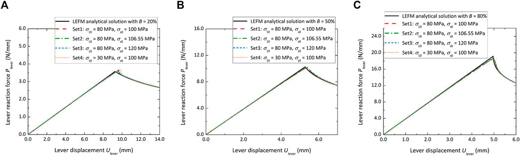
FIGURE 5. The dependence of the load-displacement curve on the inter-laminar normal and shear strength with: (A) mode mixity of 20%; (B) mode mixity of 50%; (C) mode mixity of 80%.
In this study, the mode mixity is calculated using the supplied SERR, which is as the ratio between the supplied SERR for shearing to the total supplied SERR expressed by Eq. 18. This is identical to the definition of the mode mixity described in the MMB test standard (ASTM D6671, 2013). The definition of the mode mixity used by Turon et al. (2006) is based on the displacement jump:
Variable Mode Mixity at the Integration Point
MMB test is designed for characterizing the mixed-mode delamination behavior under fixed mode mixity at specimen level. The mode mixity is determined by specimen geometry, the lever length c and material elastic properties, as depicted by Eq. 30. In the current simulations, all these parameters are fixed to obtain a mode mixity of 20%, 50% and 80% at specimen level. However, the mode mixity at the integration point does not stay constant during the loading process. This phenomenon has also been observed by Turon et al. (2010).
To illustrate how the mode mixity changes, it was evaluated at the integration point 5 mm away from a pre-crack tip during the whole loading history. It is shown in Figure 6, where the x axis is the normalized displacement jump (that includes both normal and shear displacements) at the integration point. The displacement jump is normalized by the value of the displacement jump when the traction at the integration point is zero. As shown in Figure 6, similarly to the observation of Turon et al. (2010), the mode mixity is not fixed as the beam theory at specimen level predicts. Instead it decreases monotonically approaching the level close to the one defined at the specimen level when the integration point becomes traction free, i.e., 20%, 50% and 80% for Figures 6A–C, respectively. Because the predicted structural behavior from the proposed cohesive law has little sensitivity to the inter-laminar strength, the discrepancy of mode mixity at the specimen level and at the integration point level cannot be attributed to the dependence of delamination behavior on the inter-laminar strength, which was used to explain the dependence of predicted load-displacement on the selection of the inter-laminar strength in Turon’s study (Turon et al., 2010).
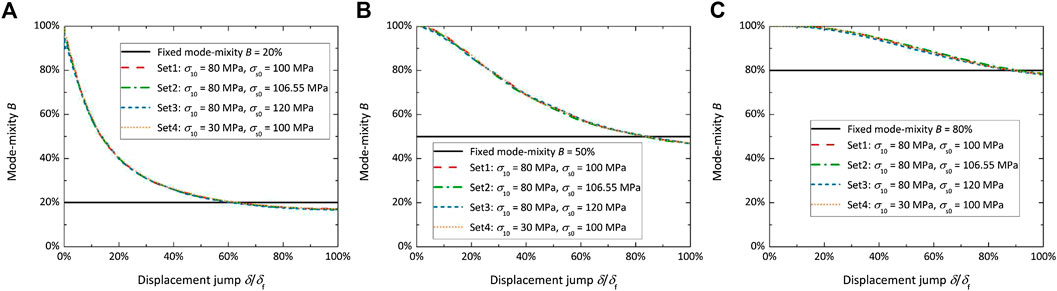
FIGURE 6. Change of the mode mixity at the integration point which is 5 mm away from the pre-crack tip with: (A) mode mixity of 20%; (B) mode mixity of 50%; (C) mode mixity of 80%.
Mixed-Mode Constitutive Law at Integration Point
Due to the variable mode mixity at the integration point, the constitutive behavior obtained at the integration point also differs from the one for a fixed mode mixity. Figure 7 shows the mixed mode constitutive law at the integration point which is 5 mm to a pre-crack tip. The mixed mode constitutive law at the integration point deviates from the typical triangle shape for the case of a fixed mode mixity. The total SERR dissipated when the integration point becomes traction free is output, which can be considered as the fracture toughness of the interface under such a load condition. The values of fracture toughness used in LEFM analysis for the fixed mode mixity defined at specimen level are also listed. It can be found that these two values agrees with each other for all the mode mixities and sets of inter-laminar strengths, as listed in Table 4. The similar values of fracture toughness output from FEM and used in LEFM analysis for fixed mode mixity at specimen level explains why the predicted reaction force-displacement curve at specimen level has a good agreement with the LEFM analysis even if the mode mixity at integration point deviates from the one defined at specimen level for all the mode mixities and selections of inter-laminar strengths.
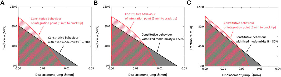
FIGURE 7. Comparison of the constitutive law output from the integration point 5 mm away from the pre-crack tip to the one for the fixed mode mixity with: (A) mode mixity of 20%; (B) mode mixity of 50%; (C) mode mixity of 80%.
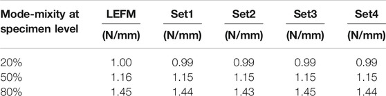
TABLE 4. Fracture toughness of interface output from different simulation cases.
Feasibility of the Assumption of Small Mode Mixity Change
In Cohesive Constitutive Law for Variable Mode Mixity, an assumption was made for simplifying the development of three-dimensional cohesive constitutive law: the change of mode mixity is small, and therefore the mode mixity obtained from previous simulation step is directly used as the mode mixity for the current simulation increment. The error between the actual mode mixity in the simulation increment and the value used for developing the cohesive law for this simulation increment is calculated, as shown in Figure 8. The results are from the simulation with the inter-laminar strengths from Set1. It can be found that the error of the mode mixity is always below 7% for all the mode mixities.
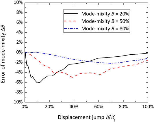
FIGURE 8. Error of mode mixity from the assumption of small change of mode mixity.
Conclusion and Outlook
A new formulation of a cohesive constitutive law was developed in this study, which is capable of simulating delamination with variable mode mixity and has little sensitivity to the inter-laminar strength. An incremental type of damage variable is proposed, a factor accounting for the reduction of the residual stiffness in the traction-displacement cohesive law. It allows updating the constitutive law step by step (incrementally) and includes the effect of loading history. The mode mixity at the integration point is updated during the loading, and calculated in the formulation of the supplied SERR.
The model was validated by simulating MMB test with three different mode mixities. Simulations were run for four different values of the inter-laminar strength, and for these simulation cases, the reaction force-displacement for the loaded MMB specimen has a good agreement with the analytical solution from LEFM analysis. There is only a minor dependence on the inter-laminar strength. In the case of B = 20% the largest difference in the maximum load is 2.22%, and this dependence disappears in the propagation part after the maximum load. The dependence on the strength is eliminated in the simulations with mode mixity of 50% and 80%. The mode mixity at the integration point is found to be different from the constant mode mixity applied macroscopically at the specimen level. However, the total SERR dissipated (up to the displacement when the integration point becomes traction free) is almost equal to the fracture toughness input to LFEM analysis for the fixed mode mixity at specimen level and is independent of the inter-laminar strength. The agreement of the output fracture toughness with the fracture toughness used in LEFM analysis for fixed mode mixity at specimen level explains the correctly predicted reaction force-displacement curve for all the studied cases.
For those who are interested to perform characterization under true constant mode-mixity conditions Sørensen et al. (2006) proposed a test method where a double cantilever beam specimen is loaded with uneven bending moments (DCB-UBM). An FEM study of the DCB-UBM test with the proposed incremental cohesive law would be interesting to confirm that the mode mixities are indeed the same at the macro- and micro-scale in this test.
The validation case in this study is an MMB test, for which experimental data are available. A case study with all three modes of delamination supported by experimental data is needed to complete the validation of the proposed mixed-mode cohesive law.
Data Availability Statement
The raw data supporting the conclusions of this article can be made available upon request by the authors, without undue reservation.
Author Contributions
MZ: model development, simulation, analysis, article writing; LG: data interpretation, supervision, article editing; SL: data interpretation, supervision, article editing.
Funding
The work has been funded by the SBO project “M3Strength,” which fits in the MacroModelMat (M3) research program, coordinated by Siemens (Siemens Digital Industries Software, Belgium) and funded by SIM (Strategic Initiative Materials in Flanders) and VLAIO (Flanders Innovation & Entrepreneurship). S.V. Lomov holds Toray Chair for Composite Materials at KU Leuven, support from which is gratefully acknowledged.
Conflict of Interest
The authors declare that the research was conducted in the absence of any commercial or financial relationships that could be construed as a potential conflict of interest.
References
Alfano, G., and Crisfield, M. A. (2001). Finite element interface models for the delamination analysis of laminated composites: mechanical and computational issues. Int. J. Numer. Methods Eng. 50, 1701–1736. doi:10.1002/nme.93
ASTM D6671/D6671M-13 (2013). Standard test method for mixed mode I-mode II interlaminar fracture toughness of unidirectional fiber reinforced polymer matrix composites. West Conshohocken, PA: ASTM International.
Barenblatt, G. I. (1959). The formation of equilibrium cracks during brittle fracture. General ideas and hypotheses. Axially-symmetric cracks. J. Appl. Math. Mech. 23, 622–636. doi:10.1016/0021-8928(59)90157-1
Barenblatt, G. I. (1962). The mathematical theory of equilibrium cracks in brittle fracture. Adv. Appl. Mech. 7, 55–129. doi:10.1016/s0065-2156(08)70121-2
Bennati, S., Fisicaro, P., and Valvo, P. S. (2013a). An enhanced beam-theory model of the mixed-mode bending (MMB) test-part I: literature review and mechanical model. Meccanica 48, 443–462. doi:10.1007/s11012-012-9686-3
Bennati, S., Fisicaro, P., and Valvo, P. S. (2013b). An enhanced beam-theory model of the mixed-mode bending (MMB) test-part II: applications and results. Meccanica 48, 465–484. doi:10.1007/s11012-012-9682-7
Benzeggagh, M. L., and Kenane, M. (1996). Measurement of mixed-mode delamination fracture toughness of unidirectional glass/epoxy composites with mixed-mode bending apparatus. Compos. Sci. Technol. 56, 439–449. doi:10.1016/0266-3538(96)00005-x
Borg, R., Nilsson, L., and Simonsson, K. (2002). Modeling of delamination using a discretized cohesive zone and damage formulation. Compos. Sci. Technol. 62, 1299–1314. doi:10.1016/s0266-3538(02)00070-2
Camanho, P. P., Davila, C. G., and De Moura, M. F. (2003). Numerical simulation of mixed-mode progressive delamination in composite materials. J. Compos. Mater. 37, 1415–1438.
De Moura, M. F. S. F., Gonçalves, J. P. M., and Silva, F. G. A. (2016). A new energy based mixed-mode cohesive zone model. Int. J. Solid Struct. 102-103, 112–119. doi:10.1016/j.ijsolstr.2016.10.012
Dugdale, D. S. (1960). Yielding of steel sheets containing slits. J. Mech. Phys. Solid. 8, 100–104. doi:10.1016/0022-5096(60)90013-2
González, E. V., Maimí, P., Camanho, P. P., Turon, A., and Mayugo, J. A. (2012). Simulation of drop-weight impact and compression after impact tests on composite laminates. Compos. Struct. 94, 3364–3378. doi:10.1016/j.compstruct.2012.05.015
Gözlüklü, B., and Coker, D. (2012). Modeling of the dynamic delamination of L-shaped unidirectional laminated composites. Compos. Struct. 94, 1430–1442. doi:10.1016/j.compstruct.2011.11.015
Gozluklu, B., Uyar, I., and Coker, D. (2015). Intersonic delamination in curved thick composite laminates under quasi-static loading. Mech. Mater. 80, 163–182. doi:10.1016/j.mechmat.2014.07.013
Harper, P. W., Sun, L., and Hallett, S. R. (2012). A study on the influence of cohesive zone interface element strength parameters on mixed mode behaviour. Compos. Appl. Sci. Manuf. 43, 722–734. doi:10.1016/j.compositesa.2011.12.016
Jensen, S. M., Martos, M. J., Bak, B. L. V., and Lindgaard, E. (2019). Formulation of a mixed-mode multilinear cohesive zone law in an interface finite element for modelling delamination with R-curve effects. Compos. Struct. 216, 477–486. doi:10.1016/j.compstruct.2019.02.029
Joki, R. K., Grytten, F., Hayman, B., and Sørensen, B. F. (2016). Determination of a cohesive law for delamination modelling-accounting for variation in crack opening and stress state across the test specimen width. Compos. Sci. Technol. 128, 49–57. doi:10.1016/j.compscitech.2016.01.026
Kawashita, L. F., and Hallett, S. R. (2012). A crack tip tracking algorithm for cohesive interface element analysis of fatigue delamination propagation in composite materials. Int. J. Solid Struct. 49, 2898–2913. doi:10.1016/j.ijsolstr.2012.03.034
Liu, Q., Gorbatikh, L., and Lomov, S. V. (2019). A combined use of embedded and cohesive elements to model damage development in fibrous composites. Compos. Struct. 223, 110921. doi:10.1016/j.compstruct.2019.110921
Lu, X., Ridha, M., Chen, B. Y., Tan, V. B. C., and Tay, T. E. (2019). On cohesive element parameters and delamination modelling. Eng. Fract. Mech. 206, 278–296. doi:10.1016/j.engfracmech.2018.12.009
Nojavan, S., Schesser, D., and Yang, Q. D. (2016). A two-dimensional in situ fatigue cohesive zone model for crack propagation in composites under cyclic loading. Int. J. Fatig. 82, 449–461. doi:10.1016/j.ijfatigue.2015.08.029
Reeder, J. R., and Crews, J. H. (1990). Mixed-mode bending method for delamination testing. AIAA J. 28, 1270–1276. doi:10.2514/3.25204
Sørensen, B. F., Jørgensen, K., Jacobsen, T. K., and Østergaard, R. C. (2006). DCB-specimen loaded with uneven bending moments. Int. J. Fract. 141, 163–176. doi:10.1007/s10704-006-0071-x
Turon, A., Camanho, P. P., Costa, J., and Dávila, C. G. (2006). A damage model for the simulation of delamination in advanced composites under variable-mode loading. Mech. Mater. 38, 1072–1089. doi:10.1016/j.mechmat.2005.10.003
Turon, A., Camanho, P. P., Costa, J., and Renart, J. (2010). Accurate simulation of delamination growth under mixed-mode loading using cohesive elements: definition of interlaminar strengths and elastic stiffness. Compos. Struct. 92, 1857–1864. doi:10.1016/j.compstruct.2010.01.012
Keywords: cohesive law, delamination, mixed mode, composite, finite element method
Citation: Zhu M, Gorbatikh L and Lomov SV (2020) An Incremental Cohesive Law for Delamination Under a Mixed Mode Loading. Front. Mater. 7:572995. doi: 10.3389/fmats.2020.572995
Received: 15 June 2020; Accepted: 02 October 2020;
Published: 12 November 2020.
Edited by:
Patricia Krawczak, IMT Lille Douai, FranceReviewed by:
Frédéric Lachuad, Institut Supérieur de l’Aéronautique et de l’Espace (ISAE-SUPAERO), FrancePaolo S. Valvo, University of Pisa, Italy
Copyright © 2020 Zhu, Gorbatikh and Lomov. This is an open-access article distributed under the terms of the Creative Commons Attribution License (CC BY). The use, distribution or reproduction in other forums is permitted, provided the original author(s) and the copyright owner(s) are credited and that the original publication in this journal is cited, in accordance with accepted academic practice. No use, distribution or reproduction is permitted which does not comply with these terms.
*Correspondence: Larissa Gorbatikh, larissa.gorbatikh@kuleuven.be