Behaviors of Large-Rupture-Strain Fiber-Reinforced Polymer Strengthened Reinforced Concrete Beams Under Static and Impact Loads
 Zenghui Ye
 Debo Zhao
 Lili Sui1
  Zhenyu Huang
 Xiaoqing Zhou
- 1College of Civil and Transportation Engineering, Shenzhen University, Shenzhen, China
- 2Key Laboratory of Coastal Urban Resilient Infrastructures (MOE), Shenzhen University, Shenzhen, China
Reinforced concrete (RC) structures may be damaged seriously when subjected to impact loading, and it is necessary to strengthen existing structures to improve their impact resistance. Large-rupture-strain fiber-reinforced polymer (LRS-FRP) is a promising material to strengthen RC structures under impact because of its good deformation capacity. This article shows experimental studies on performance of LRS-FRP strengthened RC beams under static and impact loads. The effects of FRP types, loading rate, and the usage or nonusage of end-anchorages on the strengthening efficiency were investigated. The experiment demonstrates LRS-FRP laminate with end-anchorage (EA) to be an appropriate strengthening technique for RC beams under both static and impact loading. The beams strengthened with end-anchored LRS-FRP presented greater ductility than their carbon fiber-reinforced polymer counterpart under static loading, and the end-anchored LRS-FRP strengthening system reduced the maximum deflection and damage of strengthened beam under impact significantly. However, the end-anchorage was more susceptible to damage and failure when the loading rate increased from static to impact. Therefore, the end-anchorage and the end-anchorage-FRP connection should be designed with caution for impact condition.
Introduction
Fiber-reinforced polymer (FRP) is widely accepted as an excellent material in structural strengthening and retrofitting because of its high strength-to-weight ratio, good corrosion resistance, and ease of installation (Teng et al., 2002, Teng et al., 2012; Baji et al., 2016; Nie et al., 2020; Zhou et al., 2020a). Externally bonded (EB) FRP technique was used for flexural and shear strengthening (Bencardino et al., 2005; Bencardino et al., 2006; Chen et al., 2018; Benzeguir et al., 2020; Chen et al., 2020; Li et al., 2020). Generally, FRP laminates are used for flexural strengthening, and transverse FRP sheets are used for shear strengthening. Conventional types of FRP include carbon-FRP (CFRP), glass-FRP (GFRP), and aramid-FRP (AFRP), etc. A great number of studies show that FRP strengthening can effectively enhance the bearing capacity and stiffness of RC beams (Bencardino et al., 2005; Bencardino et al., 2006; Oller et al., 2019; Benzeguir et al., 2020; Sayed, 2020), and detailed procedures have been established to guide the design of FRP strengthened RC beams (ACI 440.2R-17, 2017; CNR-DT 200 R1/2013, 2013). However, the bearing capacity and ductility of FRP strengthened RC structures are commonly controlled by the debonding of FRP, which limits the utilization efficiency of FRP materials and makes the mechanical behavior of strengthened beam more brittle (Bencardino et al., 2006). Therefore, the allowable strain of FRP is strictly restricted in design codes to prevent the FRP–concrete interface failure (CNR-DT 200 R1/2013, 2013; ACI 440.2R-17, 2017; CAN/CSA S806-12 (R2017), 2017). Many studies (Bencardino et al., 2005; Bencardino et al., 2006; Dai et al., 2009; Kalfat and Al-Mahaidi, 2011; Zhou et al., 2017; Zhou et al., 2018; ) show that applying additional mechanical anchors on the EB-FRP laminate can improve the collaboration ability of the FRP strengthening system with the RC beam greatly, and thus inhibits or prevents the failure induced by FRP debonding. For strengthened beams with EB-CFRP laminates, the end-anchorage design plays an important role in restoring a substantial part of the lost ductility property, but is unable to restore the strengthened beams to the original levels of ductility (Bencardino et al., 2006). Different types of anchorage have been developed, such as mechanical fastener, end-anchorage, U-wrap FRP, and FRP spike anchor (Kalfat et al., 2013). With the appropriate arrangement of anchorage, the bearing capacity of the strengthened beam can be enhanced significantly (El Maaddawy and Soudki, 2008; Zhang and Smith, 2012; Zhang and Smith, 2017; Zhou et al., 2018). Therefore, the anchorage techniques are recommended by many design codes to address the FRP debonding issue (CECS-146, 2003; GB 50608–2010, 2010; GB 50367–2013, 2013; ACI 440.2R-17, 2017).
Compared with rich research results at static loading, only a few studies have been performed to investigate the dynamic behavior of FRP strengthened RC beams under impact loading. The experiments performed by Pham and Hao (2017) showed that FRP strengthening enhanced the impact resistance of RC beam remarkably, decreased the maximum mid-span deflection, and prevented the development of concrete cracks. However, it is also found that the strengthening beams under impact loading were prone to failing in FRP debonding, and the debonding strains were generally lower than those in static tests (Pham and Hao, 2016; Pham and Hao, 2017). To inhibit the FRP debonding failure under impact, Pham and Hao (2017) performed drop-weight tests to RC beams strengthened by longitudinal FRP strips and FRP U-wraps, where the FRP U-wraps were designed to apply confinement on longitudinal FRP laminate. The experimental results showed that the lateral confinement can effectively enhance the capability of longitudinal FRP strips, although it cannot completely prevent the FRP debonding phenomenon. Moreover, drop-weight tests of CFRP strip-wrapped RC beams without stirrups also demonstrated that the lateral FRP confinement effectively reduced the deflection and damage (Liu and Xiao, 2017). Specifically, the retrofit with CFRP wrap equal to a reinforcement ratio half of that required by the ACI specification (ACI 440.2R-17, 2017) was able to prevent shear failure up to impact loading with more than four times the energy as static energy-dissipation capacity (Liu and Xiao, 2017). However, at the initial stage of the impact, the stress and deformation concentrated at the impacting point due to the strong influence of inertial force. The shear deformation concentrating at the impact point created inclined cracks with large widths, forming a shear plug, and the lateral CFRP strips at this zone were prone to rupturing because of the small rupture strain of CFRP material (Liu and Xiao, 2017).
Large rupture strain FRP (LRS-FRP), as an emerging strengthening material, has a much larger rupture strain (>5%) than conventional FRPs. It is also a recyclable and environmental friendly material because it is woven from polyethylene naphthalene (PEN) or polyethylene terephthalate (PET) fibers, which can be manufactured from waste products such as plastic bottles. The excellent deformation capability of LRS-FRP offsets the weakness of conventional FRPs, and thus, strengthening RC members with LRS-FRP can enhance the ductility and energy-absorption capacity significantly (Dai et al., 2011; Yu et al., 2017; Baasankhuu et al., 2020). Existing researches indicated that concrete columns confined with LRS-FRP presented ample ductility and thus are especially suitable for high seismic regions (Anggawidjaja et al., 2006; Liu and Li, 2018; Zhao et al., 2019; Zhou et al., 2020b). Saleem et al. (2017) investigated the influence of corner radius on LRS-FRP confined concrete column by conducting compressive tests of specimens with different cross-sectional shapes (circular, square, and rectangular), and the experimental results showed that owing to the low elastic modulus and large rupture strain properties of LRS-FRP, the stress concentration of sharp corners in noncircular columns was efficiently relieved and resisted. The experiment of PET fully wrapped RC beam also indicated that strengthening RC members with PET-FRP increased the ductility of shear failure and prevented the beam from failing by FRP rupture (Jirawattanasomkul et al., 2014). The outstanding deformation capacity of LRS-FRP makes it a potential material for anti-impact retrofitting, but the studies in this field are scarce. Bai et al. (2020) conducted dynamic tension tests of PET fiber bundles and found that the tensile strength of PET fiber bundle was sensitive to the strain rate, which was attributed by the authors to the change of failure modes at varying loading rates. Moreover, the concrete column confined by LRS-FRP also presented much-improved ductility under impact loading compared to the CFRP confined counterparts (Bai et al., 2019).
To further investigate the impact-resistance performance of LRS-FRP strengthened RC structures, this study conducted drop-weight tests of PEN-FRP strengthened RC beams, and investigated the influences of FRP types, loading rate, and the effectiveness of end-anchorages on the strengthening system. Dynamic response characteristics and failure mechanisms of the strengthened beams were analyzed and discussed based on the experimental data. The results presented here can provide references for evaluation and improvement of the anti-impact performance of LRS-FRP strengthened RC structures.
Experimental Program: Specimen Design
The experimental program includes four static-loading specimens and three impact-loading specimens. All specimens had identical dimensions and reinforcements. As shown in Figure 1, the dimensions of the specimens were 150 × 250 × 3,000 mm, and the clear span of the beam was 2,500 mm. Details of the specimens are listed in Table 1. Based on the strengthening methods, the specimens were classified into control specimen without strengthening (C), specimens strengthened with externally bonded PEN-FRP plates (EP), specimens strengthened with end-anchorage PEN-FRP system (AP), and specimens strengthened with end-anchorage CFRP system (AC). The PEN-FRP laminate had two plies of FRP with a width of 60 mm and one-ply thickness of 0.848 mm, whereas the CFRP strip had four plies of FRP with a width of 50 mm and one-ply thickness of 0.167 mm. The PEN-FRP and CFRP laminates were designed to have equal ultimate tensile forces. The CFRP laminate with a cross-sectional area of 33.4 mm2 provided an ultimate force of 131 kN, whereas that of PEN-FRP laminate with a cross-sectional area of 101.8 mm2 was 128 kN. The four static-loaded specimens corresponded respectively with the above-mentioned four strengthening methods, and these specimens were denoted by the strengthening method followed by “-S.” Meanwhile, only end-anchorage FRP strengthened specimens were tested by drop-weight impact. Two specimens were tested with a 516 kg drop-weight with an impact velocity of 4.6 m/s (impact condition 1), whereas the other one was impacted by a 1,016 kg drop-weight with 3.4 m/s velocity (impact condition 2). The naming rule of the impact-loaded specimens was “strengthening method-D-impact condition.” For example, the specimen AP-D2 denotes that the beam was strengthened with end-anchorage PEN-FRP laminate, and the impact weight and velocity were 1,016 kg and 3.4 m/s, respectively. For all strengthened specimens with end-anchorage, an overlapping area of length 300 mm was designed to firm the connection between FRP and end-anchorage. Preliminary tests found that stress concentration at the end-anchorage may cause failure in this area, so additional mechanical fasteners were mounted at overlap sections of the FRP laminate for specimen AC-D1 and AP-D2 to enhance the anchoring effect, as illustrated in Figure 1. The details of the end-anchorage and the mechanical fasteners are illustrated in Figure 1C.
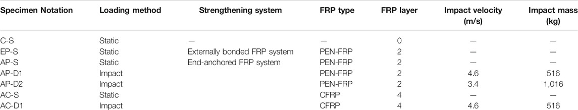
TABLE 1. Details of specimens.
Material Properties
The average 28-day compressive strength of three 100 mm concrete cubes was obtained as 33.6 MPa, per ASTM C39/39M (2005). Table 2 lists the measured material properties of three samples of each type of rebars according to ASTM E8/E8M-11 (2011). The yield strengths of longitudinal rebars at the bottom (14 mm diameter) and top (8 mm diameter) were 433 and 375 MPa, respectively, whereas that of the 8 mm stirrup was 315 MPa. Low-carbon soft steel (Q235) was used to make the end-anchorage and mechanical fasteners, whose yield strength was 268 MPa. The material properties of the CFRP and PEN-FRP collected from coupon testing are summarized in Table 3. The tensile coupon tests of CFRP and PEN-FRP sheets were conducted according to ASTM D3039–18 (2017), and the obtained stress–strain curves are shown in Figure 2. The CFRP presented a linear elastic behavior with the elastic modulus of 248.9GPa and the ultimate strain of 15359με, whereas the PEN-FRP has a bilinear stress–strain relationship, similar to what had been reported in a previous study (Dai et al., 2011). The tangential modulus of PEN-FRP of the first and second segments was 33.1 and 18.3 GPa, respectively, and the ultimate strain was 65,274 με. The modulus and tensile strength of epoxy resin provided by the manufacturer were 3.1 GPa and 41.4 MPa, respectively.
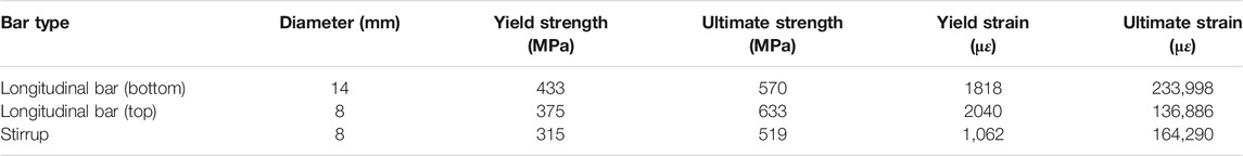
TABLE 2. Mechanical properties of steel bars.
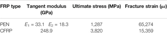
TABLE 3. Mechanical properties of FRPs.
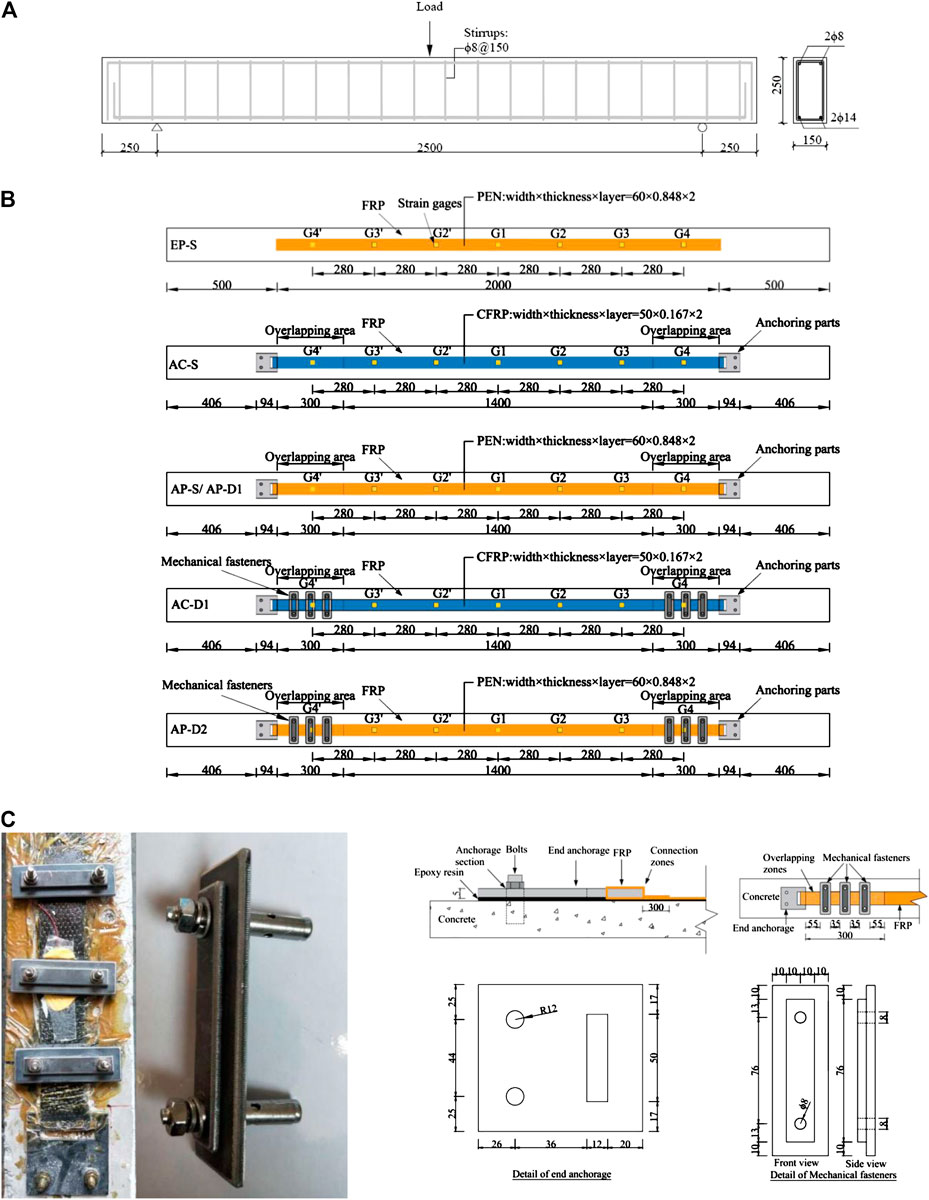
FIGURE 1. Details of tested specimens. (A) Configuration and reinforcement details. (B) FRP strengthening system. (C) Details of end-anchorage and mechanical fasteners.
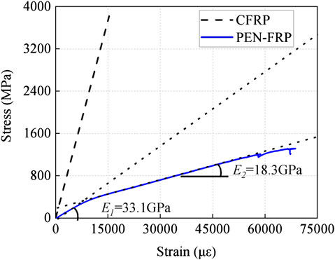
FIGURE 2. Stress–strain relationships of CFRP and PEN-FRP sheets.
Experimental Setup and Instrumentation
The static tests were conducted with an electrohydraulic servo system with a loading rate of 0.5 mm/s. The arrangements of strain gages and linear variable differential transformers (LVDTs) are illustrated in Figure 3A. Seven strain gages were glued to the FRP laminate along the longitudinal direction with a spacing of 280 mm.
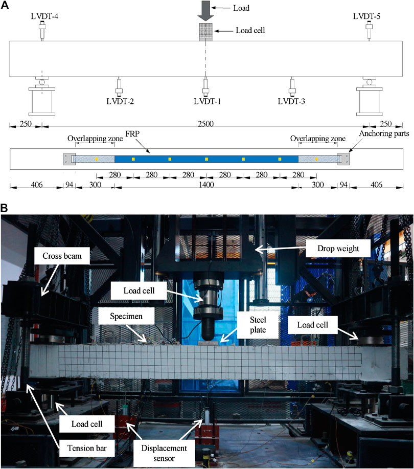
FIGURE 3. Experimental setup. (A) Static loading test. (B) Impact loading test.
The dynamic loading specimens were tested with a drop-weight machine, as shown in Figure 3B. The striking head of the drop hammer had a hemispherical tip with a radius of 50 mm. A load cell was mounted at the neck of the drop hammer to measure the impact force. To prevent the severe local damage at the impact point, a 150 mm square steel plate with a thickness of 30 mm was placed at the top of the beam mid-span. All the specimens were tested with the simply supported condition. To prevent the uplifting movement of the beam ends at impact, a cross beam was placed on the top of the beam at the support, and two steel bars connected with the cross beam were bolted on the support. By applying pretightening forces on the steel bars, the beam was gripped firmly at the support. The arrangement of strain gages and LVDTs for the impact specimens was the same as that of static loading beams. Load cells were placed on the top and bottom of the specimen at the supports to measure the support force. Four accelerometers were installed at the beam side face along the longitudinal direction to obtain the acceleration of the specimen during the collision. All the signals were collected with a data acquisition system with a sampling rate of 500 kHz. The impact process was recorded with two high-speed cameras from different perspectives: one camera with a frame rate of 5,000 fps focused on the side face of the beam, whereas the other one with a frame rate of 1,000 fps focused on the soffit of the beam to record the failure process of the end-anchorage FRP (EA-FRP) system.
Test Results and Discussion
Failure Patterns
Overall Failure Patterns
Figure 4 shows the overall failure patterns of all specimens. The numbers alongside the cracks of dynamic-loading specimens indicate the crack width in millimeters. For static specimens C-S and AP-S, typical flexural failure modes were presented and the final failure was marked by the concrete crushing and the buckling of the upper longitudinal bars at the compressive zone near the loading plate. Specimen EP-S failed due to the debonding of the PEN-FRP laminate, and at that moment, the specimen had much less damage and smaller deformation than C-S and AP-S, indicating that the flexural capacity of the beam was not fully utilized. The failure of specimen AC-S was controlled by the FRP rupture at the connection between end-anchorage and CFRP laminate, and the damage state of the beam was similar to that of EP-S.
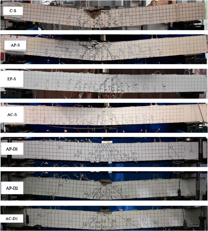
FIGURE 4. Overall failure patterns.
The failure patterns of impact-loading specimens were quite different from those of static ones. The cracks mainly concentrated at the impact zone, forming a plastic hinge, whereas few cracks were observed elsewhere, which coincides with the experimental observation of Fujikake et al. (2009). Moreover, it is notable that specimens under impact had tiny cracks initiating from the top of the beam around the quarter span, which had not been observed in the static tests. Premature failure of the end-anchorage occurred in specimen AC-D1 during the impact process, so the beam had more obvious deformation and cracks than AP-D1. Moreover, the inclined cracks near the impact point of AC-D1 had small inclined angles than those of AP-D1, and the crack near the quarter span seemed to be more developed. Due to the large deflection, the concrete at the contact zone of AC-D1 underwent severe damage and eventually was crushed, whereas AP-D1 had only minor horizontal cracks at the contact zone. The specimen AP-D2 also had more cracks with larger widths than AP-D1, which can also be attributed to the premature failure of the end-anchorage. Besides, the lower impact velocity of AP-D2 reduced energy consumption at the contact zone during the local response phase and resulted in more impact energy being absorbed by the overall deformation of the beam, which is another reason AP-D2 has more obvious damage than AP-D1.
Crack Propagation
Figure 5 shows the crack propagations during the impact process of the AC-D1 and AP-D2 specimens recorded by a high-speed digital camera. Due to the limitation of the camera resolution, only the crack propagation near the impact point was recorded. The arrows in Figure 5 are used to mark the locations of new cracks emerging in this frame, and the arrowhead is perpendicular to the crack direction. For specimen AC-D1, the first inclined crack came out at the middle of the beam side face (0.4 ms). The inclined crack propagated upward and downward, and more cracks emerged at the plastic hinge zone and the crack widths became larger (0.6 m). With the deflection of the beam increased, cracks were observed at the concrete compressive zone (11.4 ms), indicating the concrete in this area suffered damage. With the impact process continuing, the cracks at the compressive zone developed more obvious (16.6 m) and eventually formed concrete debris falling out of the beam (88.2 m). For specimen AP-D2, the propagation of the flexural shear cracks was similar to that of AC-D1, but the cracks at the concrete compressive zone were much less developed.
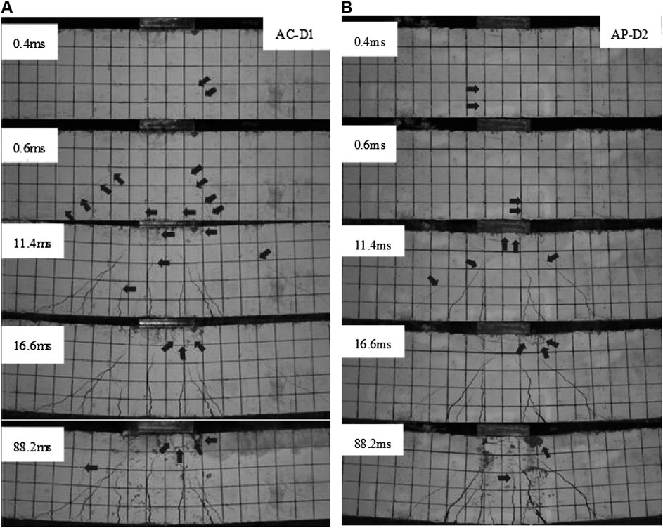
FIGURE 5. Crack propagation. (A) AC-D1, (B) AP-D2.
Failure Patterns of End-Anchorage-Fiber-Reinforced Polymer System
Intermediate crack (IC) debonding of FRP occurred for all specimens. For statically loaded specimens with PEN-FRP strengthening, the IC debonding initiated at 150 mm off the mid-span and propagated toward the ends of FRP laminate gradually. As shown in Figure 6A, the FRP debonding finally caused half of the FRP laminate to depart from the soffit of specimen EP-S, and the strengthening system failed consequently. For specimen AP-S, the debonded FRP laminate was held by the end-anchorages, and thus the EA-FRP system still worked even when the specimen underwent large deformation. For static loaded specimen AC-S, the IC debonding started at 100 mm off the mid-span, and the final failure pattern was the FRP rupture at the connection front left due to stress concentration (Figure 6B).
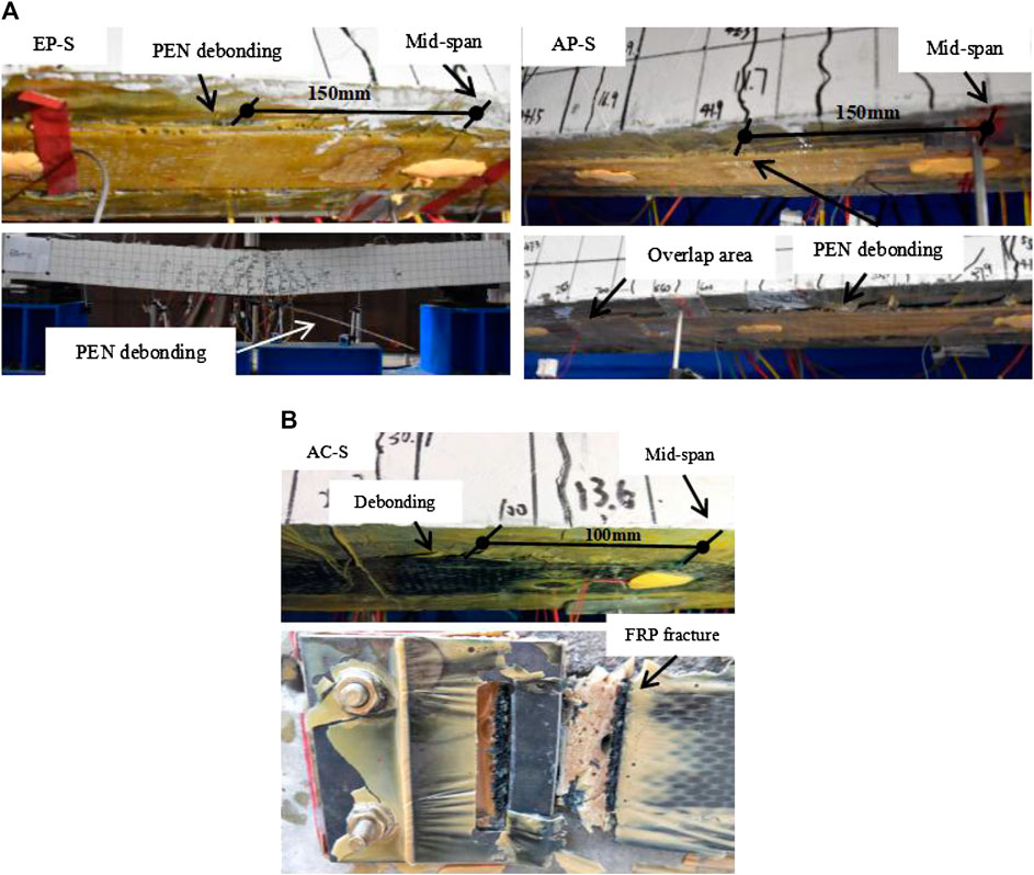
FIGURE 6. FRP debonding failure patterns in static tests. (A) FRP debonding process of EP-S and AP-S. (B) FRP debonding process of AC-S.
The failure patterns of specimens under impact showed significant differences with those of static specimens. Under impact loading, the FRP-concrete interface failed completely in an extremely short duration, and the tension force in the FRP laminate transferred to the end-anchorage with a very high loading rate. The strong dynamic effect induced intense stress concentration at the end-anchorage position. Figures 7A,C show that under the same impact condition (m = 516 kg, v = 4.6 m/s), the specimens strengthened by CFRP and PEN-FRP presented different failure modes of the EA-FRP system. For the PEN-FRP strengthened specimen (AP-D1), the FRP laminate debonded along the beam length but the end-anchorage was kept intact. However, for the CFRP strengthened specimen (AC-D1), although the end-anchorages had been reinforced by additional metallic fasteners, failure of the end-anchorage occurred. As shown in Figure 7C, the bolts of the metallic fasteners and the end-anchorage all presented loosening, and some bolts were even pulled out of the concrete matrix. For specimen AP-D2, the failure pattern of EA-FRP system was also controlled by the loosening of the bolts at the end-anchorage area, but the damage was less severe than that of AC-D1.
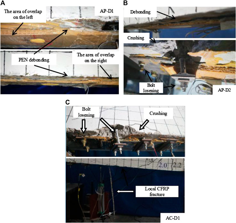
FIGURE 7. FPR debonding failure patterns in drop-weight tests. (A) AP-D1, (B)AP-D2, (C) AC-D1.
Figure 8 shows the detailed failure process of the EA-FRP system of specimen AC-D1 recorded by high-speed camera. The black arrows vertical downward are used to mark the observed FRP debonding location. It can be seen that the FRP debonding under impact initiated near the mid-span, where the flexural-shear cracks at the plastic zone cut through the bottom of the beam. With the beam moving downward, the FRP debonding area extended toward the mid-span and the support. At 16 ms, an inclined crack emerged at the location of the end-anchorage. At 20 ms, the bolts at the anchorage zone were pulled outward obviously, indicating the failure of the EA-FRP strengthening system. Meanwhile, it was observed that a part of the FRP laminate had already ruptured at the mid-span.
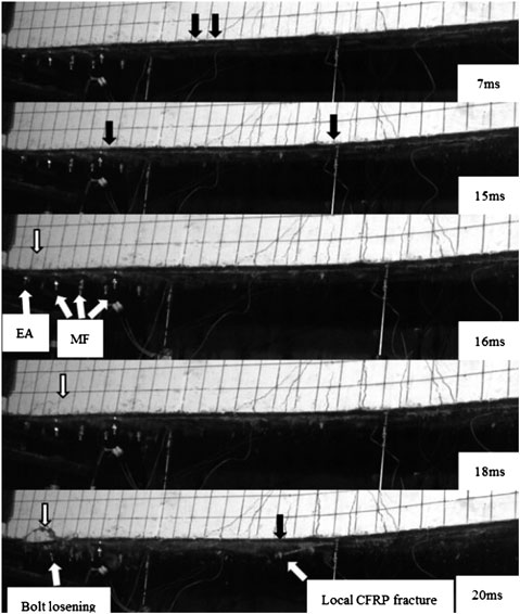
FIGURE 8. Failure process of EA-FRP systems at impact loading (AC-D1).
Static Performance
The mid-span load–deflection curves obtained from static tests are illustrated in Figure 9A. The load–deflection curves for all four specimens were consistent before the yielding load of specimen C-S (40.8 kN). At this stage, the behavior of the beam was approximately linear-elastic, and the FRP strengthening system had a slight contribution. After the yielding point, the load–deflection curve for specimen C-S became flat, indicating the loss of flexural stiffness due to the formation of plastic hinge after rebar yielding. The post-yield stiffness of EP-S was close to that of specimen C-S because the elastic modulus of PEN-FRP was small and its contribution to the beam stiffness was insignificant. When the peak load was reached, debonding of FRP occurred for specimen EP-S, and the resistance of the strengthened beam dropped to the same level with the control beam. For specimen AP-S, the presence of end-anchorage inhibited the slip at the FRP-concrete interface, and the post-yield stiffness of specimen AP-S was greater than specimen EP-S. Moreover, the end-anchorages hold the FRP laminate after it was completely debonded, so the sudden drop of resistance as specimen EP-S was not observed. The end-anchorages continued to provide tension force to the FRP strengthening system, and the load–deflection curve showed a prolonged plateau until the compressive concrete crushing. The modulus of CFRP laminate was larger than that of PEN-FRP, so specimen AC-S had a higher post-yield stiffness than AP-S. However, due to the brittleness of CFRP, the failure of specimen AC-S was controlled by FRP rupture at the FRP-concrete connection, and the ductility was much less than that of AP-S. Not all layers of the CFRP laminate fractured simultaneously, so the FRP rupture-induced load–deflection curve of specimen AC-S plummeted twice.
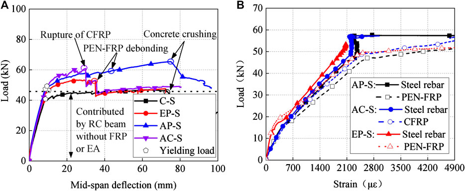
FIGURE 9. Static performance of specimens. (A) Load–deflection relationship, (B) load–strain relationship.
The resistance and mid-span deflection at concrete cracking, tensile steel rebar yielding, and peak load of all specimens are summarized in Table 4. The yielding loads of FRP strengthened beams were greater than that of control beams because the action of FRP slowed down the strain growth in reinforcement. The load–strain behaviors of steel bars and FRP laminates at mid-span section are plotted in Figure 9B. It can be seen that the load–strain relationship between steel rebar and FRP was consistent before concrete cracking, but the strain growth of FRP after concrete cracking was greater than that of steel rebar, which can be explained by the tensile stiffening of rebar in concrete (Belarbi and Hsu, 1994). All three strengthening methods can enhance the ultimate strength of RC beams significantly, but only specimen AP-S presented the best ductility similar to that of specimen C-S, whereas the ductility factors of EP-S and AC-S were only 41.4% and 39.0% of the control beam, respectively. Therefore, the PEN-FRP laminate with end-anchorage is an appropriate strengthening system that can enhance the bearing capacity while maintaining the deformation capability of the original structure.
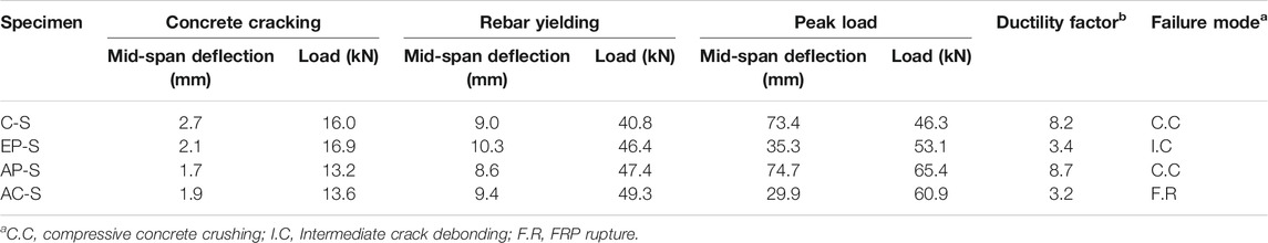
TABLE 4. Characteristic values of static tests.
Dynamic Performance Under Impact
Mid-Span Deflection and Fiber-Reinforced Polymer Strain Histories
The mid-span displacement histories and FRP strain histories of the impact specimens are illustrated in Figure 10, and characteristic values such as peak mid-span deflection, residual mid-span deflection, and the mid-span FRP strain at peak deflection are compared in Figure 11. Among the dynamically loaded specimens, specimen AP-D1 had the smallest peak deflection (58.3 mm) and residual deflection (40 mm), indicating the damage of the beam was slightest (Figure 11A). That is because the EA-FRP system of specimen AP-D1 kept functioning during the whole impact process, and the cooperative work of the EA-FRP system and the RC beam enabled complete utilization of the deformation capacity of PEN-FRP and reduced the damage to RC beam body. By contrast, Figure 10B show that an obvious strain drop occurred in the FRP laminate before the peak deflection, which was caused by the pulling out of the end anchors during the impact process. The failure of the end-anchorage-induced deformation of the specimen cannot be restrained by the EA-FRP system during the deformation process and undermined the strengthening effect to the impact resistance. The effectiveness of PEN-FRP in improving the impact resistance of beams strengthened by EA-FRP system can be demonstrated by comparing the mid-span deflection of specimens AP-D1 and AC-D1. As shown in Figure 11A, the deflection of AP-D1 is 23.9% smaller than that of AC-D1, indicating that PEN-FRP has more advantages in impact strengthening than CFRP.
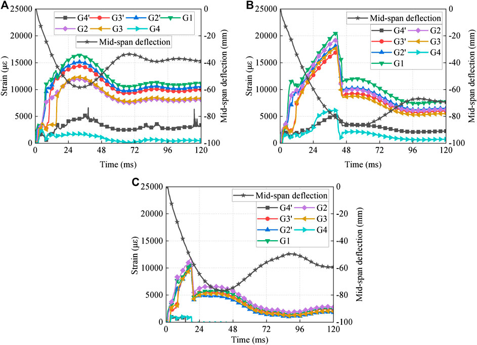
FIGURE 10. Mid-span deflection and FRP strain histories. (A) AP-D1, (B) AP-D2, (C) AC-D1.
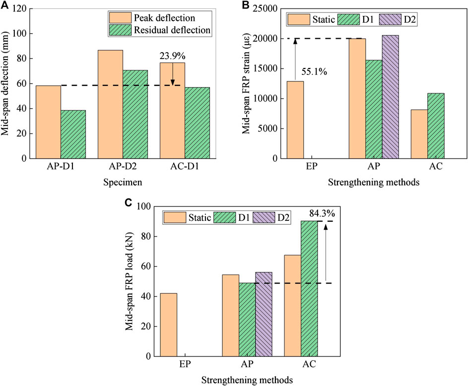
FIGURE 11. Mid-span deflection and FRP strain analysis. (A) Maximum and residual mid-span deflections, (B) maximum mid-span FRP strain, (C) maximum tensile force in FRP laminate at mid-span.
The maximum FRP strains in the mid-span of all specimens are summarized in Figure 11B. The maximum mid-span strain of specimen EP-S is only 12,875 με, whereas the maximum mid-span strain of specimen AP-S under ultimate load is 19,776 με, which is 55.1% higher than specimen EP-S. Therefore, the end-anchorage can increase the utilization efficiency of the PEN-FRP laminate. The maximum mid-span FRP strain of AP-S and AP-D2 was quite close, but the impact specimen AP-D2 presented severe end-anchorage failure, indicating that the end-anchorage was more susceptible to damage and failure when the loading rate increased from static to impact. For impact specimens, specimen AP-D2 underwent larger deformation than AP-D1, and thus larger tension strain was motivated in the FRP laminate of specimen AP-D2, which finally induced the failure of one of the end-anchorages. Besides, the maximum mid-span FRP strain of AC-D1 was much lower than that of AP-D1, and the cross-sectional area of CFRP laminate was also much smaller than that of PEN-FRP laminate. However, as shown in Figure 11C, due to the high elastic modulus of CFRP material, the tensile force of the CFRP laminate was 84.3% larger than that of AP-D1, which induced the end-anchorage failure of AC-D1. In addition, the comparison between specimens AC-S and AC-D1 shows that the maximum mid-span FRP strain of AC strengthened beam increased significantly under impact while the FRP at the connection did not rupture, demonstrating the effectiveness of the mechanical fasteners on avoiding stress concentration and FRP fracture at the connection between FRP and end anchors.
Fiber-Reinforced Polymer Strain Distribution
The PEN-FRP strain distributions at different deflection for all strengthened specimens are illustrated in Figure 12, where the x-axis starts from the mid-span, and the positive direction is toward the right support. The strain distributions in Figure 12A correspond to three deflection levels (dcr, dy, and du), which indicates the static deflections of concrete cracking, tensile steel bar yielding, and peak load, respectively. The PEN-FRP strain reached its maximum value in the mid-span and decreased toward the ends of FRP laminate. When the peak load was reached, the PEN-FRP strain of the right span significantly increased and the distribution curve at the right half-span was relatively flat. This indicates that the PEN had already been debonded from concrete cover.
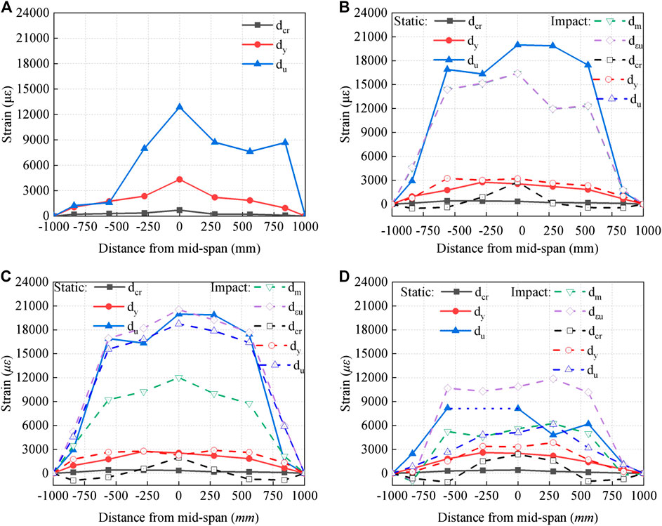
FIGURE 12. FRP strain distribution. (A) EP-S, (B) AP-D1 and AP-S, (C) AP-D2 and AP-S, (D) AC-D1 and AC-S.
To analyze the characteristics of FRP strain distribution under static load and impact load, FRP strain distributions of dynamic-loaded specimens at different characteristic states are illustrated in Figures 12B–D. The FRP strain distributions of the dynamic-loaded specimen and its static-loaded counterpart are compared at static deflection levels of dcr, dy, and du. Note that the mid-span deflection of specimen AP-D1 did not reach the static ultimate deflection du as AP-S, so the strain distribution of du is not given in Figure 12B. Moreover, for dynamic-loaded specimens, PEN-FRP strain distributions at the maximum deflection dm and the peak strain deflection dεn are also plotted in Figures 12B–D, respectively. Because the EA-FRP system of specimen AP-D1 kept functioning during the whole impact process, the FRP strain distribution curves of dm and dεn are consistent. However, for specimen AP-D2 and AC-D1 is reached dm, stress relaxation occurred in the FRP laminate due to the failure of the end-anchorage, thus the strain distribution curve of dm is generally lower than that of dεn.
The dynamic characteristics of FRP strain distributions under impact can be identified by comparing the FRP strain distributions of static and impact specimens at dcr, dy, and du. For static specimen, FRP strain at dcr was very small and the FRP was hardly stretched. However, for dynamic loaded specimens, the FRP strain at dcr was developed obviously and mainly concentrated at the mid-span, whereas at the quarter span, the FRP strain even became negative (compressive). The differences between the FRP strain distribution of static and impact specimens at dcr are caused by the shear wave propagating in the beam at the initial stage of impact (Saatci and Vecchio, 2009; Zhao et al., 2017). During the process of the deflection increasing from dcr to dy, the mid-span deflection strain under impact increased little and the FRP strain increased mainly at the shear span. By contrast, for the static specimens, the FRP strain along the span grew uniformly at the dcr-dy stage. When the deflection increased to du, the FRP strain distributions under static load and impact load were consistent overall.
Recorded Impact and Reaction Forces
The recorded impact and reaction force histories had similar characteristics as those described by previous researchers (Zhao et al., 2017; Liu et al., 2020). The impact force history consisted of two half-sine waves: an accessory wave with an extremely short duration and a large peak at the beginning of impact, and a main wave with a long duration and a small peak. By contrast, the reaction force history was a single half-sine wave with a small peak. Figure 13A shows the impact histories curves of all impact specimens. The specimens with greater maximum mid-span deflection had relatively smaller maximum impact peaks, and the duration of the main wave was longer. As shown in Figure 13B, the reaction force oscillated several times before stabilizing at a positive value, and the oscillation may cause negative values of reaction force. The reaction force histories differed little except for the different duration, which was consistent with the histories of the impact force.
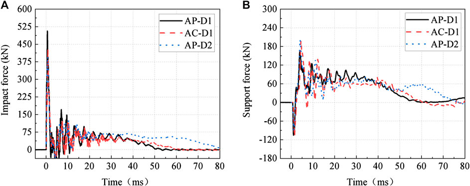
FIGURE 13. Impact force and reaction force histories. (A) Impact force histories, (B) reaction force histories.
An obvious time lag between the impact force and the reaction forces was observed, which indicates the influence of stress wave propagation. The time delay for three dynamically loaded specimens varied from 0.67 to 0.79 m with an average of 0.71 ms, as shown in Figure 14. Furthermore, the propagation velocity of stress wave in concrete can be calculated by dividing the length of half span by the time difference. The calculated value 1,753 m/s is slightly less than the theoretical transverse wave velocity within concrete medium 2,400 m/s. The possible reason is that the stress wave took longer time to propagate in the concrete due to the accumulation of damage during the impact process, which reduced the propagation velocity. However, due to the limited number of specimens and low impact velocity in the test, the conclusion of stress wave propagation still needs to be verified by more experimental and theoretical studies.
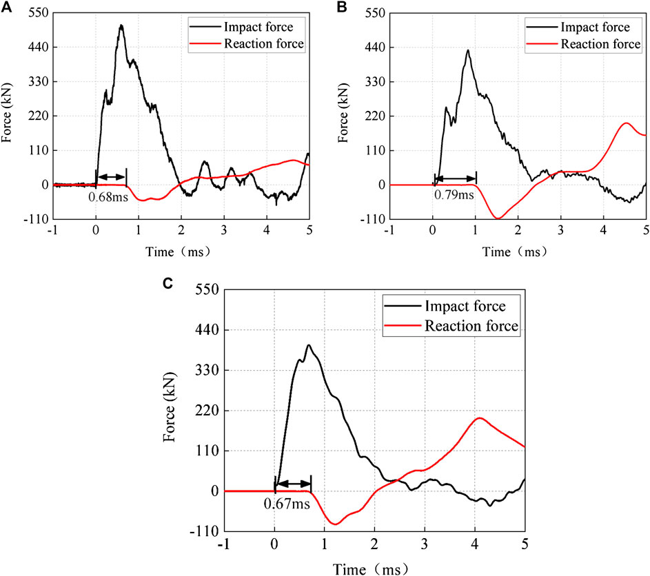
FIGURE 14. Time delay between reaction force and impact. (A) AP-D1, (B) AC-D1, (C) AP-D2.
Conclusions
In this study, static tests and drop-weight tests of PEN-FRP and CFRP strengthened RC beams were conducted, and the influences of FRP types, loading rate, and end-anchorages on the static and dynamic performances of strengthened beams were investigated. Static and dynamic response characteristics and failure mechanisms of the strengthened beams were analyzed and discussed based on the experimental data. The following conclusions can be drawn:
(1) Compared with externally bonded PEN-FRP and end-anchorage CFRP strengthening methods, the PEN-FRP laminate with end-anchorage is proven to be an appropriate strengthening technique that can enhance the bearing capacity while maintaining the deformation capability of the original RC beam. Under impact loading, the end-anchorage PEN-FRP strengthening system can also reduce the maximum deflection and damage of strengthened beam significantly.
(2) Under static loading, the failure of CFRP strengthened beam was caused by FRP rupture at the connection between CFRP and end-anchorage, whereas PEN-FRP was not cut off due to its small elastic modulus and large rupture strain properties. The application of mechanical fasteners at the overlap area can effectively prevent stress concentration at the CFRP end-anchorage connection, thereby preventing the CFRP rupture failure at this zone.
(3) When the mid-span deflection is small (d = dcr), the FRP strain distributions of specimens under static and impact loading were apparently different. Under static loading, the FRP is hardly stretched at dcr and the FRP strain is very small. However, under impact loading, the FRP strain was obvious and concentrated at the mid-span, whereas at quarter span, the FRP strain even became negative. The differences of FRP strain distribution between static and impact loading specimens were caused by the stress wave propagation at the initial stage of impact.
(4) The end-anchorage was more susceptible to damage and failure when the loading rate increased from static to impact. Therefore, the end-anchorage and the EA-FRP connection should be designed with caution for impact condition.
Data Availability Statement
The raw data supporting the conclusions of this article will be made available by the authors, without undue reservation.
Author Contributions
ZY and DZ preformed the experiments. ZY, DZ, and ZH wrote the article. LS, HZ, and XZ reviewed and edited the article. All authors contributed to the article and approved the submitted version.
Funding
The work described in this article was financially supported by the National Natural Science Foundation of China (Grants No. 51808345). The authors are grateful for each one of these contributions.
Conflict of Interest
The authors declare that the research was conducted in the absence of any commercial or financial relationships that could be construed as a potential conflict of interest.
Appendix
In this paper, the data and failure modes recorded in static and impact tests are summarized in Table A1
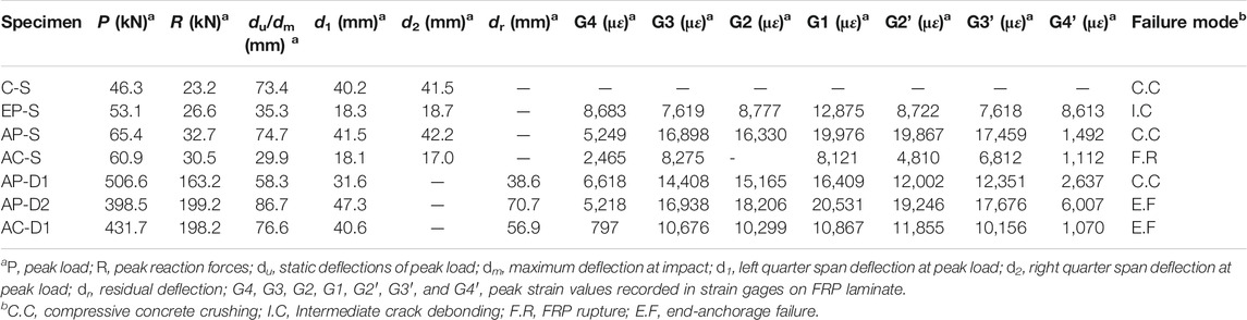
TABLE A1. Key data recorded during the test.
References
ACI 440.2R-17 (2017). Guide for the design and construction of externally bonded FRP systems for strengthening concrete structures, ACI Committee 440. Farmington Hills, MI: American Concrete Institute.
Anggawidjaja, D., Ueda, T., Dai, J., and Nakai, H. (2006). Deformation capacity of RC piers wrapped by new fiber-reinforced polymer with large fracture strain. Cement Concr. Compos. 28, 914–927. doi:10.1016/j.cemconcomp.2006.07.011
ASTM C39/39M (2005). Standard test method for compressive strength of cylindrical concrete specimens. West Conshohocken, PA: ASTM International.
ASTM D3039-18 (2017). Standard test method for tensile properties of polymer matrix composite materials. West Conshohocken, PA: ASTM International.
ASTM E8/E8M-11 (2011). Standard test methods for tension testing of metallic materials. West Conshohocken, PA: American Standards and Testing, ASTM International.
Baasankhuu, B., Choi, D., and Ha, S. (2020). Behavior of small-scale concrete cylinders in compression laterally confined by basalt fiber and PEN fiber reinforced polymer composites. Int. J. Concr. Struct. Mater. 14. doi:10.1186/s40069-019-0384-6
Bai, Y.-L., Yan, Z.-W., Ozbakkaloglu, T., Dai, J.-G., Jia, J.-F., Jia, J.-B., et al. (2019). Dynamic behavior of PET FRP and its preliminary application in impact strengthening of concrete columns, Appl. Sci. 9, 4987. doi:10.3390/app9234987
Bai, Y.-L., Yan, Z.-W., Ozbakkaloglu, T., Han, Q., Dai, J.-G., and Zhu, D.-J. (2020). Quasi-static and dynamic tensile properties of large-rupture-strain (LRS) polyethylene terephthalate fiber bundle. Construct. Build. Mater. 232, 117241. doi:10.1016/j.conbuildmat.2019.117241
Baji, H., Ronagh, H. R., and Li, C.-Q. (2016). Probabilistic assessment of FRP-confined reinforced concrete columns. Compos. Struct. 153, 851–865. doi:10.1016/j.compstruct.2016.07.003
Belarbi, A., and Hsu, T. (1994). Constitutive laws of concrete in tension and reinforcing bars stiffened by concrete. ACI Struct. J. 91, 465–474.
Bencardino, F., Colotti, V., Spadea, G., and Swamy, R. N. (2005). Shear behavior of reinforced concrete beams strengthened in flexure with bonded carbon fibre reinforced polymers laminates. Can. J. Civ. Eng. 32, 812. doi:10.1139/L05-027
Bencardino, F., Colotti, V., Spadea, G., and Swamy, R. N. (2006). Holistic design of RC beams and slabs strengthened with externally bonded FRP laminates. Cement Concr. Compos. 28, 832. doi:10.1016/j.cemconcomp.2006.07.015
Benzeguir, Z., El-Saikaly, G., and Chaallal, O. (2020). Size effect of RC T-beams strengthened in shear with externally bonded CFRP L-shaped laminates. J. Compos. Construct. 24. doi:10.1061/(ASCE)CC.1943-5614.0001045
CAN/CSA S806-12 (2017). Design and construction of building components with fiber-reinforced polymers. Mississauga, Ontario, Canada: Canadian Standards Association.
CECS (2003). Technical specification for strengthening concrete structures with carbon fiber reinforcea polymer laminate. Beijing, China: China Engineering Construction Standardization Association, 146:2003
Chen, W., Pham, T. M., Sichembe, H., Chen, L., and Hao, H. (2018). Experimental study of flexural behaviour of RC beams strengthened by longitudinal and U-shaped basalt FRP sheet. Compos. B Eng 134, 114. doi:10.1016/j.compositesb.2017.09.053
Chen, C., Yang, Y., Yu, J., Yu, J., Tan, H., Sui, L., et al. (2020). Eco-friendly and mechanically reliable alternative to synthetic FRP in externally bonded strengthening of RC beams: Natural FRP. Compos. Struct. 241, 112081. doi:10.1016/j.compstruct.2020.112081
CNR-DT 200 R1/2013 (2013). Guide for the design and construction of externally bonded FRP systems for strengthening existing structures, National Research Council, Rome.
Dai, J.-G., Bai, Y.-L., and Teng, J. G. (2011). Behavior and modeling of concrete confined with FRP composites of large deformability. J. Compos. Construct. 15, 963–973. doi:10.1061/(ASCE)CC.1943-5614.0000230
Dai, J.-G., Yokota, H., and Ueda, T. (2009). A hybrid bonding system for improving the structural performance of FRP flexurally strengthened concrete beams. Adv. Struct. Eng. 12, 821–832. doi:10.1260/136943309790327671
El Maaddawy, T., and Soudki, K. (2008). Strengthening of reinforced concrete slabs with mechanically-anchored unbonded FRP system. Construct. Build. Mater. 22, 444–455. doi:10.1016/j.conbuildmat.2007.07.022
Fujikake, K., Li, B., and Soeun, S. (2009). Impact response of reinforced concrete beam and its analytical evaluation. J. Struct. Eng. 135, 938–950. doi:10.1061/(ASCE)ST.1943-541X.0000039
GB 50367-2013 (2013). Code for design of strengthening concrete structures. Chinese National Standard, China’s Construction Industry.
GB 50608-2010 (2010). Technical code for infrastructure application of FRP composites. Beijing: Chinese National Standard.
Jirawattanasomkul, T., Dai, J., Zhang, D., Senda, M., and Ueda, T. (2014). Experimental study on shear behavior of reinforced-concrete members fully wrapped with large rupture-strain FRP composites. J. Compos. Construct.18. doi:10.1061/(ASCE)CC.1943-5614.0000442
Kalfat, R., and Al-Mahaidi, R. (2010). Investigation into bond behaviour of a new CFRP anchorage system for concrete utilising a mechanically strengthened substrate. Compos. Struct. 92, 2738–2746. doi:10.1016/j.compstruct.2010.04.004
Kalfat, R., Al-Mahaidi, R., and Smith, S. T. (2013). Anchorage devices used to improve the performance of reinforced concrete beams retrofitted with FRP composites: state-of-the-art review. J. Compos. Construct. 17, 14–33. doi:10.1061/(ASCE)CC.1943-5614.0000276
Li, W., Huang, Z., Huang, Z., Yang, X., Shi, T., and Xing, F. (2020). Shear behavior of RC beams with corroded stirrups strengthened using FRP laminates: effect of the shear span-to-depth ratio. J. Compos. Construct. 24. doi:10.1061/(ASCE)CC.1943-5614.0001042
Liu, T., Kang, T. H.-K., Nghiem, A., and Xiao, Y. (2020). Impact testing of reinforced concrete beams shear-strengthened with fiber-reinforced polymer wraps. ACI Struct. J. 117, 297–310. doi:10.14359/51723497
Liu, T., and Xiao, Y. (2017). Impact behavior of CFRP-strip-wrapped RC beams without stirrups. J. Compos. Construct. 21. doi:10.1061/(ASCE)CC.1943-5614.0000815
Liu, X., and Li, Y. (2018). Experimental study of seismic behavior of partially corrosion-damaged reinforced concrete columns strengthened with FRP composites with large deformability. Construct. Build. Mater. 191, 1071–1081. doi:10.1016/j.conbuildmat.2018.10.072
Nie, X. F., Fu, B., Teng, J. G., Bank, L. C., and Tian, Y. (2020). Shear behavior of reinforced concrete beams with GFRP needles. Construct. Build. Mater. 257, 119430. doi:10.1016/j.conbuildmat.2020.119430
Oller, E., Pujol, M., and Marí, A. (2019). Contribution of externally bonded FRP shear reinforcement to the shear strength of RC beams. Compos. B Eng 164, 235. doi:10.1016/j.compositesb.2018.11.065
Pham, T., and Hao, H. (2016). Impact behavior of FRP-strengthened RC beams without stirrups. J. Compos. Construct. 20. doi:10.1061/(ASCE)CC.1943-5614.0000671
Pham, T. M., and Hao, H. (2017). Behavior of fiber-reinforced polymer-strengthened reinforced concrete beams under static and impact loads. International Journal of Protective Structures 8, 3–24. doi:10.1177/2041419616658730
Saatci, S., and Vecchio, F. J (2009). Effects of shear mechanisms on impact behavior of reinforced concrete beams. ACI Struct. J. 106, 78–86.
Saleem, S., Hussain, Q., and Pimanmas, A. (2017). Compressive behavior of PET FRP-confined circular, square, and rectangular concrete columns. J. Compos. Construct. 21. doi:10.1061/(ASCE)CC.1943-5614.0000754
Sayed, A. (2020). Experimental study of large-scale RC beams shear-strengthened with basalt FRP sheets. Civ. Eng. J. 6. doi:0.28991/cej-2020-0309150710.28991/cej-2020-03091507
Teng, J., Chen, J., Smith, S., and Lam, L. (2002). FRP: strengthened RC structures. Front. Physiol 266.
Teng, J. G., Yu, T., and Fernando, D. (2012). Strengthening of steel structures with fiber-reinforced polymer composites. J. Constr. Steel Res. 78, 131. doi:10.1016/j.jcsr.2012.06.011
Yu, T., Zhang, S., Huang, L., and Chan, C. (2017). Compressive behavior of hybrid double-skin tubular columns with a large rupture strain FRP tube. Compos. Struct. 171, 10–18. doi:10.1016/j.compstruct.2017.03.013
Zhang, H. W., and Smith, S. T. (2012). Influence of FRP anchor fan configuration and dowel angle on anchoring FRP plates. Compos. B Eng. 43, 3516–3527. doi:10.1016/j.compositesb.2011.11.072
Zhang, H., and Smith, S. T. (2017). Influence of plate length and anchor position on FRP-to-concrete joints anchored with FRP anchors. Compos. Struct. 159, 615–624. doi:10.1016/j.compstruct.2016.09.086
Zhao, D., Yi, W., and Kunnath, S. (2017). Shear mechanisms in reinforced concrete beams under impact loading. J. Struct. Eng 143. doi:10.1061/(ASCE)ST.1943-541X.0001818
Zhou, Y., Chen, X., Fan, Z., Sui, L., Li, D., and Xing, F. (2017). Bond behaviors of FRP-to-concrete interface under the control of a novel end-anchorage system. Compos. Struct. 168, 130. doi:10.1016/j.compstruct.2017.02.056
Zhao, Y. R., Yang, H. Q., Huang, L. P., Chen, R., Chen, X. S., and Liu, S. Y. (2019). Mechanical behavior of intact completely decomposed granite soils along multi-stage loading-unloading path. Eng. Geol. 260, 105242. doi:10.1016/j.enggeo.2019.105242
Zhou, Y., Wang, X., Sui, L., Xing, F., Wu, Y., and Chen, C. (2018). Flexural performance of FRP-plated RC beams using H-type end anchorage. Compos. Struct. 206, 11. doi:10.1016/j.compstruct.2018.08.015
Zhou, Y., Zhang, J., Li, W., Hu, B., and Huang, X. (2020a). Reliability-based design analysis of FRP shear strengthened reinforced concrete beams considering different FRP configurations. Compos. Struct. 237, 111957. doi:10.1016/j.compstruct.2020.111957
Keywords: dynamic response, large-rupture-strain fiber-reinforced polymer, drop-weight test, impact loading, strengthened reinforced concrete beam
Citation: Ye Z, Zhao D, Sui L, Huang Z and Zhou X (2020) Behaviors of Large-Rupture-Strain Fiber-Reinforced Polymer Strengthened Reinforced Concrete Beams Under Static and Impact Loads. Front. Mater. 7:578749. doi:10.3389/fmats.2020.578749
Received: 01 July 2020; Accepted: 23 September 2020;
Published: 05 November 2020.
Edited by:
Roberto Realfonzo, University of Salerno, ItalyReviewed by:
Tommaso D’Antino, Politecnico di Milano, ItalyFrancesco Bencardino, University of Calabria, Italy
Copyright © 2020 Ye, Zhao, Sui, Huang and Zhou. This is an open-access article distributed under the terms of the Creative Commons Attribution License (CC BY). The use, distribution or reproduction in other forums is permitted, provided the original author(s) and the copyright owner(s) are credited and that the original publication in this journal is cited, in accordance with accepted academic practice. No use, distribution or reproduction is permitted which does not comply with these terms.
*Correspondence: Debo Zhao, debozhao@163.com