

Abstract
This study presents a bone conduction microphone (BCM) to detect the variation of air pressure resulted from the skull vibration. The presented BCM consists of a commercial MEMS microphone, the sensing circuits, the bulk metal, the deformable polymer diaphragm, and two printed circuit board (PCB) covers. In this design, two chambers and a vibrating spring-mass structure are hermetic sealed by two PCB covers. As the spring-mass structure vibrates, the pressure of one chamber will increase and that of another will decrease. Thus, the vibration could introduce a higher pressure load as well as a larger sensing signal for the BCM. In application, the device with the dimensions of 3.5 × 2.65 × 1.48 mm3 is implemented. Measurements show the device has a sensitivity of −38.8 dBV, THD < 0.48% at 1 kHz with 1 g excitation, and ±5 dB bandwidth for 100 Hz∼6.7 kHz. Frequency responses of different samples show good repeatability. Furthermore, air leakage effect and crosstalk of the skull vibration sensing module have also been investigated in this paper. The results demonstrate the feasibility of the presented BCM.
Export citation and abstract BibTeX RIS
1. Introduction
Presently, the voice recognition becomes a convenient and important approach for the communication interface of human and machine, and has found many applications in the consumer electronics such as the smart phone, home robots, headset, and so on. Moreover, the communication and interaction with the virtual assistant can be achieved with the existing of voice recognition. Thus, the applications and requirements of MEMS microphone are continuously growing, and many different MEMS acoustic microphones have been reported and commercialized [1–9] to date. As shown in figure 1(a), the sound port is required for packaged MEMS acoustic microphones to transmit the sound pressure. Therefore, the dust and water proof are needed for such MEMS microphone [10]. The dust and water issues have been solved by sound port with polymer mesh [11]. Moreover, in addition to the target signal, the environment noise and wind will also transmit through the sound port, which is a concern for the application of voice recognition [12]. For example, the wind through sound port brings pressure fluctuation on the MEMS diaphragm and further degrades the accuracy of voice recognition. Noise suppression and beamforming algorithms [13–16] are generally applied in communication devices with acoustic microphones to improve call quality. However, it remains challenging to improve the voice signal in extremely noisy environment with poor signal-to-noise ratio. The digital signal processing is a common solution to identify and analyze the voice from users. In this regard, the digital signal processor (DSP) needs to be always on so that the power consumption becomes a critical issue, especially for portable devices.
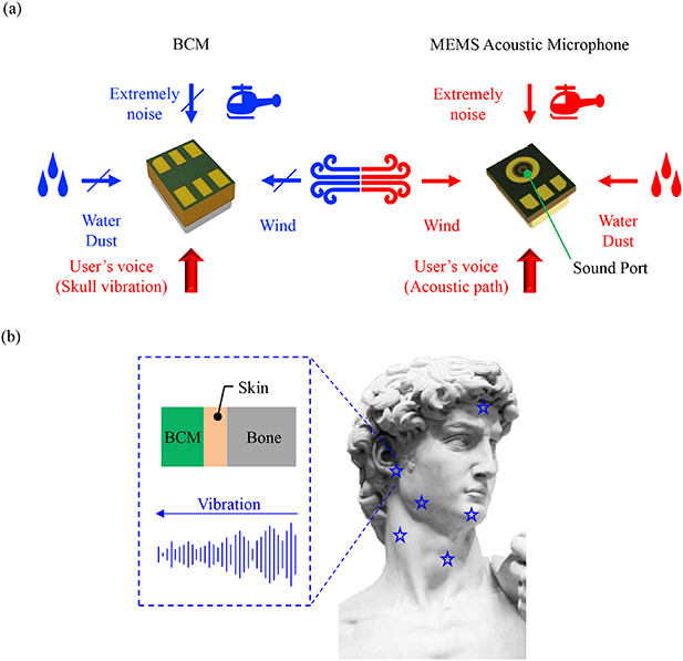
Figure 1. (a) Comparison of BCM and conventional microphone, and (b) arrangement of the BCM for voice detection.
Download figure:
Standard image High-resolution imageThe vocal folds vibration will introduce the airflow to generate the sound pressure and voice. Thus, in addition to the acoustic microphone, the voice can also be detected by the skull (vocal folds) vibration. The bone conduction microphone (BCM) has been achieved by detecting the skull vibration [17, 18]. The commercial product [19] implements the bone conduction principle through the accelerometer to improve the low frequency sound and active noise control. Since no sound port is required on the packaged caps, the BCM is reliable and could operate in harsh environment, such as the environment with water, dust, wind, and noise. Therefore, the BCM can be applied in not only the consumer electronics but also the military communication system. Although the MEMS accelerometer has been exploited to detect the bone vibration, its bandwidth is not enough for microphone applications [20]. The pressure generating and sensing module in [19] for vibration detection could increase the sensing bandwidth compared to accelerometers. The approach and algorithm to combine sensing signals received from the acoustic microphone and skull vibration sensor has been adopted in [21, 22] to enhance the communication quality. Moreover, the skull vibration sensor can be adopted to act as a 'switch' to turn on the function of DSP. Thus, the DSP will only be operated when existing the voice or skull vibration, and the power consumption of DSP for voice recognition can be reduced.
As shown in figure 1(b), the BCM could be mounted in various positions to detect the skull vibration. However, the excitation from skull vibration could be decayed after transmitting through the skin. To enhance the sensitivity of BCM could benefit the related applications. The existing BCM microphone [19] has a reference chamber with fixed pressure, and another chamber having its volume and pressure varying with a vibrating structure. The vibration induced time-dependent pressure change can be detected by the traditional microphone embedded in the BCM. This study extends the design in [23] to present the BCM design to enhance the sensitivity of the BCM. In this design, two chambers and a vibrating spring-mass structure are hermetic sealed by two covers. As the spring-mass structure vibrates, one chamber pressure will increase and another will decrease. Thus, the pressure difference between two chambers could introduce a higher pressure load on an embedded MEMS sensor and further yield a larger sensing signal for the BCM. Simulations show the feasibility of the design. To demonstrate the present concept, the BCM is realized by using the bonding and assembly of a commercial MEMS microphone and sensing circuits with the polymer diaphragm and bulk metal. Since the required components are ready on the shelf, the implementation and mass production of the proposed BCM can be easily achieved. To demonstrate the advantages of the proposed design, this study also performs tests to compare the presented BCM with the conventional MEMS accelerometer and acoustic microphone.
2. Design concepts and principles
This study presents a packaged MEMS sensing module shown in figure 2 to detect the time-dependent air pressure variation resulted from the skull vibration, and hence the BCM can be achieved. The left schematic illustration of figure 2(a) depicts the packaged MEMS sensing module for the presented BCM. As shown in the right illustration of figure 2(a), the MEMS sensor, ASIC (application specific integrated circuit), and their electrical routings are observed after removing the top cover of BCM. Since the cover has no opening for sound port, the MEMS sensor and ASIC are isolated with ambient after packaging. As compare with the MEMS acoustic microphone, the presented BCM design could prevent the penetration and influence of wind and environment noise. Moreover, without the sound port, the damage of suspended MEMS structures by dust and water can also be avoided. Figure 2(b) displays the AA' cross section of presented BCM and its working principle. The top schematic illustration in figure 2(b) indicates the whole presented BCM consisting of the MEMS sensor, the ASIC, the bulk metal (1.8 mm in length, 1.3 mm in width, and 0.3 mm in thickness), the deformable polymer diaphragm, and two printed circuit board (PCB) covers (top and bottom covers). The polymer diaphragm is attached to and also supported by the top and bottom PCB covers. The MEMS sensor and its ASIC are mounted and wire bonded on the top side of the polymer diaphragm. As shown in figure 2(c), the electrical routings and bonding pads are patterned on the polymer diaphragm. Moreover, the bulk metal is attached to the back side of the polymer diaphragm. Thus, an equivalent spring-mass system is established by the polymer diaphragm, MEMS and ASIC chips, and the bulk metal. In short, the flexible polymer diaphragm acts as the spring and the rigid bulk metal together with the MEMS and ASIC chips act as the proof-mass. The bulk metal also acts as a rigid carrier to support the MEMS sensing chip, the ASIC, and the bonded wires. After that, the chamber hermetic sealed by two PCB covers is partitioned by the polymer diaphragm and MEMS sensor into the Chamber-I and Chamber-II, as indicated in figure. Note that the holes on diaphragm and bulk metal are designed to enable the deformable structure on MEMS sensor exposed to both chambers. The bottom schematic drawing in figure 2(b) exhibits the operation principle of the presented BCM. As the skull vibration propagating to the BCM, the equivalent spring-mass system formed by the diaphragm, bulk metal, and sensing chips will vibrate. The vibration of equivalent spring-mass will cause time-dependent volume as well as pressure variations of hermetic sealed chambers (Chamber-I and Chamber-II), and further introduce a time-dependent pressure load ΔP(t) (ΔP(t) = P1(t)−P2(t), as indicated in figure) on the MEMS sensor. Therefore, the skull vibration can be detected by measuring the time-dependent pressure load ΔP(t) using the embedded MEMS sensor. In short, the pressure in Chamber-I can be expressed as,

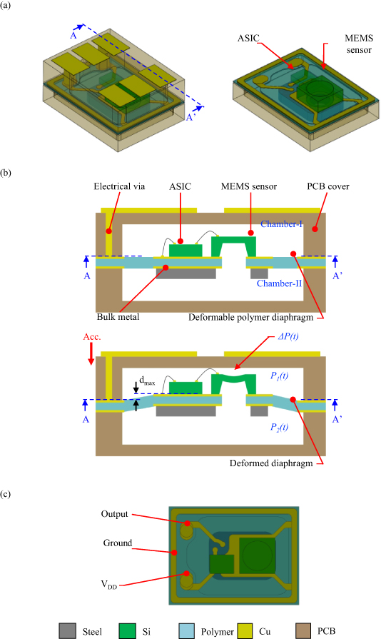
Figure 2. (a) Schematic design of the presented BCM before and after removing the top cover, (b) the AA' cross-section view of the presented BCM before and after the excitation from skull vibration, and (c) the electrical routings and bonding pads patterned on the polymer diaphragm.
Download figure:
Standard image High-resolution imagewhere P0 is the initial chamber pressure after sealing, and ΔP1(t) is varying with the volume change of Chamber-I, and meanwhile the pressure in Chamber-II can be expressed as,

similarly, ΔP2(t) is varying with the volume change of Chamber-II. Note that as the pressure in Chamber-I increases, the pressure in Chamber-II will decrease, and vice versa. Thus, the time-dependent pressure load ΔP(t) on the deformable MEMS structure becomes,

As Chamber-I and Chamber-II have approximate initial volume, the pressure variation of these two chambers becomes  , and the pressure load can be expressed as,

As compare with the design for pressure variation on only one chamber [17], the present BCM could increase the net pressure load on the deformable MEMS structure to increase the sensing signal. In addition, figure 3(a) further shows the relationship of pressure variation and diaphragm displacement in pressure field for the presented design. According to the lumped parameter method [24], the pressure variation (in Laplace domain) can be expressed as,


Figure 3. (a) The lumped model of the presented BCM in the acoustic domain, and (b) the presented BCM and its FEM simulation model (after removing the top PCB cover) where the air inside both chambers has also been meshed.
Download figure:
Standard image High-resolution imagewhere  is the equivalent radiation area,
  is the displacement of diaphragm center,
  is the compliance of Chamber-I, and
  is the compliance of Chamber-II. The compliances
  and
and  are given by,

where  is the air density,
  is the sound speed,
  is the volume of Chamber-I, and
  is the volume of Chamber-II. Thus, equation (5) can be rewritten as,

Thus, the pressure variation  with respect to the diaphragm displacement
  is determined from equation (7).
This study exploits the commercial finite element method (FEM) software (COMSOL) to predict the dynamic responses of the presented BCM when excited by the skull vibration. Moreover, the pressure changes of Chamber-I and Chamber-II are also investigated. The presented BCM and its FEM model with meshes are shown in figure 3(b). The model includes the equivalent spring-mass system formed by the polymer diaphragm, the MEMS chip with fully-clamped circular diaphragm, the ASIC chip, and the Cu electrical routings. In addition, the ambient air sealed in Chamber-I and II is also included in the FEM model. Various conditions are setting in the FEM model: (1) four edges of the rectangular polymer diaphragm are fully clamped; (2) the air inside sealed chambers has been meshed so that the air could act as a medium to transmit acoustic pressure; and (3) the harmonic excitation is applied on the FEM model to simulate the skull vibration. Figure 4 further summarizes various FEM simulation results. Simulation results in figure 4(a) display the frequency responses of the equivalent spring-mass system when driven at 1 g and 4 g excitation. The maximum displacements (dmax
shown in figure 2(b)) of equivalent spring-mass system at different frequencies are determined. The results show the first resonance frequency of the equivalent spring-mass system is at 9.5 kHz. Simulations also indicate that the bulk metal (MEMS chip as well) has a maximum deformation dmax
of near 1 μm with a 4 g excitation at the resonance frequency. In this design, the space between the bulk metal and bottom cover is larger than 200 μm, and the headroom between the MEMS sensor and top cover is also larger than 200 μm, no contact will occur between the spring-mass system and covers within the sensing range. Simulation results in figure 4(b) further depict the maximum pressure difference between Chamber-I and Chamber-II (i.e. the amplitude of pressure load ΔP(t) on MEMS sensor). As expressed in equations (1)–(3), the pressure difference between these two chambers is resulted from the displacement of equivalent spring-mass system. As the excitation is 1 g at 1 kHz, the maximum pressure difference between Chamber-I and Chamber-II is 1.16 Pa (Chamber-I and Chamber-II are respectively ±0.58 Pa and  0.58 Pa). Moreover, the maximum pressure difference between Chamber-I and Chamber-II becomes 4.64 Pa (Chamber-I and Chamber-II are respectively ±2.31 Pa and
  2.33 Pa) when the excitation is 4 g at 1 kHz. The time-dependent pressure difference between Chamber-I and Chamber-II will introduce ΔP(t) to cause the vibration of MEMS diaphragm, as shown in figure 4(c). Simulations demonstrate the concept to exploit the vibration excitation to introduce the time-dependent pressure load ΔP(t) and further lead the vibration of flexible diaphragm on MEMS chip. In comparison, the pressure load determined from the equation (7) is 1.14 Pa, and which is similar to the simulation result of 1.16 Pa. This study also investigates the influence of process and material tolerance through simulations by adding ±10% variations for the polymer diaphragm thickness and Young's modulus in the FEM model. Simulation results show the maximum pressure difference between chambers for 1 g excitation has an upper bond of 1.67 Pa (when both thickness and Young's modulus decreasing 10%) and a lower bond of 0.83 Pa (when both thickness and Young's modulus increasing 10%). Thus the sensitivity deviation may occur and will be corrected by the sensing circuits.
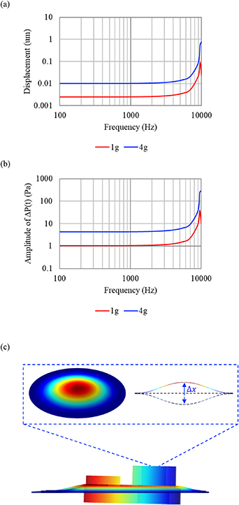
Figure 4. Typical simulation results to show (a) the frequency response (maximum displacement) within 100 Hz∼10 kHz for 1 g and 4 g, (b) the frequency response (the maximum pressure difference between two chambers, or the amplitude of pressure load ΔP(t) on the deformable MEMS structure) within 100 Hz∼10 kHz for 1 g and 4 g, and (c) the deformations of polymer and MEMS diaphragms and the displacements of sensing chips and bulk metal.
Download figure:
Standard image High-resolution imageThis study further investigates the air leakage behaviors when the pressure load ΔP(t) applying on the MEMS diaphragm with a circular opening of diameter D, as shown in figure 5(a). The circular port enables the air leakage between Chamber-I and Chamber-II and the diameter D is varying from 0 to 10 μm in the simulation models. Such simplified simulation model is to approximate the MEMS microphone chip containing a diaphragm with openings. Simulation results in figure 5(b) indicate the maximum pressure difference between Chamber-I and Chamber-II at different excitation frequencies. Since the acoustic impedance is considerably large when the diameter D is less than 6 μm, the amplitudes of pressure load ΔP(t) between 100 Hz–1 kHz remain flat. As D increases to 7 μm, the amplitude of pressure load ΔP(t) at 100 Hz drops to 0.89 Pa. Once D is larger than 7 μm, low frequency level is rolling-off dramatically and further narrowing the operation bandwidth. The simulation offers a design guideline while choosing the existing commercial MEMS microphone for the presented BCM. Finally, the crosstalks introduced by excitations in different directions are studied. As indicated in figure 6, the major excitation resulted from the skull vibration is Az . However, vibrations in two orthogonal directions Ax and Ay will also introduce pressure load on the presented BCM. Simulations in figure 6 show the amplitudes of pressure loads when respectively applying 1 g excitation in three different directions Ax, Ay , and Az on the simulation model. The amplitude of pressure load resulted from the Az excitation is 1.16 Pa at 1 kHz, whereas the amplitudes of pressure loads respectively dropped to 0.004 Pa and 0.038 Pa (at 1 kHz) for the excitations of Ax and Ay . Since the structure of equivalent spring-mass is not axisymmetric, crosstalks caused by the Ax and Ay excitations are different.
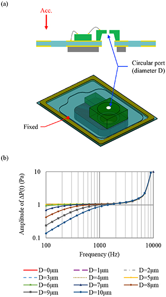
Figure 5. (a) Diaphragm (on MEMS chip) with circular port of diameter D, and (b) frequency responses (the amplitude of pressure load ΔP(t) on the deformable MEMS structure) for diaphragms with circular port of different diameter D.
Download figure:
Standard image High-resolution image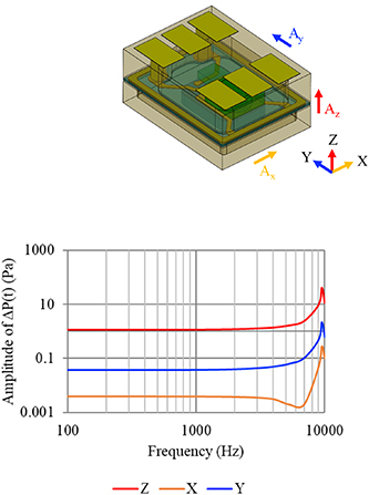
Figure 6. Simulations (crosstalk) of the frequency responses (the amplitude of pressure load ΔP(t) on the deformable MEMS structure) when applying 1 g excitation in three different directions Ax, Ay , and Az.
Download figure:
Standard image High-resolution image3. Fabrication and results
Figure 7 illustrates process steps to implement the proposed skull vibration sensing module. As shown in figure 7(a), the perforated polymer diaphragm with electrical routings was fabricated. After that, the MEMS sensor and its ASIC were respectively bonded on the polymer diaphragm, as shown in figure 7(b). The wire-bonding process between two chips and electrode routings on polymer diaphragm was then performed, as depicted in figure 7(c). After that, the top PCB cover with cavity, electrical vias, and bond pads were fabricated and then bonded to the polymer diaphragm, as indicated in figure 7(d). The PCB cover is employed to support the outer edge of diaphragm and seal the commercial MEMS microphone and ASIC inside the chamber-I. Moreover, the electrical vias and bond pads on PCB are designed to transmit the output signal from the ASIC to external systems. As shown in figure 7(e), the perforated proof-mass was bonded on the other side of polymer diaphragm. Note that the holes on both polymer diaphragm and proof-mass are fabricated to avoid the sealing of cavity on the MEMS chip. Thus, the suspended MEMS structures could expose the both chamber-I and chamber-II. Finally, as shown in figure 7(f), the bottom PCB cover with cavity was bonded to the polymer diaphragm to seal the proof-mass inside the chamber-II. The four edges of diaphragm were supported by the PCB after bonding. The vacuum is not required during the bonding of PCB covers so that both chamber-I and chamber-II are filled with air. Consequently, pressure variation of both chambers will be generated as polymer diaphragm is excited by skull vibration, and the dynamic response is detected by the commercial MEMS microphone. Micrographs in figure 8 displays key components and typical assembly and packaging results for the presented BCM. Figure 8(a) shows a typical packaged BCM, and the pins on top PCB cover are respectively for VDD, ground, and output signal. It indicates no sound port is required for the packaged device. Figure 8(b) depicts the BCM after removing the top PCB cover, and the commercial MEMS microphone and ASIC bonded on polymer diaphragm with electrode routing can be observed. Micrograph in figure 8(c) further shows the zoom-in of commercial MEMS microphone, ASIC, and their electrical routings. Figure 8(d) displays the BCM after removing the bottom PCB cover, and the bulk metal (1.8 mm long, 1.3 mm wide, and 0.3 mm thick) with a hole (300 μm in radius) on polymer diaphragm can be observed. The cavity on the bottom PCB cover offers the space for Chamber-II and the motion of bulk metal. Figure 8(e) shows the polymer diaphragm with bonded MEMS and ASIC chips after removing both top and bottom PCB cover. The component in this micrograph is associated with the process after figure 8(c). Finally, figure 8(f) displays both sides of top PCB cover, the electrical vias to transmit the signals to bonding pads can be observed. The cavity on the top PCB cover is also exploited to offer the space for Chamber-I and the motion of bulk metal.
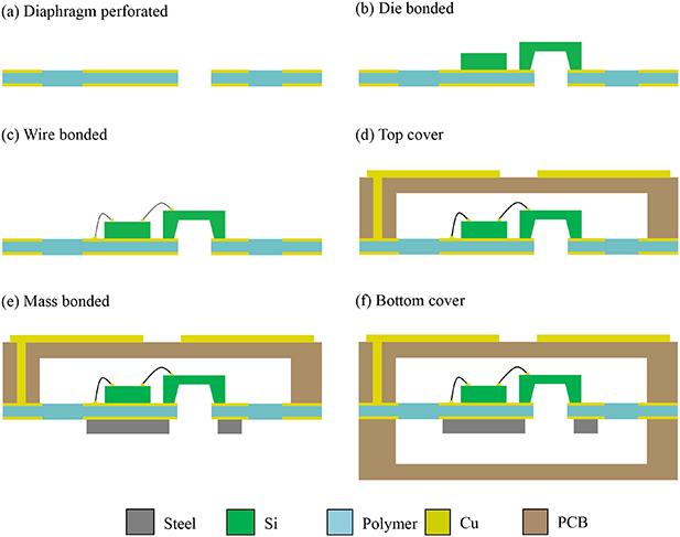
Figure 7. The packaging and assembly process steps to implement the presented BCM.
Download figure:
Standard image High-resolution image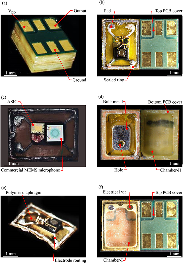
Figure 8. The micrographs of typical fabrication results, (a) the exterior of the fabricated and packaged BCM, (b) the front side view of the BCM after removing the top PCB cover, (c) zoom-in of the BCM to show the MEMS and ASIC chips and their wire bonding, (d) the back side view of the BCM after removing the bottom PCB cover, and the cavity on PCB for chamber-II and the bulk metal are observed; (e) the polymer diaphragm after removing both top and bottom PCB covers, and (f) the front side and back side views of the top PCB cover to show bonding pads, electrical vias, and the cavity for chamber-I.
Download figure:
Standard image High-resolution image4. Measurement and results
The schematic illustration in figure 9(a) shows the measurement setup for the presented sensor. As displayed in the micrograph, the BCM sample in figure 9(a) was wire bonded and mounted on a PCB as the device-under-test (DUT). Moreover, the testing system includes the reference accelerometer, the acoustic analyzer, and the shaker and controller. The shaker is used to animate the excitation from skull vibration. The DUT is excited by the shaker at a given swept vibration frequency of 100 Hz to 10 kHz, and with driving magnitudes ranging between 1 g to 4 g. A commercial reference accelerometer (PCB model 352C66) is employed to calibrate and monitor the vibration level of shaker. Measurement results in figure 9(b) depict the typical dynamic responses of the presented BCM sensor. The presented BCM has a resonant frequency at 9.5 kHz, and its ±5 dB bandwidth is ranging 100 Hz∼6.7 kHz. Since the commercial microphone has vent valves on the diaphragm, the sensitivity is slightly dropped at the low frequency regions. The results agree with the simulations in figure 5(b). Note that due to the bone-skin vibration transmission loss, the higher frequency excitation will be damped in real applications. Measurements in figure 10 further show responses of a BCM at different excitation amplitudes, and also repeatability of responses for different BCMs. of the respectively show responses from signal output recorded during the swept excitation levels. Figure 10(a) depicts the frequency responses of the BCM driving at 1 g to 4 g. The sensitivities of BCM are −38.8 dBV (for 1 g excitation) and −26.9 dBV (for 4 g excitation) at 1 kHz, and the ±5 dB bandwidth for these four different excitation levels are all ranging 100 Hz∼6.7 kHz. Moreover, as shown in figure 10(b), the frequency responses are measured from three different samples. It indicates that the presented BCM has good repeatability on the performance, and hence the feasibility of presented approach is demonstrated. In summary, the presented BCM has a sensitivity of −38.8 dBV g−1 and THD < 0.48% at 1 kHz. Measurements in figure 10(c) indicates the noise floor of the presented BCM is −84.7 dBV after integrating over the operation bandwidth of 100 Hz to 6.7 kHz. Since the sensitivity of the presented BCM is −38.8 dBV g−1, its signal to noise ratio (SNR) is 45.9 dB and its minimum detectable acceleration is 1.16 mg. Based on the specification of commercial products, the maximum acceleration tested in this study is 4 g. As a result, the dynamic range of BCM demonstrated in this study is 1.16 mg to 4 g. This study established the test setup in figure 11(a) to measure the crosstalks introduced from the excitations in unwanted directions (Ax and Ay in figure 7). The bracket is used to mount the DUT on the shaker for the excitations of Ax and Ay . Measurements in figure 11(b) show the sensitivity of the presented BCM when respectively applying 1 g excitation in three different directions Ax, Ay , and Az . To compare the measurements at 1 kHz, the sensitivity resulted from the Az excitation is 21.9 dB higher than that from the Ay excitation, and is 28.2 dB higher than that from the Ax excitation. Thus, the presented BCM is much more sensitive to the excitation from the sensing axis which agrees well with the simulation in figure 6.

Figure 9. (a) The measurement setup to evaluate the performances of the fabricated BCM, and the DUT is displayed in the micrograph, and (b) typical dynamic responses of the presented BCM sensor when driven at 1 g.
Download figure:
Standard image High-resolution image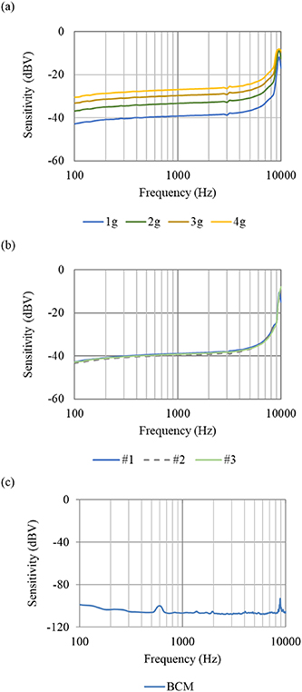
Figure 10. The dynamic responses of the presented BCM measured at various conditions, (a) the frequency ranges of 100 Hz∼10 kHz with amplitudes from 1 g to 4 g, (b) measurements for 3 different samples at 1 g excitation, and (c) the noise floor.
Download figure:
Standard image High-resolution image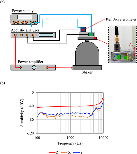
Figure 11. (a) The measurement setup to evaluate crosstalks of the fabricated BCM, and (b) typical dynamic responses of the presented BCM sensor when applying 1 g excitation in three different directions Ax, Ay , and Az.
Download figure:
Standard image High-resolution imageThis study performs tests to show the advantages of the presented BCM with respect to the conventional MEMS accelerometer and acoustic microphone. Firstly, this study displays typical measured dynamic responses (under 1 g excitation at 1 kHz) of the presented BCM and the commercial MEMS accelerometer, as shown in figure 12(a). Moreover, as shown in figure 12(b), the frequency responses (100 Hz∼10 kHz) of the presented BCM and commercial accelerometer are also characterized. To easily compare the bandwidth of BCM and accelerometer from frequency responses, measurement results in figure 12(b) are normalized at 1 kHz. The results indicate the bandwidth (100 Hz∼6.7 kHz, ±5 dB) of presented BCM is better than that of the commercial accelerometer (⩽2550 Hz, ±5 dB). This study further performs tests to compare the performances of acoustic microphone and the presented BCM under a noisy environment. As shown in figure 13(a) is the experiment setup. The acoustic microphone and the presented BCM are mounted on a commercial earphone. The voice from speaker will simultaneously be recorded by the acoustic microphone and the presented BCM. Meanwhile, a loudspeaker is used to provide a noise to influence the signals recorded by the acoustic microphone and BCM. The photos and illustration in figure 13(b) display the MEMS acoustic microphone and the presented BCM attached to the earphone for test. Figure 14 shows the related experiment results. Figure 14(a) depicts the human voice signal measured by the acoustic microphone and the presented BCM simultaneously. The results indicate that the human voice is properly recorded by both microphones without ambient noise. Figure 14(b) further shows the human voice signal measured by the acoustic microphone and the presented BCM after introduce ambient noise provided by the loudspeaker. The results indicate that the human voice can still be properly recorded by the BCM. However, the human voice can not be distinguished by the MEMS acoustic microphone in this case. Thus, the present BCM could enhance the communication quality in harsh environment. Figure 15 further shows the normalized amplitude FFT analysis for the first three voice periods (in figure 14(a)) respectively recorded by the presented BCM and the MEMS acoustic microphone. The results depict that high frequency range signals of BCM is decayed due to the bone-skin vibration transmission loss. Therefore, the voice periods recorded from the BCM and the acoustic microphone in figure 14(a) are not identical.
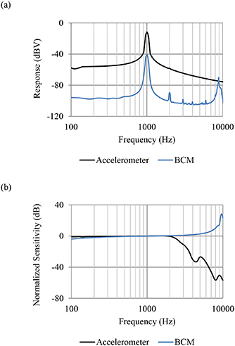
Figure 12. Comparison of the commercial accelerometer and the presented BCM, (a) dynamic responses under 1 g excitation when driven at 1 kHz, and (b) normalized frequency responses (at 1 kHz) under 1 g excitation when driven from 100 Hz to 10 kHz.
Download figure:
Standard image High-resolution image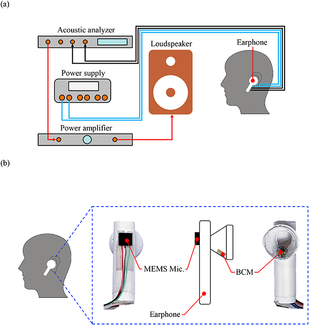
Figure 13. The voice recording tests of the presented BCM and a conventional MEMS acoustic microphone, (a) the measurement setups, and (b) the BCM and MEMS acoustic microphone assembled on a commercial earphone.
Download figure:
Standard image High-resolution image
Figure 14. Signals simultaneously recorded by the presented BCM and a conventional MEMS acoustic microphone, (a) when applying the human voice only, and (b) when applying both the human voice and the noise from loudspeaker.
Download figure:
Standard image High-resolution image
Figure 15. The normalized amplitude FFT analysis for the first three voice periods (in figure 15) recorded by the BCM and the MEMS acoustic microphone, (a) the first voices period, (b) the second voice period, and (c) the third voice period.
Download figure:
Standard image High-resolution image
5. Conclusions
The BCM has no sound port on its enclosure, and hence the BCM could only detect the voice from users and the influences of noise, wind, dust, and water from environment can be avoided. This study presents the design and implementation of a BCM by using the packaging of a commercial MEMS microphone, an ASIC chips, and a bulk metal on a flexible polymer diaphragm inside two PCB covers. Thus, two sealed chambers partitioned by an equivalent spring-mass system is established to form the BCM. In speech, the skull (vocal folds) vibration will excite the equivalent spring-mass system of the presented BCM, and further cause the time-dependent volume and pressure change in two sealed chambers. For the presented design, one chamber pressure will increase and another will decrease. The pressure difference between two sealed chambers will lead a time-dependent pressure load on the commercial MEMS microphone. As a result, the skull vibration could introduce a higher pressure load as well as a larger sensing signal for the presented BCM. To demonstrate the feasibility of the presented approach, the device with the dimensions of 3.5 × 2.65 × 1.48 mm3 is implemented using the packaging and assembly of the commercial MEMS microphone with polymer diaphragm and bulk metal. Measurements show the device has a sensitivity of −38.8 dB, THD < 0.48% at 1 kHz with 1 g excitation, SNR > 45 dB, and ±5 dB bandwidth for 100 Hz∼6.7 kHz. The frequency responses of three different samples are performed to show the well repeatability of performances for fabricated devices. The sensitivities on non-sensing axes are investigated in this paper as well. Measurements show the crosstalks with 1 g excitation (at 1 kHz) on x-axis and y-axis are −28.2 dBV and −21.9 dBV respectively related to z-axis. Moreover, comparing with the commercial accelerometer, the presented BCM has wider bandwidth (up to 6.7 kHz) than the accelerometer for bone conduction application; and comparing with the acoustic microphone, the presented BCM could enhance the communication quality in harsh environment. Nevertheless, the relatively complicated assembly process is required to implement the presented BCM. As a future perspective, by using the MEMS fabrication and wafer level packaging processes would be a better solution to realize the presented design.
Acknowledgments
This project was supported by the 1more Corp. of Taiwan. The authors would also like to appreciate the Gettop Acoustic Co., Ltd. of China for providing the fabrication and assembly facilities, and the commercial MEMS sensor and the related ASIC.