


1 The need for polarized beams
Spin-polarized particle beams are commonly used in nuclear and particle physics to study the interaction and structure of matter, and to test the Standard Model of particle physics[Reference Moortgat-Pick, Abe and Alexander1–Reference Androić, Armstrong and Asaturyan4]. In particular, the structure of sub-atomic particles like protons or neutrons is explored to get further insights into quantum chromodynamics (QCD)[Reference Burkardt, Miller and Nowak5] or to probe the nuclear spin structure[Reference Ageev, Alexakhin and Alexandrov6]. Polarized particle beams are also advantageous for achieving a deeper understanding of nuclear reactions[Reference Glashausser7], to search for symmetry violations, to pin down quantum numbers of new particles[Reference Rathmann, Saleev and Nikolaev2,Reference Jaffe8–Reference Adlarson10] or to investigate molecular dynamics[Reference Gay11,Reference Bederson12] .
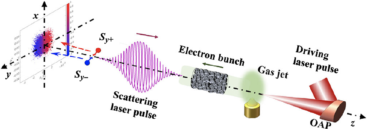
Figure 1 Scenario of the generation of spin-polarized electron beams via nonlinear Compton scattering: a relativistic electron bunch generated by laser-wakefield acceleration collides head-on with an elliptically polarized laser pulse and splits along the propagation direction into two parts with opposite transverse polarization[Reference Li, Shaisultanov and Hatsagortsyan34]. OAP, optical parametric amplification.
The technique for producing polarized beams depends not only on the particle species, but also on their kinetic energies. For stable ones, such as electrons or protons, polarized sources can be employed with subsequent acceleration in a linear accelerator or a synchrotron. For unstable particles, like muons, polarization-dependent particle decays are exploited[Reference Grange, Guarino and Winter3], while stable secondary beams, like antiprotons, might be polarized in dedicated storage rings by spin-dependent interactions[Reference Rathmann, Lenisa and Steffens13]. Electron or positron beams also spontaneously polarize in the magnetic fields of storage rings due to the emission of spin-flip synchrotron radiation, the so-called Sokolov–Ternov effect[Reference Sokolov and Ternov14–Reference Mane, Shatunov and Yokoya16]. This effect was first experimentally observed with low degrees of polarization[17,Reference Baier18] , and later utilized at several electron rings to generate a highly polarized beam during storage[Reference Camerini, Cline and Learned19–Reference Barber, Bremer and Böge25].
All of the above scenarios still rely on conventional particle accelerators that are typically very large in scale and budget[Reference Mane, Shatunov and Yokoya16]. In circular accelerators, depolarizing spin resonances must be compensated by applying complex correction techniques to maintain the beam’s polarization[Reference Khoe, Kustom and Martin26–Reference Lehrach, Bechstedt and Dietrich32]. In linear accelerators, such a reduction of polarization can be neglected due to the very short interaction time between particle bunches and the accelerating fields.
Concepts based on laser-driven acceleration at extreme light intensities have been promoted during recent decades. Ultra-intense and ultra-short laser pulses can generate accelerating fields in plasmas that are at the order of tera-volts per meter, about four orders of magnitude greater compared to conventional accelerators. The goal, therefore, is to build the next generation of highly compact and cost-effective accelerator facilities using a plasma as the accelerating medium; see for example Ref. [Reference Walker, Alesini and Alexandrova33]. Despite many advances in the understanding of the phenomena leading to particle acceleration in laser–plasma interactions, however, a largely unexplored issue is how an accelerator for strongly polarized beams can be realized. In simple words, there are two possible scenarios: either the magnetic laser or plasma fields can influence the spin of the accelerated beam particles, or the spins are too inert, such that a short acceleration has no influence on the spin alignment. In the latter case, the polarization would be maintained throughout the whole acceleration process, but a pre-polarized target would be required.
In this paper, we review the concepts and methods that could lead to the generation of polarized particle beams based on ultra-intense lasers. We focus on two main approaches. The first one is devoted to collision between unpolarized high-energy electron beams and ultra-relativistic laser pulses, introduced in Section 2.1. Section 2.2 focuses on concepts for pre-polarized targets for sequential particle acceleration. Suitable targets are described in Section 7.
2 Concepts
2.1 Polarization build-up from interactions with relativistic laser pulses
Strong-field quantum electrodynamics (QED) processes – like nonlinear Compton scattering and radiation reactions – can strongly modify the dynamics of light charged particles, such as electrons or positrons. Analogous to the Sokolov–Ternov effect in a strong magnetic field, electrons can rapidly spin-polarize in ultra-strong laser fields due to an asymmetry in the rate of spin-flip transitions, i.e., interactions where the spin changes sign during the emission of a γ-ray photon. Several such scenarios have been discussed in the literature; for a more quantitative discussion we refer to Section 4.
-
(1) Li et al.[Reference Li, Shaisultanov and Hatsagortsyan34,Reference Guo, Wang and Shaisultanov35] describe electron radiative spin effects by a Monte Carlo spin-resolved radiation approach in the local constant field approximation. Due to a spin-dependent radiation reaction, a monochromatic, elliptically polarized laser pulse can split an initially unpolarized relativistic electron ensemble along the propagation direction into two oppositely transversely polarized parts; see Figure 1.
A similar spin-dependent deflection mechanism is found by Geng et al.[Reference Geng, Ji and Shen36], who study the spin-correlated radiation-reaction force during the interaction of an initially polarized electron bunch with a linearly polarized laser pulse. The discovered mechanism dominates over the Stern–Gerlach force, which can provide a new perspective for studying spin-dependent QED effects.
-
(2) Del Sorbo et al.[Reference Sorbo, Seipt and Blackburn37,Reference Seipt, Del Sorbo and Ridgers38] calculate the rate of spin-flip transitions for electrons circulating at the magnetic nodes of two colliding, circularly polarized laser pulses; see Figure 2. They find that a sizeable (
 $\underset{\sim }{>}$
50%) spin polarization is expected in one laser period for lasers of an intensity within the reach of next-generation laser systems.
$\underset{\sim }{>}$
50%) spin polarization is expected in one laser period for lasers of an intensity within the reach of next-generation laser systems.Seipt et al.[Reference Del Sorbo, Seipt and Thomas39] also demonstrate that the electron orbits involved are unstable and study the robustness of the spin polarization when accounting for the instability of an electron trajectory in a magnetic node using a deterministic model for the radiation-reaction force. They point out that depolarization effects due to chaotic spin precession may strongly limit the achievable electron polarization. In addition, stochasticity – which may affect the rate of migration of the electrons from the magnetic node – needs further investigation. For these reasons, a more promising approach seems to be the following.
-
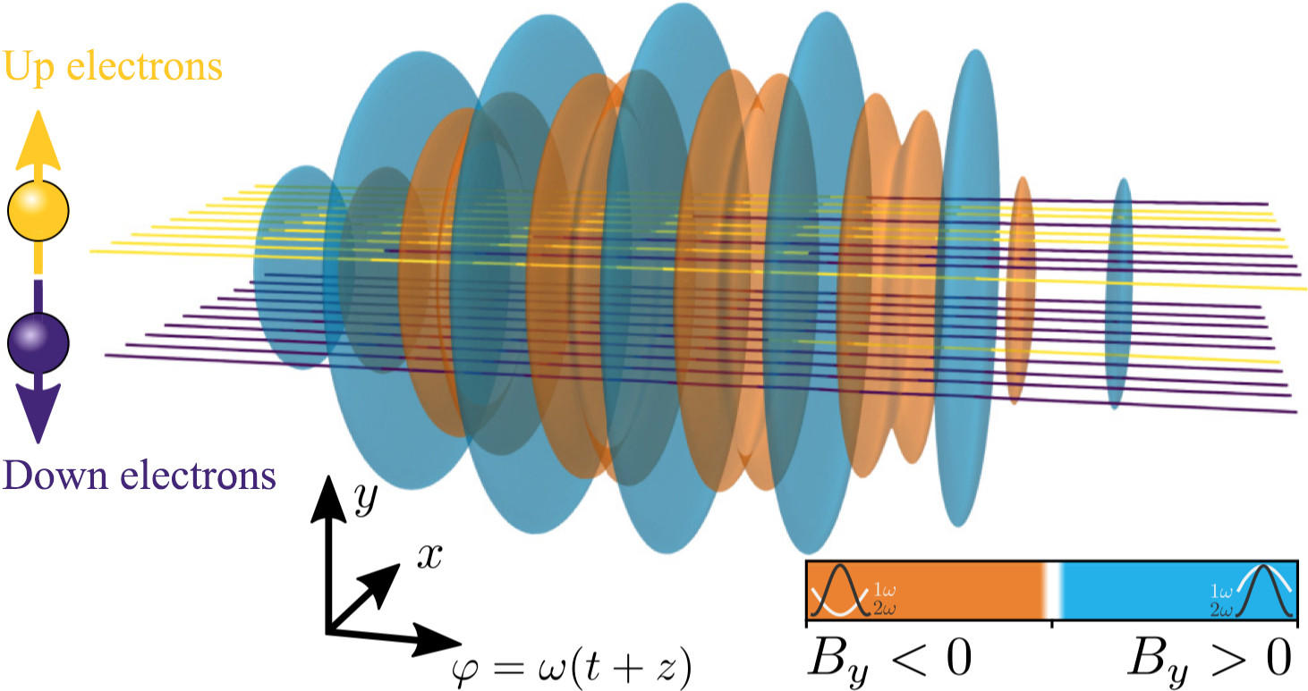
(3) Radiative polarization of high-energy electron beams in collisions with ultra-short pulsed bichromatic (two-color) laser fields has been proposed by Seipt et al.[Reference Seipt, Del Sorbo and Ridgers40] and Song et al.[Reference Song, Wang and Li41]. The scheme is depicted in Figure 3 and is based on the asymmetric distribution of the field structure that deflects spin-up/down electrons via quantum radiation reaction.
Figure 2 Schematic representation of electron spin polarization employing the standing wave of two colliding, circularly polarized laser pulses[Reference Del Sorbo, Seipt and Thomas39].
Figure 3 Electrons propagating through a bichromatic laser pulse perform spin-flips dominantly in certain phases of the field: electrons initially polarized along the +y direction (yellow trajectories) flip their spin to down (trajectory colored purple) dominantly when By > 0, and this is where 1ω and 2ω add constructively (blue contours). The opposite spin-flip dominantly happens when By < 0, where the 1ω and 2ω components of the laser are out of phase (orange contours)[Reference Seipt, Del Sorbo and Ridgers40].
-
(4) For the production of polarized positron beams, Chen et al.[Reference Chen, He and Shaisultanov42] employ a similar scheme as used by Seipt et al.[Reference Seipt, Del Sorbo and Ridgers40] and Song et al.[Reference Song, Wang and Li41] for electrons. An intense linearly polarized two-color laser pulse collides head-on with an unpolarized relativistic electron beam, resulting in the emission of photons in the forward direction, which subsequently decay into polarized e+/e− pairs, with spins parallel and antiparallel, respectively, to the laser’s magnetic field direction, and with a small divergence angle in the propagation direction (see Figure 4).
Figure 4 Scheme for laser-based polarized positron beam production[Reference Chen, He and Shaisultanov42].
Wan et al.[Reference Wan, Shaisultanov and Li43] suggest the use of an ultra-intense elliptically polarized laser pulse that collides head-on with an unpolarized electron bunch (similar to Li et al.[Reference Li, Shaisultanov and Hatsagortsyan34] for electrons). Again, the radiated high-energy photons decay into polarized electron–positron pairs due to the asymmetry of spin-dependent pair-production probabilities. The particles are then split into two beams due to the correlation of the spin-polarization with the particle momenta. In this scheme, the laser field is not asymmetric, and asymmetry of the pair-production probability is reflected in the angular separation of the oppositely polarized parts of the beam. This is in contrast to the work of Chen et al.[Reference Chen, He and Shaisultanov42], where an asymmetric two-color laser field is applied for positron polarization, though yielding considerably less polarization and larger angular spreading. Finally, Li et al.[Reference Li, Chen and Wang44] investigate theoretically the feasibility of the production of longitudinally polarized relativistic positron beams – which are potentially more useful for applications than transversely polarized ones – via the interaction of a circularly polarized laser pulse with a fully longitudinally spin-polarized counter-propagating relativistic electron beam in the quantum radiation-dominated regime.


2.2 Polarized beams from pre-polarized targets
-
(1) Wen et al.[Reference Wen, Tamburini and Keitel45] and Wu et al.[Reference Wu, Ji and Geng46] have put forward a method for generating intense polarized electron beams. It is based on the electron polarization of a gas jet via photo-dissociation by a circularly polarized ultra-violet (UV) laser pulse followed by electron laser-wakefield acceleration (LWFA) by an intense laser pulse. This scheme is illustrated in Figure 5.
Assuming that at the moment of irradiation with the accelerating multi-terawatt laser pulse the electrons in the target are fully polarized (see Section 7 for target details), one has to optimize the injection into the wakefield and the subsequent acceleration to multi-mega-electron volt (MeV) energies such that a high degree of electron polarization is maintained. These processes can be modeled with the help of full three-dimensional particle-in-cell (PIC) simulations, incorporating the spin dynamics via the Thomas–Bargmann Michel Telegdi (T–BMT) equation (see Equation (2) below)[Reference Vieira, Huang and Mori47,Reference Thomas, Hützen and Lehrach48] . A couple of such codes have been developed recently, and used for the modeling of polarized electron[Reference Wen, Tamburini and Keitel45,Reference Wu, Ji and Geng46,Reference Wu, Ji and Geng49,Reference Wu, Ji and Geng50] and proton[Reference Hützen, Thomas and Böker51–Reference Jin, Wen and Zhang54] beam generation.
-
(2) In a subsequent paper, Wu et al.[Reference Wu, Ji and Geng50] apply their scheme developed by Wu et al.[Reference Wu, Ji and Geng46] to wakefield acceleration driven by a particle beam (PWFA). In this scheme, the unpolarized electron driver beam can be generated via the well-understood LWFA. The electron-beam driver is free of the prepulse issue associated with a laser driver, thus eliminating possible depolarization of the pre-polarized gas due to ionization by a prepulse.
-
(3) The first applications of pre-polarized targets employed by Wen et al.[Reference Wen, Tamburini and Keitel45] and Wu et al.[Reference Wu, Ji and Geng46,Reference Wu, Ji and Geng49,Reference Wu, Ji and Geng50] were actually aiming at the laser-induced acceleration of proton beams[Reference Hützen, Thomas and Böker51–Reference Jin, Wen and Zhang54]. This is because protons have much smaller magnetic moments and, therefore, their spin alignment in the plasma magnetic fields is much more inert as compared to electrons. Also, from the target point-of-view, polarized nuclei can be provided more easily than electrons (see Section 7), and the necessary proton polarimetry can be achieved in a straight-forward manner (see Section 8). Figure 6 shows the schematic layout of a laser-based accelerator for polarized proton beams, which is simpler than the set-up shown in Figure 5 because the 234.62 nm UV light for Cl ionization is not required. The first description of this scheme can be found in Ref. [Reference Hützen, Thomas and Böker51].
Figure 5 Sketch of the all-optical laser-driven polarized electron acceleration scheme using a pre-polarized target[Reference Wu, Ji and Geng46]. LG, Laguerre–Gaussian; OAP, optical parametric amplification.
Figure 6 Schematic diagram showing laser acceleration of polarized protons from a dense hydrogen chloride gas target (brown). HCl molecules are initially aligned along the accelerating laser (indicated by the green area) propagation direction via a weak infrared (IR) laser. Blue and white balls represent the nuclei of hydrogen and chlorine atoms, respectively. Before the acceleration, a weak circularly polarized UV laser (purple area) is used to generate the polarized atoms along the longitudinal direction via molecular photo-dissociation. The brown curve indicates the initial density distribution of the gas-jet target. The polarized proton beam is shown on the right (blue) with arrows (red) presenting the polarization direction[Reference Jin, Wen and Zhang54].
-
(4) The first attempt to experimentally study spin effects during laser-induced acceleration is based on a nuclear polarized
${}^3$
He target[Reference Engin, Büscher and Deppert55,Reference Engin, Chitgar and Deppert56] . These experiments profit from the fact that hyperpolarized 3He gas can be produced rather easily and maintains its nuclear polarization over several days at ambient room temperature and under small magnetic holding fields (Section 7). The main goal of these studies is to demonstrate nuclear polarization conservation in a (laser-induced) plasma. This would open the possibility of inertial confinement fusion with spin-polarized fuel, in which the cross-sections for nuclear fusion reactions can be enhanced, leading to higher energy yields compared to the case of unpolarized fuel[Reference Ciullo, Engels and Büscher57]. Another goal is to realize an intense spin-polarized 3He-ion source, which is extremely challenging with conventional approaches. The main experimental challenge – besides the preparation of the polarized helium target – is the demonstration of laser-induced ion acceleration out of gas-jet targets. This has recently been achieved in a feasibility study with an unpolarized gas-jet target performed at PHELIX, GSI Darmstadt, where helium ions with energies of a few MeV have been observed; see Figure 7. Thus, the ion energies are sufficiently high for the polarimetry (see Section 8) in a beam time with a polarized target, scheduled for fall 2020.
Figure 7 Measured 3,4He2+ energy spectra accelerated from unpolarized helium gas jets[Reference Engin, Chitgar and Deppert56]. IP, image plate.


3 Theoretical background
It is still an issue for current research how particle spins are affected by the huge electromagnetic fields that are inherently present in laser-induced plasmas or in the laser fields themselves, and what mechanisms may lead to the production of highly polarized beams. Early attempts to describe these processes can be found in Refs. [Reference Vieira, Huang and Mori47,Reference Kotkin, Serbo and Telnov58]. A schematic overview of the interplay between single particle trajectories (blue), spin (red) and radiation (yellow) is shown in Figure 8; details can be found in Ref. [Reference Thomas, Hützen and Lehrach48].
When particle spins are treated in the semiclassical limit, it is the T–BMT equation[Reference Thomas59,Reference Bargmann, Michel and Telegdi60] that determines the spin precession of individual particles around the local electromagnetic field lines. If particles with mass m, charge
 $q\cdot e$
, anomalous magnetic moment a and velocity
$q\cdot e$
, anomalous magnetic moment a and velocity
 $\overrightarrow{v}$
move in an electromagnetic field
$\overrightarrow{v}$
move in an electromagnetic field
 $\overrightarrow{E}$
,
$\overrightarrow{E}$
,
 $\overrightarrow{B}$
with vanishing gradient, their spin vectors
$\overrightarrow{B}$
with vanishing gradient, their spin vectors
 $\overrightarrow{s_{\mathrm{i}}}$
precess according to
$\overrightarrow{s_{\mathrm{i}}}$
precess according to

Figure 8 Sketch of the interplay between single particle trajectories (blue), spin (red) and radiation (yellow)[Reference Thomas, Hützen and Lehrach48].
 $$\begin{align}\frac{\mathrm{d}\overrightarrow{s_{\mathrm{i}}}}{\mathrm{d}t}=-\overrightarrow{\varOmega}\times \overrightarrow{s_{\mathrm{i}}}.\end{align}$$
In cgs units the rotational frequency
 $\overrightarrow{\varOmega}$
is given by[Reference Mane, Shatunov and Yokoya16]
$\overrightarrow{\varOmega}$
is given by[Reference Mane, Shatunov and Yokoya16]
 $$\begin{align}\overrightarrow{\varOmega}=\frac{q\cdot e}{mc}\left[{\varOmega}_{\mathrm{B}}\cdot \overrightarrow{B}-{\varOmega}_{\mathrm{v}}\left(\frac{\overrightarrow{v}}{c}\cdot \overrightarrow{B}\right)\frac{\overrightarrow{v}}{c}-{\varOmega}_{\mathrm{E}}\frac{\overrightarrow{v}}{c}\times \overrightarrow{E}\right],\end{align}$$
where
 $$\begin{align}{\varOmega}_{\mathrm{B}}=a+\frac{1}{\gamma},\; {\varOmega}_{\mathrm{v}}=\frac{a\gamma}{\gamma +1},\; {\varOmega}_{\mathrm{E}}=a+\frac{1}{1+\gamma}.\end{align}$$
Spin precession is a deterministic process and can be calulated by treating the spin as an intrinsic electron magnetic moment. In the non-QED regime, only a theory, which contains the T–BMT equation, describes the particle and spin motion in electromagnetic fields in a self-consistent way.
Under classical and semi-classical limits, the acceleration of charged particles is treated within the framework of classical field theory. This theory also describes the reaction of the particle motion due to radiation, if the particle energy and/or laser field strength is sufficiently high. Introducing spin into electron dynamics leads to a spin-dependent radiation reaction. The radiation power of electrons in different spin states varies such that they feel a stronger radiation-reaction force when the spins are anti-parallel to the local magnetic field in the rest frame of the radiating electron, which can lead to a split of electrons with distinctive spin states.
The Stern–Gerlach force primarily influences the trajectory of a particle. In general, the radiation-reaction force exceeds the Stern–Gerlach force by far if the particles are relativistic (kinetic energies well above 1 GeV) or even ultra-relativistic (above 1 TeV) (see also Ref. [Reference Geng, Ji and Shen36]). There are, however, some field configurations that reverse this situation, so that the radiation-reaction force can be neglected compared to the Stern–Gerlach force (see e.g., Ref. [Reference Flood and Burton61]).
A direct coupling between single particle spins and radiation fields is treated in the context of quantum field theory. Within this theory, the mechanism that describes the spontaneous self-polarization of an accelerated particle ensemble is known as the Sokolov–Ternov effect. The stochastic spin diffusion from photon emission is a non-deterministic process resulting in the rotation of the spin vector in the presence of a magnetic field with the emission of a photon.
A discussion of the generalized Stern–Gerlach force shows that the trajectories of individual particles are perturbed by a change of the particle’s motion induced by the T–BMT equation rather than by coupling of the spin to the change of the particles’ energy or velocity rates; while even small field variations must be taken into account[Reference Thomas, Hützen and Lehrach48]. With regard to a possible polarization build-up through spin-dependent beam split effects, it is found that a tera-electron volt electron beam has the best option to be polarized when the plasma is dense enough and the acceleration distance (time) is large enough. For protons, we do not see any realistic case to build up a polarization by beam separation. In conventional circular accelerators, the Sokolov–Ternov effect restores the alignment of the spins in experimentally proven polarization times in the range of minutes or hours, depending on the energy of the beam and the bending radius of the beam in bending magnets. The scaling laws for laser-plasma fields predict that the spins of electron moving in strong (≈1017 V/m) fields should be polarized in less than a femtosecond[48].
Del Sorbo et al.[Reference Sorbo, Seipt and Blackburn37,Reference Del Sorbo, Seipt and Thomas39] proposed that this analog of the Sokolov–Ternov effect could occur in the strong electromagnetic fields of ultra-high-intensity lasers, which would result in a buildup of spin polarization in femtoseconds for laser intensities exceeding 5 × 10²² W/cm2. In a subsequent paper[Reference Seipt, Del Sorbo and Ridgers38] they develop a local constant crossed-field approximation of the polarization density matrix to investigate numerically the scattering of high-energy electrons from short, intense, laser pulses.
Description of the spin-dependent dynamics and radiation in optical laser fields requires a classical spin vector that precesses during photon emission events following the T–BMT equation. This is accomplished by projecting the spin states after each emission onto a quantization axis. The latter could be the local magnetic field in the rest frame of the radiating electron[Reference Li, Shaisultanov and Hatsagortsyan34,Reference Chen, He and Shaisultanov42] . Alternatively, Seipt et al.[Reference Seipt, Del Sorbo and Ridgers40] suggest that the spin orientation either flips or stays the same, depending on the radiation probability. It has recently been pointed out by Geng et al.[Reference Geng, Bu and Wu62] that, by generalizing the Sokolov–Ternov effect, the polarization vector consisting of the full spin information can be obtained.
4 Model calculations I: strong field QED
Figure 9 shows the prediction from Li et al.[Reference Li, Shaisultanov and Hatsagortsyan34] for the splitting of an well-collimated, initially unpolarized electron beam after the interaction with an elliptically polarized laser pulse. It is seen that typical electron deflection angles of a few mrad can be achieved. It is concluded that from a separation of the electron distribution with θy > 0 (or < 0) one can obtain an electron beam with positive (or negative) transverse polarization of roughly 34%. This number can even be increased to approximately 70% by excluding the electrons near θy = 0. This is, however, at the expense of a significantly reduced electron flux, and would require a very precise control of the shot-to-shot electron divergence angle.

Figure 9 (a) Transverse distribution of the electron spin component Sy as a function of the deflection angles θx,y ; (b) corresponding logarithmic electron-density distribution. The assumed laser peak intensity is I ≈ 1.38 × 10²² W/cm2 (a 0 = 100), wavelength λ = 1 μm, the pulse duration amounts to five laser periods, focal radius 5 μm and ellipticity 0.05. The electron bunch with kinetic energy of 4 GeV and energy spread 6% has an initial angular divergence of 0.3 mrad[Reference Li, Shaisultanov and Hatsagortsyan34].
In a follow-up paper, Guo et al.[Reference Guo, Wang and Shaisultanov35] investigate stochasticity effects in radiative polarization of a relativistic electron beam head-on colliding with an ultra-strong laser pulse in the quantum radiation-reaction regime. These enhance the splitting effect into the two oppositely polarized parts as described by Li et al.[Reference Li, Shaisultanov and Hatsagortsyan34]. Consequently, an increase of the achievable electron polarization by roughly a factor of two is predicted at the same required high accuracy for the selection of the electron deflection angles.
Another paper from Li et al.[Reference Li, Guo and Shaisultanov63] investigates the impacts of spin polarization of an electron beam head-on colliding with a strong laser pulse on the emitted photon spectra and electron dynamics in the quantum radiation regime. Using a formalism similar to that of Li et al.[Reference Li, Shaisultanov and Hatsagortsyan34], they developed an alternative method of electron polarimetry based on nonlinear Compton scattering in the quantum radiation regime. Beam polarization can be measured via the angular asymmetry of the high-energy photon spectrum in a single-shot interaction of the electron beam with a strong laser pulse.
Seipt et al.[Reference Seipt, Del Sorbo and Ridgers40] propose the use of bichromatic laser fields to polarize electron beams and predict a measurable modification of the resulting quantum radiation reaction. They describe spin-dependent radiation-reaction effects, and use a Boltzmann equation for distribution functions of spin-polarized electrons. They also apply a quasi-classical tracking approach where electrons are pushed classically between photon emissions, and the emissions are treated fully quantum-mechanically using a Monte Carlo algorithm employing spin-dependent photon emission rates. In doing so, they can determine optimum parameters for achieving maximum radiative polarization. The χ 0–c 2 parameter scan shown in Figure 10 yields a maximum degree of polarization of about 17%.

Figure 10 Achievable degree of electron polarization as a function of a quantum nonlinearity parameter χ
0 and the bichromaticity parameter c
2 (defining the fraction of the total pulse energy in the second harmonic,
 ${c}_2^2/\left(1+{c}_2^2\right)$
). The calculations have been performed for 5 GeV electrons colliding with a 161 fs laser pulse, i.e., a
0(χ0 = 1) = 16.5[Reference Seipt, Del Sorbo and Ridgers40].
${c}_2^2/\left(1+{c}_2^2\right)$
). The calculations have been performed for 5 GeV electrons colliding with a 161 fs laser pulse, i.e., a
0(χ0 = 1) = 16.5[Reference Seipt, Del Sorbo and Ridgers40].
Song et al.[Reference Song, Wang and Li41] find that electron polarization strongly depends on the relative phase of the two-color laser pulse; see Figure 11. They conclude that, with realistic laser parameters, maximum degrees of polarization of roughly 10% seem within reach.

Figure 11 Average polarization Sy as a function of the relative phase ϕ of the two-color laser pulse for different laser waist radii σ 0. The assumed laser intensities are a 0,1 = 2a 0,2 = 100, I 1 = 4I 2 = 1.37 × 10²² W/cm2[ Reference Song, Wang and Li 41 ].
For positrons, rather high degrees of polarization seem to be achievable, even for currently achievable laser parameters. Chen et al.[Reference Chen, He and Shaisultanov42] employ a scenario with an initial electron energy of 2 GeV and laser full intensity a 0 = 83. It has been shown that highly polarized positron beams with 2 × 10⁴ particles and a polarization degree of 60% can be obtained within a small angular divergence of ~ 74 mrad. Wan et al.[Reference Wan, Shaisultanov and Li43] find that their optimal parameters include a laser intensity of the order of 1022 W/cm2, an ellipticity of the order of 0.03, a laser pulse duration less than about 10 cycles and an initial electron energy of several giga-electron volts (GeV). This leads to 86% polarization of the positron beam, with the number of positrons more than 1% of the initial electrons. As for the electron beams in Ref. [Reference Li, Shaisultanov and Hatsagortsyan34], however, the emission angles of the two positron beams with opposite polarization differ by only a few milliradians. Li et al. use a peak laser intensity of I = 2.75 × 10²² W/cm2 (a 0 = 141), a full width at half maximum (FWHM) pulse duration of five laser periods, laser wavelength 1 μm and focal radius 5 μm. The initial electron kinetic energy is 10 GeV, the energy spread 6% and the angular divergence 0.2 mrad[Reference Li, Chen and Wang44]. In this scenario, a highly polarized (up to 65%), intense (up to 106/bunch) positron beam can be obtained.
5 Model calculations II: particle-in-cell simulations
5.1 Electron acceleration
Wen et al.[Reference Wen, Tamburini and Keitel45] demonstrate that kilo-ampere (kA) polarized electron beams can be produced via laser-wakefield acceleration from a gas target. For this purpose, they implement the electron spin dynamics in a PIC code, which they use to investigate electron beam dynamics in self-consistent three-dimensional particle-in-cell simulations. By appropriately choosing the laser and gas parameters, they show that the depolarization of electrons induced by the laser-wakefield acceleration process can be as low as 10%. In the weakly nonlinear wakefield regime, electron beams carrying currents of the order of 1 kA and retaining the initial electronic polarization of the plasma can be produced. The predicted final electron beam polarization and current amount to (90.6%, 73.9%, 53.5%) and (0.31 kA, 0.59 kA, 0.90 kA) for a 0 = (1, 1.1, 1.2), respectively. Wen et al. point out that compared to currently available conventional sources of polarized electron beams, the flux is increased by four orders of magnitude.
Based on similar PIC simulations Wu et al. [Reference Wu, Ji and Geng46] predict even larger electron beam currents via vortex Laguerre–Gaussian (LG) laser-driven wakefield acceleration; see Figure 12. The topology of the vortex wakefield resolves the depolarization issue of the injected electrons. Their method releases the limit on beam flux for polarized electron acceleration and promises more than an order of magnitude boost in peak flux, as compared to Gaussian beams.

Figure 12 Prediction from Wu et al. [Reference Wu, Ji and Geng46] for the achievable electron polarization dependent upon the electron current. More than 80% polarization can be achieved when a vortex LG laser pulse is used for the acceleration.
Wu et al. [Reference Wu, Ji and Geng49] find that beam polarization depends on the azimuthal angle in a plasma wakefield due to the symmetric bubble field; see Figure 13. Accordingly, an X-shaped slit (spin filter) is proposed to significantly enhance beam polarization of the accelerated electrons. A beam polarization of about 80% is achieved by filtering out the low-polarization population using the slit, while the initial polarization is only about 35%.

Figure 13 Electron polarization distributions in the transverse phase space during laser-wakefield acceleration[Reference Wu, Ji and Geng49].
5.2 Heavy particles
Hützen et al. [Reference Hützen, Thomas and Böker51–Reference Hützen, Thomas and Lehrach53] present the first scheme for a laser-based accelerator for polarized particle beams using 3D PIC simulations with explicit spin treatment. They can show that proton polarization is sufficiently conserved during the acceleration process for foil[Reference Hützen, Thomas and Böker51] and gaseous[Reference Hützen, Thomas and Lehrach53] targets and, thus, suggest the use of pre-polarized monatomic gases from photo-dissociated hydrogen halide molecules in combination with peta-watt (PW) lasers. For an a 0 = 200 laser pulse they predict high degrees of polarization at proton energies of a few GeV; see Figure 14. Thus, it suggests the use of pre-polarized mono-atomic gases from photo-dissociated hydrogen halide molecules in combination with 10 PW class lasers.

Figure 14 Three-dimensional PIC simulation of proton acceleration assuming a gaseous HCl target with a hydrogen density of 8.5 × 1019 cm−3 and a circularly polarized laser pulse with 800 nm wavelength and a normalized amplitude of a 0 = 200. (a) Simulated proton density; (b) polarization as a function of the proton energy[Reference Hützen, Thomas and Lehrach53].
Jin et al. [Reference Jin, Wen and Zhang54] extend the PIC simulations to smaller, currently achievable, laser powers. They find that proton beams with an energy above 50 MeV and ~ 80% polarization can be obtained (see Figure 15) employing the magnetic vortex acceleration mechanism. Such measurements are now being prepared at the SULF facility of SIOM, Shanghai.

Figure 15 (a) Three-dimensional PIC simulation for a gaseous HCl target with molecular density of 1019 cm−3 and 1.3 PW laser with phase-space distribution; (b) spin spread of protons with energy E > 20 MeV on the Bloch sphere[Reference Jin, Wen and Zhang54].
No PIC simulations with treatment of spin effects have so far been carried out for particles heavier than protons. Only a scan of the parameter space (target density, laser pulse energy and duration) has been published[Reference Engin, Chitgar and Deppert56], aiming at the optimization of the ion flux and kinetic energy accelerated in a polarized gas-jet target; see Figure 16. It is seen that a channel in the ion density is generated via a combination of strong self-focusing and radial ponderomotive expulsion of electrons within the first 0.5 mm of the gas target, followed by filamentation and hosing for longer times. In general, a cleaner and longer channel is generated at lower densities; whereas the laser pulse is prone to filamentation and radial dispersion with increasing density. The influence of these structures on the ion spins is subject of ongoing simulations in the framework of JuSPARC[Reference Forschungszentrum Jülich64].

Figure 16 Simulated normalized He2+ ion-number density during the passage of a peta-watt laser pulse (6.5 ps after it entered the simulation box at the left boundary) through an unpolarized helium gas jet target. (a) 2%; (b) 3%; (c) 4%; (d) 12% critical density[Reference Engin, Chitgar and Deppert56].
6 Lessons learned from theoretical studies
From the literature outlined in Sections 2–5 it becomes clear that a wealth of (mostly theoretical) pathways towards the realization of laser-induced polarized particle acceleration have been put forward in recent years. These concepts strongly differ for the various particle species. In some cases it is necessary to wait for significant progress in laser technology. Our conclusions for a strategy aiming at the speedy realization of laser-induced polarized particle acceleration are given below.
-
(1) For currently realistic laser parameters, pre-polarized targets are needed to achieve electron beams with polarizations well above 10%. Such targets should provide high degrees of electronic polarization (> 50%) and should allow for operation at laser facilities (e.g., robustness against electromagnetic pulses (EMPs) and target heating).
-
(2) Due to their three-orders-smaller magnetic moments, measurable polarization for heavier particles (protons, ions) can only be achieved with nuclear pre-polarized targets.
-
(3) For positrons, no pre-polarized targets can be realized. Here, high degrees of polarization (90%) can be obtained from the scattering of peta-watt laser pulses off an unpolarized relativistic electron beam (which can be laser-generated). Such schemes require precise control of all involved beam pointings (to the few-milliradian level).
-
(4) Gas-jet targets are preferable to foil targets since they allow operation with state-of-the-art kilo-hertz laser systems. Low-density targets are also less challenging in terms of depolarizing effects.
7 Experimental techniques I: polarized targets
For the experimental realization of polarized beam generation from laser-induced plasmas, the choice of the target is a crucial point. Pre-polarized solid foil targets suitable for laser acceleration via target normal sheath acceleration (TNSA) or radiation-pressure acceleration (RPA) are not yet available, and their realization seems extremely challenging. In previous experiments, hydrogen nuclear polarization has mostly been realized through a static polarization, e.g., in frozen spin targets[Reference Keith, Brock and Carlin65] or with polarized 3He gas. For proton acceleration alone, polarized atomic beam sources based on the Stern–Gerlach principle are currently available, which, however, offer a too small particle density[Reference Nass, Baumgarten and Braun66]. To laser-accelerate polarized electrons and protons, a new approach with dynamically polarized hydrogen gas targets is needed. A statically polarized 3He target, a dynamically polarized hydrogen target for protons, as well as a hyperpolarized cryogenic target for the production and storage of polarized H2, D2 and HD foils are being prepared at the Forschungszentrum Jülich within the ATHENA project.
7.1 Static polarization: 3He
In order to develop a laser-driven spin-polarized 3He-ion beam source available for nuclear physics experiments as well as for the investigation of polarized nuclear fusion, one challenge is the provision of a properly statically polarized 3He gas-jet target. The essential components of such a target are a magnetic holding field for storing pre-polarized 3He gas for a long time duration within the PHELIX target chamber, and a non-magnetic nozzle for providing the desired gas-jet target (see Figure 17)[Reference Engin67]. All components must be designed such that the polarization is maintained sufficiently long for the experiments. A relaxation time of 20.9 h has already been achieved for a prototype of the setup[Reference Soltner, Büscher and Burgmer68].

Figure 17 Perspective view of the 3D model of the fully mounted magnetic system inside the PHELIX chamber[Reference Ciullo, Engels and Büscher57,Reference Engin67] .
The magnetic holding field consists of an outer Halbach array composed of an upper and lower ring of 48 NdFeB permanent magnets, 1100 mm in diameter, together with an inner Helmholtz coil array consisting of four single Helmholtz coils. In the Halbach array the permanent magnets are stacked at an optimum distance such that its field homogeneity is sufficiently high to maintain nuclear 3He polarization. The Helmholtz coils are oriented so that their magnetic field is aligned parallel to the laser-propagation direction. A single coil consists of a coiled Cu sheet with a width and thickness of 40 mm. The outer and inner diameters of the naked Cu coil are 789 mm and 709 mm, respectively. Both inner coils are separated by 285.75 mm, while the two single front/rear coils are separated by a distance of 218.95 mm. In contrast to electric coils, the permanent magnets used do not need to be cooled in vacuum, and they provide a constant field, even in the presence of huge EMPs[Reference Engin67].
The second essential component for the layout of a polarized 3He target is the gas-jet source. The pre-polarized 3He gas is delivered at an intrinsic pressure of 3 bar. By using a pressure booster built of non-magnetic materials, the desired final pressure can be reached (up to 30 bar). To synchronize the gas flux with the incoming laser pulse, a home-made non-magnetic valve with piezo actuators has been prepared. In order to generate a broad plateau-like density distribution with sharp density gradients, a supersonic de Laval nozzle is used.
7.2 Dynamic polarization: protons and electrons
For the realization of a dynamically polarized electron and ion source, a novel laser-based target system is under preparation: two laser beams for protons, and three beams for electron polarization, are focused into a gas jet made of bi-atomic linear molecules with at least one hydrogen atom, for example, HCl or HBr gas (see Figure 18)[Reference Wu, Ji and Geng46,Reference Hützen, Thomas and Böker51,Reference Büscher, Hützen and Engin52,Reference Forschungszentrum Jülich64,Reference Sofikitis, Rubio-Lago and Martin69,Reference Sofikitis, Bougas and Katsoprinakis70] .

Figure 18 The 1064 nm IR laser propagates along the x-axis to align the bonds of the HCl molecules, and then UV light with a wavelength of 213 nm, propagating along the z-axis, is used to photo-dissociate the HCl molecules. A 234.62 nm UV light is used to ionize the Cl atoms. Thermal expansion of the electrons creates a large Coulomb field that expels the Cl ions. A fully polarized electron target is therefore produced for sequential acceleration[Reference Wu, Ji and Geng46].
The special feature of the EKSPLA SL330 series JuSPARC_MIRA system[Reference Forschungszentrum Jülich64] is the simultaneous output of the fundamental wavelength at 1064 nm and the fifth harmonic at 213 nm, provided by a Nd:YAG crystal serving as the active medium. Operating at a repetition rate of 5 Hz and a pulse duration of 170 ps, the linear polarized fundamental beam is focused onto the gas jet with a pulse energy of 100 mJ. The molecular electric dipole moment μ is thus aligned relative to the electric field of the laser light, leading to an increased polarization signal. Simultaneously, but at an angle of 90°, the strongly focused circularly polarized fifth-harmonic beam with an intensity of about 1012 W·cm−2 is also guided into the vacuum chamber (Figure 19). The interaction with the already aligned HCl or HBr molecules leads to a photo-dissociation process by UV excitation and, finally, the polarization of the H nuclei via hyperfine spin beating with a period of about 350 ps. For the realization of a polarized electron target, unlike that for a polarized proton target, an additional third laser at 234.62 nm UV light to ionize the Cl or Br atoms is needed. The resulting thermal expansion of the electrons creates a large Coulomb field that expels the Cl or Br ions, together with their unpolarized electrons[Reference Wu, Ji and Geng46].

Figure 19 Technical drawing of the optical setup including the JuSPARC_MIRA laser system and the target chamber for the polarized proton target[Reference Forschungszentrum Jülich64].
The fifth-harmonic beam is guided by customized optics with the highest possible light reflectance (reflection > 98% at 45° incidence angle provided by Layertec GmbH) having a diameter of one inch for a beam diameter of 12 mm. A quartz quarter-wave plate with two-sided anti-reflection coating from EKSMA Optics converts the initially linearly polarized laser beam to circular polarization. Finally, the UV beam is focused below the HCl or HBr nozzle inside the interaction chamber. The fundamental beam at 1064 nm is guided by standard mirrors with dielectric Nd:YAG coatings and focused to an intensity of about 5 × 10¹³ W·cm−2 into the HCl or HBr gas. The gas is injected into the interaction chamber by a high-speed short-pulse piezo valve that can be operated at a maximum 5 bar inlet gas pressure to produce a gas density in the range of about 1019 cm−3[ Reference Hützen, Thomas and Böker 51 , Reference Forschungszentrum Jülich 64 ]. The valve is adjustable in height so that sufficient amounts of HCl or HBr molecules, which are spread in a cone-like shape, interact with the laser beams by keeping the backing pressure low, and thus the molecules’ mean free path large enough.
7.3 Hyperpolarized cryogenic targets
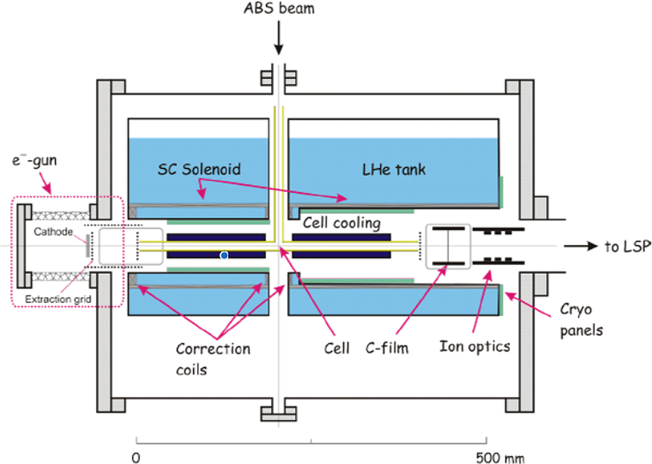
The investigation of the recombination of nuclear polarized hydrogen and deuterium atoms into polarized molecules gives new insights into different fields in physics and chemistry, aiming for the optimization of storage-cell gas targets for coming accelerators experiments and the production and handling of polarized fuel for future fusion reactors. In a joint collaboration of the St. Petersburg Nuclear Physics Institute (PNPI), the Institute for Nuclear Physics of the University of Cologne and the Institute for Nuclear Physics of the Forschungszentrum Jülich, the recombination processes on different surfaces, the polarization losses due to wall collisions and the polarization lifetime of the molecules have been studied. The dedicated experimental setup of the hyperpolarized cryogenic target is shown in Figure 20. A beam of hydrogen and/or deuterium atoms with selected nuclear and electron spin orientations is produced in a polarized atomic beam source (ABS). These polarized atoms enter a home-made T-shaped storage cell that is 400 mm long with a 100 mm long attachment for the atomic inlet (the outer diameter of the tube is 14 mm). In the cell, the atoms can recombine into molecules on the surface of the cell, which is exchangeable to enable measurements with different inner surface coatings on the fused-quartz wall materials, e.g., a gold surface, an additional water surface or a coating of Fomblin oil (perfluropolyether).

Figure 20 Schematic view of the interaction chamber for production and storage of polarized H2, D2, HD and
 ${\mathrm{HD}}_2^{+}$
foils[Reference Engels, Awwad and Clausen71].
${\mathrm{HD}}_2^{+}$
foils[Reference Engels, Awwad and Clausen71].
In the next step, a small pipe, to include an independent cooling and power supply, will be installed on one side of the cell having no direct contact with the cell. In this way, molecules can be generated and pre-cooled in the storage cell before they are frozen in the new pipe. Thus, the molecules in the storage cell can still be ionized and accelerated to measure their polarization. After the atomic flow is stopped, the pipe slowly warms up. In this way, the polarization of the molecules that have been frozen can be measured to compare the polarization values of the just-recombined molecules and those that are frozen into ice. The residual gas is pumped by cryogenic panels below 10−8 mbar without gas load to the cell. Using a superconducting solenoid at a temperature of 4 K, a magnetic field of up to 1 T in the storage cell can be generated. Additionally, it focuses an electron beam, which is produced by an electron gun at energies of a few 100 eV on the left side of the apparatus. The interaction of the polarized atoms and evaporated molecules with the electron beam results in an ionization process. Next, the ionized protons and
 ${\mathrm{H}}_2^{+}$
ions are accelerated by a positive electric potential across the cell of up to 5 kV to the right-hand side. The nuclear polarization of protons/deuterons or the molecular ions
${\mathrm{H}}_2^{+}$
ions are accelerated by a positive electric potential across the cell of up to 5 kV to the right-hand side. The nuclear polarization of protons/deuterons or the molecular ions
 ${\mathrm{H}}_2^{+}$
/
${\mathrm{H}}_2^{+}$
/
 ${\mathrm{D}}_2^{+}$
and
${\mathrm{D}}_2^{+}$
and
 ${\mathrm{HD}}_2^{+}$
is measured with a Lamb-shift polarimeter connected to the right end of the apparatus.
${\mathrm{HD}}_2^{+}$
is measured with a Lamb-shift polarimeter connected to the right end of the apparatus.
8 Experimental techniques II: beam polarimetry
In order to experimentally determine the degree of polarization of laser-accelerated particle bunches, dedicated polarimeters must be used. Similar devices are widely used in particle physics, for example to determine beam polarizations at classical accelerators. They are typically based on a scattering process with known analyzing power, which converts the information about the beam polarization into a measurable azimuthal angular asymmetry. In the case of laser-accelerated particles, however, a couple of peculiar requirements have to be taken into account.
-
(1) Due to the time structure of the laser pulses, all scattered particles hit the detector within a few tens of femtoseconds. Thus, it must be virtually dead-time free or, more realistically, all particle signals from one laser shot must be integrated up.
-
(2) The detectors must have a high EMP robustness. This is especially challenging for electronic detectors with an on-line readout.
-
(3) A high angular resolution is required in some cases; see Figure 9.
-
(4) Depending on the phase-space densities of the accelerated particles, it may be required to measure small particle numbers (per laser shot); see Ref. [Reference Raab, Büscher and Cerchez72].
8.1 Proton and ion polarimetry
Raab et al. [Reference Raab, Büscher and Cerchez72] report a first polarization measurement of laser-accelerated particles. They developed a proton polarimeter based on the spin dependence of hadronic scattering off nuclei in silicon foil. These investigations were carried out with protons from unpolarized foil targets, illuminated by 100 TW accelerating laser pulses at the Arcturus laser facility at Düsseldorf University; see Figure 21. A careful analysis of the measured proton scattering distributions, utilizing analysis tools from the literature, allows one to measure proton-beam polarization with uncertainties as small as approximately 10%.

Figure 21 Schematic view of the setup for proton polarization measurements by Raab et al. [Reference Raab, Büscher and Cerchez72] Protons are accelerated from an unpolarized gold foil to energies of about 3 MeV, scattered in a silicon foil (scattering target) and finally detected with CR-39 detectors.
For the polarimetry of protons with higher kinetic energies, CH2 (polypropylene foils), rather than silicon, is the proper material for the polarimeter. A new proton polarimeter is now being commissioned and calibrated with polarized protons at COSY-Jülich, where beam energies from 45 MeV up to 2.88 GeV are available.
8.2 Electron polarimetry
Depending on the electron beam energy, which determines the analyzing power as well as experimental access to the scattering products, one of the following spin-dependent QED processes can be used for electron polarimetry[Reference Aulenbacher, Chudakov and Gaskell73].
-
(1) Mott scattering[Reference Mott74–Reference Gay76], i.e., scattering off the nuclei in a target, used for beams between 10 keV and 1 MeV, often for polarimetry of electron sources at large accelerators.
-
(2) Bremsstrahlung emission in a target[Reference Olsen and Maximon77], used from about 10 MeV to a few 100 MeV, relies on measuring the degree of circular polarization of photons generated when passing the beam through a thin target[Reference Alexander, Barley and Batygin78]. Statistical significance of the order of 10% can be achieved.
-
(3) Møller (or for positron beams Bhabha) scattering[Reference Ullman, Frauenfelder and Lipkin79], i.e., scattering off the electrons in a target, used from a few 100 MeV to GeV energies in fixed target experiments at SLAC[Reference Cooper, Alguard and Ehrlich80–Reference Anthony83] and JLab[Reference Baltzell, Burkert and Carvajal84], but also at ELSA[Reference Speckner, Anton and Drachenfels85] and MAMI[Reference Wagner, Andresen and Steffens86]. Precisions down to 0.5% can be reached[Reference Hauger, Honegger and Jourdan87].
-
(4) Compton scattering[Reference Fano88], i.e., scattering off a laser, used for GeV and higher energies, offers high analyzing power
$\mathcal{O}(1)$
, large and precisely known cross-section[Reference Swartz89] and robust control over experimental systematics. Long-established for measuring longitudinal and transverse polarization, e.g., at SLC[Reference Abe, Abe and Abe90], LEP[Reference Placidi and Rossmanith91], HERA[Reference Barber, Bremer and Böge25,Reference Barber, Böge and Bremer92] , ELSA[Reference Doll93], MAMI[Reference Lee94] and JLab[Reference Narayan, Jones and Cornejo95], it is also the method of choice for future colliders[Reference Boogert, Hartin and Hildreth96–Reference Aicheler, Burrows and Draper98]. Precisions from a few percent down to a few permil can be reached.

The short bunch length typical for plasma-accelerated beams is not a problem for any of these methods; rather, it is an advantage. All methods apart from Compton scattering are destructive. Due to the typical energies obtained in laser-wakefield experiments, method 2 is the most applicable technique for diagnosing the degree of polarization of such beams. A new polarimeter for measuring polarization of laser-plasma accelerated electrons is being designed and constructed at DESY.
9 Summary and outlook
In this review paper we discuss the current status of polarized beam generation, including polarization techniques for conventional accelerators, new ideas for laser-based accelerator facilities at relativistic laser intensities and corresponding concepts for beam polarimetry.
Polarized particle beams are an important tool in nuclear and particle physics for the study of the interaction and structure of matter and to test the Standard Model of particle physics. All techniques to deliver polarized beams for such applications are currently based on conventional particle accelerators. Unfortunately, these are typically very large in size and devour huge financial resources.
Novel concepts based on laser-driven acceleration at extreme intensities have been investigated intensively over recent decades. The advantage of laser-driven accelerators is the capability to provide accelerating fields up to tera-volts per meter, about four orders of magnitude greater than conventional ones. It is therefore a highly desirable objective to build the next generation of compact and cost-effective accelerator facilities making use of laser-plasma techniques.
To get a deeper understanding of the processes leading to polarized beam production, theoretical and experimental work is gaining momentum. First of all, particle spins subject to the huge magnetic fields of laser-plasma accelerators can be monitored in theoretical studies using PIC simulations. More comprehensive tests of QED-based models have also been made to account for the radiative polarization and spin-dependent reaction effects. Much more theoretical and experimental work needs to be done to obtain a complete picture of spin motion in ultra-strong relativistic electromagnetic fields.
Simulations and analytical estimates indicate that light particles like electrons can be either polarized directly by strong laser-plasma fields or preserve polarization from pre-polarized targets. In contrast, heavy particles like protons and ions require the latter. The first such targets, which are tailored to laser applications, are in the commissioning phase. Therefore, the first successful experiments at currently available laser intensities are to be expected within the next few years. In view of this, it seems advisable to foresee options for polarized beams for the planning of next-generation accelerator facilities.
Acknowledgements
This work has been carried out in the framework of the JuSPARC (Jülich Short-Pulse Particle and Radiation Center) project and has been supported by the ATHENA (Accelerator Technology HElmholtz iNfrAstructure) consortium. L. Ji acknowledges support through the Ministry of Science and Technology of the Peoples Republic of China (Nos. 2018YFA0404803 and 2016YFA0401102), the Strategic Priority Research Program of Chinese Academy of Sciences (No. XDB16010000), the National Natural Science Foundation of China (Nos. 11875307, 11674339, 11922515, and 1193500), the Innovation Program of Shanghai Municipal Education Commission and the Recruitment Program for Young Professionals. We thank Jenny List and Kristjan Poder (DESY) for their contribution to Section 8.2.


 Open access