Thermal Properties Enhancement of Vertically Aligned Carbon Nanotubes-Based Metal Nanocomposites as Thermal Interface Materials
 Qiuhong Zhang1*
  Brian A. Calderon1 Charles R. Ebbing1 Levi J. Elston2
  Larry W. Byrd2 Bang-Hung Tsao2
- 1University of Dayton Research Institute (UDRI), Dayton, OH, United States
- 2Air Force Research Laboratory (AFRL), WPAFB, Dayton, OH, United States
Increasing power densities in high-power electronic packages require advanced heat transmission from their respective thermal interface materials (TIMs). Modern TIMs do not accommodate both thermal performance and mechanical compliance with increasing device power density. Vertically aligned carbon nanotubes (VACNT) are advantageous in that their intrinsic properties promote both high thermal conductivity while maintaining a mechanically flexible/compliant interface. Therefore, it is a promising approach to use carbon nanotubes (CNTs), specialty VACNTs, to make a novel interface heat transfer material. However, the high thermal contact resistance between VACNTs and substrate(s) has been a big issue to limit its application. In this study, the effect of post-processing techniques such as plasma treatment and surface metallization of VACNT layer (directly grown on Cu substrate) on interfacial properties of CNTs with matching substrate were explored. Thermal properties were evaluated via a Laser Flash testing system. Thermal test results demonstrated that modifying the surface of the VACNT layer is effective method to improve interfacial attachment between CNTs and matching substrate. Results indicated that, among different VACNT surface modification methods, the plasma treated VACNT layer surface promote the best thermal properties of VACNT-based metal nanocomposite as a TIM. Compared to the unmodified VACNT layer, in this study, the interphase thermal resistance of the Cu/VACNT/matched substrate sample made from the plasma treated VACNT layer was reduced approximately 80%.
Introduction
Long-term electronic device failures are often due to thermally induced stress/fatigue that shows up as interfacial delamination. This problem increases the component thermal resistance, which causes increased operational temperature. After enough cycles, this problem propagates into severe delamination that eventually causes the device to overheat, reducing its breakdown voltage within the limits of operation, causing catastrophic failure. Improved thermal management materials, namely thermal interface materials (TIMs) that can maintain a low thermal resistance but extend the device fatigue life, will increase component reliability and reduce operational failures. Thus, TIMs play a key role in thermal management of power modules in high-performance electronic packages. Some major issues with current TIMs such as fatigue failure (solder), low thermal conductivity (phase change materials), and dry out/pump out (grease) have lead researchers to develop advanced nano-engineered materials to make more efficient thermal interfaces in high power density device. Among the many nano-materials available, carbon nanotubes (CNTs), with their unique thermal, electrical, and mechanical properties, are a very attractive candidate for advanced TIMs (Berber et al., 2000; Che et al., 2000; Kim et al., 2001), and have been widely investigated (Ganguli et al., 2012; Ganguli et al., 2013). It has been reported that taking full advantage of the positive influence of CNTs on the effective thermal conductivity of nanocomposites is a challenge due to difficulties in homogeneous distribution of nanotubes in the matrix phase and proper orientation/alignment for an optimum thermal path (Chu et al., 2010; Firkowska et al., 2011). Therefore, to overcome this problem, significant attention has shifted to using vertically aligned CNT arrays (VACNT) as a promising TIM structure.
An aligned CNT configuration possesses a synergistic combination of mechanical compliance, extraordinarily high axial thermal conductivity (3,000 W/m-K for individual MWCNT), small coefficient of thermal expansion, and high thermal and chemical stability (Berber et al., 2000; Che et al., 2000; Yang et al., 2002; Hu et al., 2006). The elasticity/conformability feature is particularly advantageous in addressing mismatches in coefficients of thermal expansion that can cause TIM delamination and device failure. In the past several years, VACNT arrays have been widely investigated with successful results from synthesis to characterization (Huang et al., 2005; Xu and Fisher, 2006; Cola et al., 2007; Tong et al., 2007). However, practical implementation of CNTs as TIMs in an electronic package configuration is not a trivial endeavor. A large interfacial thermal resistance has been found between CNTs and the contact substrates, which erects a significant barrier against applying CNTs as TIMs. This resistance is primarily caused by the small percentage of CNTs in contact with the substrate surface and weak interfacial adhesion at each matching surface (Panzer et al., 2008; Son et al., 2008; Lin et al., 2009). Therefore, based on investigation of VACNTs and characterizing the influence on their thermal properties (Wang et al., 2007; Yin et al., 2008; Chen et al., 2010), the fundamental studies on managing the VACNTs/substrate interfaces to effectively reduce the thermal contact resistance and simultaneously improve the interfacial adhesion is necessary and very important. A few groups have explored techniques to enhance the contact area at the CNT-substrate bond line, particularly at the free CNT end (Cola et al., 2008; Cross et al., 2010; Barako et al., 2012). However, the total thermal resistance does not decrease sufficiently due to the material’s low intrinsic thermal conductivity (grease), weak bonding (metal), as well as infiltration issues with CNT array. To overcome these problems, the proper surface modification of VACNTs combined with a high conductivity matrix fill material is a promising approach. Compared to nonaligned CNTs, vertical aligned CNT forest surface modification continues to be a challenge. The difficulties lie in controlling the nanotube length being modified and restricting the nanotube bundling due to the capillary force and van der Waal force between the tubes (entanglements). Among the different methods available to modify/functionalize VACNTs, plasma technique can not only be used to produce a cleaned VACNTs surface (remove amorphous carbon on as-received CNT layer), but can also functionalize CNTs by opening the top end caps or making side wall defects to improve wettability. Using sputter coating techniques, the selected single or multi thin metal layer can be coated on the CNTs surfaces. This suitable thin layer will enhance CNT and metal matrix interfacial properties. On the other hand, compared to pure CNTs, metal coated CNTs with increased mechanical properties and reduced interfacial Van de Waals forces will benefit by maintaining CNT alignment during matrix filtration processing.
Previous work by this group demonstrated that a uniform VACNT layer can be grown directly on a conductive substrate (Cu, Carbon, etc.) when a suitable thin buffer layer was coated on the surface (Zhang et al., 2004). In order to improve the interface connection between the CNTs and the matching substrate, this study focused on the surface modification of the VACNT array grown on the Cu foil substrate (as CNT/Cu), followed by optimum CNT-surface solder filtration processing to form a VACNT-based metal nanocomposite (MNC) structure. This procedure not only increases the VACNT layer to solder/substrate contact, but it also can introduce high thermal conductivity material on the CNTs surface as a bridge to enhance adhesion of VACNTs to a matching substrate surface (ceramic). Furthermore, given the excellent thermal properties of VACNTs in combination with the high electrical and thermal conductivities of metals, VACNT-based MNCs can meet the increasing demands for tailorable performance thermal management materials for use in heat sinks and advanced electronic packages in the aerospace, automotive, and electronics markets.
Materials and Methods
Sample Preparation
Synthesis of Vertically Aligned Carbon Nanotubes Layer on Cu Foil Substrate
The VACNT layer were synthesized directly on a 10 mm × 10 mm × 2.35 mm copper (Cu) substrate (purchased from Online metals) via a FCCVD (Floating Catalyst CVD) method (Zhang et al., 2004). Before the CNT growth process was initiated, an optimized 10–15 nm aluminum (Al) buffer layer was applied to the pre-cleaned Cu substrate surface using a sputter coating technique. The growth process/conditions of CNTs by FCCVD is the same as previously reported (Zhang et al., 2004). The density and length of VACNT layer on Cu foil was controlled by growth time under the same growth conditions (Zhang et al., 2004). In this study, VACNT/Cu samples, with a VACNT layer thickness between 80 and 100 µm, were selected to prepare a series of three-layer (sandwich) samples. SEM (JEOL JSM6060 Scanning electron microscope) was employed to characterize the morphology/structure of VACNT layer. An example setup is shown in Figure 1.
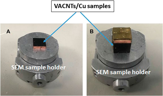
FIGURE 1. (A) Top view setup for VACNT layer surface morphology. (B) Side view setup for VACNT layer thickness.
Vertically Aligned Carbon Nanotubes Layer Surface Modification
Owing to its intrinsic structure and the high packing density of the VACNT layer, the main issue faced in the fabrication of VACNT-based MNC is the low wettability of CNTs with the molten metal matrix fill. To overcome this problem, in this study, the surface modification techniques were introduced for the objective of enhancing overall attachment between the VACNT layer and matching substrate. The different methods including plasma (South bay Technologies RIE-2000), sputter coating (Denton DV502A), and a combination of plasma and sputter coating were selected to modify the VACNT layer surface to improve CNT surface wettability while maintaining the alignment of VACNTs. The time of plasma treatment and the thickness of the metal layer were varied to find the optimum conditions for surface modification of the VACNT layer. Before and after surface modification, the VACNT layer surface morphology/structure was characterized by SEM. The results will be discussed in the next section.
Fabrication of Vertically Aligned Carbon Nanotubes-Based Metal Nanocomposite as Thermal Interface Material
Based on VACNT/Cu sample, a three-layer “sandwich” structure (Cu/TIM/Substrate) was created to make the VACNT-based MNC as TIM and processing scheme can be seen in Figure 2. The material and size/thickness of each layer on sandwich sample was shown in Table 1.
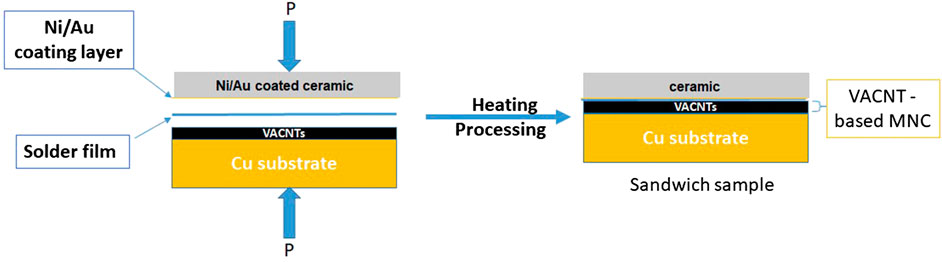
FIGURE 2. Sandwich sample fabrication process and configuration.
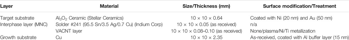
TABLE 1. Sample preparation materials.
To reach the aforementioned goal, a new soldering setup was developed by converting a Thermo-Electric Generator (TEG) test stand into a Heated Compression System shown in Figure 3. A sandwich sample, produced by attaching a thin ceramic (0.64 mm) substrate (coated with a 20 nm nickel and 50 nm gold bi-layer) to a VACNT/Cu sample using selected 241 solder (10 × 10 mm), was first placed into a custom Macor sample holder (see Figure 3) and then delivered the holder to the HCS. A developed optimum processing, as Table 2 shown, was used to fabricate the VACNT based MNC interphase in a three-layer “sandwich” sample. The desired temperatures and load pressures are monitored/controlled using a custom LabVIEW program; a nitrogen purge capability was added to ensure the copper does not oxidize at high temperatures. Using metal coated ceramic substrates, solder241 and VACNT/Cu samples (with/without VACNT layer surface modification), a series of sandwich samples were produced by HCS (Figure 3) under the optimized processing conditions (Table 2). The structure of sandwich and morphology of interphase (MNC) in sandwich sample was characterized by SEM and will be discussed in next section.
FIGURE 3. Heated Compression System (HCS) for “sandwich” structure MNC fabrication and sample holder with sample in-place (Right bottom).
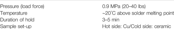
TABLE 2. Optimized parameters for VACNT based MNC fabrication (HCS).
Vertically Aligned Carbon Nanotubes/Solder Interphase (Metal Nanocomposite) Thermal Analysis and Stability Testing
The thermal diffusivity of the VACNT/solder nanocomposite interphase layer was conducted by utilizing the Netzch Laser Flash Apparatus 457 (LFA) with the goal of characterizing thermal properties and evaluating thermal performance/stability. In this study, a series of three-layer sandwich samples, made with different treatments on the surface of the VACNT layer (plasma, sputtering, etc.), were tested. Each sample was tested at least three times in alternating tray positions with a one-dimensional heat flux at temperature steps of 25, 50, 100, and 150°C. For three-layer structure samples, the Cu (bottom) and ceramic (top) substrates are programmed as known layers with a constant thickness and density; as the unknown layer, the thickness of VACNT based MNC was measured with SEM. The standard heat-loss (minus contact resistance) correction model was selected as the best match to determine the correct diffusivity (Firkowska et al., 2011).
The reliability of the VACNT based MNC were evaluated by a custom designed Rapid Thermal Cycling System. All three-layer (Cu/MNC/Ceramic) samples which were already measured in the LFA, were tested. To simulate the conditions that TIMs undergo in the field, the experimental conditions were selected, seen in Table 3. Thermal properties of tested samples were measured/calculated by LFA system again after each set of 50 thermal cycles from −25 to 125°C up to 150 cycles. The thermal stability of interphase was assessed by a percentage increase in the thermal resistance of MNC after thermal cycles. According to a standard approach to testing device failure in electronics, a 50% increase in the thermal resistance of the MNC indicates failure of the sample because this can lead to further degradation of the interface and thermal runaway as the mismatch in thermal expansion becomes worse.
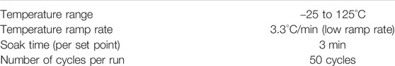
TABLE 3. Parameters of thermal reliability testing (rapid thermal cycling machine).
Results and Discussion
The Morphology of Vertically Aligned Carbon Nanotubes Layer Before and After Surface Modification
As a TIM, the CNT layer structure plays an important role on its thermal and mechanical properties. The VACNT layer with high packing density will increase interface contact area and resulted a good thermal and mechanical performance. SEM images of CNT array synthesized on Cu substrate are shown in Figure 4. The result indicated that, using FCCVD method, a uniform and high dense vertical aligned CNT layer was successfully grown on buffer layer coated Cu foil surface. After plasma or/and sputtering metallization treatment, the surface of VACNT layer has undergone significant changes.
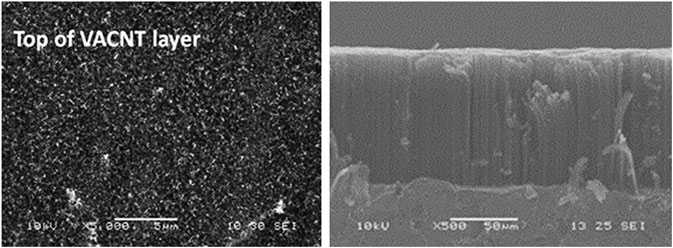
FIGURE 4. SEM images of VACNTs grown on 15 nm Al coated Cu foil substrate. Top view (Left, scale bar = 5 µm) and side view (Right, scale bar = 50 µm).
Vertically Aligned Carbon Nanotubes Layer Surface Plasma Etching
Several CNT/Cu samples were subjected to plasma treatment (H2 as sources) with 5, 10, or 15 min of treating times. The changes on VACNT layer surface morphology before and after treatment as well as the effect of treated time were monitored with SEM, and the results are shown in Figures 5 and 6. Comparing the SEM images before and after plasma etching, in Figure 5, the surface morphology of the VACNT layer obvious changed as expected; when the treatment duration was increased from 5 to 15 min, more “open space” at the top became exposed. There was a visible difference between the 10 and 15 min plasma treatment (see Figure 6): the 10 min treatment tops off between 1 and 2 microns from the surface whereas the 15 min treatment shreds through 2–3 microns from the surface, leaving a much lower density of VACNT layer packing and thus further increasing the solder infiltration surface. This result indicated that the surface morphology of the treated VACNT layer was determined by the time of plasma treatment. There was more open space on the top of the VACNT layer after a long-time processing, which will result in the improved wettability of the CNT array.
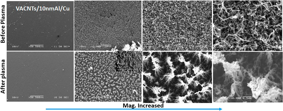
FIGURE 5. Top view SEM images of VACNT layer: before and after 15 min plasma treatment. (Scale bar from left to right = 500, 10, 1.0, 0.5 µm.)
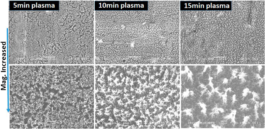
FIGURE 6. Top view SEM images of VACNT layer: comparison of plasma treatment durations. (Scale bar on top = 10 µm; Scale bar on bottom = 1.0 µm).
Vertically Aligned Carbon Nanotubes Layer Surface Metallization
The metallization of both substrate and VACNT layer surface is a promising approach to reduce the thermal contact resistance and simultaneously improve the interfacial adhesion of CNTs/matching substrate. In this study, Ti (Titanium)) and Ni (Nickel) were selected to metalize/modify the VACNT layer surface of VACNT/Cu samples due to their excellent physical properties and good adhesion with CNT (Ti as first layer) and solder (Ni as second layer). The Ti/Ni bi-metal thin layer with different thickness and Ti/Ni ratio were sputter coated on VACNT layer surface of VACNT/Cu samples. SEM images of the VACNT layer surface, before and after metal coating, can be found in Figure 7. These images show that a thin metal layer was evenly covered on the surface of the VACNT layer, which will result in a strong interfacial adhesion between the CNT array and the solder. The sputtering method was also used to coat a Ni/Au (20 nm/50 nm) double-layer thin film onto the surface of ceramic matching substrate to enhance interface properties between VACNT layer and substrate.
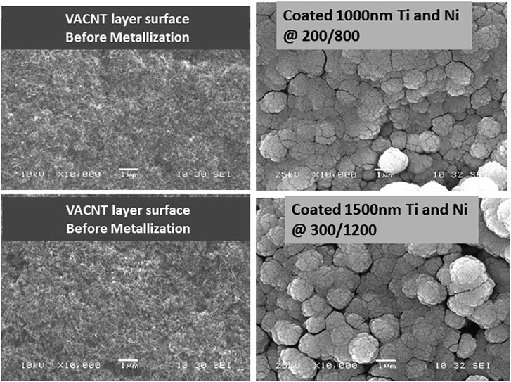
FIGURE 7. Top view of SEM images: the metalized VACNTs surface by Ti/Ni bi-metal layer. (Scale bar = 1.0 µm)
Vertically Aligned Carbon Nanotubes Layer Surface Plasma Treatment and Metallization
Surface metallization and plasma treatment are the two methods of surface modification pursued in this study. Ideally, plasma treatment will promote wettability/solder infiltration and surface metallization will improve surface attachment. Therefore, if these two methods are combined for VACNT layer surface treatment, the best interface performance should be produced. Based on this consideration, the sample processing was performed by coating different thicknesses of Ti/Ni bi-metal layer on the plasma-treated (via H2 for 10 or 15 min) VACNT layer surface. The SEM images of the combined surface treatment samples can be found in Figure 8. The SEM images depict the expected results: open areas on the surface of VACT layer for solder infiltration are covered with a layer of metallic particles.

FIGURE 8. Top view SEM Images. (A) The bi-metal layer with different thickness coated on Plasma treated VACNTs surface (10 min). (B) The bi-metal layer coated on Plasma treated (10 and 15 min) VACNTs surface. Scale bar = 1 µm (A); Scale bar (from left to right) = 1, 50, 1.0, 0.5 µm (B).
Structure of Three-Layer “Sandwich” Sample with Vertically Aligned Carbon Nanotubes-Based Metal Nanocomposite
The structure of sandwich and morphology of interphase (MNC) in sandwich sample was characterized by SEM and shown in Figure 9. SEM images shown a good interface connection between the MNC and the two substrates (ceramic and Cu). The results demonstrated that, with a suitable solder material, the fabrication process of sandwich sample can not only completely attach the matching substrate to the surface of the VACNT layer, but also maintain the interface adhesion of VACNT/Cu (No CNTs peeled from Cu foil). Due to the elastic properties of the VACNT array, the deformation of the VACNT layer can be clearly observed in the SEM image of Figure 9. As a TIM, this deformation should bring MNC good thermal and mechanical performance, especially in terms of thermal reliability.
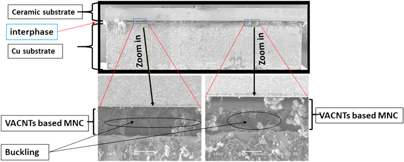
FIGURE 9. Side view of fabricated sandwich sample (top) and MNC interphase (bottom). (Top scale bar = 500 µm; Bottom scale bar = 50 µm).
Thermal Property of Vertically Aligned Carbon Nanotubes-Based Metal Nanocomposite in Sandwich Sample
Thermal property analysis for the MNC interphase of Cu/MNC/Ceramic samples focused on LFA testing to calculate the thermal resistance of the VACNT/solder interphase layer. All qualified three-layer sandwich samples, including with and without VACNT layer surface modification, were tested. Thus, the following results and discussion section focused on how the thermal properties of the MNC interphase were influenced by the method of VACNT layer surface treatment. Specifically, the thermal resistance was calculated based on the thermal diffusivity measured at 100°C by Eq. 1, where L is the VACNT layer thickness, α is the measured diffusivity, ρ is the VACNT layer density and Cp is the specific heat of the CNTs set to a constant of Cp = 0.8.
To minimize error, numerous samples (grouped by VACNT layer surface treatment method) were tested. The average thermal resistance of each group samples, with standard deviation, can be found in Figure 10. These results will be discussed based on the VACANT layer surface treatment method.
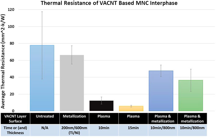
FIGURE 10. Thermal resistance of MNC sandwich samples, per category of surface modification.
From test results in Figure 10, the following conclusions about the effect of VACNT layer surface modification on the thermal resistance of the interphase (Cu/VACNT-solder/Ceramic sample) were drawn:
(1) The thermal resistance of MNC interphase was clearly influenced by surface treatment of VACNT layer. The changes of interface contact area, infiltration space and CNT surface wettability after surface treatment are the main reasons for this result.
(2) The thermal resistance of all samples made of untreated VACNT layers varied greatly (a large standard deviation). The main reason is most likely due to the uncertainty of the surface structure (morphology/purity, etc.) with untreated VACNT layer (as received). These variations will cause actual the interface contact area between the VACNT layer and matching substrate to be different varying for each untreated sample, thereby resulting in different thermal resistance values.
Compared to surface modified VACNT layer, the sample made with surface unmodified VACNT Layer had the highest thermal resistance value (see Figure 10). Namely, without VACNT layer surface modification, there is a large interface resistance between VACNT layer and matching substrate although fabrication techniques were optimized. This issue is primarily caused by the lack of solder infiltration within the VACNT layer during fabrication processing due to the CNTs low wettability and dense surface (non-aligned) of VACNT layer.
Surface metallization promotes improved adhesion (wettability) for contact between the CNT array tips and solder. Improved interfacial adhesion, where the thickness of metallization layer plays an important role, establishes a better connection, and thus resulted in improved thermal and mechanical properties. In this study, the interfacial mechanical properties (including the tensile strength and shear strength) of sandwich samples were explored by pull-off (tensile) and shear test. The results indicated that, when an 800 nm bi-metal thin layer (200 nm Ti layer and then 600 nm Ni layer) was coated on VACNT layer surface, a strong tensile strength was produced in the interface between VACNT layer and matching substrate. Therefrom, the 800 nm bi-metal layer was applied for all VACNT layer surfaces metallization. It can be clearly seen in Figure 10 that MNC interphase thermal resistance was reduced by VACNT surface metallization. Adding conducting film/particles to the VACNT layer surface to enhance adhesion between CNT-solder are main reason for this improvement. However, an average thermal resistance of 66 mm2-K/W means that surface metallization does not significantly improve the interphase thermal resistance. This is most likely due to the small penetration space for solder on the surface of the metalized VACNT layer.
VACNT layer surface plasma treatment was applied to improve the overall wettability of the CNT surface and opened space to enhance solder infiltration during MNC fabrication. Compared to the reference of VACNT based MNC (untreated) thermal resistance, the results as shown in Figure 10 demonstrated a significantly lower thermal resistance with surface plasma modified VACNT/solder interphase (between two substrates). Specifically, samples which were treated by 15 min H2 plasma had the lowest thermal resistances with a small standard deviation, as well as a greater improvement compared to sample made of 10 min H2 plasma treated VACNT layer. The reasonable explanation for this result is that the longer treatment time can create more space on VACNT layer surface as shown in Figure 6, and this would allow more solder to infiltrate into the VACNT array during three layer sample fabrication to produce a stable MNC interface.
VACNT layer surface plasma treatment followed by surface metallization processing were expected to enhance the interfacial adhesion of CNT tip and solder while providing more infiltration space to improve thermal properties and reliability of the VACNT based MNC as TIM. The experimental results in Figure 10 indicated that the surface modification of the VACNT layer by a combination technique (plasma and metallization) did reduce the thermal resistance of the VACNT based MNC interphase compared to the original (untreated samples). The pull-off testing results also show a strong interfacial adhesion between the modified VACNT surfaces and matching substrate. Under the same metallization conditions (metal layer Ti/Ni = 200 nm/600 nm), the VACNT surface after 15 min of H2 plasma treatment produced a lower MNC interphase thermal resistance than that with 10 min of H2 plasma treatment. However, this value is much higher than that of samples made with VACNT layer treated by plasma only. This is because the metal layer/particles coated on plasma treated VACNT surface (see Figure 8) may prevent solder infiltrating into the VACNT layer during MNC fabrication processing.
Thermal Performance/Reliability of Vertically Aligned Carbon Nanotubes-Based Metal Nanocomposite in Sandwich Sample
Although reducing the overall thermal resistance is a primary goal of this study, practical applications will cause periodic thermal stresses during normal operations. Thus, reliability testing is necessary to characterize the thermal and mechanical performance of three-layer samples being created with VACNTs based nanocomposite (as TIM). In this study, the reliability of the VACNT-based MNC was evaluated as the percent increase in VACNTs/solder interphase thermal resistance from the original value through nominally induced thermal stress (thermal cycling). Using the aforementioned procedure and equipment related to reliability testing, all three-layer samples were subjected to 150 thermal cycles from −25 to 125°C. The thermal performance of the samples was retested by LFA after each set of 50 thermal cycles. The thermal resistance (including the results before and after the thermal cycle) and the nominal percentage increase (original value as reference) in thermal resistance after each set of 50 thermal cycles were illustrated in Figure 11 and Table 4, respectively, by surface treatment category as below.
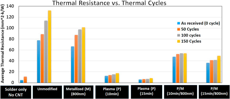
FIGURE 11. Thermal cycles vs. thermal resistance of VACNT-based MNC as thermal interphase.
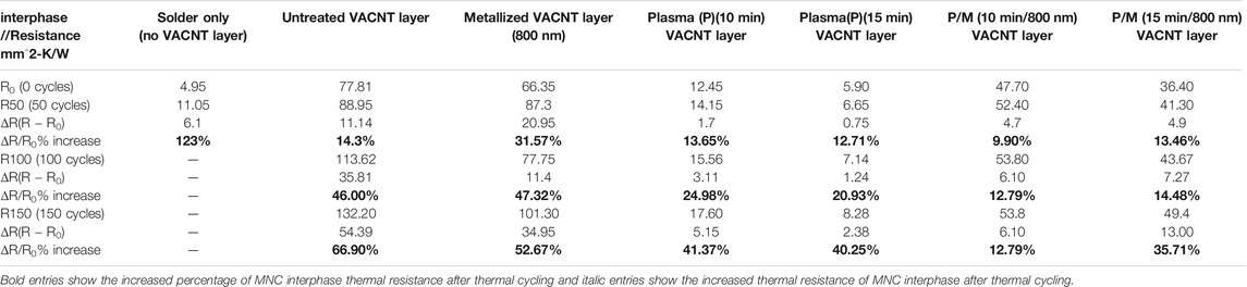
TABLE 4. The effect of thermal cycles on thermal resistance (average) of TIM.
To compare the thermal properties of VACNT-based MNC and conventional TIM (solder), the Cu/Solder/Ceramic three-layer sandwich samples were prepared and tested. As expected, the solder-only TIM produced the lowest value of thermal resistance (good thermal conductivity) but quickly loses its reliability (very poor interfacial tensile strength) after only 50 thermal cycles, and the thermal resistance was significantly increased by more than 100% as shown in Figure 11 and Table 4. As compared, the sandwich samples made of unmodified VACNT layer produced a more reliable VACNT-based TIM, which showed the lower rate of increase in thermal resistance after thermal cycles as seen in Figure 11 and Table 4. However, the overall performance of these samples was not satisfactory due to their high thermal resistance.
Related to reliability during thermal cycling, all sandwich samples made with surface modified VACNT layer were tested. As expected, thermal resistance of MNC interphase for all tested samples increased after each thermal cycling test. However, the samples which have the VACNT surface modified, except for the samples with surface metallization treatment, showed modest increases in thermal resistance when compared to samples which have not, especially after 100 cycles. Except the surface metallized samples, all samples made with surface modified VACNT layer demonstrated improved interphase thermal stability, resulting in the thermal resistance increased by less than 50% (failure point) even after 150 thermal cycles. Moreover, the samples made with both plasma treated and metalized VACNT layer demonstrated the best thermal stability by showing a 12.79% increase on thermal resistance after 150 thermal cycles. The good thermomechanical performance under continued stresses was attributed to 1) opened veins/space (plasma treatment) on the VACNT array for solder infiltration; 2) metal particles (metallization) to promote the wettability of CNT tips to form a strong interfacial adhesion of VACNT layer and solder.
Conclusion
In this study, a VACNT layer was synthesized directly onto Cu foil substrate by FCCVD method. In order to achieve better interfacial adhesion of VACNT-based MNC (as TIM), a VACNT layer surface post-processing procedure (including plasma treatment and metallization) was developed to improve the solder infiltration onto VACNT layer and thereby improve the overall thermal performance of interphase. The effect of different post-processing techniques on VACNT layer surface and interfacial properties of VACNTs/matching substrate were explored. The thermal performance of MNC were evaluated via Laser Flash system and Rapid Thermal Cycling System. Overall experimental results demonstrated:
(1) The VACNT layer surface modification is an effective method to improve thermal properties of VACNT based MNC as TIM. Compared with surface untreated VACNT layer, all the surface modified VACNT layer (as TIM) showed lower thermal resistance and higher thermal stability in tested sandwich samples.
(2) Among different VACNT surface modification methods, the plasma treated (especially with 15 min) VACNT layer surface promoted the best thermal properties of MNC, which was manifested by the lowest thermal resistance (5.90 mm2-k/W, close to tested solder value 4.95 mm2-k/W) and high thermal reliability under the thermal cycling test.
(3) Compared with the untreated VACNT layer, the 15 min plasma treated VACNT layer can reduce the thermal resistance of VACNT-based MNC by more than 80%. This finding indicated that CNT surface plasma treatment is a promising technique to enhance interfacial connection between CNT layer and solder to produce a good performance of VACNT based MNC as TIM.
(4) The sample, made with a VACNT layer surface treated by both plasma and metallization, showed an improved thermomechanical performance under thermal cycling. This is because the improved infiltration and wettability of solder by opened veins/holes and coated particles on VACNT array which promote interfacial adhesion and thermal conductivity, thereby maintaining the thermal performance under continued stresses.
Data Availability Statement
The raw data supporting the conclusions of this article will be made available by the authors, without undue reservation.
Author Contributions
QZ is a main author, all others are equal. All authors contributed to manuscript revision, read, and approved the submitted version
Funding
Air Force Office of Scientific Research for funding support.
Conflict of Interest
The authors declare that the research was conducted in the absence of any commercial or financial relationships that could be construed as a potential conflict of interest.
Acknowledgments
The authors would like to thank the Air Force Office of Scientific Research for funding support, the Air Force Research Laboratory/RQQM, and following people for their help on this project: John Murphy, Jacob Lawson, Ammon Williams, James Scofield, William Lanter, and Joseph Merrett.
References
Barako, M., Yuan, G., Marconnet, A., Asheghi, M., and Goodson, K. (2012). “Solder-bonded carbon nanotube thermal interface materials,” in Proceedings of 13th IEEE intersociety conference: thermal and thermomechanical phenomena in electronic systems (iTherm), San Diego, CA, May 30–June 1, 2012, 1225–1233. doi:10.1109/ITherm18282.2012
Berber, S., Kwon, Y.-K., and Tománek, D. (2000). Unusually high thermal conductivity of carbon nanotubes. Phys. Rev. Lett. 84, 4613–4616. doi:10.1103/physrevlett.84.4613
Che, J., Çagin, T., and Goddard, W. A. (2000). Thermal conductivity of carbon nanotubes. Nanotechnology 11, 65–69. doi:10.1088/0957-4484/11/2/305
Chen, H., Roy, A., Baek, J.-B., Zhu, L., Qu, J., and Dai, L. (2010). Controlled growth and modification of vertically-aligned carbon nanotubes for multifunctional applications. Mater. Sci. Eng. R Rep. 70, 63–91. doi:10.1016/j.mser.2010.06.003
Chu, K., Guo, H., Jia, C., Yin, F., Zhang, X., Liang, X., et al. (2010). Thermal properties of carbon nanotube-copper composites for thermal management applications. Nanoscale Res. Lett. 5, 868–874. doi:10.1007/s11671-010-9577-2
Cola, B., Hodson, S., Xu, X., and Fisher, T. (2008). “Carbon nanotube array thermal interface enhanced with paraffin wax,” in Proceedings of the ASME summer heat transfer conference, August 10–14, 2008, Jacksonville, FL, HT2008–56483.
Cola, B. A., Xu, J., Cheng, C., Xu, X., Fisher, T., Fisher, T. S., et al. (2007). Photoacoustic characterization of carbon nanotube array thermal interfaces. J. Appl. Phys. 101 (5), 054313. doi:10.1063/1.2510998
Cross, R., Cola, B. A., Fisher, T., Xu, X., Gall, K., and Graham, S. (2010). A metallization and bonding approach for high performance carbon nanotube thermal interface materials. Nanotechnology 21, 445705. doi:10.1088/0957-4484/21/44/445705
Firkowska, I., Boden, A., Vogt, A.-M., and Reich, S. (2011). Effect of carbon nanotube surface modification on thermal properties of copper-CNT composites. J. Mater. Chem. 21 (43), 17541–17546. doi:10.1039/c1jm12671g
Ganguli, S., Reed, A., Jayasinghe, C., Sprengard, J., Roy, A. K., Voevodin, A. A., et al. (2013). A simultaneous increase in the thermal and electrical transport in carbon nanotube yarns induced by inter-tube metallic welding. Carbon 59, 479–486. doi:10.1016/j.carbon.2013.03.042
Ganguli, S., Roy, A. K., Wheeler, R., Varshney, V., Du, F., and Dai, L. (2012). Superior thermal interface via vertically aligned carbon nanotubes grown on graphite foils. J. Mater. Res. 28, 933. doi:10.1557/jmr.2012.401
Hu, X. J., Padilla, A. A., Xu, J., Fisher, T. S., and Goodson, K. E. (2006). 3-Omega measurements of vertically oriented carbon nanotubes on silicon. ASME J. Heat Transfer. 128, 1109–1113. doi:10.1115/1.2352778
Huang, H., Liu, C. H., Wu, Y., and Fan, S. (2005). Aligned carbon nanotube composite films for thermal management. Adv. Mater. 17, 1652–1656. doi:10.1002/adma.200500467
Kim, P., Shi, L., Majumdar, A., and McEuen, P. (2001). Thermal transport measurements of individual multiwalled nanotubes. Phys. Rev. Lett. 87, 2155021. doi:10.1103/physrevlett.87.215502
Lin, W., Olivares, V., Liang, Q., Zhang, R., Moon, K., and Wang, C. (2009). “Vertically aligned carbon nanotubes on copper substrates for applications as thermal interface materials: from synthesis to assembly,” in 9th IEEE conference on nanotechnology, Genoa, Italy, July 26–30, 2009. doi:10.1109/ectc.2009.5074051
Panzer, M., Zhang, G., Mann, D., Hu, X., Pop, E., Dai, H., et al. (2008). Thermal properties of metal-coated vertically-aligned single-wall nanotube arrays. J. Heat Transfer. 130, 052401, 2008. doi:10.1115/1.2885159
Son, Y., Pal, S., Borca-Tasciuc, T., Ajayan, P., and Siegel, R. (2008). Thermal resistance of the native interface between vertically aligned multiwalled carbon nanotube arrays and their SiO2/SiSiO2/Si substrate. J. Appl. Phys. 103, 024911. doi:10.1063/1.2832405
Tong, T., Zhao, Y., Delzeit, L., Kashani, A., Meyyappan, M., and Majumdar, A. (2007). Dense vertically aligned multiwalled carbon nanotube arrays as thermal interface materials. IEEE Trans. Comp. Packag. Technol. 30, 92–100. doi:10.1109/TCAPT.2007.892079
Wang, H., Feng, J., Hu, X., and Ng, K. M. (2007). Synthesis of aligned carbon nanotubes on double-sided metallic substrate by chemical vapor deposition. J. Phys. Chem. C 111, 12617–12624. doi:10.1021/jp0730848
Xu, J., and Fisher, T. S. (2006). Enhancement of thermal interface materials with carbon nanotube Arrays. Int. J. Heat Mass Tran. 49, 1658–1666. doi:10.1016/j.ijheatmasstransfer.2005.09.039
Yang, D., Zhang, Q., Chen, G., Yoon, S., Ahn, J., Wang, S., et al. (2002). Thermal conductivity of multiwalled carbon nanotubes. Phys. Rev. B 66, 165440. doi:10.1103/physrevb.66.165440
Yin, X., Wang, Q., Lou, C., Zhang, X., and Lei, W. (2008). Growth of multi-walled CNTs emitters on an oxygen-free copper substrate by chemical-vapor deposition. Appl. Surf. Sci. 254 (20), 6633–6636. doi:10.1016/j.apsusc.2008.04.040
Keywords: vertical aligned carbon nanotubes, plasma, sputtering, metallization, thermal resistance, metal nanocomposite, laser flash testing
Citation: Zhang Q, A. Calderon B, R. Ebbing C, J. Elston L, W. Byrd L and Tsao B-H (2020) Thermal Properties Enhancement of Vertically Aligned Carbon Nanotubes-Based Metal Nanocomposites as Thermal Interface Materials. Front. Mater. 7:572956.
Received: 15 June 2020; Accepted: 28 September 2020;
Published: 28 October 2020.
Edited by:
Ruixin Zhu, Tongji University, ChinaReviewed by:
Che Azurahanim Che Abdullah, Putra Malaysia University, MalaysiaImad Arfaoui, Université Pierre et Marie Curie, France
Copyright © 2020 Zhang, Calderon, Ebbing, Elston, Byrd and Tsao. This is an open-access article distributed under the terms of the Creative Commons Attribution License (CC BY). The use, distribution or reproduction in other forums is permitted, provided the original author(s) and the copyright owner(s) are credited and that the original publication in this journal is cited, in accordance with accepted academic practice. No use, distribution or reproduction is permitted which does not comply with these terms.
*Correspondence: Qiuhong Zhang, qiuhong.zhang.3.ctr@us.af.mil