Research on Microhole Processing Technology Based on the Femtosecond-Laser Spiral Trepanning Method


1
School of Aerospace Engineering, Xiamen University, Xiamen 361005, China
2
Zhejiang Provincial Engineering Lab of Laser and Optoelectronic Intelligent Manufacturing, Wenzhou University, Wenzhou 325035, China
3
Xi’an Institute of Optics and Precision Mechanics, Chinese Academy of Sciences, Xi’an 710119, China
*
Author to whom correspondence should be addressed.
Appl. Sci. 2020, 10(21), 7508; https://doi.org/10.3390/app10217508
Submission received: 26 September 2020
/
Revised: 12 October 2020
/
Accepted: 20 October 2020
/
Published: 26 October 2020
(This article belongs to the Section Applied Industrial Technologies)
Abstract
:Featured Application
Film hole; fuel injection nozzle; microfluidic chips.
Abstract
Microholes have crucial applications in aerospace, the automotive industry, and other industries. In this study, the microhole processing technology based on the femtosecond-laser spiral trepanning method was investigated. By adjusting the spiral scanning path, laser power distribution, and defocusing amount to control laser energy distribution, an inverted cone hole, straight hole, and normal cone hole were obtained finally. The morphology and element of the microhole were investigated by scanning electron microscopy (SEM) equipped with energy-dispersive X-ray spectroscopy (EDX). The experimental results of the femtosecond-laser spiral trepanning method could achieve fewer impurities. Finally, the formation mechanisms of different microholes are explained in detail. The method is simpler and more efficient than the traditional microhole processing technology. The femtosecond-laser spiral trepanning method with controllable hole roundness, accuracy, and taper has important practical significance in microhole processing.
1. Introduction
With the development of the aerospace industry, increasing the inlet temperature of the turbine is the most effective way to achieve a high thrust-to-weight ratio of new aero-engines [1,2]. Therefore, it is necessary to machine film holes on the blade to cool and isolate the blade. By varying the size and taper of the film holes, the flow characteristics of the turbine can be changed to produce different film cooling effects [3]; therefore, the machining of film holes with different tapers has always been a key technology for machining aero-engine turbine blades. Besides, in the fuel injection structure, the micro-hole cone in the fuel injection nozzle has a very important influence on fuel atomization [4]. Microholes play an important role not only in the aviation [5] and automotive [6] industries but are also relevant to the field of microfluidics, where they are used in microfluidic chips [7], electronics [8], biomedicine [9], and other fields [10]. Therefore, it is of great significance to realize the controllable roundness, accuracy, and taper machining technology for engineering applications.
At present, the main microhole machining methods include electrochemical machining [11,12], electrical discharge machining [13,14], electron-beam machining [15], ultrasonic machining [16], and ion-beam processing [17]. However, comparing with femtosecond-laser machining [18,19], the electrochemical machining, electrical discharge machining and ultrasonic machining are complex to process microholes of different sizes and tapers. Besides, electron-beam machining is extremely expensive. Therefore, electron-beam machining is not suitable for practical industrial applications.
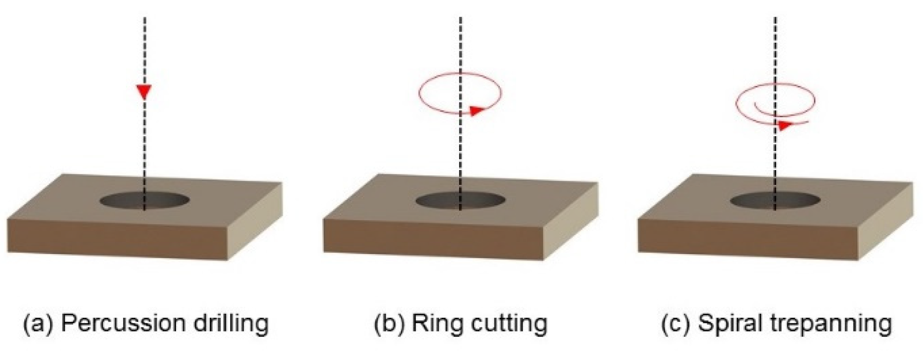
The commonly used laser microhole processing methods are mainly divided into three categories (Figure 1): percussion drilling [20], ring cutting [21], and spiral trepanning [22]. In percussion drilling, the laser is directly focused on the material to make impact. Here, the hole type and accuracy depend on the beam quality after focusing, and the microhole depth-to-diameter ratio is not high; thus, it is difficult to process deep holes; moreover, the aperture needs to be adjusted to adjust the focusing lens and laser power, and the molten material can easily accumulate near the microhole, resulting in poor processing quality. For example, Park et al. [23] used a femtosecond laser to perform impact drilling experiments on a copper surface, and many recast layers and impurities occurred around the microholes. The method is difficult to achieve microholes of different sizes and tapers. The second method, ring cutting, involves repeatedly scanning the sample along a circular path; however, with the increase in the cutting depth, removing the material becomes increasingly difficult, which can lead to the repeated heating of the surface chip and the subsequent formation of a recast layer and a heat-affected zone. Wang et al. [22] achieved annular drilling on K24 superalloy by femtosecond-laser processing, and the results showed that significant impurities occurred around the microholes. Besides, the ring cutting method cannot process different taper microholes. The third method, spiral trepanning, involves moving the focused spot scan along a certain trajectory, using an optical system. The spiral trepanning is conducted from the inside to the outside, and the material is removed step by step from the top to the bottom. The heat-affected zone and the recast layer are also smaller than those of the other processes, which can achieve the accurate control of the microhole size. The advantage of this method is the highly precise control of the hole diameter. The hole size can be arbitrarily adjusted, and a high depth-to-diameter ratio can be achieved. Wang et al. [22] also achieved spiral trepanning on K24 superalloy by femtosecond-laser processing, and the quality of microholes had been greatly improved. However, the method could not achieve inverted an cone hole.
Therefore, in this study, femtosecond-laser spiral trepanning was used to process microholes. By varying the path of spiral scanning and laser power, microhole with different tapers can be realized. Meanwhile, the roundness, accuracy, and taper of microholes can be controlled. To achieve a larger taper, the defocusing amount was investigated. The experimental results showed that the method is viable. Compared with the previously reported method [11,12,13,14,15,16,17,21,22,23], the femtosecond-laser spiral trepanning method is very simple and highly efficient for processing different taper microholes. Besides, the formation mechanism of different microholes is also explained in this paper.
2. Experimental Setup
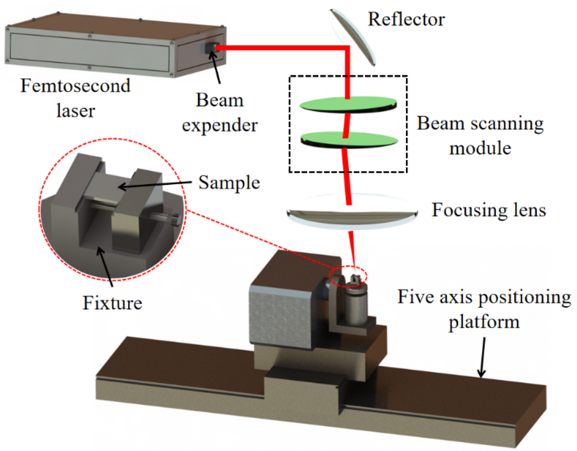
The femtosecond-laser processing equipment used in the experiment (Figure 2) mainly included a femtosecond laser, reflector, beam-scanning system, focusing lens, and five-axis positioning platform. The model of the femtosecond laser was Light Conversion l17771, which emits a wavelength of 1064 nm with the maximum average power of 20 W at 30 kHz repetition rate and a pulse width of 200 fs. The focusing spot diameter was 20 μm. The beam scanning module was mainly composed of two wedges (Figure 2), which were used to control the laser beam scanning path. The motion accuracy of the PI platform was 1 μm. The air pressure is set to 0.3 Pa. The sample size was 40 × 40 × 2 mm2 of 304 stainless steel. The sample was fixed on the fixture, which was installed on the five-axis positioning platform. All experiments were carried out in a clean room and at constant temperature.
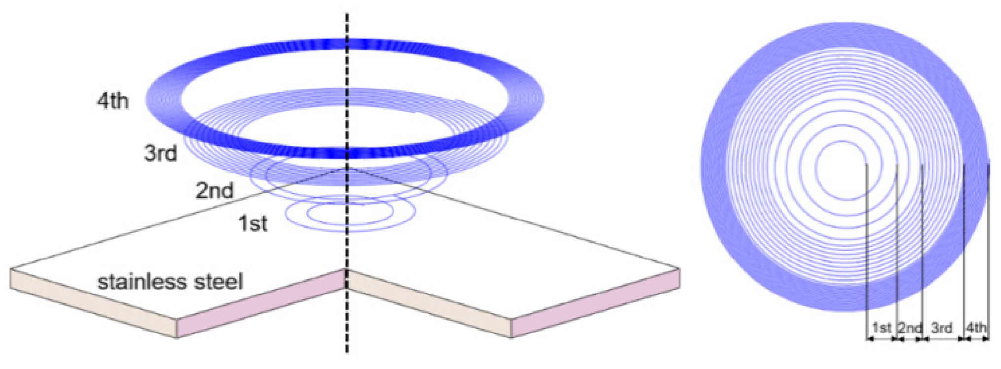
First, we mainly studied the influence of the increment of radius angle, the number of circles, and the power of each circle on microhole machining. Before laser processing, the sample was immersed in ethanol for 10 min for ultrasonic cleaning and impurities removal; then, the sample was taken out to dry. The specific laser parameters were as follows: the laser scanning speed was 2400 mm/s, the starting angle was adjusted to 3° through the wedge, and each layer was scanned for 4 cycles. The laser power of the first cycle was 45%, the increment of radius angle was 1.1°, and the number of circles was 2. The laser power of the second circle was 50%, the increment of radius angle was 0.8°, and the number of circles was 2. The laser power of the third circle was 55%, the increment of radius angle was 0.3°, and the number of circles was 10. The laser power of the fourth circle was 60%, the increment of radius angle was 0.1°, and the number of circles was 18. After the first layer was scanned, the vertical feed was adjusted to 0.01 mm (the Z-axis was adjusted by the five-axis motion platform to make the laser focus drop by 0.01 mm), and the number of feeding layers was adjusted according to the material thickness, with the maximum of 400 layers. The microhole diameter was determined by the incident beam deflection angle and the focal length f of the focusing lens, and the corresponding relationship is D = d + d0 = 2F · tan θ + d0, where D is the processing aperture, d is the scanning diameter of the spot, F is the focusing lens focal length, θ is the deflection angle between the beam incident to the focusing lens and the focusing lens optical axis, and d0 is the laser spot diameter. The schematic diagram and trajectory of laser spiral scanning are shown in Figure 3. Finally, an inverted cone hole with an entrance diameter of 0.30 ± 0.01 mm and an exit diameter of 0.35 ± 0.01 mm was required to be machined on a 2-mm-thick stainless steel sample.
3. Results and Discussion
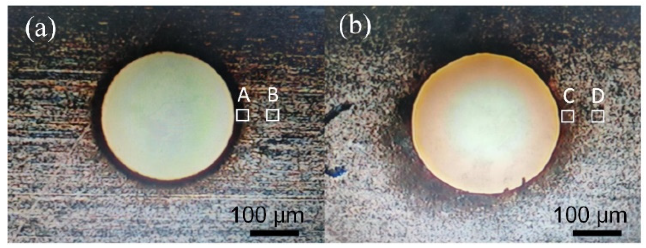
The microholes of a femtosecond laser–processed stainless steel are displayed in Figure 4. The average diameters of the microhole entrance and exit were 0.3056 and 0.3524 mm, respectively. Meanwhile, there was almost no slag at the microhole entrance after processing (Figure 4a). However, due to the thermal effect, a circle of black oxide was formed on the surface near the microhole entrance, mainly because the outer ring of the laser scanning path was relatively dense and the power was relatively large. Shi et al. [24] found that in microhole drilling via laser trepanning, the oxygen amount decreased with further movement away from the microhole entrance. Figure 4b is a microscopic picture of the microhole exit in this study. No obvious slag occurred at the exit after processing, but a small amount of debris existed in the lower right corner. Moreover, the black oxide circle around the microhole exit was larger than that around the microhole entrance, but the oxide color around the exit was relatively light. The mass ratios of different elements observed by energy-dispersive X-ray spectroscopy (EDX) are presented in Table 1. In the table, A and C denote areas near the microhole, while B and D are areas away from the microhole, about 100 μm from A and C. The oxygen mass ratios of areas A and C (6.35% and 6.32%, respectively) were higher than those of areas B and D (5.17% and 5.07%, respectively), which proves the above explanation. In addition, the main reason for the difference in black oxide area between the microhole entrance and exit was that the air pump could blow away the debris and reduce the surface temperature, but with the increase in the laser processing depth, a small amount of residual debris occurred at the inner wall and back surface of the microhole exit. Moreover, an oxide layer was generated on a relatively large area of the microhole exit, due to the poor slag-discharge quality and the continuous accumulation of temperature. By simultaneously studying the morphology of the microhole and the mass ratio of different elements, it is possible to have a more comprehensive understanding of the effect of femtosecond laser processing of the microhole than simply observing the surface morphology of the microhole [22].
The error of the average entrance and exit diameters of the microholes processed by this spiral machining method was less than 6 μm, and the precision of the micro-holes is higher than that previously reported [21,22,23]. Roundness and taper are important indexes to estimate the microhole quality. The maximum and minimum diameters of the microhole entrance were 0.3082 mm and 0.3012 mm, respectively. The maximum and minimum diameters of the microhole exit were 0.3600 mm and 0.3364 mm, respectively.
Therefore, the microholes roundness can be calculated as follows:
The microholes taper can be calculated as follows:
where and are the roundness at the microhole entrance and exit, respectively; is the taper of the inverted cone hole; D is the microhole entrance diameter; d is the microhole exit diameter; and L is the material thickness. The roundness and taper of micro-holes can be obtained by the above formula. It can be found that the entrance had a smaller circularity than the exit; this was mainly because the air pump could blow debris at the microhole entrance and reduce the surface temperature; therefore, the inner hole wall and the exit had a higher amount of debris and temperature than the entrance, which caused the difference in circularity between the entrance and exit. Finally, the microhole taper angle was obtained as 1.34°.
To analyze the microhole formation process, the micromorphology of the whole inverted cone hole was observed by adjusting the number of feeding layers during femtosecond-laser processing. The scanning electron microscopy (SEM) images of feeding layers 2, 4, 10 and 50 are shown in Figure 5. With the increase in the feeding layers, the taper of the inverted cone hole was gradually formed. From the path distribution and energy distribution of the spiral scanning, it can be seen that the number density of the inner ring was small, and the laser energy was relatively low; however, the number density of the outer ring was high, and the laser energy was high. It can be observed that when the laser processing started, the inner ring etching trace was relatively shallow, and the outer ring etching depth was relatively deeper. As the depth increased, the depth difference between the inner and outer circles also increased. Moreover, with the increase in the number of feed layers, the hole depth gradually increased, and the energy increased gradually in the outer ring will diffuse to the outer ring. Therefore, the energy of the outer ring presented a gradient change between the initial front processing and the complete processing of the microhole. This change in the energy gradient caused the formation of the microhole taper. In addition, the low laser-scanning speed can result in higher-quality and more symmetrical holes than a high scanning speed [25]. However, low scanning speed results in a low machining efficiency; therefore, it is necessary to improve the scanning speed to meet the requirements of microholes machining.
Furthermore, we also explored microholes with different tapers formed under different scanning trajectory parameters. We obtained the scanning parameters of microholes with taper angles of 0.03° and 3.09° formed under different scanning paths and power distributions (Table 2). The air pressure is set to 0.3 Pa. The microhole taper size was mainly controlled by changing the laser scanning path and power. In the scanning paths of the normal cone hole, the inner ring was dense and the energy was high, while the outer ring was sparse and the energy was low. In contrast, in the scanning paths of the straight hole and the inverted cone hole, the inner ring was sparse and the energy was small, while the outer ring was dense and the energy was high. The most important thing is that the taper of the microhole is controllable. Besides, compared with the microhole that Wang et al. [22] used femtosecond-laser spiral trepanning processing on, K24 superalloy, the microholes have a high level of precision.
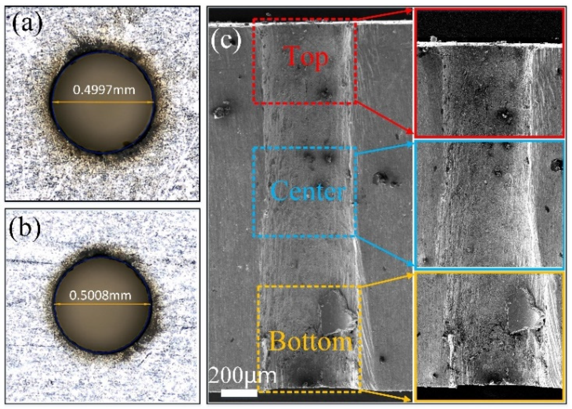
The microhole images obtained by the experimental parameters in Table 2 are shown in Figure 6 and Figure 7. The microhole was relatively round, but there was a certain deviation at the microhole exit (Figure 6a,b), which was mainly due to the influence of slag discharge on the microhole at the exit. We observed the microstructure of the inner wall of the microholes to further understand the processing quality of the microholes. As shown in Figure 6c, no obvious metal residue and molten substance formation occurred at the top, center, and bottom of the inner wall surface after femtosecond-laser processing. Moreover, no obvious processing traces occurred on the inner wall after laser processing. In addition, the mass ratios of different elements at the top, center, and bottom of the microhole cross section are presented in Table 3. The mass ratios of carbon and oxygen decreased from the microhole top to bottom; this may be because the stainless steel surface temperature was relatively low at the beginning. When the laser suddenly heats up, the oxygen in the air will quickly react with the high-temperature stainless steel surface to produce black oxide. With the increase in the processing depth, the stainless steel surface temperature tends to be stable. The oxygen and carbon dioxide contents in the microhole were also relatively low and thus could not easily oxidize the high-temperature stainless steel surface. Therefore, with an increase in the microhole depth, the carbon and oxygen contents on the microhole inner wall gradually decreased.
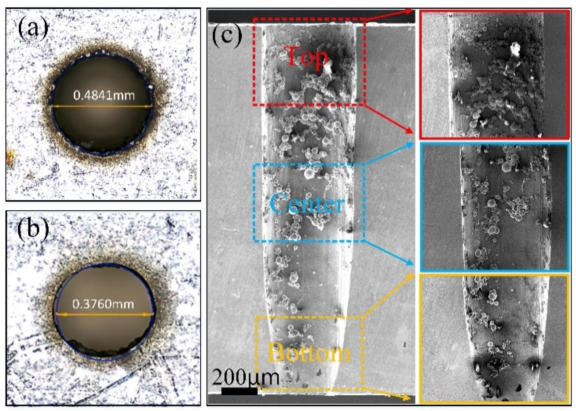
The entrance and exit of the micro-hole with a taper of 3.09° are displayed in Figure 7a,b. The entrance and exit surfaces were slippery, but black oxide existed close to the microhole owing to the laser processing the stainless steel. The microhole cross section (Figure 7c) shows that the microhole was not a full normal cone hole. The walls of the microhole top and center were vertical, and the taper was gradually formed at the bottom. This was because the energy gradually accumulated to the threshold value of stainless steel at the microhole top and center. However, the microhole bottom was tapered, because the laser energy inside the microhole was higher than that outside, and the energy penetrated the stainless steel without removing the outer material of the microhole. Figure 7 shows that the microhole top, center, and bottom had some impurities covering the inner wall; however, the inner wall was smooth where there were no impurities. Thus, we infer the impurities were sputtered material on the inner wall, not molten material of the inner wall.
Furthermore, the mass ratios of different elements at the top, center, and bottom of the microhole cross section are presented in Table 4. The mass ratios of carbon and oxygen gradually decreased. One possible reason for this corresponds to the explanation of Figure 6c. The other reason is that the laser energy of the microhole outer wall gradually decreased with the increase in processing depth. Therefore, with the deepening of the microhole, the carbon and oxygen contents on the microhole inner wall gradually decreased.
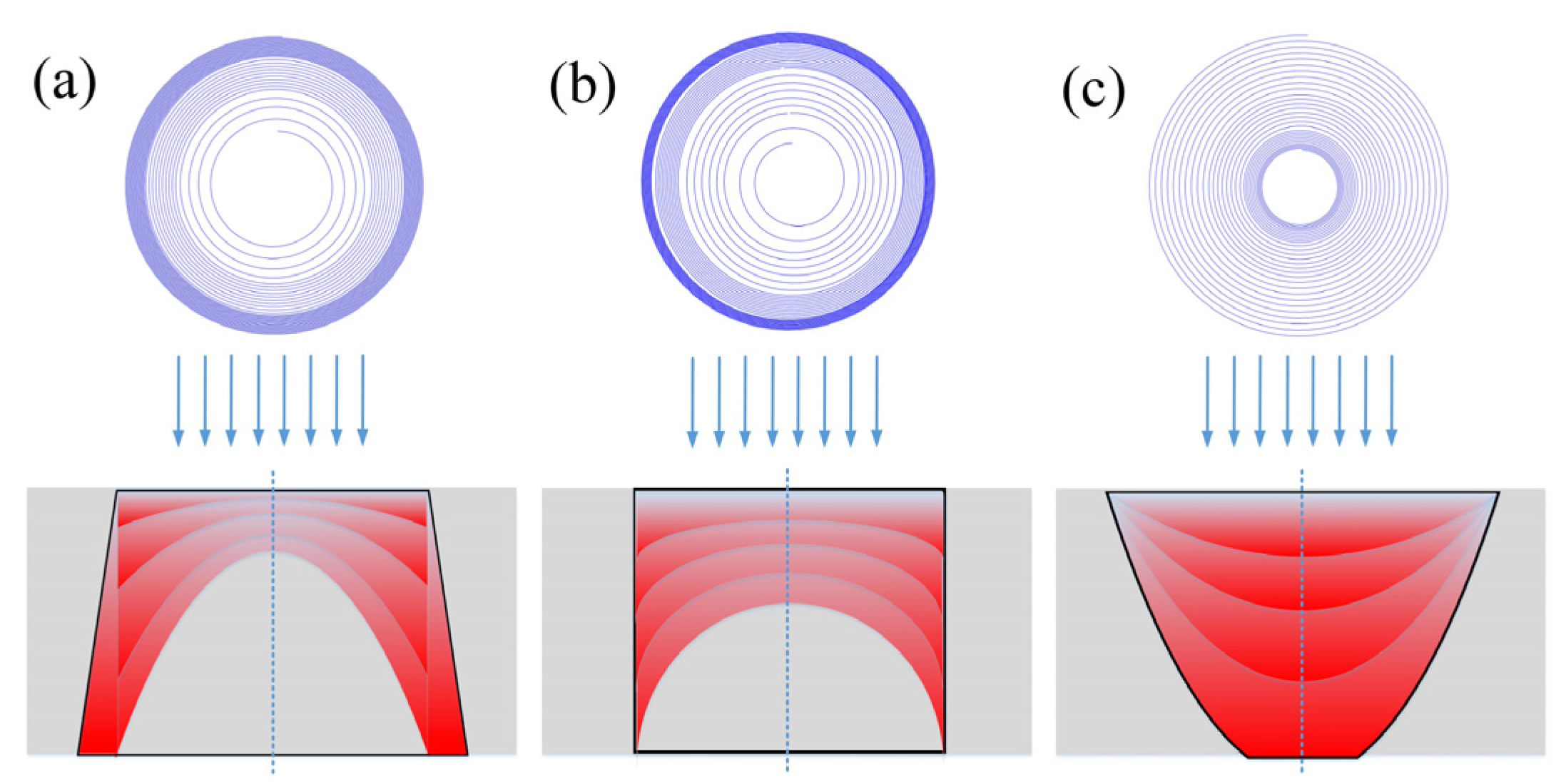
Different scanning paths of the femtosecond laser can lead to different micro-hole tapers. The formation mechanism of the inverted cone hole (Figure 8a) is described. First, by changing the scanning path, the number of cycles of the outer ring becomes relatively dense, and the energy is relatively high. This way, the depth of the microhole outer ring can be higher than that of the inner ring. Therefore, the processing contour of the microhole begins to appear from the outer ring, which is consistent with the microhole morphology in Figure 5. Moreover, due to the high energy of the outer ring, the external temperature is also accumulating as the process continues; with the increase in the depth, the taper gradually accumulates and finally forms an inverted cone. Moreover, the black oxide distribution range at the microhole entrance was smaller than that at the exit, which was due to the continuous heat accumulation. Finally, the thermal radiation at the microhole exit was larger than that at the entrance; thus, the black oxide distribution range was larger than that at the entrance, which further confirms our conjecture.
Furthermore, the formation mechanism of the straight holes (Figure 8b) is described. From Table 2, the straight cone had fewer circles in the outer diameter and more intermediate circles than the inverted cone. Therefore, the energy of the outer ring diffused less to the outer ring and finally formed a straight hole. The energy distribution in the straight pores fabrication is not uniform, because if a uniform energy distribution is used, the edge can easily diffuse energy in the microhole construction process, while the internal energy dissipation will be relatively slow. Finally, the inner ring energy is high and the outer ring energy is low. The constructed microholes are often normal cone holes. Therefore, the energy of the outer ring is slightly larger than that of the inner ring to construct a straight hole. Wang et al. [22] fabricated a film hole by spiral trepanning with average power, and a normal cone hole appeared finally. It is evident that spiral trepanning with average power cannot fabricate a straight hole.
The formation mechanism of a normal cone hole (Figure 8c) is described. Table 2 shows that the inner ring of the laser scanning path is relatively dense, and the outer ring is sparse, and the power is 55%. Therefore, the inner ring energy is higher than the outer ring energy, which is similar to the Gaussian light energy distribution. Finally, the shape of the processed microhole is also a normal cone, and the morphology is similar to that of Figure 7c. The cross section of the microhole is consistent.
In the process of microhole fabrication via femtosecond-laser processing, the factors affecting the microhole taper include the following: the initial phase, transverse displacement of the beam, the focal length of the focusing lens, beam quality, and defocusing amount. The initial phase, transverse displacement, and focal length of the focusing lens determine the laser incident angle. The beam quality is equivalent to the tool head. A good tool head will improve the processing efficiency. A poor beam quality will affect the material removal by the laser, resulting in a poor taper. The scanning path, air pressure, defocusing amount, and other factors will affect the microhole taper. This study mainly investigated the influence of the processing technology on the microhole taper. The experiments clearly showed that the different microhole taper was processed by adjusting the distribution of scanning path and power. Moreover, in addition to the influences of the scanning path and power, the influences of the pressure of air pump and defocusing amount on the microhole taper was also studied.
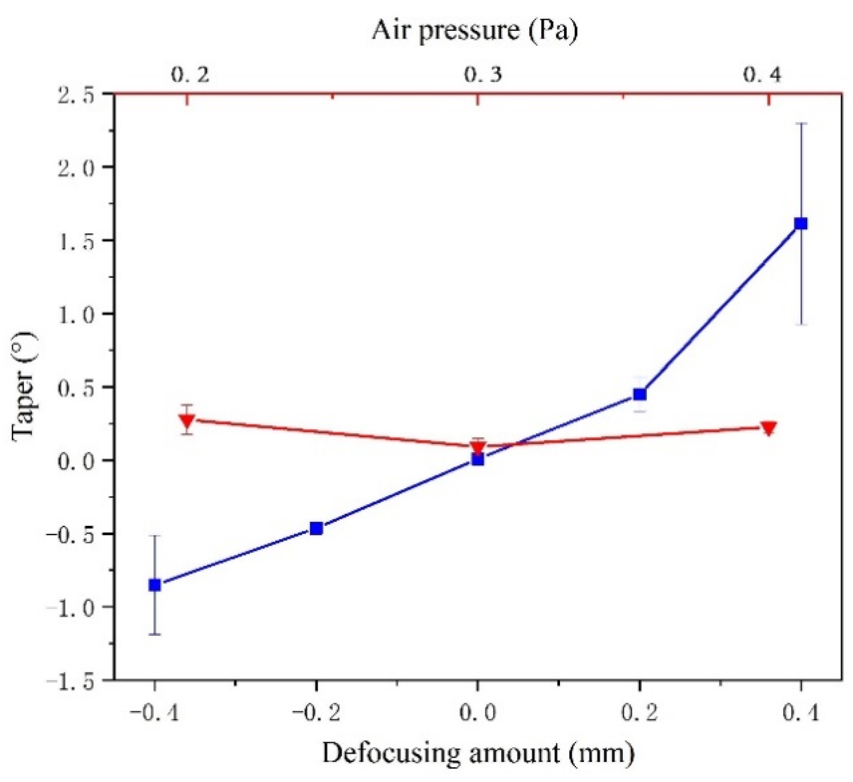
The effects of air pressure and defocusing amount on the microhole taper is shown in Figure 9. With the increase in air pressure from 0.2 Pa to 0.4 Pa, the microhole tapers were slight differences. The air pressure mainly cools down the temperature of the microhole and blows away the melt caused during the laser processing microhole. The lack of obvious slag at the entrance demonstrates this point. Besides, the air pressure has an effect on the refractive index, which affects the formation of micropores when the laser propagates through the expanding plasma and gas [26]. However, according to the previous research [27], with the air pressure continuing to increase, the heat dissipation from the molten material will increase, and thereby causing re-solidification, as a result of which obvious slag occurs at the entrance of microhole. Besides, the microhole tapers were marked variation with the change of defocusing amount. The trend of results illustrates that the negative defocus could produce the inverted cone hole, while the positive defocus could produce the normal cone hole. Moreover, the taper increased with the increase in defocusing amount. The method enlarges the taper of microholes by varying the defocusing amount, which is very important for fabricating a larger angle taper microhole. In addition, with the defocusing amount continuing to increase, the laser energy will be low and the microhole is difficult to process.
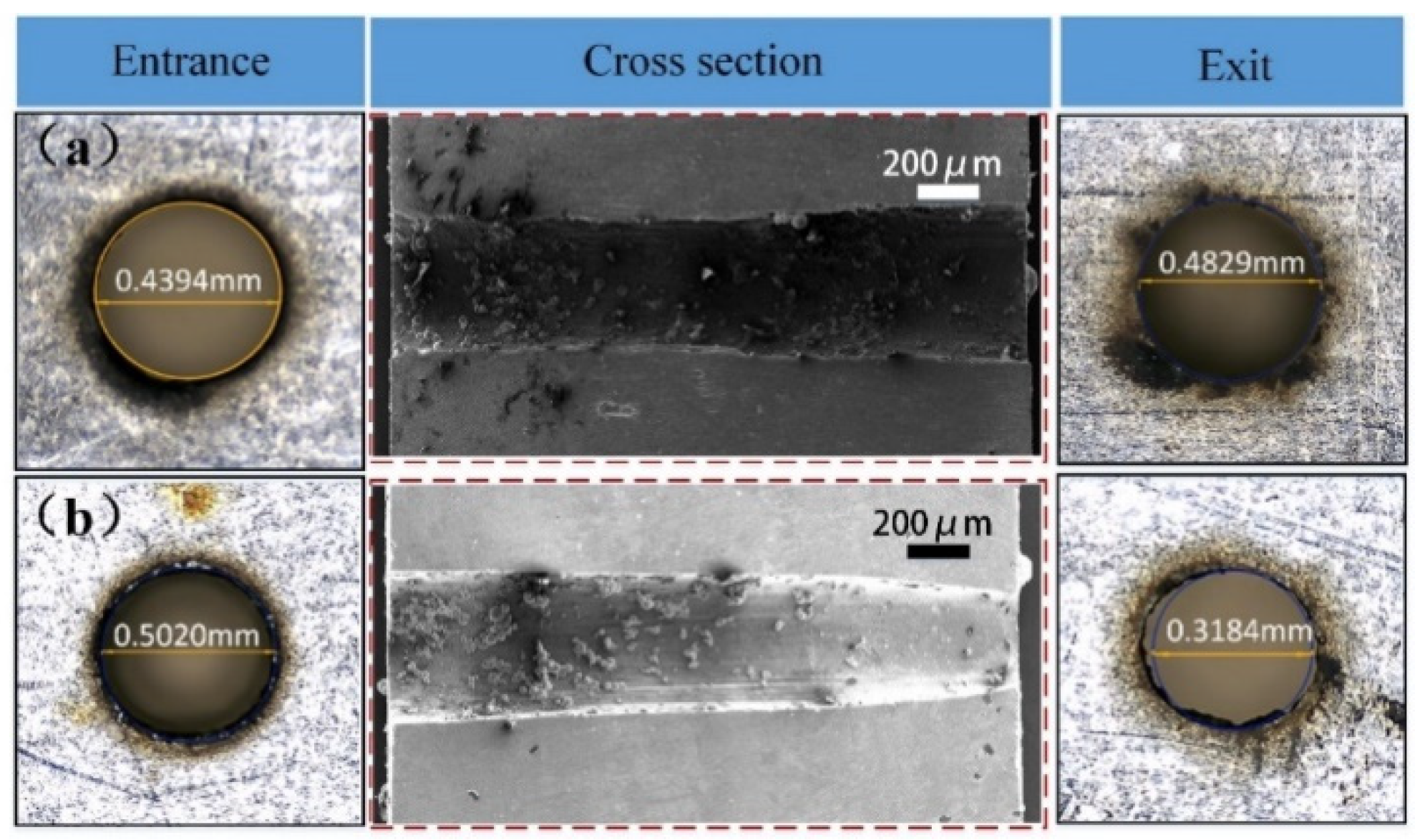
Furthermore, according to the method of varying defocusing amount, we provide some experimental results. Figure 10a shows a −1.24° taper microhole obtained with a negative defocus of 0.5 mm based on the laser processing parameters of 0.03° in Table 2. Figure 10b shows a 5.24° taper microhole obtained with a positive defocus of 0.5 mm based on the laser processing parameters of 3.09° in Table 2. The decrease in the defocusing amount will weaken the center energy of the laser spot, but the laser processing range will radiate outward. Therefore, for the case of the −1.24° taper hole, the change in the defocusing amount will cause the energy of the laser outer ring to radiate more broadly, and a microhole with an inverted cone hole can be obtained. For the 5.24° taper hole, the change in the defocusing amount will disperse the energy of the outer ring with weak energy, so it is more difficult to remove the material. However, the inner ring has higher energy, and the influence of defocusing on the inner ring is smaller than that on the outer ring. Finally, a normal cone hole with a larger taper is formed. Although the experiment results shown in Figure 10 have some impurity on the inner wall of the microhole, the method enlarges the angle of the taper microhole by increasing the defocusing amount and varying the laser processing parameters.
4. Conclusions
In this paper, the femtosecond-laser is used to perform microhole machining. By varying the scanning path and energy distribution, an inverted cone hole, straight hole, and normal cone hole could be obtained. The reasons for forming different taper microholes can primarily ascribe different energy distributions by analyzing SEM and EDX. Besides, the effects of air pressure and defocusing amount on the microhole taper were researched. The results show that air pressure has a slighter effect on the taper of the microhole. However, the increase in defocusing amount can process a large taper microhole. Compared with the traditional method and femtosecond-laser percussion drilling, ring cutting, the femtosecond-laser spiral trepanning by varying energy distribution, is very simple and highly efficient for processing different taper microholes. Moreover, owing to the ultra-short pulse cold-working characteristics of the femtosecond laser, the quality of the microhole processed was free of molten matter and cracks. However, some problems still exist —namely, that it is not easy to prepare an inverted cone with a large taper, and a small amount of molten material covers the inner wall of the micropore. Aero-turbine blade film and engine nozzles require the machining of a high-quality and different taper of a microhole; therefore, the microhole machining technology based on femtosecond-laser spiral trepanning by varying the scanning path, energy distribution and defocusing amount can be applied in aerospace, the automotive industry, and other industries.
Author Contributions
F.L. devised the research plan. G.F. performed the research and wrote the manuscript. X.Y., X.L. and G.M. provided technical help over the course of the research. C.L. helped G.F. to do the research. All authors have read and agreed to the published version of the manuscript.
Funding
This work is financially supported by the Laser Manufacturing and Additive Manufacturing Project of the National Key Research and Development Program of China (2018YFB1108000); Wenzhou Municipal Key Science and Research Program (ZG2019031).
Conflicts of Interest
The authors declare no conflict of interest.
References
- Perepezko, J.H. The Hotter the Engine, the Better. Science 2009, 326, 1068–1069. [Google Scholar] [CrossRef] [PubMed]
- Mcnally, C.A.; Folkes, J.; Pashby, I.R. Laser drilling of cooling holes in aeroengines: State of the art and future challenges. J. Mater. Sci. Technol. 2004, 20, 805–813. [Google Scholar] [CrossRef]
- Dai, P.; Yu, N.Y. Numerical Study on the Influence of Hole Shape on Film Cooling Effectiveness. Adv. Mater. Res. 2013, 716, 699–704. [Google Scholar] [CrossRef]
- Huang, W.D.; Wu, Z.J.; Gong, H.F.; Gao, Y.; Li, L.G. Effect of Nozzle Geometry on Macroscopic Behavior of Diesel Spray in the Near-Nozzle Field; SAE Technical Paper; SAE: Warrendale, PA, USA, 2013; Volume 2. [Google Scholar]
- Jia, G.; Dong, X.; Huo, Q.; Wang, K.; Mei, X. Positioning and navigation system based on machine vision intended for laser-electrochemical micro-hole processing. Int. J. Adv. Manuf. Technol. 2017, 94, 1397–1410. [Google Scholar] [CrossRef]
- Nishida, K.; Zhu, J.Y.; Leng, X.Y.; He, Z.X. Effects of micro-hole nozzle and ultra-high injection pressure on air entrainment, liquid penetration, flame lift-off and soot formation of diesel spray flame. Int. J. Engine Res. 2018, 18, 51–65. [Google Scholar] [CrossRef]
- Giridhar, M.S.; Seong, K.; Schülzgen, A.; Khulbe, P.; Peyghambarian, N.; Mansuripur, M. Femtosecond pulsed laser micromachining of glass substrates with application to microfluidic devices. Appl. Opt. 2004, 43, 4584. [Google Scholar] [CrossRef]
- Wang, Q.; Hong, W.; Dong, L. Graphene “Microdrums” on Freestanding Perforated Thin Membrane for High Sensitivity MEMS Pressure Sensor. Nanoscale 2016, 8, 7663–7671. [Google Scholar] [CrossRef]
- Wang, G.; Yu, Y.; Jiang, L.; Li, X.W.; Xie, Q.; Lu, Y.F. Cylindrical shockwave-induced compression mechanism in femtosecond laser Bessel pulse micro-drilling of PMMA. Appl. Phys. Lett. 2017, 110, 161907. [Google Scholar] [CrossRef]
- Kumar, S.; Saint Amand, F.J.; Passas, R.; Fabry, B.; Carre, B. Fractionation by micro-hole pressure screening and hydrocyclone applied to deinking line rationalization and future manufacturing concept. TAPPI J. 2015, 14, 268–280. [Google Scholar] [CrossRef]
- Chang, C.S.; Hourng, L.W. Two-dimensional two-phase numerical model for tool design in electrochemical machining. J. Appl. Electrochem. 2001, 31, 145–154. [Google Scholar] [CrossRef]
- Haisch, T.; Mittemeijer, E.J.; Schultze, J.W. Electrochemical machining of the steel 100Cr6 in aqueous NaCl and NaNO3 solutions: Microstructure of surface films formed by carbides. Electrochim. Acta 2001, 47, 235–241. [Google Scholar] [CrossRef]
- Srivastava, V.; Pandey, P.M. Effect of process parameters on the performance of EDM process with ultrasonic assisted cryogenically cooled electrode. J. Manuf. Process. 2012, 14, 393–402. [Google Scholar] [CrossRef]
- Liao, Y.S.; Huang, J.T.; Su, H.C. A study on the machining-parameters optimization of wire electrical discharge machining. J. Mater. Process. Technol. 1997, 71, 487–493. [Google Scholar] [CrossRef]
- Tehuacanero-Cuapa, S.; Reyes-Gasga, J.; Bres, E.F.; Palomino-Merino, R.; Garcia-Garica, R. Holes drilling in gold and silver decahedral nanoparticles by the convergent beam electron diffraction electron beam. Radiat. Eff. Defects Solids 2014, 169, 838–844. [Google Scholar] [CrossRef]
- Zhou, H.; Zhang, J.; Yu, D.; Feng, P.F.; Cai, W.C. Advances in rotary ultrasonic machining system for hard and brittle materials. Adv. Mech. Eng. 2019, 11, 168781401989592. [Google Scholar] [CrossRef]
- Jamaludin, F.S.; Mohd Sabri, M.F.; Said, S.M. Controlling parameters of focused ion beam (FIB) on high aspect ratio micro holes milling. Microsyst. Technol. 2013, 19, 1873–1888. [Google Scholar] [CrossRef]
- Jia, H.N.; Yang, X.J.; Zhao, W.; Zhao, H.L.; Du, X.; Yang, Y. Femtosecond Laser Pulses for Drilling the Shaped Micro-Hole of Turbine Blades. Chin. Phys. Lett. 2013, 30, 4. [Google Scholar] [CrossRef]
- Yang, X.J.; Li, M.; Wang, L.; Zhou, H.L.; Chen, G.H. A New Method of Processing High-Precision Micro-Hole with the Femtosecond Laser. Appl. Mech. Mater. 2013, 268–270, 382–386. [Google Scholar] [CrossRef]
- Ancona, A.; Dring, S.; Jauregui, C.; Rser, F.; Limpert, L.; Nolt, S.; Tunnermann, A. Femtosecond and picosecond laser drilling of metals at high repetition rates and average powers. Opt. Lett. 2009, 34, 3304–3306. [Google Scholar] [CrossRef]
- Huang, H.; Yang, L.M.; Liu, J. Micro-hole drilling and cutting using femtosecond fiber laser. Opt. Eng. 2014, 53, 051513. [Google Scholar] [CrossRef]
- Wang, M.; Yang, L.; Zhang, S.; Wang, Y. Experimental investigation on the spiral trepanning of K24 superalloy with femtosecond laser. Opt. Laser Technol. 2018, 101, 284–290. [Google Scholar] [CrossRef]
- Park, J.K.; Yoon, J.W.; Kang, M.C.; Cho, S.H. Surface effects of hybrid vibration-assisted femtosecond laser system for micro-hole drilling of copper substrate. Trans. Nonferrous Met. Soc. China 2012, 22, s801–s807. [Google Scholar] [CrossRef]
- Shi, C.H.; Ren, N.H.; Wang, H.X.; Xia, K.B.; Wang, L. Effects of ultrasonic assistance on microhole drilling based on Nd:YAG laser trepanning. Opt. Laser Technol. 2018, 106, 451–460. [Google Scholar] [CrossRef]
- Khai, X.P.; Rie, T.; Yoshiro, I. Trepanning drilling of microholes on cemented tungsten carbide using femtosecond laser pulses. J. Laser Appl. 2012, 24, 1095–1101. [Google Scholar]
- Zhao, W.Q.; Shen, X.W.; Liu, H.D.; Wang, L.Z.; Jiang, H.T. Effect of high repetition rate on dimension and morphology of micro-hole drilled in metals by picosecond ultra-short pulse laser. Opt. Laser. Eng. 2020, 124, 105811.1–105811.8. [Google Scholar] [CrossRef]
- Xia, B.; Jiang, L.; Li, X.W.; Yan, X.L.; Zhao, W.W.; Lu, Y.F. High aspect ratio, high-quality microholes in pmma: A comparison between femtosecond laser drilling in air and in vacuum. Appl. Phys. A 2015, 119, 61–68. [Google Scholar] [CrossRef]
Figure 1.
Different laser processing methods.

Figure 2.
Experimental setup of femtosecond-laser processing.

Figure 3.
Scanning path of the microhole in femtosecond-laser processing.

Figure 4.
Inverted cone hole processed by femtosecond: (a) microhole entrance; (b) microhole exit.

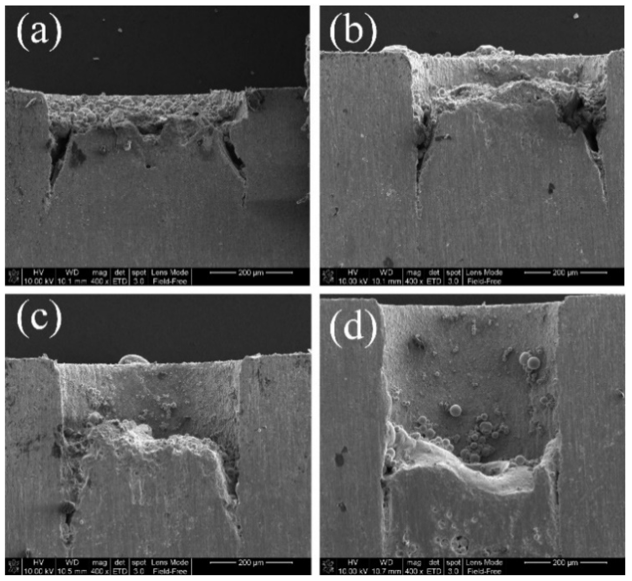
Figure 5.
Tapers of the inverted cone under different feeding layers: (a) 2, (b) 4, (c) 10, and (d) 50.
Figure 5.
Tapers of the inverted cone under different feeding layers: (a) 2, (b) 4, (c) 10, and (d) 50.

Figure 6.
Morphology of microholes with a taper angle of 0.03°: (a) microhole entrance; (b) microhole exit; (c) microhole cross section.
Figure 6.
Morphology of microholes with a taper angle of 0.03°: (a) microhole entrance; (b) microhole exit; (c) microhole cross section.

Figure 7.
Morphology of microholes with a taper angle of 3.09°: (a) microhole entrance; (b) microhole exit; (c) microhole cross section.
Figure 7.
Morphology of microholes with a taper angle of 3.09°: (a) microhole entrance; (b) microhole exit; (c) microhole cross section.

Figure 8.
Microhole process with different tapers due to different scanning paths: (a) inverted cone; (b) straight cone; (c) normal cone.
Figure 8.
Microhole process with different tapers due to different scanning paths: (a) inverted cone; (b) straight cone; (c) normal cone.

Figure 9.
Effects of air pressure and defocusing amount on the microhole taper.

Figure 10.
Effect of defocusing on the microhole taper: (a) −1.24° taper; (b) 5.24° taper.


Table 1.
Mass ratios of different elements in different regions of the microhole entrance and exit.
| Element | A | B | C | D |
|---|---|---|---|---|
| C | 0.88 | 0.82 | 1.32 | 1.08 |
| O | 6.35 | 5.17 | 6.32 | 5.07 |
| Si | 0.92 | 0.94 | 1.37 | 1.14 |
| Cr | 16.03 | 16.19 | 16.90 | 16.98 |
| Fe | 68.13 | 68.87 | 66.30 | 68.32 |
| Ni | 7.69 | 7.90 | 7.80 | 7.41 |
Table 2.
Scanning parameters of femtosecond-laser with different tapers.
| Taper | 0.03° | 3.09° | ||||
|---|---|---|---|---|---|---|
| Scanning Parameters | Radius Angle Increment | Number of Turns | Power (%) | Radius Angle Increment | Number of Turns | Power (%) |
| Lap 1 | 2 | 2 | 50 | 0.2 | 4 | 55 |
| Lap 2 | 1 | 6 | 55 | 0.3 | 6 | 55 |
| Lap 3 | 0.3 | 11 | 60 | 0.6 | 8 | 55 |
| Lap 4 | 0.1 | 14 | 65 | 0.8 | 10 | 55 |
Table 3.
Mass ratios of different elements at the top, center and bottom of the microhole cross section.
Table 3.
Mass ratios of different elements at the top, center and bottom of the microhole cross section.
| Element | Top | Centre | Bottom |
|---|---|---|---|
| C | 1.42 | 1.01 | 0.73 |
| O | 19.99 | 20.47 | 15.85 |
| Si | 1.48 | 1.97 | 1.32 |
| Cr | 15.09 | 15.24 | 15.79 |
| Fe | 56.41 | 55.04 | 59.72 |
| Ni | 5.61 | 6.26 | 6.59 |
Table 4.
Mass ratios of different elements at the top, center, and bottom of the microhole cross section.
Table 4.
Mass ratios of different elements at the top, center, and bottom of the microhole cross section.
| Element | Top | Center | Bottom |
|---|---|---|---|
| C | 1.71 | 0.99 | 0.97 |
| O | 9.55 | 7.04 | 5.86 |
| Si | 1.49 | 1.10 | 1.05 |
| Cr | 14.04 | 15.84 | 17.10 |
| Fe | 68.26 | 70.49 | 70.19 |
| Ni | 4.95 | 4.54 | 4.83 |
Publisher’s Note: MDPI stays neutral with regard to jurisdictional claims in published maps and institutional affiliations. |
© 2020 by the authors. Licensee MDPI, Basel, Switzerland. This article is an open access article distributed under the terms and conditions of the Creative Commons Attribution (CC BY) license (http://creativecommons.org/licenses/by/4.0/).
Share and Cite
MDPI and ACS Style
Li, F.; Feng, G.; Yang, X.; Li, X.; Ma, G.; Lu, C. Research on Microhole Processing Technology Based on the Femtosecond-Laser Spiral Trepanning Method. Appl. Sci. 2020, 10, 7508. https://doi.org/10.3390/app10217508
AMA Style
Li F, Feng G, Yang X, Li X, Ma G, Lu C. Research on Microhole Processing Technology Based on the Femtosecond-Laser Spiral Trepanning Method. Applied Sciences. 2020; 10(21):7508. https://doi.org/10.3390/app10217508
Chicago/Turabian StyleLi, Fengping, Guang Feng, Xiaojun Yang, Xiaogang Li, Guang Ma, and Chengji Lu. 2020. "Research on Microhole Processing Technology Based on the Femtosecond-Laser Spiral Trepanning Method" Applied Sciences 10, no. 21: 7508. https://doi.org/10.3390/app10217508
Note that from the first issue of 2016, this journal uses article numbers instead of page numbers. See further details here.