1. Introduction
Dating back to the first studies conducted by Professor Brånemark, the process of dental implant screw osseointegration has been recognized as an interfacial process that is controlled by the events that occur at the interface between the host tissue and the implant surface [
1]. In the bone surrounding dental implants, cell behavior is determined by the treated surface of the implant [
1,
2,
3].
As a consequence, scientific research has devoted a lot of effort to the study of the superficial chemical and physical properties of implant screws and their effects on the osseointegration process [
4,
5,
6,
7,
8,
9].
Surface features considered most important are:
- -
the chemical composition of the surface. Dental implants are mostly made of titanium which is an extremely biocompatible material thanks to its passivation. The surface, however, is unique in that it has a chemical composition that is not only dictated by the material it is made of, but also by peculiarly being a boundary layer (contact with the external atmosphere and the related effects), as well as all the processes that the device undergoes in its realization: turning, surface treatment, cleaning, packaging [
10]. As a consequence, the surface chemical composition of implant screws is a separate variable and must always be independently verified;
- -
the topography of the surface: while the surface of the first generation implant screws was substantially only turned (machined), the current surfaces are roughened in a controlled way by means of processes that stimulate peri-implant bone regeneration through the effect of the roughness on the biological behavior of peri-implant tissues (affecting blood and its components, inflammatory cells, osteogenic cells). The surface treatments of dental implant screws have undergone an evolutionary process over the years, which has led to well-defined and widely studied topographies whose characteristics are usually defined quantitatively by roughness parameters.
The study of the properties listed above is of great importance for understanding the characteristics of a dental implant and for assessing the accuracy and awareness adopted in the production process given the extensive and varied options available today.
Moreover, not only an increasing number of surface modifications are constantly introduced but also different treatments are often applied in the different areas of the implant body in order to improve osseointegration in the apical portion while reducing the risk for plaque accumulation in the coronal part and favoring soft tissue integration [
11,
12,
13,
14].
In addition, recently, implants made of other materials, including zirconia, have been developed, the surfaces of which need to be further investigated [
15,
16].
The choice of the implant device to be inserted in a specific clinical case cannot prescind from the knowledge of the implant characteristics that might affect the clinical outcome.
For these reasons, the surface characteristics of 5 different commercially available dental implants were studied in this investigation.
This work was intended to measure surface properties deemed important for the intended clinical purpose of 5 different types of dental implants. In particular, the assessments took into consideration the chemical composition of the implant surface and the topography of the surface quantified by the roughness values.
2. Materials and Methods
Ethics approval was not required for this in vitro study.
2.1. Dental Implants Investigated
Five different screw-shaped dental implants were investigated (
Table 1). For each implant type, three identical implants were used: one sample was used for topography evaluation (SEM-EDX analysis, roughness), one sample for XPS analysis, and the remaining sample was kept in reserve should anomalous results emerge with the need for confirmation. All samples were sent to the analysis laboratory (Nobil Bio Ricerche Srl, Portacomaro, AT, Italy) in their original sealed and perfectly intact package. Each specimen, therefore, was in the condition as used clinically. For each type of analysis, the samples were extracted from their packaging immediately before the analysis, taking every effort to prevent any contamination or external influences.
According to the manufacturers’ indications, of the four titanium implants investigated, the two by Sweden&Martina (Syra and Prama) present the proprietary ZirTi surface (zirconium sand-blasted acid-etched titanium), with the Prama implant characterized by a collar machined with the UTM (ultrathin threaded microsurface) technique.
Biomet 3i realizes the T3 implant whose collar has the same DAE (dual acid-etched) surface of the well-known Osseotite® implant. The rest of the body of T3 is also sand-blasted before being acid-etched and then undergoes deposition of calcium phosphate nanocrystals following the DCD (discrete crystalline deposition) procedure.
The Shard Implant by Mech&Human presents a double acid-etched surface.
The NobelPearl zirconia implant by Nobel Biocare has the sandblasted and acid etched ZerafilTM surface.
2.2. Evaluation of Topography and Surface Roughness
Topography and surface roughness of the implants being studied were assessed by scanning electron microscopy (SEM) in normal mode and with a diffuse retro electron detector (BSE = back scattered electrons). The observations were made using an EVO MA 10 instrument (ZEISS). The main parameters of the analysis (electron high tension = EHT, working distance = WD, magnification = Mag, type of detector = Signal A) are shown directly in the photographs. SEM analysis carried out using a detector capable of detecting backscattered electrons (BSE) provides indications on the presence of heterogeneous elements with respect to those that make up the sample under examination due to the fact that backscattering efficiency is a function of the atomic number and any contaminants of different chemical nature are easily visualized thanks to the different shades of gray that they produce. The application of this method of observation is therefore of considerable use in evaluating the effectiveness of material cleaning protocols. In light of this, low-magnification images have been taken for each sample, along with the detector for backscattered electrons, in order to have an overview and the qualitative chemical information of the implant surfaces. The images taken with this mode have Signal A = CZ BSD written on the white stripe at the bottom, while those done with the normal detector have Signal A = SE1 written in the same location.
Due to its non-metallic nature, NobelPearl tapered implant was subjected to metallization with 99.99 gold (Agar Sputter Coater, AGAR SCIENTIFIC LTD) in order to create electron conductivity and, therefore, allowed for the use of this analytical technique. For the other implants analyzed, no preparation was necessary.
Before each SEM observation, an EDX (energy dispersive X-ray analysis) spectrum of the implant under examination was obtained to confirm the chemical nature of the material used for its construction. For this analysis, an Atzec EDX microprobe, produced by Oxford, was used.
Surface roughness was quantitatively assessed using the stereo-SEM method (SSEM) with dedicated software to convert traditional SEM images into three-dimensional data (Mex 6.1, Alicona Imaging). In particular, using the principles of stereoscopic vision, a representative image of the topography was obtained from two slightly different viewing angles, that is, with the specimen holder in a horizontal position and with a slight inclination (tilt angle). The software combined the two images and collected three-dimensional information, allowing the user to extract the various roughness parameters defined in the literature. In particular, according to the procedure adopted, a tilt angle of 5 degrees was used, images were obtained at 2000×, and the analyzed area was 90 × 120 µm, the geometric area evaluated was therefore 90 × 120 = 10,800 µm2.
The following area roughness parameters were calculated, according to ISO25178 parameters:
Sa: average height deviation of the selected area; it expresses, as an absolute value, the difference in height of each point compared to the arithmetical mean of the surface;
Sz: maximum height of the selected area; it is defined as the sum of the greatest peak height value and the greatest pit depth value within the defined area.
Sdr: relationship between developed area and geometric area, is expressed as the percentage of the definition area’s additional surface area contributed by the texture as compared to the planar definition area. The Sdr of a completely level surface is 0.
Sa, Sz, and Sdr are the equivalent of the roughness parameters Ra, Rz, and Rdr when recorded on a 3-dimensional surface. They are modern parameters derived from processing of data within an area and not along a line.
Ra/Sa and Rz/Sz values, that are the most common parameters seen in different publications, are purely height-descriptive parameters providing vertical roughness information, that is, they are related to how high the roughness present on the surface is. Sdr, on the other hand, is a horizontal parameter, as it basically represents how much the surface area of the implant is increased following the treatment.
2.3. Evaluation of the Surface Chemical Composition
Implant surface chemical composition was measured by XPS (X-ray photoelectron spectroscopy) also named ESCA (electron spectroscopy for chemical analysis). Both names, which indicate the same technique, are used in the scientific literature in this regard [
10].
This technique obtains the qualitative and quantitative composition of the outermost layers of materials (in the case of metals, the depth analyzed is approximately 5 nm) and therefore provides a direct indication of the chemical composition of the layers of material that come into effective contact with the bone tissue.
The XPS analysis was performed with a Perkin Elmer PHI 5600 ESCA System instrument. It is equipped with a monochromatic X-ray source with Al anode, maintained at 20 kV with a power of 200 W. The analyzed depth is about 5 nm with an area of about 300 µm in diameter. The pressure inside the analysis chamber was maintained at around 10−9 Torr. For the only NobelPearl zirconia implant, made with a non-conductive material and therefore more susceptible to charging phenomena, the XPS spectrum was acquired with the same instrument but with a non-monochromatic source with Mg anode.
For all the samples, the analysis result is expressed in atomic%. The sterile packages containing the implants to be analyzed were opened immediately before the start of the analysis and the samples were subjected to analysis without the need for preparation, reducing, in fact, the manipulations to a minimum and avoiding any contact with the surface. The analysis was carried out on different areas of the surface, to highlight, if necessary, the contributions of the various surface modification processes adopted.
3. Results
The presentation of the results obtained is shown in the following sections for each dental implant. The first part concerns SEM evaluation, the second part reports the analysis of the surface chemical composition.
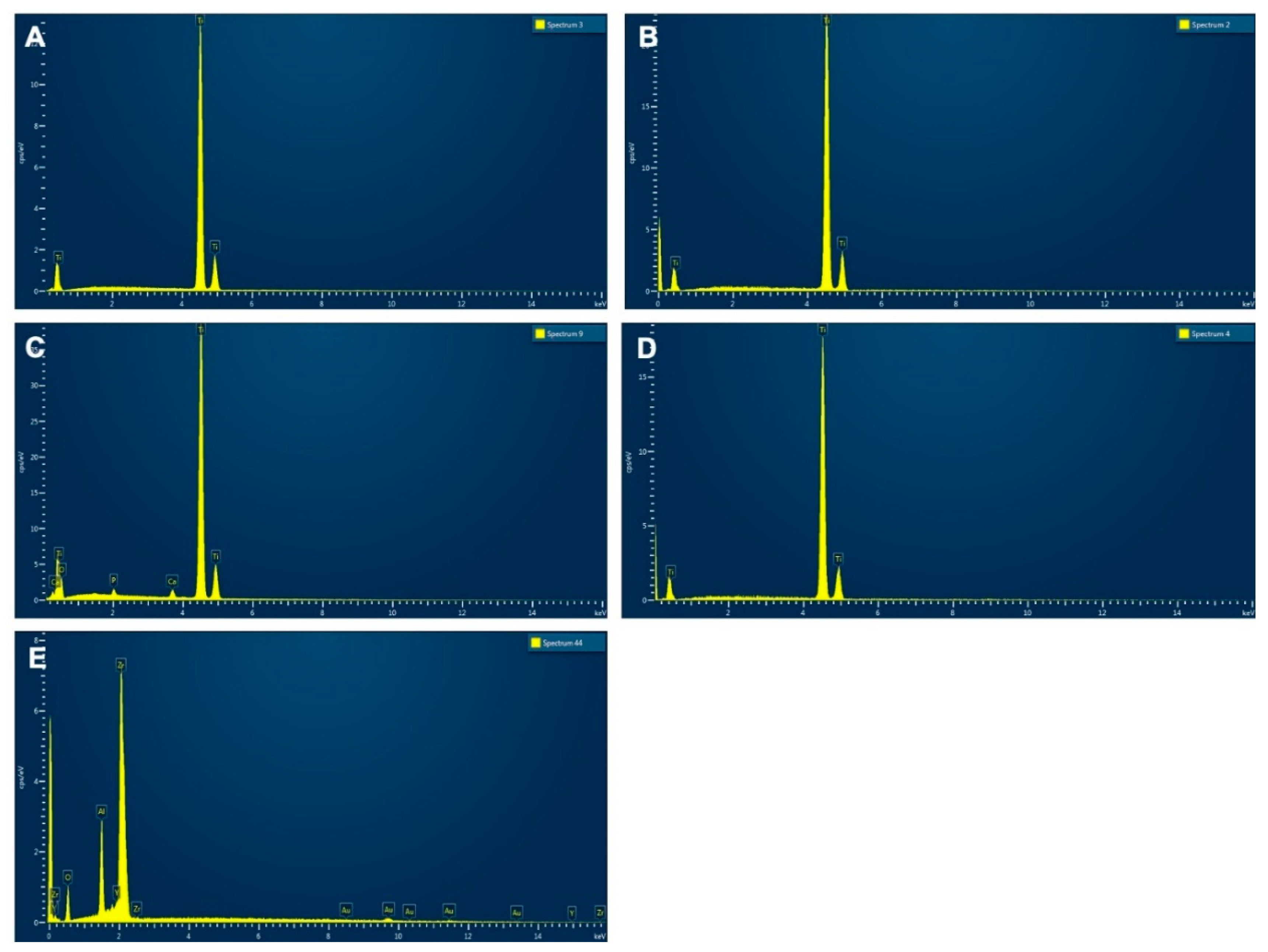
3.1. Syra
The EDX spectrum of the Syra system is shown in
Figure 1A. The spectrum highlights the only titanium signal and confirms that the implant is made of cp titanium (commercially pure titanium), very likely grade 4 titanium.
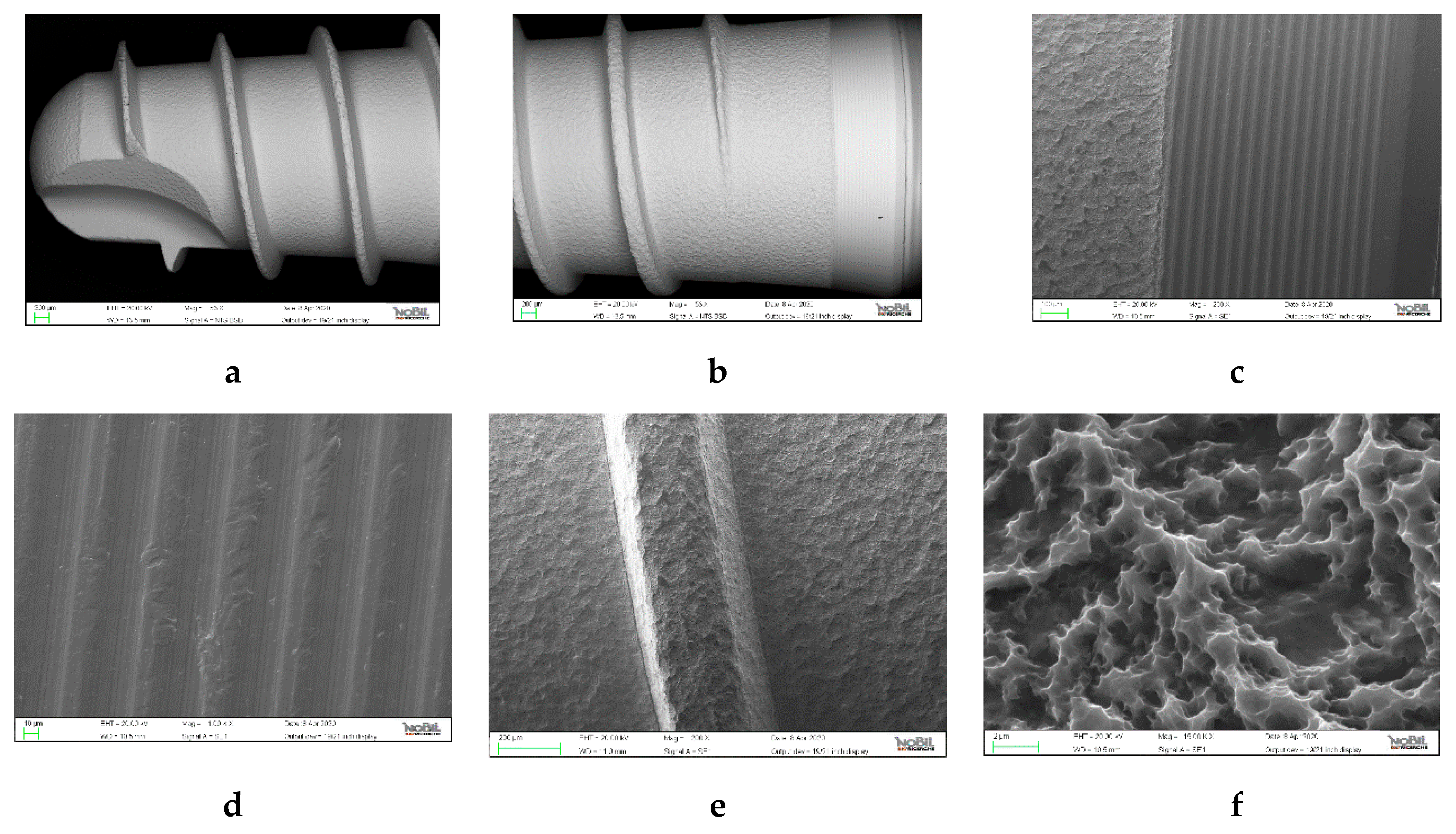
The observations made by SEM analysis are documented in
Figure 2.
Low magnification images in backscattered mode (
Figure 2a) show that the presence of black points or areas with different shades of gray is very limited, mostly centered on the high portions of the threads, where some contact is inevitable. From this type of observation, the implant surface appears very clean and the mechanical processing is of good quality.
Images obtained by conventional methods (secondary electrons) show the area of passage between the roughened part of the body and collar of the Syra implant (
Figure 2b) and exhibit parallel lines that run along the horizontal axis of the implant (
Figure 2c), typically due to the mark left by the tool in the machining process.
Regarding the topography of the surface, at low magnifications (
Figure 2e), a structure with large basins (about 10 µm) is observed, which is typically due to the plastic deformation induced by the impact of a sandblasting agent. The sandblasting effect is evenly distributed over the surface and is not too marked, that is, the basins do not have large depths. The shape of the impact basins is slightly different from that traditionally observed in classic sandblasting with corundum (alumina). In fact, the manufacturer notes a sandblasting process performed with zirconium oxide (ZirTi surfaces). It is not clear whether the contained roughness induced by this sandblasting process is due to the material or the processing conditions related to the use of a rather modest pressure. Increasing the magnifications (
Figure 2f), a micro-structure is visible, with distance between peaks of the order of the µm or less, homogeneously diffused on the surface. This micro-structure is typical of double acid attack processes. Basically, the images suggest that the roughened part of the implant had been subjected to a sandblasting process, followed by a double acid attack, based on procedures initially developed by Straumann’s SLA (sandblasted large grit, acid etched), although the sandblasting in this case is more moderate and performed with a different sandblasting agent.
To report the topography observed quantitatively, surface roughness data were acquired, as previously described. False color images (
Figure 3) were obtained from the stereoscopic processing of SEM images, where each color corresponds to the height scale shown in the image. In the image reporting the central part of the body of Syra, the dark red areas are located 3 µm below the central plane, the orange ones about 6 µm above, the difference in height between them is therefore about 9 µm.
The quantification of data using the area roughness parameters defined by ISO25178 provides the results reported in
Table 2.
By comparing the data, a very important aspect, which will be taken up again later, was observed: in the collar area, due to the intrinsic roughness created by the machining lines described above, there are vertical asperities comparable with those induced by the roughening process, as evident in the images. Therefore, the height parameters Sa and Sz did not provide significant differences between the two zones, despite the different roughening processes adopted. Sdr, however, picks up the topographic difference between the two areas very well and indicates that, due to the erosion of the surface induced by acid etching, the contact area in the treated area is much greater than that of the collar.
3.2. Prama
The EDX spectrum of the Prama system is shown in
Figure 1b.
Even in this case, the dominant signal of titanium is observed, meaning it is titanium cp (commercially pure titanium) and very likely grade 4 titanium.
Figure 4a–c was obtained in backscattered mode and the comments are similar to the previous ones reported for the Syra implant: the surface is very clean and free from significant contamination. For
Figure 4d–f, obtained in conventional mode, all the considerations just explained apply both for the collar and for the roughened area which has plastic deformation from visible sandblasting observed at low magnifications, while micro-structure deformation due to double attack with acid can also be easily observed at greater magnifications. Even in this case, such as for Syra, sandblasting using zirconium oxide took place according to the same ZirTi process.
Note that in this case the collar had a gold color which was obtained by an anodizing process. This coloring, which does not involve the addition of pigments or additives, is obtained by means of an electrochemical process which promotes the growth of the surface titanium oxide layer, transparent per se, up to a thickness of the order of 50–200 nm, and is the cause of the formation of interference colors. The thickness of the oxide surface layer is controlled by the potential difference applied in the electrochemical process. In this case, a voltage suitable for the formation of gold coloring was applied as a result of an oxide surface layer of about 100–120 nm thick. As visible in the images of the collar, the process did not involve significant alterations to the surface topography which remained substantially similar to that of a machined implant.
Additionally, in this case, the color-scale elaborations of different areas of the surface are provided (
Figure 3).
Table 2 shows the roughness values obtained.
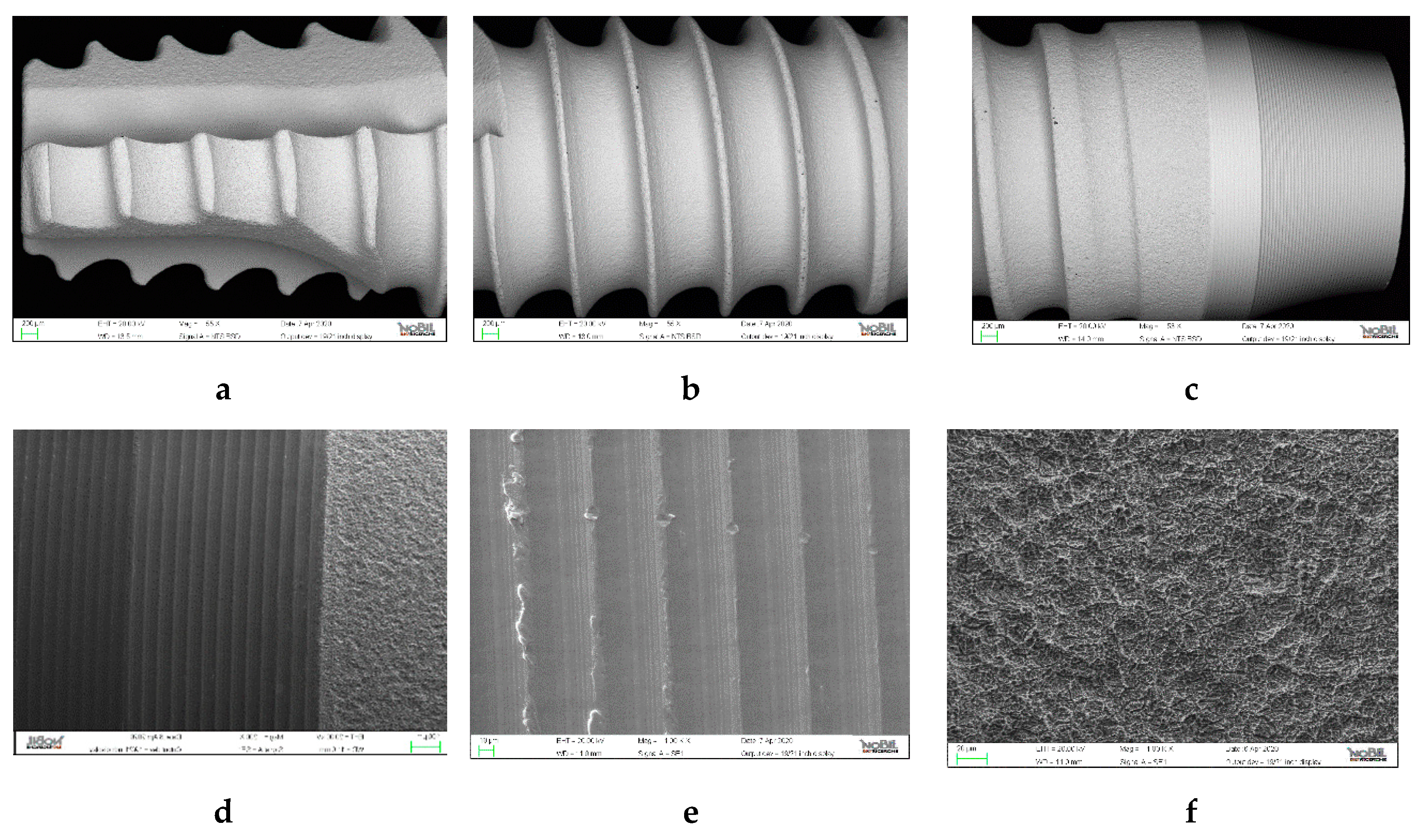
3.3. 3i T3
The EDX spectrum of the 3i T3 implant is shown in
Figure 1c.
In this case, in addition to the dominating presence of Ti, a weak but significant signal of calcium and phosphorus is observed. In fact, as indicated by the manufacturer, this product bases its interaction with the host tissue on three different characteristics: two topographical and one chemical. The topographical ones will be described shortly, with SEM images (
Figure 5). As regarding the chemical characteristic, the presence of calcium phosphate nanocrystals (diameter claimed 0.01–0.1 µm) deposited on the surface by sol-gel technique is a process commercially known as DCD (discrete crystal deposition). The EDX spectrum therefore confirms the presence of calcium phosphate, a topic that will be taken up in the section on surface analysis using XPS.
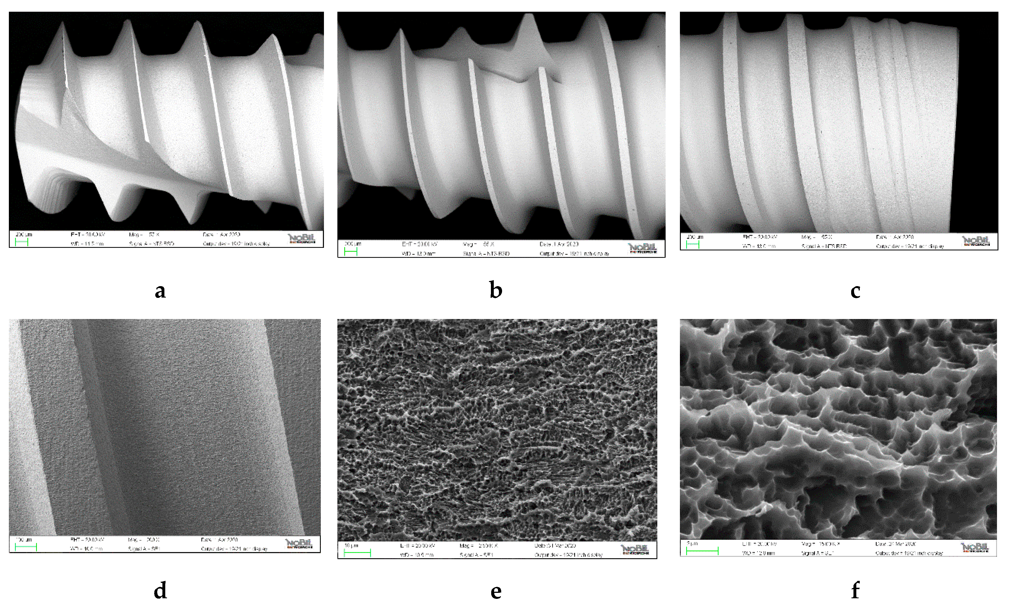
Moving on to SEM observations, in the low magnification backscattered images, the surface appears generally clean, although a greater number of black areas or accumulations can be observed compared to the previous implants, particularly in the collar area.
Figure 5b also highlights the different topographical areas of the surface: the threaded area shows signs of sandblasting much more marked than what was observed in the previous cases. The passage area between the rougher body and the collar is visible in
Figure 5c. In fact, the two topographical features mentioned are the following: the coronal area is roughened by double acid etching (DAE), the proprietary process that 3i introduced with the Osseotite surface. It produces the only micro-structure, already commented on for previous implants (
Figure 5d). The threaded area (
Figure 5e) is instead subjected to sandblasting followed by double acid etching, as in the previous cases, but, evidently, with a much more aggressive sandblasting (larger grain sizes, greater pressure). The aim is to provide a double roughness, more contained in the coronal area to reduce the negative effects of any bacterial colonization, and more significantly in the coronal area to maximize the pro-osteogenetic effects induced by the roughness. Both topographical areas also present calcium phosphate nanocrystals, which can be seen in the images at higher magnifications (
Figure 5f).
The different roughnesses are very well reflected in the three-dimensional processing (
Figure 3) and in the roughness data obtained and shown in
Table 2.
The remarkable effect is evident, and can also be appreciated vertically, induced by heavy sandblasting which created very large craters. The double acid etching does not affect the vertical values as much as the contact area.
3.4. Shard Implant
The EDX spectrum of the Shard Implant is shown in
Figure 1d.
The dominant signal of titanium is observed, indicating that also this implant is made of cpTi (commercially pure titanium), very likely grade 4 titanium.
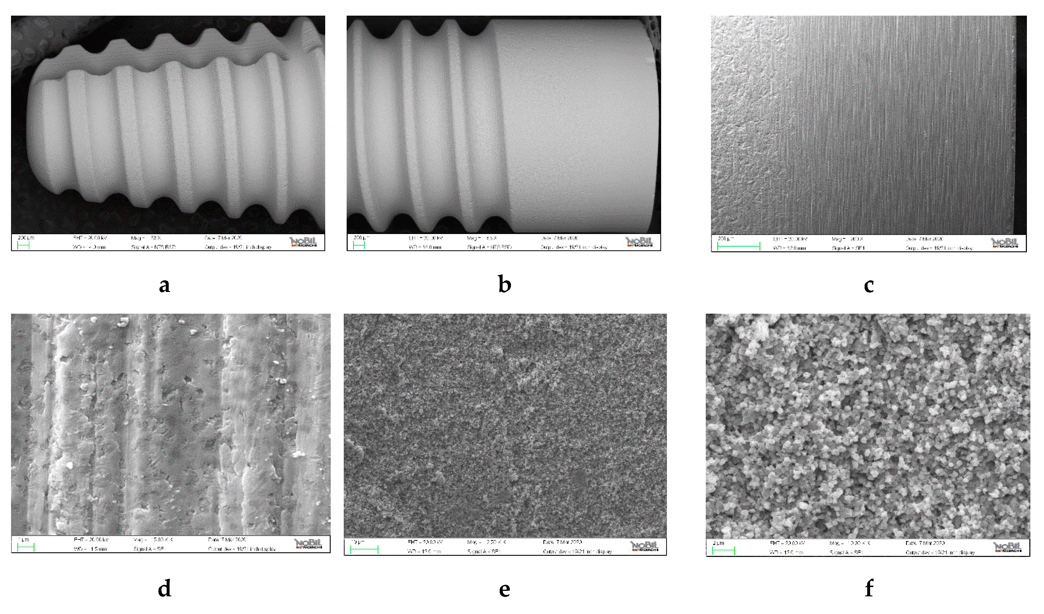
Figure 6a–c, in backscattered mode, also indicates in this case a very clean surface and an excellent degree of mechanical processing. Note that, unlike Syra and Prama and in analogy to 3i T3, the entire surface is treated and there is no machined portion at the collar.
Figure 6d–f offers greater magnifications of the surface topography. This case also demonstrates a micro-structure obtained by double acid etching and the typical “sponge” structure is very clearly visible in the images at a higher magnification, with peaks separated by distances of the order of a micrometer or less. This feature, a major innovation in micro-structured surfaces since the aforementioned Osseotite, allows for an effective activation of clotting and is the basis of the success and diffusion of this process.
The color-scale processing is provided in
Figure 3 and the roughness data are shown in
Table 2. Additionally, in this case, the salient figure is the significant increase in the surface area.
3.5. Nobel Pearl
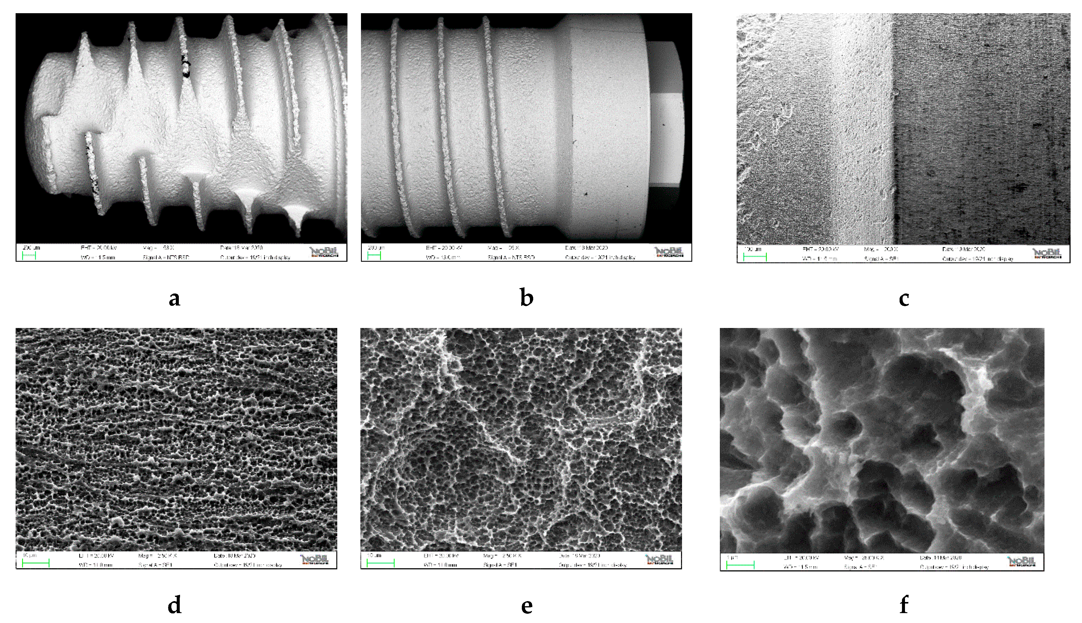
The EDX spectrum of the NobelPearl implant is shown in
Figure 1e.
It is a completely different material with respect to the previous ones as the implant is actually ceramic, made of zirconia (zirconium oxide), with a structure technologically reinforced with yttrium and aluminum oxides. The gold signals in the EDX spectrum derive from the metallization process that the implant was subjected to before the SEM observation.
As for the results of SEM observations, the images in backscattered mode reveal a very clean surface also in this case (
Figure 7a,b).
Figure 7c shows, in conventional mode, the passage between the collar and the threaded and roughened portion. The effects of minimal acid infiltration are visible in the collar that is protected during the roughening treatment. In fact, the treatment processes of zirconia implants are much longer than those of conventional implants and a minimum of diffusion between the two areas is possible.
Figure 7e,f, on the other hand, refers to the roughened portion and shows some details of the topography, markedly very different from that of the collar area. Additionally, in this case, a micro-structure is observed following the roughening process, and the appearance, very clearly visible in
Figure 7f, is typical of acid etching treatments.
Roughness quantification provided the data reported in
Table 2. Additionally, in this case, the increase in surface area represented by Sdr is the data that best captures the topographical variation between the two areas (collar vs. implant body).
3.6. Evaluation of the Surface Chemical Composition
With regard to the samples in question, the XPS analysis provided the spectra as images.
Table 3 reports the surface chemical composition obtained from the spectra themselves.
The data obtained can be commented as follows:
- -
With regards to classic systems (Syra, Prama, and Shard), the measured composition is very satisfactory and confirms the SEM-backscattered data which suggests a significant degree of surface cleaning.
- -
The anodized collar of Prama has a high phosphorus value: this is expected as the anodizing process often takes place in solutions that contain phosphates, it known that phosphorus is incorporated in the oxide layer formed following the anodizing process.
- -
The surface composition of 3i T3 confirms and explores what had already emerged from the EDX analysis and what was claimed by the manufacturer. In addition to the topographical modification, this implant surface also has a chemical modification, highlighted by the high signal of calcium and phosphorus due to the nanocrystals deposited by DCD.
- -
Even the surface of 3i T3 appears substantially free from organic contamination, although the carbon signal is a bit higher than Syra, Prama, and Shard. This data had already emerged from the SEM analysis, highlighting a greater presence of black points on the implant surface. Note that the coronal area is subjected to double acid treatment only and has a rather high silicon signal that is not registered in other areas. It could be due to masking residue likely used in the treatment phase to protect its specific area during sandblasting. The SEM-backscattered images also showed more critical issues in this area, albeit in a largely satisfactory context.
- -
The chemical composition of the NobelPearl surface presents the expected elements and is also very clean. In this case, it was not possible to perform the comparison analysis between the roughened area and the collar because, as mentioned, a non-monochromatic source was used to reduce positioning problems. In this case, the size of the analyzed area is a few millimeters and the data must be considered as an “average” of the different areas.
- -
In general, therefore, the results are positive for all of the implants analyzed and indicate good care in the production processes, in the final cleaning, and in the packaging phases.
4. Discussion
From the SEM observations carried out emerged that all the implants analyzed are of a modern concept. That is, they have a very well-developed micro-structure as the result of the specific process of double treatment with acid, which is one of the cornerstones of implant surface treatment nowadays.
The measured roughness values reflect the current debate and related schools of thought regarding the eternal dilemma of implantology: the increase in surface roughness is favorable with regards to the formation of peri-implant bone, but it can be disadvantageous in the case of bacterial infiltration and peri-implantitis [
7,
17].
This is particularly evident in the 3i T3 system which, although treated in its entire surface, that is, without a polished collar, it has a lower roughness in the coronal area, while roughness is increased by a pre-process of vigorous sandblasting in the apical portion. For Syra and Prama implants, instead, a more delicate preliminary sandblasting process is adopted which entails a lower roughness than that obtained with the traditional SLA process. On the other hand, Shard Implant takes advantage of the double acidification process only and obtains a significant increase in surface area with a slight increase in vertical roughness in order to reduce the possible effects of bacteria accumulation. We need to remember that when this study was conducted, the Shard Implant was not yet commercially available and the samples provided by the manufacturer where completely roughened up to their coronal portion. In contrast, the final design of the Shard Implant presents a machined coronal portion.
NobelPearl is a separate case since it is produced in zirconia and also because there is a well-developed micro-roughness with only a minor increase in height.
By comparing roughness outcomes reported in
Table 2, a very important aspect was observed: while the roughness characteristics have often been discussed in terms of vertical parameters, that is height parameters (two-dimensional roughness Ra, Rq, Rz when the measurement prevailed along a line, as opposed to Sa, Sq, and Sz in modern roughness measurements which exploit image analysis and therefore do not process data along a line but within an area), in several cases, the real difference is provided by Sdr (i.e., see values for Syra implant). This parameter indicates how developed the contact area is, that is, how much the treatment has amplified the exposed implant surface compared to the geometric one [
1].
Cells behavior seems to be more affected by the surface morphology and organization than by the absolute value of roughness [
18].
It should be noted that the roughness data reported in different studies or provided by the manufacturers might be slightly different from values found in the present study. In this regard, it should be remembered that in roughness measurements, the quantitative values obtained in areas of similar dimensions are directly comparable when the same technique is used. If reported values have been obtained with different methods, they are not directly comparable from the quantitative point of view, while from the qualitative point of view, they are in obvious agreement.
In general, all surfaces investigated in the present study appear not only well conceived according to scientific and rational criteria from the topographic point of view, but also clean in terms of contamination. This was evident in SEM-EDX analysis and was confirmed by the analysis of the surface chemical composition using XPS.
To better understand the data provided by the XPS analysis, some preliminary reflection on the peculiarities of the surface analysis is important. As a general consideration, in the surface analysis of Ti, the presence of at least three elements is expected: titanium, oxygen (because titanium oxide is present on the surface), and carbon. The latter element derives from the presence of carbonaceous molecules (CO
2 or hydrocarbon type compounds) inevitably present in the Earth’s atmosphere [
10].
The surface of metals combines with these carbonaceous species (the technical term is “adsorption”) which are detected by means of a specific analysis of the surface such as XPS but are not detectable in the more traditional analysis methods which take into consideration the globality of the material. Carbon can also derive from heavier contaminations by way of contact with oils or fats during processing. To discern between “natural” and C from contamination, it is necessary to take into consideration the quantitative aspect. Percentages of 30–40% are physiological and can be considered normal. Higher percentages suggest the presence of contamination. Remembering that the maximum percentage of Ti theoretically observable by surface analysis is about 33% (because TiO2 is present on the surface), the inevitable presence of C, as previously stated, further lowers this theoretical limit. Alongside the established O, Ti, and C, other elements are often observed, such as Ca, Si, N, Cl, and Na, as well as others. They are usually present in low percentages, at most a few units, and may be a result of the washing phases or in any case, from some processing steps. A typical example of acceptable limit values for implant surfaces analyzed using the XPS technique is: C < 40%, O > 40%, Ti > 17% (≥15% for grade 5 Ti), N < 3%, other common elements < 4. The item “other common elements” includes those commonly observed on the surfaces of implants such as Ca, Mg, N, S, P, Na, Cl, Si. Other metals must generally be completely absent (Fe, Cu, Ni, Cr, Co, Pb), although traces (<0.2%) of F and other non-toxic elements due to the surface treatment process can be tolerated.

 ,
, 


